Embed Size (px)
Citation preview
8/6/2019 WID RedBooks
http://slidepdf.com/reader/full/wid-redbooks 1/128
ibm.com /redbooks Redpaper
Technical Overview ofWebSphere Process Server andWebSphere Integration
Developer
Geert Van de Putte
Lee Gavin
Understand the principles of SOA and
On Demand Business
Learn about the building blocks
of WebSphere Process Server
Build a Hello World
solution using
WebSphere Integration
Developer
Front cover

8/6/2019 WID RedBooks
http://slidepdf.com/reader/full/wid-redbooks 2/128

8/6/2019 WID RedBooks
http://slidepdf.com/reader/full/wid-redbooks 3/128
Technical Overview of WebSphere Process Serverand WebSphere Integration Developer
December 2005
International Technical Support Organization

8/6/2019 WID RedBooks
http://slidepdf.com/reader/full/wid-redbooks 4/128
© Copyright International Business Machines Corporation 2005. All rights reserved.
Note to U.S. Government Users Restricted Rights -- Use, duplication or disclosure restricted by GSA ADP
Schedule Contract with IBM Corp.
First Edition (December 2005)
This edition applies to Version 6, Release 0, Modification 0 of WebSphere Process Server(product number 5724-L01) and WebSphere Integration Developer (product number 5724-I66).
Note: Before using this information and the product it supports, read the information in“Notices” on page v.
8/6/2019 WID RedBooks
http://slidepdf.com/reader/full/wid-redbooks 5/128
© Copyright IBM Corp. 2005. All rights reserved. iii
Contents
Notices . . . . . . . . . . . . . . . . . . . . . . . . . . . . . . . . . . . . . . . . . . . . . . . . . . . . . . . v
Trademarks . . . . . . . . . . . . . . . . . . . . . . . . . . . . . . . . . . . . . . . . . . . . . . . . . . . .vi
Preface . . . . . . . . . . . . . . . . . . . . . . . . . . . . . . . . . . . . . . . . . . . . . . . . . . . . . . vii
The team that wrote this Redpaper . . . . . . . . . . . . . . . . . . . . . . . . . . . . . . . . . vii
Become a published author . . . . . . . . . . . . . . . . . . . . . . . . . . . . . . . . . . . . . . . viii
Comments welcome. . . . . . . . . . . . . . . . . . . . . . . . . . . . . . . . . . . . . . . . . . . . . viii
Chapter 1. On Demand Business and service-oriented architecture . . . . . 1
1.1 Overview of On Demand Business . . . . . . . . . . . . . . . . . . . . . . . . . . . . . . . 2
1.1.1 Key business attributes . . . . . . . . . . . . . . . . . . . . . . . . . . . . . . . . . . . . 3
1.1.2 Key technology attributes . . . . . . . . . . . . . . . . . . . . . . . . . . . . . . . . . . 3
1.1.3 Key requirements for integration flexibility . . . . . . . . . . . . . . . . . . . . . 7
1.2 Introduction to SOA. . . . . . . . . . . . . . . . . . . . . . . . . . . . . . . . . . . . . . . . . . . 8
1.2.1 Service granularity and choreography . . . . . . . . . . . . . . . . . . . . . . . 10
1.2.2 Implications of SOA. . . . . . . . . . . . . . . . . . . . . . . . . . . . . . . . . . . . . . 12
1.3 On Demand Business and SOA . . . . . . . . . . . . . . . . . . . . . . . . . . . . . . . . 13
1.4 The On Demand Business Operating Environment . . . . . . . . . . . . . . . . . 151.5 Life cycle of an On Demand Business application and the role of WebSphere
Process Integration. . . . . . . . . . . . . . . . . . . . . . . . . . . . . . . . . . . . . . . . . . 20
Chapter 2. Building blocks of WebSphere Process Server . . . . . . . . . . . . 232.1 WebSphere Process Integration programming model . . . . . . . . . . . . . . . 24
2.2 WebSphere Process Integration architectural model . . . . . . . . . . . . . . . . 26
2.3 Invocation: SCA. . . . . . . . . . . . . . . . . . . . . . . . . . . . . . . . . . . . . . . . . . . . . 29
2.3.1 Anatomy of the SCA . . . . . . . . . . . . . . . . . . . . . . . . . . . . . . . . . . . . . 30
2.3.2 SCA client programming model . . . . . . . . . . . . . . . . . . . . . . . . . . . . 352.4 Data: Business objects and SDO . . . . . . . . . . . . . . . . . . . . . . . . . . . . . . . 37
2.4.1 SDO design points . . . . . . . . . . . . . . . . . . . . . . . . . . . . . . . . . . . . . . 38
2.4.2 Some SDO concepts. . . . . . . . . . . . . . . . . . . . . . . . . . . . . . . . . . . . . 40
2.4.3 Business objects and the business object framework. . . . . . . . . . . . 41
2.5 Composition: BPEL . . . . . . . . . . . . . . . . . . . . . . . . . . . . . . . . . . . . . . . . . . 44
2.5.1 WS-BPEL . . . . . . . . . . . . . . . . . . . . . . . . . . . . . . . . . . . . . . . . . . . . . 45
2.5.2 A business process as an SCA component . . . . . . . . . . . . . . . . . . . 46
2.5.3 Business process examples . . . . . . . . . . . . . . . . . . . . . . . . . . . . . . . 47
2.6 Other service implementation types . . . . . . . . . . . . . . . . . . . . . . . . . . . . . 49
2.6.1 POJO . . . . . . . . . . . . . . . . . . . . . . . . . . . . . . . . . . . . . . . . . . . . . . . . 49
2.6.2 Business state machine . . . . . . . . . . . . . . . . . . . . . . . . . . . . . . . . . . 50
2.6.3 Human Task Manager. . . . . . . . . . . . . . . . . . . . . . . . . . . . . . . . . . . . 52
8/6/2019 WID RedBooks
http://slidepdf.com/reader/full/wid-redbooks 6/128
iv Technical Overview of WebSphere Process Server and WebSphere Integration Developer
2.6.4 Business rules. . . . . . . . . . . . . . . . . . . . . . . . . . . . . . . . . . . . . . . . . . 55
2.7 Supporting services. . . . . . . . . . . . . . . . . . . . . . . . . . . . . . . . . . . . . . . . . . 59
2.7.1 Interface maps . . . . . . . . . . . . . . . . . . . . . . . . . . . . . . . . . . . . . . . . . 59
2.7.2 Interface map: Bridging incompatible interfaces . . . . . . . . . . . . . . . . 60
2.7.3 Data maps. . . . . . . . . . . . . . . . . . . . . . . . . . . . . . . . . . . . . . . . . . . . . 612.7.4 Relationships. . . . . . . . . . . . . . . . . . . . . . . . . . . . . . . . . . . . . . . . . . . 61
2.7.5 Selectors . . . . . . . . . . . . . . . . . . . . . . . . . . . . . . . . . . . . . . . . . . . . . . 64
Chapter 3. Developing a simple solution . . . . . . . . . . . . . . . . . . . . . . . . . . 67
3.1 Getting started. . . . . . . . . . . . . . . . . . . . . . . . . . . . . . . . . . . . . . . . . . . . . . 68
3.2 Setting up the development and test environment . . . . . . . . . . . . . . . . . . 69
3.3 Creating a new business integration module . . . . . . . . . . . . . . . . . . . . . . 72
3.4 Using the interface editor to define a WSDL interface . . . . . . . . . . . . . . . 76
3.5 Using the assembly editor . . . . . . . . . . . . . . . . . . . . . . . . . . . . . . . . . . . . . 803.6 Using your own implementation of the interface . . . . . . . . . . . . . . . . . . . . 90
3.7 Building a client to invoke the service component. . . . . . . . . . . . . . . . . . . 93
3.8 Testing the service component invocation . . . . . . . . . . . . . . . . . . . . . . . . 97
3.8.1 Using the end-to-end Test Framework . . . . . . . . . . . . . . . . . . . . . . . 98
3.8.2 Testing from the Web interface. . . . . . . . . . . . . . . . . . . . . . . . . . . . 102
3.9 Summary. . . . . . . . . . . . . . . . . . . . . . . . . . . . . . . . . . . . . . . . . . . . . . . . . 105
Appendix A. Additional material . . . . . . . . . . . . . . . . . . . . . . . . . . . . . . . . 111
Locating the Web material . . . . . . . . . . . . . . . . . . . . . . . . . . . . . . . . . . . . . . . 111Using the Web material . . . . . . . . . . . . . . . . . . . . . . . . . . . . . . . . . . . . . . . . . 111
System requirements for using the Web material . . . . . . . . . . . . . . . . . . . 112
How to use the Web material . . . . . . . . . . . . . . . . . . . . . . . . . . . . . . . . . . 112
Abbreviations and acronyms . . . . . . . . . . . . . . . . . . . . . . . . . . . . . . . . . . . 113
Related publications . . . . . . . . . . . . . . . . . . . . . . . . . . . . . . . . . . . . . . . . . . 115
IBM Redbooks . . . . . . . . . . . . . . . . . . . . . . . . . . . . . . . . . . . . . . . . . . . . . . . . 115
Online resources . . . . . . . . . . . . . . . . . . . . . . . . . . . . . . . . . . . . . . . . . . . . . . 115How to get IBM Redbooks . . . . . . . . . . . . . . . . . . . . . . . . . . . . . . . . . . . . . . . 115
Help from IBM . . . . . . . . . . . . . . . . . . . . . . . . . . . . . . . . . . . . . . . . . . . . . . . . 116

8/6/2019 WID RedBooks
http://slidepdf.com/reader/full/wid-redbooks 7/128
© Copyright International Business Machines Corporation 2005. All rights reserved.
Note to U.S. Government Users Restricted Rights -- Use, duplication or disclosure restricted by
GSA ADP Schedule Contract with IBM Corp. v
Notices
This information was developed for products and services offered in the U.S.A.
IBM may not offer the products, services, or features discussed in this document in other countries. Consultyour local IBM representative for information on the products and services currently available in your area.Any reference to an IBM product, program, or service is not intended to state or imply that only that IBMproduct, program, or service may be used. Any functionally equivalent product, program, or service thatdoes not infringe any IBM intellectual property right may be used instead. However, it is the user'sresponsibility to evaluate and verify the operation of any non-IBM product, program, or service.
IBM may have patents or pending patent applications covering subject matter described in this document.The furnishing of this document does not give you any license to these patents. You can send license
inquiries, in writing, to:IBM Director of Licensing, IBM Corporation, North Castle Drive Armonk, NY 10504-1785 U.S.A.
The following paragraph does not apply to the United Kingdom or any other country where suchprovisions are inconsistent with local law: INTERNATIONAL BUSINESS MACHINES CORPORATIONPROVIDES THIS PUBLICATION "AS IS" WITHOUT WARRANTY OF ANY KIND, EITHER EXPRESS ORIMPLIED, INCLUDING, BUT NOT LIMITED TO, THE IMPLIED WARRANTIES OF NON-INFRINGEMENT,MERCHANTABILITY OR FITNESS FOR A PARTICULAR PURPOSE. Some states do not allow disclaimerof express or implied warranties in cer tain transactions, therefore, this statement may not apply to you.
This information could include technical inaccuracies or typographical errors. Changes are periodically madeto the information herein; these changes will be incorporated in new editions of the publication. IBM may
make improvements and/or changes in the product(s) and/or the program(s) described in this publication atany time without notice.
Any references in this information to non-IBM Web sites are provided for convenience only and do not in anymanner serve as an endorsement of those Web sites. The materials at those Web sites are not part of thematerials for this IBM product and use of those Web sites is at your own risk.
IBM may use or distribute any of the information you supply in any way it believes appropriate withoutincurring any obligation to you.
Information concerning non-IBM products was obtained from the suppliers of those products, their publishedannouncements or other publicly available sources. IBM has not tested those products and cannot confirmthe accuracy of performance, compatibility or any other claims related to non-IBM products. Questions onthe capabilities of non-IBM products should be addressed to the suppliers of those products.
This information contains examples of data and reports used in daily business operations. To illustrate themas completely as possible, the examples include the names of individuals, companies, brands, and products.All of these names are fictitious and any similarity to the names and addresses used by an actual businessenterprise is entirely coincidental.
COPYRIGHT LICENSE:This information contains sample application programs in source language, which illustrates programmingtechniques on various operating platforms. You may copy, modify, and distribute these sample programs inany form without payment to IBM, for the purposes of developing, using, marketing or distributing applicationprograms conforming to the application programming interface for the operating platform for which thesample programs are written. These examples have not been thoroughly tested under all conditions. IBM,therefore, cannot guarantee or imply reliability, serviceability, or function of these programs. You may copy,modify, and distribute these sample programs in any form without payment to IBM for the purposes ofdeveloping, using, marketing, or distributing application programs conforming to IBM's applicationprogramming interfaces.
8/6/2019 WID RedBooks
http://slidepdf.com/reader/full/wid-redbooks 8/128
vi Technical Overview of WebSphere Process Server and WebSphere Integration Developer
Trademarks
The following terms are trademarks of the International Business Machines Corporation in the United States,other countries, or both:
Eserver ® Eserver ®
Redbooks (logo) ™
developerWorks®
CICS® IBM®
Rational®
Redbooks™
Tivoli® WebSphere®
The following terms are trademarks of other companies:
Java, J2EE, JSP, JDBC, JavaServer Pages, JavaServer, Java Naming and Directory Interfac, EJB, and allJava-based trademarks are trademarks of Sun Microsystems, Inc. in the United States, other countries, orboth.
Microsoft, Visio, Windows, Windows NT, and the Windows logo are trademarks of Microsoft Corporation inthe United States, other countries, or both.
Intel, Intel logo, Intel Inside, Intel Inside logo, Intel Centrino, Intel Centrino logo, Celeron, Intel Xeon, IntelSpeedStep, Itanium, and Pentium are trademarks or registered trademarks of Intel Corporation or itssubsidiaries in the United States and other countries.
UNIX is a registered trademark of The Open Group in the United States and other countries.
Linux is a trademark of Linus Torvalds in the United States, other countries, or both.
Other company, product, or service names may be trademarks or service marks of others.
8/6/2019 WID RedBooks
http://slidepdf.com/reader/full/wid-redbooks 9/128
© Copyright IBM Corp. 2005. All rights reserved. vii
Preface
This IBM® Redpaper is a technical introduction to IBM WebSphere® Process
Server and WebSphere Integration Developer. Part of the WebSphere ProcessIntegration family of products, WebSphere Process Server and WebSphere
Integration Developer provide the core functionality for implementing aService-Oriented Architecture (SOA) in an On Demand Business environment.
In the first chapter, we introduce On Demand Business and SOAs, describing therequirements for runtime and the development tools for implementing an SOA. In
the second chapter, we discuss the building blocks of WebSphere Process
Server and WebSphere Integration Developer and demonstrate how theseproducts allow you to develop services and how they can be mapped andassembled together.
While the first two chapters of this redpaper provide you with theoretical
information about WebSphere Process Server and WebSphere IntegrationDeveloper, the last chapter is an introduction to building solutions using these
products. We demonstrate how to develop and test a classic Hello Worldapplication to give you a head start for developing your own solutions.
The team that wrote this Redpaper
This Redpaper was produced by a team of specialists from around the worldworking at the International Technical Support Organization, Raleigh Center.
Geert Van de Putte is a Consulting IT Specialist at the International Technical
Support Organization (ITSO), Raleigh Center. He is a subject matter expert formessaging and business integration and has published redbooks and taught
classes on these subjects. He has nine years of experience with WebSphereBusiness Integration solutions. Before joining the ITSO, Geert designed and
implemented Enterprise Application Integration solutions for clients in manyindustries at IBM Global Services, Belgium. He has a Master of Information
Technology degree from the University of Ghent in Belgium.
Lee Gavin is a Consulting IT Specialist at the ITSO, Raleigh Center. She writes
extensively and teaches IBM classes worldwide on all areas of the WebSphere
family, WebSphere Business Integration, and Business Process Management.Before joining the ITSO in 2001, Lee worked for IBM Global Services, Australia,where she specialized in middleware and integration solutions for clients.

8/6/2019 WID RedBooks
http://slidepdf.com/reader/full/wid-redbooks 10/128
viii Technical Overview of WebSphere Process Server and WebSphere Integration Developer
Thanks to the following people for their contributions to this project:
Forsyth Alexander
ITSO, Raleigh Center
Become a published author
Join us for a two- to six-week residency program! Help write an IBM Redbookdealing with specific products or solutions, while getting hands-on experience
with leading-edge technologies. You'll team with IBM technical professionals,Business Partners and/or customers.
Your efforts will help increase product acceptance and customer satisfaction. As
a bonus, you'll develop a network of contacts in IBM development labs, andincrease your productivity and marketability.
Find out more about the residency program, browse the residency index, andapply online at:
ibm.com/redbooks/residencies.html
Comments welcomeYour comments are important to us!
We want our papers to be as helpful as possible. Send us your comments aboutthis Redpaper or other Redbooks™ in one of the following ways:
Use the online Contact us review redbook form found at:
ibm.com/redbooks
Send your comments in an email to:[email protected]
Mail your comments to:
IBM Corporation, International Technical Support Organization
Dept. HZ8; HZ8 Building 662P.O. Box 12195Research Triangle Park, NC 27709-2195
8/6/2019 WID RedBooks
http://slidepdf.com/reader/full/wid-redbooks 11/128
© Copyright IBM Corp. 2005. All rights reserved. 1
Chapter 1. On Demand Business andservice-oriented architecture
Increasing consideration is being given to the strategic initiative of On DemandBusiness. This chapter provides an overview of On Demand Business conceptsand discusses the correlation with the service-oriented architecture (SOA). It
then discusses the life cycle of an application for On Demand Business and therole of WebSphere Process Integration.
1
8/6/2019 WID RedBooks
http://slidepdf.com/reader/full/wid-redbooks 12/128
2 Technical Overview of WebSphere Process Server and WebSphere Integration Developer
1.1 Overview of On Demand Business
The IBM vision of On Demand Business is to enable customers to succeed in an
environment with an unprecedented rate of change.
Businesses want to focus on core competencies, reduce spending, and reuseexisting information in new ways without a major overhaul of their existing
infrastructures. There exists a constant pressure to juggle the often conflictingdemands to provide flexibility, cost savings, and efficiency. The sections that
follow outline the key business and technical attributes that provide the basis forthe on demand message.
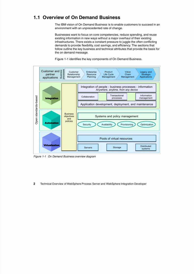
Figure 1-1 identifies the key components of On Demand Business.
Figure 1-1 On Demand Business overview diagram
IntegrationIntegration
AutomationAutomation
VirtualizationVirtualization
Security Availability Provisioning Optimization
Systems and policy management
Integration of people - business processes - information Anywhere, anytime, from any device
Pools of virtual resources
Collaboration Transactionalprocesses Informationmanagement
Application development, deployment, and maintenance
Servers StorageDistributed
systems
Businessobjectives
andpolicies
ProductLife Cycle
Management
Customer RelationshipManagement
EnterpriseResourcePlanning
ValueChain
Management
Legacy andStrategic
Applications
Customer andpartner
applications B u s i n e s s
p r o c e s s e s
O p e n s t a n d a r d s - b a s e d
8/6/2019 WID RedBooks
http://slidepdf.com/reader/full/wid-redbooks 13/128
8/6/2019 WID RedBooks
http://slidepdf.com/reader/full/wid-redbooks 14/128
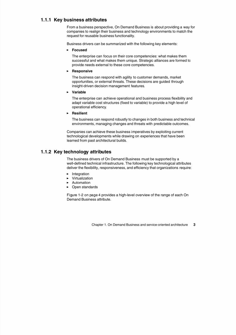
4 Technical Overview of WebSphere Process Server and WebSphere Integration Developer
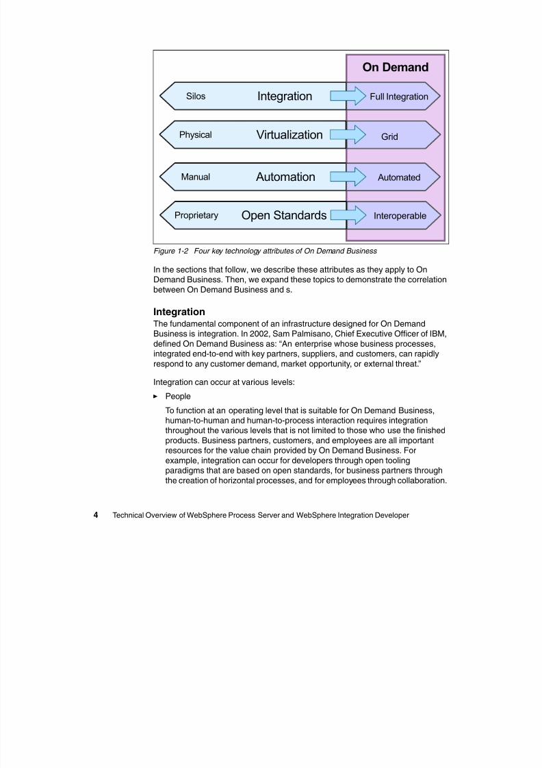
Figure 1-2 Four key technology attributes of On Demand Business
In the sections that follow, we describe these attributes as they apply to OnDemand Business. Then, we expand these topics to demonstrate the correlation
between On Demand Business and s.
IntegrationThe fundamental component of an infrastructure designed for On DemandBusiness is integration. In 2002, Sam Palmisano, Chief Executive Officer of IBM,
defined On Demand Business as: “An enterprise whose business processes,integrated end-to-end with key partners, suppliers, and customers, can rapidly
respond to any customer demand, market opportunity, or external threat.”
Integration can occur at various levels:
People
To function at an operating level that is suitable for On Demand Business,human-to-human and human-to-process interaction requires integrationthroughout the various levels that is not limited to those who use the finished
products. Business partners, customers, and employees are all important
resources for the value chain provided by On Demand Business. Forexample, integration can occur for developers through open toolingparadigms that are based on open standards, for business partners through
the creation of horizontal processes, and for employees through collaboration.
On Demand
Proprietary InteroperableOpen Standards
VirtualizationPhysical
AutomationManual
IntegrationSilos
Grid
Automated
Full Integration
8/6/2019 WID RedBooks
http://slidepdf.com/reader/full/wid-redbooks 15/128
Chapter 1. On Demand Business and service-oriented architecture 5
Process
Recurring elements (security, service level, monitoring, and so on) can beshared by applications to provide horizontal services for decoupling these
reusable application components. The use of SOA and Web services to
implement these processes, including the emerging Business ProcessExecution Language for Web Services (BPEL4WS), is likely to facilitate morerapid changes in these processes so that the business can respond with
agility to changing market conditions.
Applications
Organizations have invested enormous resources and capital into custom
designed and off-the shelf applications. The application integration goal is toleverage, rather than replace, these assets by providing ways of connecting,
routing, and transforming the data that is stored or shared among them.Applications sit on disparate systems in an enterprise or are installedthroughout many enterprises.
Systems
Systems manage, process, and deliver data to the people and applications in
the solution environment. An On Demand Business Operating Environmentrequires the system to be invisible to the elements that interact with it.
Data
Data is the primary business element of a system. The data is the source ofthe information and can more easily be shared through the adoption ofstandards specifications.
VirtualizationVarious areas of technology in our lives exploit virtualization concepts, includingcell phones, personal digital assistants, wireless connectivity, printers, and soforth. Aspects of virtualization draw on widely adopted architectural concepts,
including object oriented design and development, Web services, and XML.
There is a spectrum of virtualization that begins with independent stand-alone
systems on one side (a large mainframe system, perhaps) and grid computing onthe other. In the middle are varying degrees of client-server implementations.
A grid paradigm, an absolute example of on demand virtualization, is a collectionof distributed computing resources that are available over a local or wide area
network and that appear to a user or application as one large virtual computingsystem.
The Internet, the most widely recognized example of vir tualization, provides a
virtual network that supplies access to content and applications.
8/6/2019 WID RedBooks
http://slidepdf.com/reader/full/wid-redbooks 16/128
6 Technical Overview of WebSphere Process Server and WebSphere Integration Developer
The vision is to create virtual dynamic organizations with secure, coordinatedresource-sharing between individuals, institutions, and resources. Grid
computing is an approach to distributed computing that spans locations,organizations, machine architectures, and software boundaries.
Figure 1-1 on page 2 depicts virtualization as a set of virtualized resource poolsbased on:
Servers
This might include partitioning, hypervisors, VM OS, emulators, I/Ovirtualization, virtual Ethernet, and so forth.
Storage
Here, the focus is on the addition of intell igence and value in the network.
Distributed systems
This includes Web services, scheduling, provisioning, workload management,billing and metering, and transaction management.
The goal of grid computing, and thus on demand virtualization, is to provide
unlimited power, collaboration, and information access to everyone connected toa grid.
AutomationAutonomic computing addresses the need of an organization to limit the amount
of time and cost that occurs as a result of:
Overprovisioning New applications and highly skilled labor Disparate technology platforms even within one organization Focus on maintenance, not problem resolution Complexities in operating heterogeneous systems
So how can organizations begin to address these common concerns by using OnDemand Business? This is where autonomic computing comes in. Autonomic
computing can be summarized by four key components:
Self-healingFor a system to keep functioning, it must detect, prevent, and recover from
disruptions with minimal or no human intervention. This requirement isdirectly proportional to increased business dependence on technical
Note: Open Grid Services Architecture (OGSA) is an important starting pointfor grid enablement. For more information about OGSA, refer to the article at:
http://www-106.ibm.com/developerworks/grid/library/gr-visual/
8/6/2019 WID RedBooks
http://slidepdf.com/reader/full/wid-redbooks 17/128
Chapter 1. On Demand Business and service-oriented architecture 7
infrastructures. The need for self-healing is directly proportional to theorganization’s availability requirement.
Self-configuring
The system can adapt dynamically to changing environments, add and
remove components to and from the systems, and change the environment toadapt to variable workloads.
Self-optimization
Configuration that maximizes operational efficiency, including resource tuning
and workload management, alleviates the constant drain on resources toperform routine tasks. The goal is to tune systems to respond to the workloadchanges. Systems must monitor and self-tune continuously, adapting and
learning from the environment around them.
Self-protecting
Security is one of the inhibitors of the adoption of SOAs as organizations
prepare themselves to share data externally. Self-protection requires thesystem to provide safe alternatives for securing information and data.
Self-protecting automation works by anticipating, detecting, identifying, andprotecting systems from external or internal threats.
Open standards
Open standards affect the On Demand Business Operating Environment acrossthe previously defined levels, including automation, integration, and virtualization.Each of these elements leverage open standards specifications to achieve their
objectives. Open standards are the key element of flexibility and interoperabilitythroughout heterogeneous systems.
The global adoption of a standard specification enables the disparate systems to
interact with each other. The underlying platforms might be completely differentand independent, but open standards enable processes to be built despite (or
because of) these differences.
Open standards provide the On Demand Business Operating Environment with astandard, open mechanism to invoke system services.
1.1.3 Key requirements for integration flexibility
For the business integration that is required by On Demand Business whilemaintaining the maximum flexibility of implementation, the requirements shown
in Figure 1-3 on page 8 must be met.
8/6/2019 WID RedBooks
http://slidepdf.com/reader/full/wid-redbooks 18/128
8 Technical Overview of WebSphere Process Server and WebSphere Integration Developer
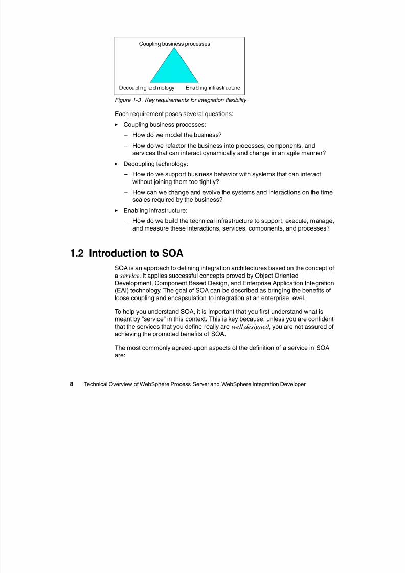
Figure 1-3 Key requirements for integration flexibility
Each requirement poses several questions:
Coupling business processes:
– How do we model the business?– How do we refactor the business into processes, components, and
services that can interact dynamically and change in an agile manner?
Decoupling technology:
– How do we support business behavior with systems that can interact
without joining them too tightly?
– How can we change and evolve the systems and interactions on the time
scales required by the business? Enabling infrastructure:
– How do we build the technical infrastructure to support, execute, manage,and measure these interactions, services, components, and processes?
1.2 Introduction to SOA
SOA is an approach to defining integration architectures based on the concept ofa service. It applies successful concepts proved by Object OrientedDevelopment, Component Based Design, and Enterprise Application Integration(EAI) technology. The goal of SOA can be described as bringing the benefits of
loose coupling and encapsulation to integration at an enterprise level.
To help you understand SOA, it is important that you first understand what ismeant by “service” in this context. This is key because, unless you are confidentthat the services that you define really are well designed , you are not assured of
achieving the promoted benefits of SOA.
The most commonly agreed-upon aspects of the definition of a service in SOA
are:
Coupling business processes
Decoupling technology Enabling infrastructure
8/6/2019 WID RedBooks
http://slidepdf.com/reader/full/wid-redbooks 19/128
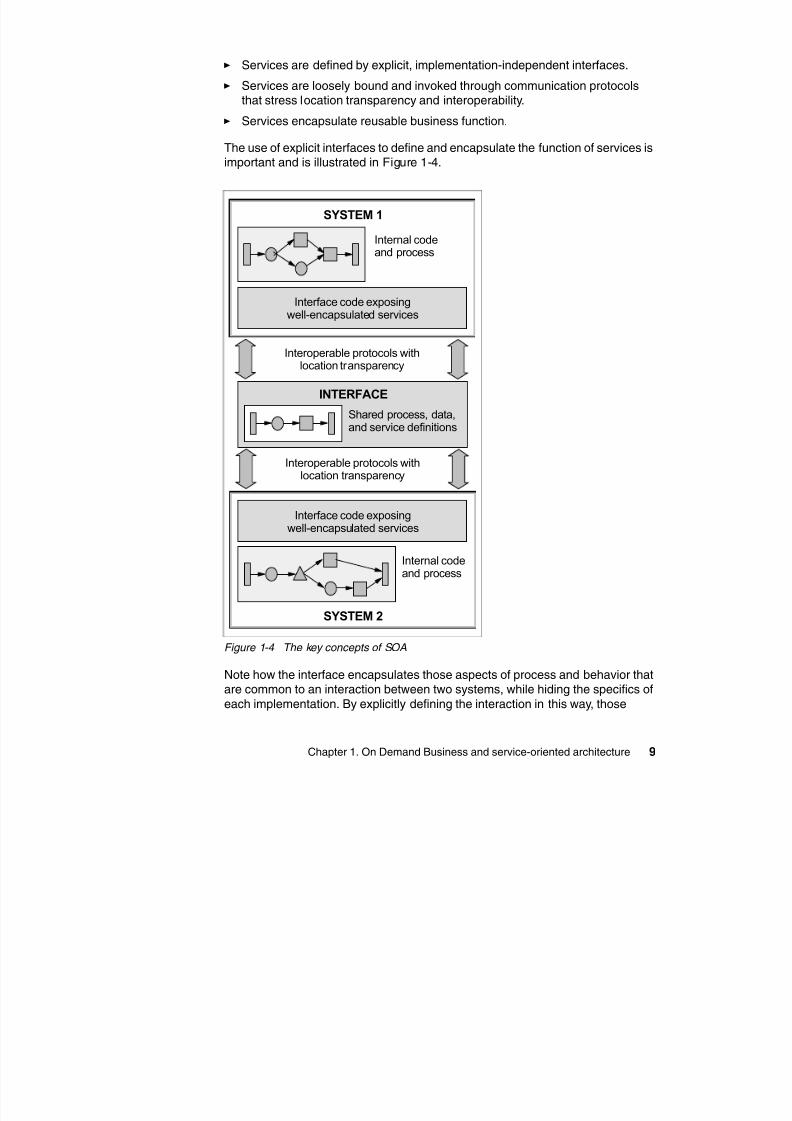
8/6/2019 WID RedBooks
http://slidepdf.com/reader/full/wid-redbooks 20/128
10 Technical Overview of WebSphere Process Server and WebSphere Integration Developer
aspects of either system (for example, the platform that they are based on) thatare not part of the interaction can change without affecting the other system.
After the function has been encapsulated and defined as a service in an SOA, itcan be used and reused by one or more systems that participate in the
architecture. For example, when the reuse of a Java™ logging applicationprogramming interface (API) is described as “design time” (when a decision ismade to reuse an available package and bind it into application code), the
intention of SOA is to achieve the reuse of services at:
Runtime: Each service is deployed in one place and one place only and isremotely invoked by anything that must use it. The advantage of this
approach is that changes to the service (for example, to the calculationalgorithm or the reference data that it depends on) need only be applied in a
single place.
Deployment time: Each service is built once but redeployed locally to eachsystem or set of systems that must use it. The advantage of this approach is
the increased flexibility that is needed to achieve performance targets or tocustomize the service (perhaps according to geography).
Note that, in contrast to reusing service implementations at runtime, the
encapsulation of functions as services and their definition with interfaces alsoallows the substitution of one service implementation for another. For example,
the same service might be provided by multiple providers (such as a carinsurance quote service, which might be provided by multiple insurancecompanies), and individual service requesters might be routed to individual
service providers through some intermediary agent.
The encapsulation of services by interfaces and their invocation throughlocation-transparent, interoperable protocols are the basic means by which SOA
increases flexibility and reusability.
1.2.1 Service granularity and choreography
Many descriptions of SOA also refer to “large-grained” services. However,powerful counterexamples of successful, reusable, fine-grained services exist.
For example, getBalance is a useful service that is not large grained. Morerealistically, there are many useful levels of service granularity in most SOAs:
Technical functions (such as logging) Business functions (such as getBalance) Business transactions (such as openAccount) Business processes (such as applyForMortgage)
Some degree of choreography or aggregation is required between eachgranularity level. It is unlikely that all organizations share identical definitions of
8/6/2019 WID RedBooks
http://slidepdf.com/reader/full/wid-redbooks 21/128
Chapter 1. On Demand Business and service-oriented architecture 11
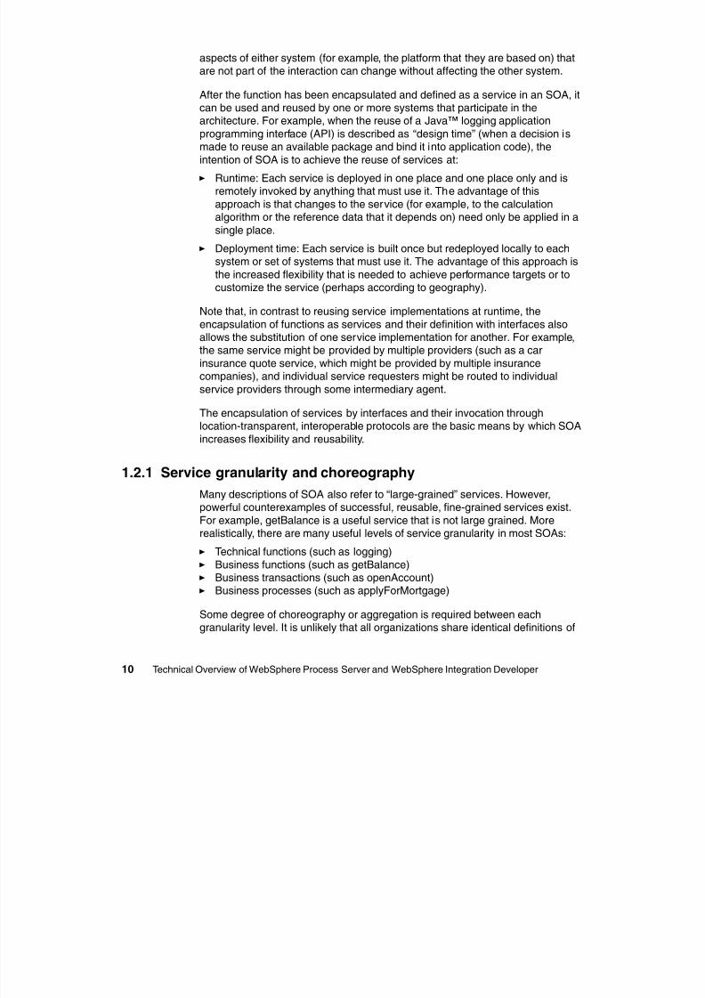
granularity, but each undoubtedly finds it beneficial to define their own. At eachlevel of granularity, it is important that service definitions encapsulate function
well enough that it is reusable. Figure 1-5 shows an example of servicegranularities and the choreographies between them.
Figure 1-5 Service granularity and choreography
The interactions between services of various granularities (Figure 1-5) are:
1. A user submits a request to a self-service application to create a mortgageaccount. The self-service application submits the business process servicerequest (createMortgageAccount) through the service infrastructure to a
Submit
Self-serviceapplication
1
Public createCustomerRecord {
Check and validate parameters...
Request a unique ID
Check postcode against address
Store and commit data
}
4
Service Infrastructure
Authorization andauthentication
servicesLog
Customer management
system
Externalservice
1
9
Service choreographer 3
Submit
Authenticate andauthorize
createMortgageAccount
createCustomerRecord
createCustomerRecord
Implementation
Check PostcodeLog
a cb
Steps a and bomitted for clarity
Steps a and bomitted for clarity
2
8/6/2019 WID RedBooks
http://slidepdf.com/reader/full/wid-redbooks 22/128
12 Technical Overview of WebSphere Process Server and WebSphere Integration Developer
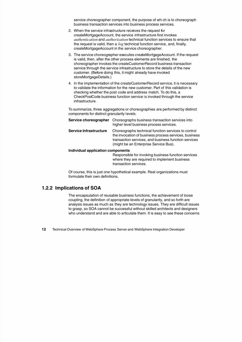
service choreographer component, the purpose of which is to choreographbusiness transaction services into business process services.
2. When the service infrastructure receives the request for
createMortgageAccount, the service infrastructure first invokesauthentication and authorization technical function services to ensure that
the request is valid, then a log technical function service, and, finally,createMortgageAccount in the service choreographer.
3. The service choreographer executes createMortgageAccount. If the requestis valid, then, after the other process elements are finished, the
choreographer invokes the createCustomerRecord business transactionservice through the service infrastructure to store the details of the newcustomer. (Before doing this, it might already have invoked
storeMortgageDetails.)
4. In the implementation of the createCustomerRecord service, it is necessaryto validate the information for the new customer. Part of this validation is
checking whether the post code and address match. To do this, aCheckPostCode business function service is invoked through the service
infrastructure.
To summarize, three aggregations or choreographies are performed by distinctcomponents for distinct granularity levels:
Service choreographer Choreographs business transaction services intohigher level business process services.
Service Infrastructure Choreographs technical function services to controlthe invocation of business process services, business
transaction services, and business function services(might be an Enterprise Service Bus).
Individual application componentsResponsible for invoking business function services
where they are required to implement businesstransaction services.
Of course, this is just one hypothetical example. Real organizations must
formulate their own definitions.
1.2.2 Implications of SOA
The encapsulation of reusable business functions, the achievement of loose
coupling, the definition of appropriate levels of granularity, and so forth areanalysis issues as much as they are technology issues. They are difficult issuesto grasp, so SOA cannot be successful without skilled architects and designers
who understand and are able to articulate them. It is easy to see these concerns
8/6/2019 WID RedBooks
http://slidepdf.com/reader/full/wid-redbooks 23/128
8/6/2019 WID RedBooks
http://slidepdf.com/reader/full/wid-redbooks 24/128
14 Technical Overview of WebSphere Process Server and WebSphere Integration Developer
• Transport protocols (including HTTP, HTTPS, JMS).
• Security at the transport level (HTTPS), at a protocol level(WS-Security), or at both levels
– Web Service Description Language (WSDL) allows Web services to be
self-describing for a loosely coupled architecture.– Standards bodies, including WS-I, W3C, and OASIS, use technologists
from industry leading software vendors (IBM, BEA, Oracle, andMicrosoft®, for example) to accelerate and guide open standards creation
and adoption.
Integration
– Interfaces are provided to wrap service endpoints for a
system-independent architecture and to promote cross-industry
communication.
– SOAs can provide dynamic service discovery and binding, which means
that on demand service integration can occur.
Virtualization
– A key principle of SOA is that services should be invoked by servicerequesters that are oblivious to service implementation details, includinglocation, platform, and, if appropriate to the business scenario, even the
identity of the service provider.
– Grid services and the very framework it all rests on is very much likeobject-oriented programming.
Automation
– Grid technologies are applying SOA principles to implementing
infrastructure services that provide an evolutionary approach to increasedautomation.
For more information about the topics that are covered in this section, visit: IBM Web services
http://www.ibm.com/webservices
IBM on demand Operating Environment
http://www-3.ibm.com/software/info/openenvironment/
IBM developerWorks®: SOA and Web services zone
http://www.ibm.com/developerworks/webservices
8/6/2019 WID RedBooks
http://slidepdf.com/reader/full/wid-redbooks 25/128
Chapter 1. On Demand Business and service-oriented architecture 15
1.4 The On Demand Business Operating Environment
To create truly successful On Demand Business, one must embrace the SOA,
which helps businesses wrap functions (services) to provide loosely coupledaccessibility to functions, flows, and applications.
So how does the Enterprise Service Bus address the IBM vision of On Demand
Business? This section describes the way that the Enterprise Service Bus canhelp businesses create processes that meet the objectives of the capabilities of
an On Demand Business environment.
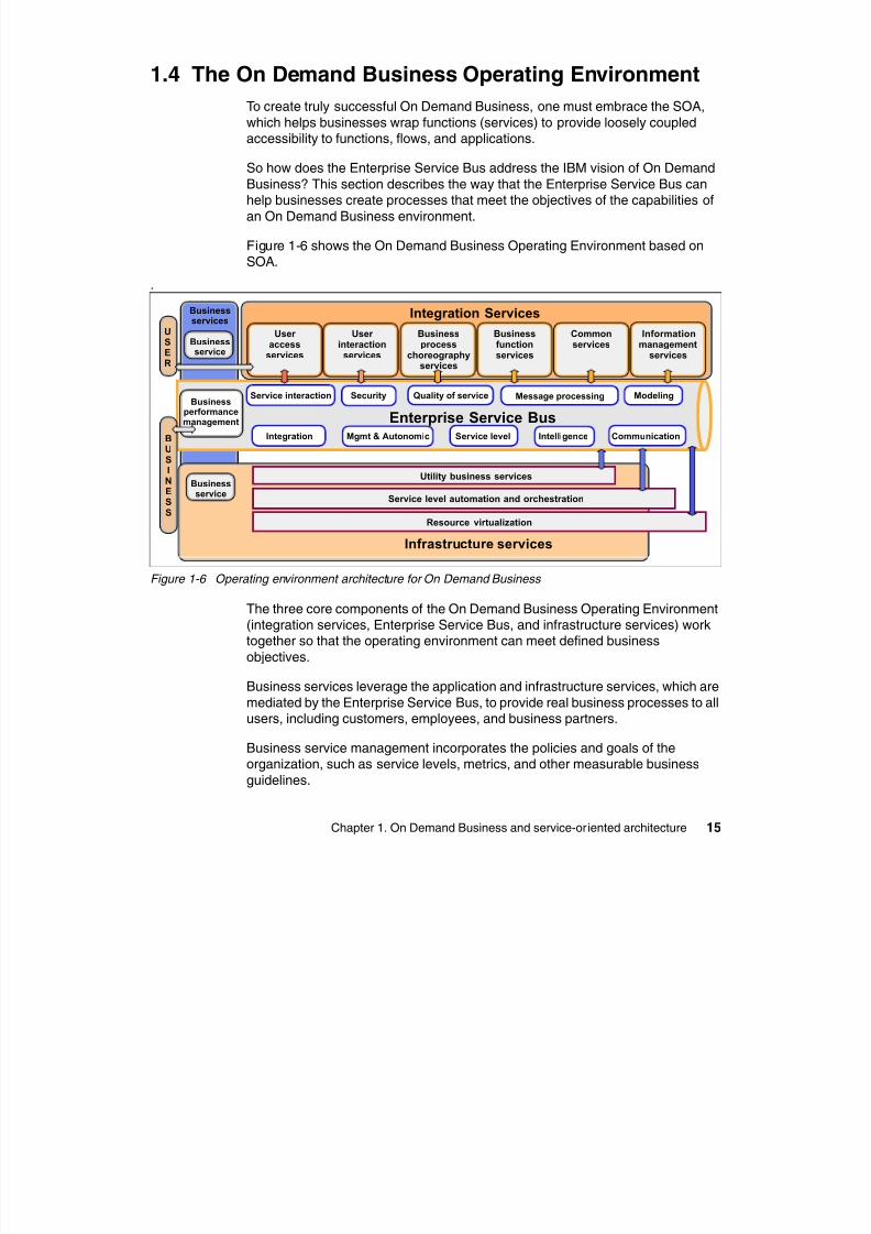
Figure 1-6 shows the On Demand Business Operating Environment based onSOA.
.
Figure 1-6 Operating environment architecture for On Demand Business
The three core components of the On Demand Business Operating Environment(integration services, Enterprise Service Bus, and infrastructure services) worktogether so that the operating environment can meet defined business
objectives.
Business services leverage the application and infrastructure services, which are
mediated by the Enterprise Service Bus, to provide real business processes to allusers, including customers, employees, and business partners.
Business service management incorporates the policies and goals of theorganization, such as service levels, metrics, and other measurable business
guidelines.
Integration Services
Service level automation and orchestration
Informationmanagement
services
Commonservices
Businessfunctionservices
Businessprocess
choreographyservices
User access
services
Security Message processing Modeling
Integration Mgmt & Autonomic Service level Intelligence Communication
Enterprise Service Bus
Utility business services
Resource virtualization
Infrastructure services
Businessperformancemanagement
Businessservice
Businessservice
USER
BUSINESS
Businessservices
Quality of serviceService interaction
User interaction
services
8/6/2019 WID RedBooks
http://slidepdf.com/reader/full/wid-redbooks 26/128
16 Technical Overview of WebSphere Process Server and WebSphere Integration Developer
Infrastructure servicesThe services in the infrastructure category provide and manage the infrastructure
into which business services and their constituents are deployed. These include:
Utility business services
These services support functions such as billing, metering, rating, peering,and settlement and are commonly used, for example, when hosting OnDemand Business services or their components.
Service level automation and orchestration
Service level automation and orchestration provide services that facilitatetranslation of service policy declarations that are associated with businessservices into reality. This is achieved by services that implement autonomic
managers, which monitor the execution of services (more precisely, services
that are instrumented to be managed elements) in the On Demand BusinessOperating Environment according to the policy declarations that they receive.They then analyze their behavior, and if the analysis indicates problems, plan
a meaningful reaction to that problem and initiate execution of that plan. Thisclosed feedback loop is called an M-A-P-E (Monitor, Analyze, Plan, Execute)loop.
Several specializations of such services focus, for example, on managing the
availability, the configuration, or the workload for the managed elements;provisioning resources; performing problem management; handlingend-to-end security for services for the On Demand Business Operating
Environment; or managing data placement.
Resource virtualization services
These services provide the instrumentation of server, storage, network, andother resources. Included is structured (relational) and unstructured
information content that is held in a variety of data sources to allow
management and virtualization of those resources that are under the controlof operating environment resource managers for On Demand Business.
Virtualization services include mapping requirements of business servicesand their components to available resources based on quality of servicedeclarations of the service and knowledge about the current utilization of
available resources.
Besides the fact that they implement very different capabilities that support avariety of patterns for the On Demand Business Operating Environment, the
main difference between the two categories of services is which user roles buildthem and which use them. Infrastructure elements are built by middleware
providers and Independent Software Vendors (ISVs), while integration elementsare constructed by infrastructure and application builders.
8/6/2019 WID RedBooks
http://slidepdf.com/reader/full/wid-redbooks 27/128
Chapter 1. On Demand Business and service-oriented architecture 17
One of the most important insights regarding the On Demand BusinessOperating Environment is that a common pattern supports both application
services and infrastructure services. For example:
Adapters enable integration of existing infrastructure components into theEnterprise Service Bus.
Service choreography is often used for scripting of M-A-P-E execution plans.
The Enterprise Service Bus provides the infrastructure for exchange of eventsbetween managed elements and autonomic managers.
Users interact with infrastructure services using portal user interaction services.
Enterprise Service BusThe Enterprise Service Bus is emerging as a service-oriented infrastructurecomponent that makes large-scale implementation of the SOA principles
manageable in a heterogeneous world.
Applications for On Demand Business are business services built from servicesthat provide a set of capabilities that are worth advertising for use by other
services. Typically, a business service relies on many other services in itsimplementation. Services interact through the Enterprise Service Bus, whichfacilitates mediated interactions between service endpoints. The Enterprise
Service Bus supports event-based interactions as well as message exchange forservice request handling. One innovation of the Enterprise Service Bus is a
common model for messages and events. All messages can become events ifdeploying the service binds the message to a topic in the event space.
For both events and messages, mediations can be used to facilitate interactions(for example, to find services that provide capabilities that a requestor is asking
for or to take care of interface mismatches between requesters and providers that
are compatible in terms of their capabilities). In this context, we use the term service in a very general sense.
It is worth noting that, although from the perspective of the bus all applicationcomponents can be specified through WS-* standards (because the bus requires
a normalized representation for efficient mediated, capability-based matchmaking), this does not imply that they all communicate with SOAP or WS-*
protocol standards. The Enterprise Service Bus supports a broad spectrum ofways to get on and off the bus, including on ramps for existing applications or
business connections that allow external partners in business-to-business (B2B)interaction scenarios to participate in the service interaction game.
8/6/2019 WID RedBooks
http://slidepdf.com/reader/full/wid-redbooks 28/128
18 Technical Overview of WebSphere Process Server and WebSphere Integration Developer
Although they all look the same from the perspective of the Enterprise ServiceBus, services implement different facets of an overall application for On Demand
Business, including:
Realize interactions with people involved in the underlying business process.
Provide adapters to existing applications that have to be integrated. Choreograph the interaction of several services to achieve a business goal.
Watch for potential problems in the execution of the process, ready to takeaction to fix them if they occur.
Manage resources that are needed to perform required business functions.
Therefore, in addition to providing the basic infrastructure for service interactions,
the On Demand Business Operating Environment identifies a set of common
patterns for construction of applications and supports the realization of distinctservice categories that play particular roles in those patterns. The two distinctservice categories are integration and infrastructure service.
The capabilities that are provided by the Enterprise Service Bus facilitate the
interactions between the levels in the On Demand Business OperatingEnvironment.
Integration services
The programming model for On Demand Business services is based onapplication development that uses component (service) assembly. The servicesin the integration category are used by the builders of applications for On
Demand Business to create new business services; they include services thatfacilitate integration and services that provide functions to be integrated:
User access services
Handle adaptation from three orthogonal perspectives:
– Endpoint form factor such as display size, memory, and processor
limitations (ranging from desktop down to pervasive devices)
– Modes of interaction, including conventional display-keyboard interactions,as well as speech-based interactions and combinations (multi-modality)
– Connection types such as peer-to-peer or client/server across a range of
reliabilty connections, including fully disconnected operations
User interaction services
Handle direct interactions with people involved in the business process; for
example, processing work items that are spawned by choreography orcollaborative process elements
8/6/2019 WID RedBooks
http://slidepdf.com/reader/full/wid-redbooks 29/128
Chapter 1. On Demand Business and service-oriented architecture 19
Business process choreography services
Support the execution of other services that express their behavior usingprocess flow or rule technology. Process flows, for example, are used to
describe the interaction of other services (nearly any of the integration kinds,including other process flow services) to perform the tasks required to realize
the functions offered by the new (combined or aggregated) business service
Business function services
Provide the atomic business functions (those that are not composed from
other services) that are required by the overall business service; this includesadapters to packaged or existing custom applications and brand new
application components that are created to realize a functional need that isnot already covered by existing applications
Common servicesImplement useful features, or helper functions, that are designed to be usedby many business services; for example, services that implement
personalization of user access and user interaction services, or for reportingstatus and progress of business services
Information management services
Help to integrate information hosted in a variety of data sources, such as
databases or existing applications; to access (query, update, and search) that
information; to analyze information from those sources in businessintelligence scenarios; or to take care of metadata about information andservices that are used and provided by the business services that are part ofthe On Demand Business Operating Environment.
Integration services are hosted by application services that provide containerfacilities for simplifying their participation in interactions with other integration
services and with the infrastructure services for the On Demand BusinessOperating Environment. Integration service developers focus on realizing the
business logic that they care about, assembling integration services that providerequired business function and declaring expected quality of service.
Programmers and administrators annotate their applications and services with
policy declarations that specify quality of service. The application container (andthe Enterprise Service Bus) automates the interactions with infrastructureservices to achieve the expressed policies. An application container also
provides generic facilities such as taking care of security or transactionmanagement requirements for the services that it hosts, and kind-specific
facilities such as generating the events reporting status and the progress ofbusiness process choreography services.
8/6/2019 WID RedBooks
http://slidepdf.com/reader/full/wid-redbooks 30/128
20 Technical Overview of WebSphere Process Server and WebSphere Integration Developer
1.5 Life cycle of an On Demand Business applicationand the role of WebSphere Process Integration
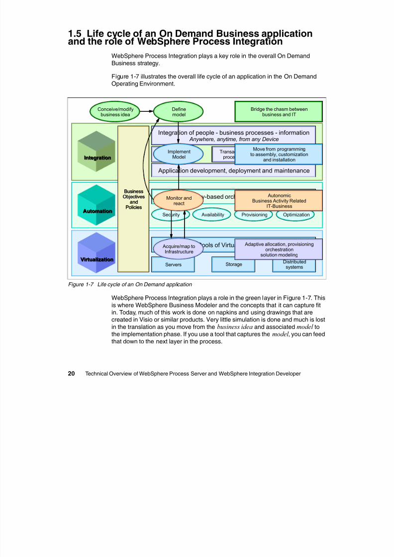
WebSphere Process Integration plays a key role in the overall On Demand
Business strategy.
Figure 1-7 illustrates the overall life cycle of an application in the On DemandOperating Environment.
Figure 1-7 Life cycle of an On Demand application
WebSphere Process Integration plays a role in the green layer in Figure 1-7. This
is where WebSphere Business Modeler and the concepts that it can capture fitin. Today, much of this work is done on napkins and using drawings that arecreated in Visio or similar products. Very little simulation is done and much is lost
in the translation as you move from the business idea and associated model tothe implementation phase. If you use a tool that captures the model , you can feed
that down to the next layer in the process.
IntegrationIntegration
AutomationAutomation
VirtualizationVirtualization
Security Availability Provisioning Optimization
Policy-based orchestration
Integration of people - business processes - information Anywhere, anytime, from any Device
Pools of Virtual Resources
CollaborationTransactional
processesInformation
Management
Application development, deployment and maintenance
Servers Storage Distributedsystems
BusinessObjectives
andPolicies
ImplementModel
Move from programmingto assembly, customization
and installation
AutonomicBusiness Activity Related
IT-Business
Adaptive allocation, provisioningorchestration
solution modeling
Bridge the chasm betweenbusiness and IT
Conceive/modifybusiness idea
Definemodel
Acquire/map toInfrastructure
Monitor andreact
BusinessObjectives
andPolicies
8/6/2019 WID RedBooks
http://slidepdf.com/reader/full/wid-redbooks 31/128
Chapter 1. On Demand Business and service-oriented architecture 21
The blue implementation layer is where you accept the results of the modelingactivity and transform them into an implementation that will run in your runtime.
Abstract processes, for example, that are sketched out in WebSphere BusinessModeler are finished in this layer.
A key goal of WebSphere Process Integration is to transform the activities in thislater from writing code to scripting and assembly. This is achieved by building upthe appropriate services and components that are concrete representations of
the model. After these are available and they have interfaces at the correct levelof granularity, the scripting and assembly can be done. Scripting is a synonym for
flows and this is where BPEL-based choreography technology fits in. In this layer,you can build flows that represent a business process and have the runtime toexecute them.
Assembly and customization is another aspect that is important. Here you wiretogether components. This is a not a flow concept, but more of an assembly idea,where high level components support specific interfaces and depend on other
interfaces for implementation.
As we move to the red layer, WebSphere Business Monitor provides thebusiness-level monitoring. You can build dashboards to see how the business is
performing and register actions to take place based on business level events thatare occurring in the system. WebSphere Business Monitor will work inconjunction with the other tools that provide monitoring of the infrastructure
events. Because the IT and business events are both based on a Common EventInfrastructure, there is correlation between business and IT events, thus
providing faster problem resolution because you can determine exactly whathappened where and when, and fix things at a business and infrastructure level.
The final pink layer speaks to the core runtime that provides workload
management across disparate resources and efficient utilization of all availableIT resources. Solution Modeling and part of the WebSphere Business Modeler
solution is a starting point for configurations and service level agreements (SLAs)
and thus has some affinity at this layer.
WebSphere Process Integration is based on the WebSphere Application Server,
which provides a number of the key technologies that otherwise would have to bere-implemented by WebSphere Process Integration. Examples are infrastructure
services around transaction management and workload management.
WebSphere Process Integration also builds ideas upon the basic virtualizaton ofresources that are being enabled and extended in the base application server.
As the application server continues to enable On Demand Business, the processserver benefits from these features as well.
8/6/2019 WID RedBooks
http://slidepdf.com/reader/full/wid-redbooks 32/128
22 Technical Overview of WebSphere Process Server and WebSphere Integration Developer
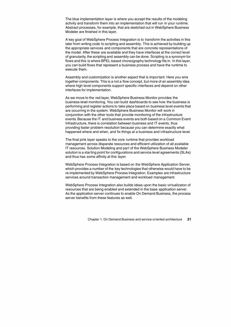
The remainder of this paper focuses on the key concepts and components ofWebSphere Process Server and WebSphere Integration Developer, two products
that constitute WebSphere Process Integration. WebSphere Process Serverallows the development and execution of standards-based business integration
applications in an SOA. Based on the robust J2EE 1.4 infrastructure and
associated platform services provided by WebSphere Application Server,WebSphere Process Server can help you meet current business integration
challenges. This includes, but is not limited to, business process automation.
WebSphere Integration Developer delivers role-based development for
integration projects based on the Eclipse 3.0 platform. WebSphere IntegrationDeveloper complements WebSphere Business Modeler and can be used inconjunction with other Rational® tools to create a unique, integrated, and
powerful development platform. Each user has a tooling perspective based on
their particular role (J2EE Developer, Business Analyst, or IntegrationDeveloper). This allows the user to focus on just the editors and tools that theyneed for their role, which leads to unparalleled productivity.
Figure 1-8 shows which products and tools could be used in which phase of asoftware development and deployment project.
Figure 1-8 WebSphere Process Integration and related products
Process execution/choreography
Services
Interactionglue
Process modeling
Monitor Analysis
Optimize
Existingcomponents
Processrequirements
Manageexecution
Participate
Tool:WebSphereIntegrationDeveloper
Tool:WebSphereIntegrationDeveloper
Tool:WebSphereBusinessModeler
Tool:WebSphereBusinessModeler
Tool:WebSphereBusiness
Monitor
Tool:WebSphereBusiness
Monitor
WebSphereProcessServer
WebSphereProcessServer
Web andportalclients
Web andportalclients
Tool:Rational
ApplicationDeveloper
Tool:Rational
ApplicationDeveloper
8/6/2019 WID RedBooks
http://slidepdf.com/reader/full/wid-redbooks 33/128
© Copyright IBM Corp. 2005. All rights reserved. 23
Chapter 2. Building blocks ofWebSphere Process Server
This chapter discusses the programming model and main building blocks ofWebSphere Process Server, grouped around three concepts:
Invocation Data Composition
2
S
8/6/2019 WID RedBooks
http://slidepdf.com/reader/full/wid-redbooks 34/128
24 Technical Overview of WebSphere Process Server and WebSphere Integration Developer
2.1 WebSphere Process Integration programmingmodel
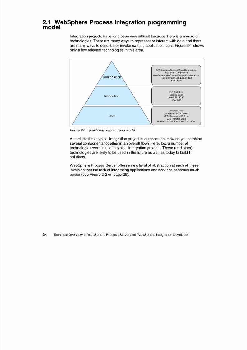
Integration projects have long been very difficult because there is a myriad of
technologies. There are many ways to represent or interact with data and there
are many ways to describe or invoke existing application logic. Figure 2-1 showsonly a few relevant technologies in this area.
Figure 2-1 Traditional programming model
A third level in a typical integration project is composition. How do you combineseveral components together in an overall flow? Here, too, a number oftechnologies were in use in typical integration projects. These (and other)
technologies are likely to be used in the future as well as today to build ITsolutions.
WebSphere Process Server offers a new level of abstraction at each of theselevels so that the task of integrating applications and services becomes mucheasier (see Figure 2-2 on page 25).
Data
Invocation
Composition
JDBC Row SetJava Bean, JAXB ObjectJMS Message, JCA Data
EJB Transfer BeanJAX-RPC POJO, EMF Data, XML DOM
EJB StatelessSession Bean
JAX-RPC, JDBCJCA, JMS
EJB Stateless Session Bean CompositionJava Bean Composition
WebSphere InterChange Server CollaborationsFlow Definition Language (FDL)
BPEL4WS
8/6/2019 WID RedBooks
http://slidepdf.com/reader/full/wid-redbooks 35/128
Chapter 2. Building blocks of WebSphere Process Server 25
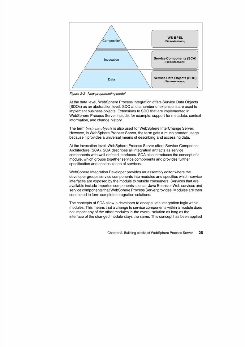
Figure 2-2 New programming model
At the data level, WebSphere Process Integration offers Service Data Objects
(SDOs) as an abstraction level. SDO and a number of extensions are used toimplement business objects. Extensions to SDO that are implemented inWebSphere Process Server include, for example, support for metadata, context
information, and change history.
The term business objects is also used for WebSphere InterChange Server.However, in WebSphere Process Server, the term gets a much broader usagebecause it provides a universal means of describing and accessing data.
At the invocation level, WebSphere Process Server offers Service ComponentArchitecture (SCA). SCA describes all integration artifacts as service
components with well-defined interfaces. SCA also introduces the concept of amodule, which groups together service components and provides further
specification and encapsulation of services.
WebSphere Integration Developer provides an assembly editor where thedeveloper groups service components into modules and specifies which service
interfaces are exposed by the module to outside consumers. Services that areavailable include imported components such as Java Beans or Web services andservice components that WebSphere Process Server provides. Modules are then
connected to form complete integration solutions.
The concepts of SCA allow a developer to encapsulate integration logic within
modules. This means that a change to service components within a module doesnot impact any of the other modules in the overall solution as long as theinterface of the changed module stays the same. This concept has been applied
Composition
Invocation
Data Service Data Objects (SDO)(Plus extensions)
Service Components (SCA)(Plus extensions)
WS-BPEL(Plus extensions)
throughout WebSphere Process Server All integration artifacts in WebSphere
8/6/2019 WID RedBooks
http://slidepdf.com/reader/full/wid-redbooks 36/128
26 Technical Overview of WebSphere Process Server and WebSphere Integration Developer
throughout WebSphere Process Server. All integration artifacts in WebSphereProcess Server (processes, business rules, human tasks, and so on) are
represented as SCA service components. This creates an environment withgreat flexibility. It is possible, for example, to replace a human task for an
approval with a business rule for automatic approval simply by replacing the
service components in the assembly diagram without changing either a businessprocess or the caller of the business process.
With SCA, you can invoke service components using synchronous andasynchronous programming styles. You can assemble modules into overall
solutions where asynchronous channels between service components andmodules can increase the overall throughput and flexibility of the system.
At the composition level, WebSphere Process Server offers business processexecution language for Web services (WS-BPEL), sometimes also referred to as
BPEL4WS.
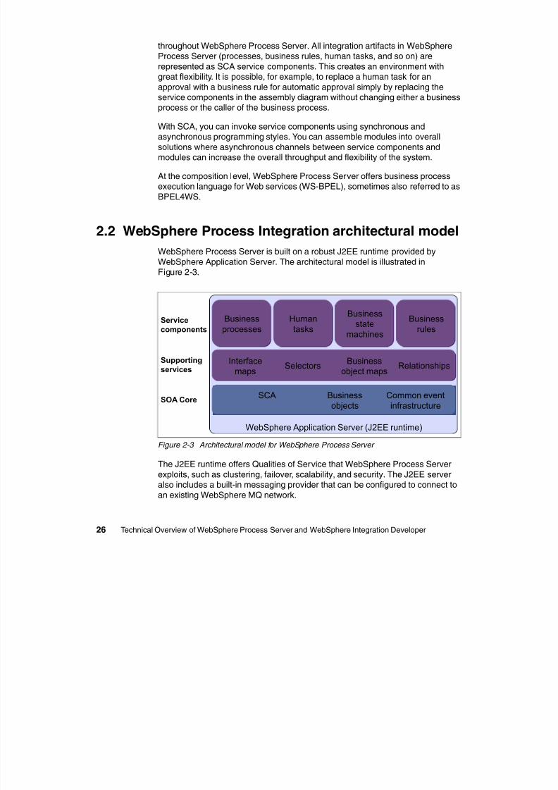
2.2 WebSphere Process Integration architectural model
WebSphere Process Server is built on a robust J2EE runtime provided by
WebSphere Application Server. The architectural model is illustrated inFigure 2-3.
Figure 2-3 Architectural model for WebSphere Process Server
The J2EE runtime offers Qualities of Service that WebSphere Process Serverexploits, such as clustering, failover, scalability, and security. The J2EE serveralso includes a built-in messaging provider that can be configured to connect to
an existing WebSphere MQ network.
SOA CoreSCA Business
objectsCommon eventinfrastructure
Humantasks
Humantasks
Businessstate
machines
Businessstate
machines
Businessrules
Businessrules
Businessprocesses
Businessprocesses
Service
components
WebSphere Application Server (J2EE runtime)
Supporting
servicesInterface
mapsBusiness
object mapsRelationshipsSelectors
Also in the infrastructure layer is the Common Event Infrastructure, which is the
8/6/2019 WID RedBooks
http://slidepdf.com/reader/full/wid-redbooks 37/128
Chapter 2. Building blocks of WebSphere Process Server 27
y ,foundation for monitoring applications. IBM uses this infrastructure throughout
the IBM product portfolio; monitoring products from Tivoli® and WebSphere(WebSphere Business Monitor) exploit it. The event definition (Common
Business Event, or CBE) is being standardized by the OASIS standards body so
that other companies and clients can use the same infrastructure to monitor theirenvironments.
On top of this infrastructure, WebSphere Process Server implements a layercalled the SOA core. To do integration in an SOA properly, you must have a
single invocation model and a single data model. SOA is this invocation model:every integration component is described using an interface. These services canthen be assembled in a component assembly editor; the result is a very flexible,
encapsulated solution. Business objects are the universal data description. They
are being used as data going in and out of services and are based on the SDOstandard.
SCA Bindings describe the physical description of components. Services thatcan be accessed include Plain Old Java Objects (POJOs), EJBs, Web services,JMS messages, and adapters.
On top of this SOA core layer, WebSphere Process Server implements a numberof components and services that can be used in an integration solution:
Business processes: The business process component in WebSphereProcess Server implements a WS-BPEL compliant process engine. Userscan develop and deploy business processes with support for long and shortrunning business processes and a robust compensation model in a highly
scalable infrastructure. WS-BPEL models can be created in WebSphereIntegration Developer or imported from a business model that has been
created in WebSphere Business Modeler.
Human tasks: Human tasks in WebSphere Process Server are stand-alone
components that can be used to assign work to employees or to invoke any
other service. Additionally, the Human Task Manager supports the ad-hoccreation and tracking of tasks. Existing Lightweight Directory Access Protocol(LDAP) directories (and operating system repositories and the WebSphereuser registry) can be used to access staff information. Of course, WebSphere
Process Server supports multi-level escalation for human tasks, includinge-mail notification.
WebSphere Process Server also includes an extensible Web client that can
be used to work with tasks or processes. This Web client is built based on a
set of reusable Java Server Faces (JSF) components that can also be used tocreate custom clients or embed human task functionality into other Webapplications.
Business state machines: A business state machine provides another way of
8/6/2019 WID RedBooks
http://slidepdf.com/reader/full/wid-redbooks 38/128
28 Technical Overview of WebSphere Process Server and WebSphere Integration Developer
p ymodeling a business process. Businesses can represent their business
processes based on states and events that sometimes are easier to modelthan a graph-oriented business process model. One example is an ordering
process where the order can be cancelled or modified at any time during the
order process. Business rules: Business rules are a means of implementing and enforcing
business policy through the externalization of business. This allows dynamicchanges of a business process for a more responsive business environment.Business rule authoring is supported by an Eclipse-based desktop tool.
WebSphere Process Server also includes a Web-based runtime tool forbusiness analysts so that business rules can be updated as business needs
dictate without affecting other SCA services.
These components can use the features of a number of supporting services inWebSphere Process Server. Most of these can be classified as some form of
transformation, which is not surprising. A number of the transformationchallenges in the process of connecting components and external services are
addressed by a component of WebSphere Process Server:
Interface maps: Very often interfaces of existing components matchsemantically but not syntactically (for example, updateCustomer versus.
updateCustomerInDB2). This is especially true for already existingcomponents and services. Interface maps translate these calls so that these
components can be invoked. Additionally, business object maps can be usedto translate the actual business object parameters of a service invocation.
Business object maps: Used to translate one type of business object intoanother type, these maps can be used in a variety of ways (for example, as aninterface map to convert one type of parameter data into another).
Relationships: In business integration scenarios, it is often necessary toaccess the same data, such as customer records, in various back-endsystems (for example, Enterprise Resource Planning and Customer
Relationship Management). A common problem with keeping businessobjects in sync is that different back-end systems use different keys to
represent the same objects. The WebSphere Process Server relationshipservice establishes relationship instances between objects in these disparate
systems. These relationships are typically accessed from a business objectmap while one business object format is being transformed into another.
Selector: Different services that all share the same interface can be selectedand invoked dynamically by a selector. For example, a customer support
process might use different human task implementations during differenttimes of the day. Work is routed to different support centers (Americas,Europe, and Asia-Pacific) based on the time of day. WebSphere Process
Server offers a Web-based interface for dynamic updates to selection criteria
8/6/2019 WID RedBooks
http://slidepdf.com/reader/full/wid-redbooks 39/128
Chapter 2. Building blocks of WebSphere Process Server 29
and target services.
2.3 Invocation: SCA
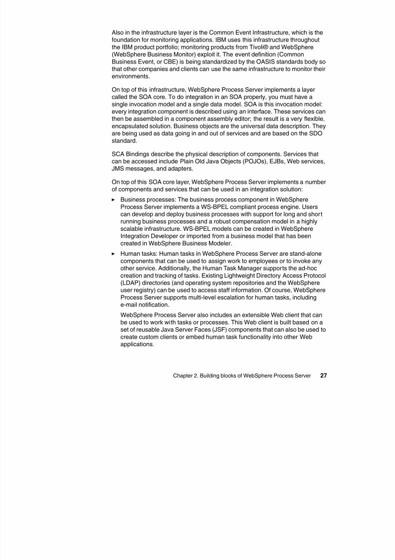
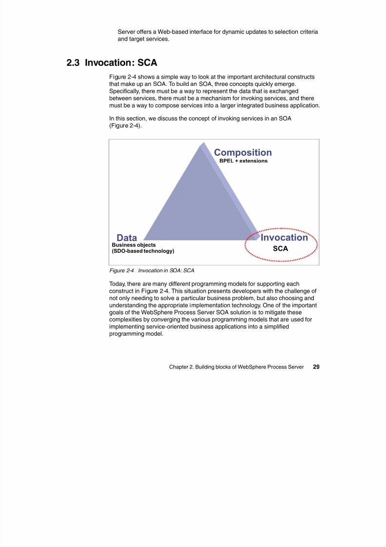
Figure 2-4 shows a simple way to look at the important architectural constructsthat make up an SOA. To build an SOA, three concepts quickly emerge.
Specifically, there must be a way to represent the data that is exchangedbetween services, there must be a mechanism for invoking services, and there
must be a way to compose services into a larger integrated business application.
In this section, we discuss the concept of invoking services in an SOA(Figure 2-4).
Figure 2-4 Invocation in SOA: SCA
Today, there are many different programming models for supporting each
construct in Figure 2-4. This situation presents developers with the challenge ofnot only needing to solve a particular business problem, but also choosing and
understanding the appropriate implementation technology. One of the importantgoals of the WebSphere Process Server SOA solution is to mitigate thesecomplexities by converging the various programming models that are used for
implementing service-oriented business applications into a simplifiedprogramming model.
SCABusiness objects(SDO-based technology)
BPEL + extensions
Data Invocation
Composition
2.3.1 Anatomy of the SCA
8/6/2019 WID RedBooks
http://slidepdf.com/reader/full/wid-redbooks 40/128
30 Technical Overview of WebSphere Process Server and WebSphere Integration Developer
SCA is the service-oriented component model. It provides an abstraction thatcovers stateless session EJBs, Web services, POJOs, BPEL4WS processes,database access, Enterprise Information System (EIS) access, and so on. SCA
separates business logic from infrastructure logic so that applicationprogrammers can focus on the business problem. SCA covers both the usage of
services and the development of services. It provides a uniform model forapplication programmers and for tools.
SCA is a universal model for business services that publish or operate on
business data. SDOs provide the universal model for business data. SDO isdiscussed in 2.4, “Data: Business objects and SDO” on page 37.
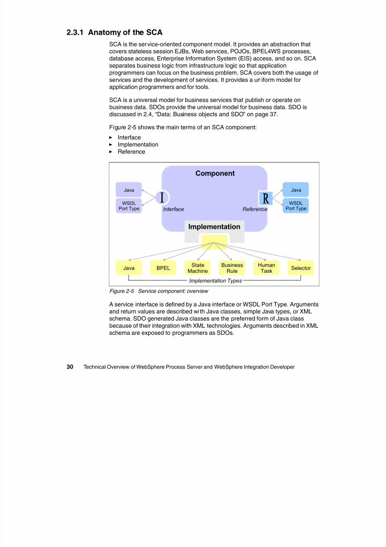
Figure 2-5 shows the main terms of an SCA component:
Interface Implementation Reference
Figure 2-5 Service component: overview
A service interface is defined by a Java interface or WSDL Port Type. Argumentsand return values are described with Java classes, simple Java types, or XMLschema. SDO generated Java classes are the preferred form of Java class
because of their integration with XML technologies. Arguments described in XMLschema are exposed to programmers as SDOs.
HumanTask
Java BPELBusiness
RuleSelector
StateMachine
Implementation Types
Java
WSDLPort Type Interface Reference
Java
WSDLPort Type
Component
Implementation
A component exposes business-level interfaces to its application business logicso that the service can be used or invoked The interface of a component defines
8/6/2019 WID RedBooks
http://slidepdf.com/reader/full/wid-redbooks 41/128
Chapter 2. Building blocks of WebSphere Process Server 31
so that the service can be used or invoked. The interface of a component defines
the operations that can be called and the data that is passed, such as inputarguments, returned values, and exceptions. An import and export also has
interfaces so that the published service can be invoked.
All components have interfaces of the WSDL type. Only Java componentssupport Java-type interfaces. If a component, import or export, has more than
one interface, all interfaces must be the same type.
A component can be called synchronously or asynchronously; this isindependent of whether the implementation is synchronous or asynchronous.The component interfaces are defined in the synchronous form and
asynchronous support is also generated for them. You can specify a preferredinteraction style as synchronous or asynchronous. The asynchronous type
advertises to users of the interface that it contains at least one operation that cantake a significant amount of time to complete. As a consequence, the calling
service must avoid keeping a transaction open while waiting for the operation tocomplete and send its response. The interaction style applies to all theoperations in the interface.
You can also apply a role-based permission qualifier to an interface so that onlyauthorized applications can invoke the service with that interface. If theoperations require different levels of permission for their use, you must define
separate interfaces to control their access.
A service can be implemented in a range of languages (for example Java, BPEL,
state-machine definitions, and so on). When implementing a service, the focus ison the business purpose and less on infrastructure technology.
SCA and non-SCA services can use other service components in their
implementations. They do not hard code the other services they use. Theydeclare soft links called service references. Service wires resolve service
references. You can use SCA wiring to create SCA applications by componentassembly.
Figure 2-6 on page 32 shows a service component and a number of references.When a component wants to use the services of another component, it must
have a partner reference or simply a reference. We can consider an in-linereference, which means that the referenced service component is defined within
the same scope of the referencing component. In other words, both componentsare defined within the same module.
Applications that are not defined as SCA components (for example, JavaServer
Pages, or JSPs) can still invoke SCA components; they do so through the use ofstand-alone references. Stand-alone references contain partner references that
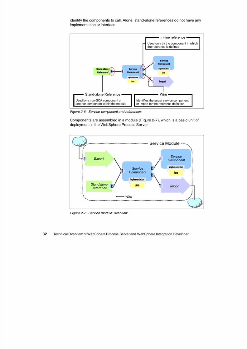
8/6/2019 WID RedBooks
http://slidepdf.com/reader/full/wid-redbooks 42/128
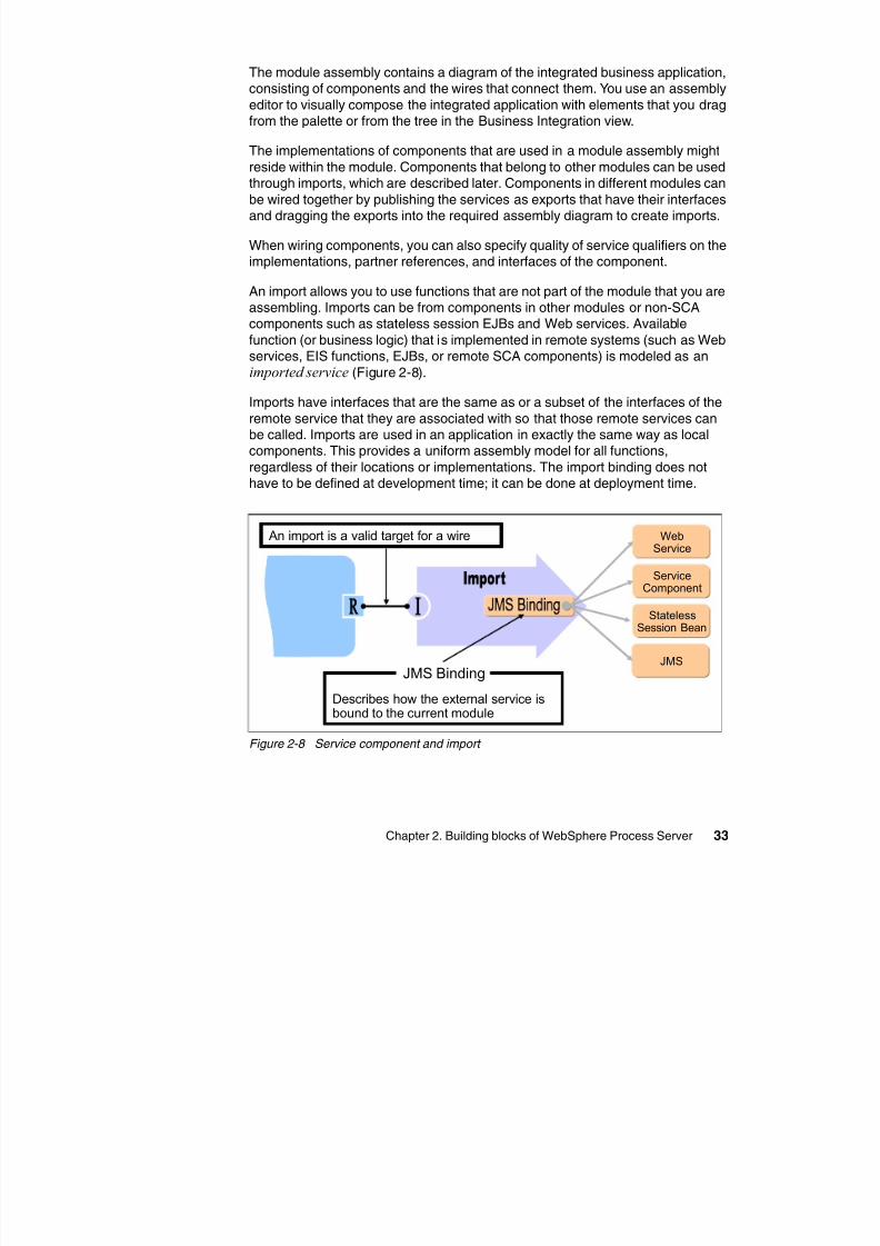
The module assembly contains a diagram of the integrated business application,consisting of components and the wires that connect them You use an assembly
8/6/2019 WID RedBooks
http://slidepdf.com/reader/full/wid-redbooks 43/128
Chapter 2. Building blocks of WebSphere Process Server 33
consisting of components and the wires that connect them. You use an assembly
editor to visually compose the integrated application with elements that you dragfrom the palette or from the tree in the Business Integration view.
The implementations of components that are used in a module assembly might
reside within the module. Components that belong to other modules can be usedthrough imports, which are described later. Components in different modules can
be wired together by publishing the services as exports that have their interfacesand dragging the exports into the required assembly diagram to create imports.
When wiring components, you can also specify quality of service qualifiers on theimplementations, partner references, and interfaces of the component.
An import allows you to use functions that are not part of the module that you are
assembling. Imports can be from components in other modules or non-SCAcomponents such as stateless session EJBs and Web services. Available
function (or business logic) that is implemented in remote systems (such as Webservices, EIS functions, EJBs, or remote SCA components) is modeled as animported service (Figure 2-8).
Imports have interfaces that are the same as or a subset of the interfaces of the
remote service that they are associated with so that those remote services canbe called. Imports are used in an application in exactly the same way as local
components. This provides a uniform assembly model for all functions,regardless of their locations or implementations. The import binding does nothave to be defined at development time; it can be done at deployment time.
Figure 2-8 Service component and import
An import is a valid target for a wire
Describes how the external service isbound to the current module
JMS Binding
WebService
ServiceComponent
StatelessSession Bean
JMS
An export is a published interface from a component (Figure 2-9) that offers thecomponent business service to the outside world, for example, as a Web service.
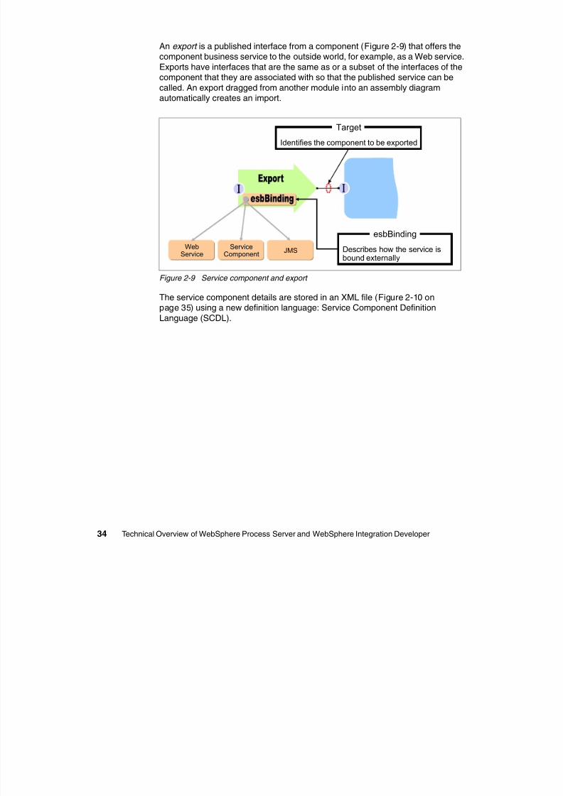
8/6/2019 WID RedBooks
http://slidepdf.com/reader/full/wid-redbooks 44/128
34 Technical Overview of WebSphere Process Server and WebSphere Integration Developer
component business service to the outside world, for example, as a Web service.
Exports have interfaces that are the same as or a subset of the interfaces of thecomponent that they are associated with so that the published service can be
called. An export dragged from another module into an assembly diagram
automatically creates an import.
Figure 2-9 Service component and export
The service component details are stored in an XML file (Figure 2-10 onpage 35) using a new definition language: Service Component Definition
Language (SCDL).
Describes how the service isbound externally
esbBinding
Identifies the component to be exported
Target
WebService
ServiceComponent
JMS
<?xml version="1 0" encoding="UTF 8"?>
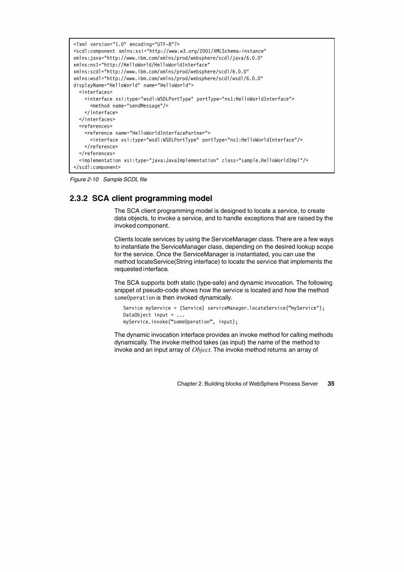
8/6/2019 WID RedBooks
http://slidepdf.com/reader/full/wid-redbooks 45/128
Chapter 2. Building blocks of WebSphere Process Server 35
Figure 2-10 Sample SCDL file
2.3.2 SCA client programming model
The SCA client programming model is designed to locate a service, to createdata objects, to invoke a service, and to handle exceptions that are raised by theinvoked component.
Clients locate services by using the ServiceManager class. There are a few ways
to instantiate the ServiceManager class, depending on the desired lookup scope
for the service. Once the ServiceManager is instantiated, you can use themethod locateService(String interface) to locate the service that implements therequested interface.
The SCA supports both static (type-safe) and dynamic invocation. The following
snippet of pseudo-code shows how the service is located and how the methodsomeOperation is then invoked dynamically.
Service myService = (Service) serviceManager.locateService(“myService");DataObject input = ...myService.invoke(“someOperation”, input);
The dynamic invocation interface provides an invoke method for calling methods
dynamically. The invoke method takes (as input) the name of the method toinvoke and an input array of Object . The invoke method returns an array of
<?xml version="1.0" encoding="UTF-8"?><scdl:component xmlns:xsi="http://www.w3.org/2001/XMLSchema-instance"xmlns:java="http://www.ibm.com/xmlns/prod/websphere/scdl/java/6.0.0"xmlns:ns1="http://HelloWorld/HelloWorldInterface"
xmlns:scdl="http://www.ibm.com/xmlns/prod/websphere/scdl/6.0.0"xmlns:wsdl="http://www.ibm.com/xmlns/prod/websphere/scdl/wsdl/6.0.0"displayName="HelloWorld" name="HelloWorld"><interfaces><interface xsi:type="wsdl:WSDLPortType" portType="ns1:HelloWorldInterface"><method name="sendMessage"/>
</interface></interfaces><references><reference name="HelloWorldInterfacePartner">
<interface xsi:type="wsdl:WSDLPortType" portType="ns1:HelloWorldInterface"/></reference>
</references><implementation xsi:type="java:JavaImplementation" class="sample.HelloWorldImpl"/>
</scdl:component>
Object also. Ideally, the input is an SDO; however, ordinary Java classes can beused, too.
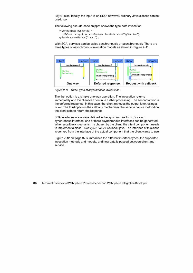
8/6/2019 WID RedBooks
http://slidepdf.com/reader/full/wid-redbooks 46/128
36 Technical Overview of WebSphere Process Server and WebSphere Integration Developer
The following pseudo-code snippet shows the type-safe invocation:
MyServiceImpl myService =
(MyServiceImpl) serviceManager.locateService(“myService");myService.someMethod(“input”);
With SCA, services can be called synchronously or asynchronously. There arethree types of asynchronous invocation models as shown in Figure 2-11.
Figure 2-11 Three types of asynchronous invocations
The first option is a simple one-way operation. The invocation returns
immediately and the client can continue further processing. The second option isthe deferred response. In this case, the client retrieves the output later, using aticket. The third option is the callback mechanism: the service calls a method on
the client side to return the response.
SCA interfaces are always defined in the synchronous form. For each
synchronous interface, one or more asynchronous interfaces can be generated.When a callback mechanism is chosen by the client, the client component needsto implement a class: <interface name>Callback.java. The interface of this class
is derived from the interface of the actual component that the client wants to use.
Figure 2-12 on page 37 summarizes the different interface types, the supported
invocation methods and models, and how data is passed between client andservice.
invokeAsync()
Client Service
further processing
One way
invokeAsync()
Client Service
invokeResponse()
further processing
Deferred response
invokeAsync()
Client Service
onInvokeResponse()
Request with callback
further processing
I tiI t f
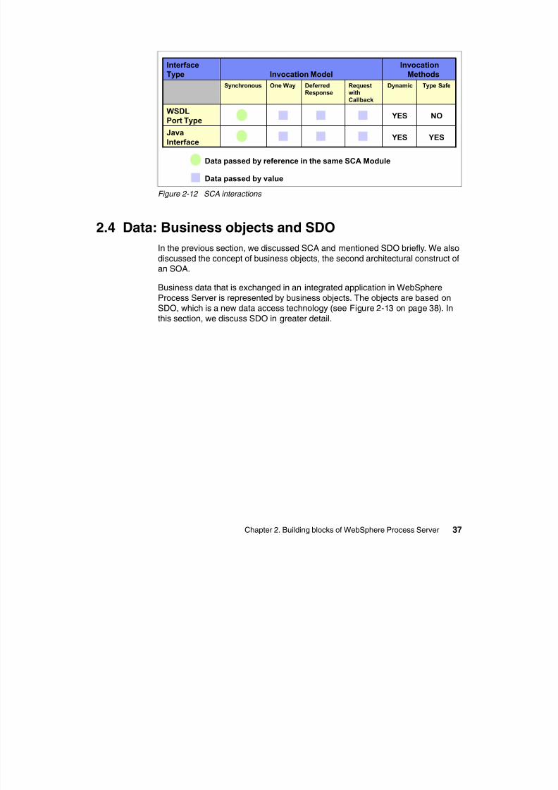
8/6/2019 WID RedBooks
http://slidepdf.com/reader/full/wid-redbooks 47/128
Chapter 2. Building blocks of WebSphere Process Server 37
Figure 2-12 SCA interactions
2.4 Data: Business objects and SDO
In the previous section, we discussed SCA and mentioned SDO briefly. We also
discussed the concept of business objects, the second architectural construct ofan SOA.
Business data that is exchanged in an integrated application in WebSphereProcess Server is represented by business objects. The objects are based onSDO, which is a new data access technology (see Figure 2-13 on page 38). In
this section, we discuss SDO in greater detail.
YES YESJava
Interface
NO YESWSDL
Port Type
Type SafeDynamicRequestwith
Callback
DeferredResponse
One WaySynchronous
Invocation
MethodsInvocation Model
Interface
Type
Data passed by reference in the same SCA Module
Data passed by value
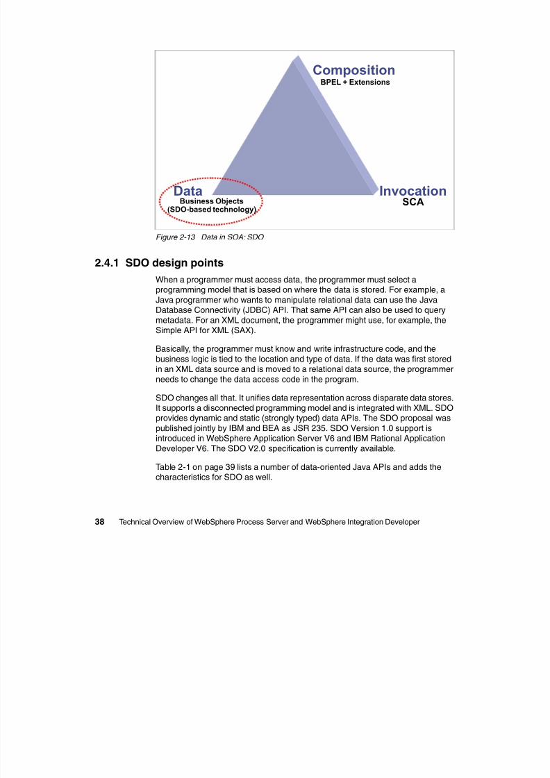
8/6/2019 WID RedBooks
http://slidepdf.com/reader/full/wid-redbooks 48/128
38 Technical Overview of WebSphere Process Server and WebSphere Integration Developer
Figure 2-13 Data in SOA: SDO
2.4.1 SDO design points
When a programmer must access data, the programmer must select aprogramming model that is based on where the data is stored. For example, a
Java programmer who wants to manipulate relational data can use the JavaDatabase Connectivity (JDBC) API. That same API can also be used to query
metadata. For an XML document, the programmer might use, for example, theSimple API for XML (SAX).
Basically, the programmer must know and write infrastructure code, and the
business logic is tied to the location and type of data. If the data was first stored
in an XML data source and is moved to a relational data source, the programmerneeds to change the data access code in the program.
SDO changes all that. It unifies data representation across disparate data stores.It supports a disconnected programming model and is integrated with XML. SDOprovides dynamic and static (strongly typed) data APIs. The SDO proposal was
published jointly by IBM and BEA as JSR 235. SDO Version 1.0 support isintroduced in WebSphere Application Server V6 and IBM Rational Application
Developer V6. The SDO V2.0 specification is currently available.
Table 2-1 on page 39 lists a number of data-oriented Java APIs and adds thecharacteristics for SDO as well.
SCABusiness Objects(SDO-based technology)
BPEL + Extensions
Data Invocation
Composition
Table 2-1 Comparing data-oriented Java APIs
Technology Model API Data Source Meta-data API Query
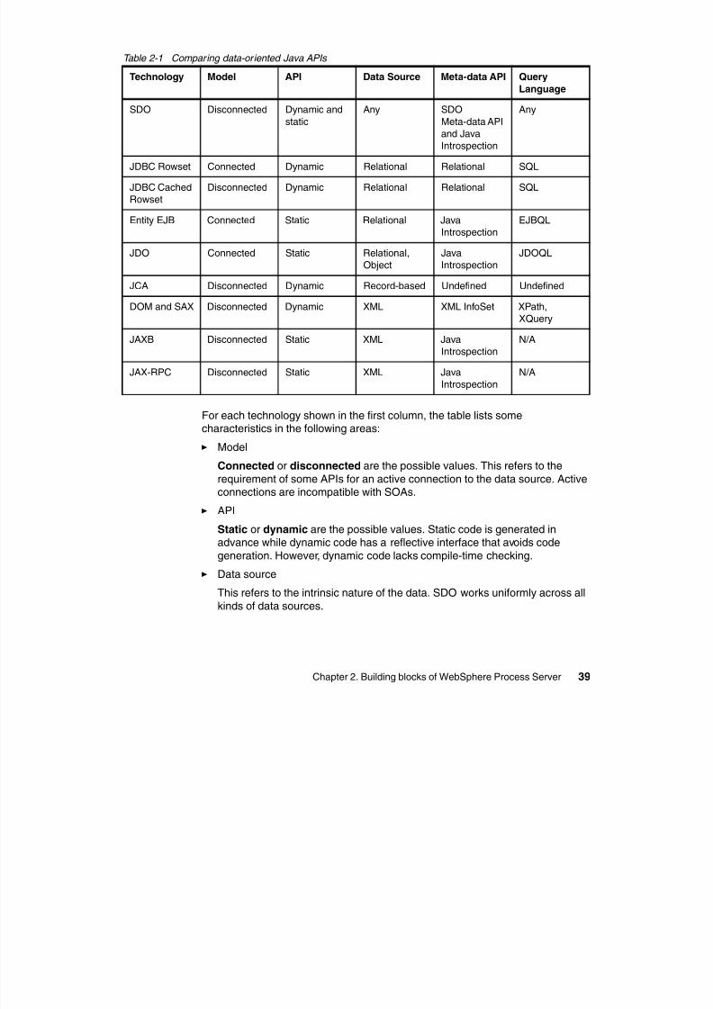
8/6/2019 WID RedBooks
http://slidepdf.com/reader/full/wid-redbooks 49/128
Chapter 2. Building blocks of WebSphere Process Server 39
For each technology shown in the first column, the table lists somecharacteristics in the following areas:
Model
Connected or disconnected are the possible values. This refers to the
requirement of some APIs for an active connection to the data source. Activeconnections are incompatible with SOAs.
API
Static or dynamic are the possible values. Static code is generated inadvance while dynamic code has a reflective interface that avoids code
generation. However, dynamic code lacks compile-time checking.
Data source
This refers to the intrinsic nature of the data. SDO works uniformly across all
kinds of data sources.
Language
SDO Disconnected Dynamic and
static
Any SDO
Meta-data API
and JavaIntrospection
Any
JDBC Rowset Connected Dynamic Relational Relational SQL
JDBC Cached
Rowset
Disconnected Dynamic Relational Relational SQL
Entity EJB Connected Static Relational Java
Introspection
EJBQL
JDO Connected Static Relational,
Object
Java
Introspection
JDOQL
JCA Disconnected Dynamic Record-based Undefined Undefined
DOM and SAX Disconnected Dynamic XML XML InfoSet XPath,
XQuery
JAXB Disconnected Static XML Java
Introspection
N/A
JAX-RPC Disconnected Static XML Java
Introspection
N/A
Meta-data API
This refers to the API that can be used to obtain type information about thef
8/6/2019 WID RedBooks
http://slidepdf.com/reader/full/wid-redbooks 50/128
40 Technical Overview of WebSphere Process Server and WebSphere Integration Developer
data itself.
Query Language
This column specifies what option is available for defining the data that isaccessed by a service. SDO can handle any query language.
In addition to providing a programming model that unifies data access, there areseveral other key design features to note about SDO. First, built into the SDO
architecture is support for some common programming patterns. Mostsignificantly, SDO supports a disconnected programming model. Typically, withthis type of pattern, a client might be disconnected from a particular data access
service (DAS) while working with a set of business data. However, when the
client has completed processing and needs to apply changes to a back-end datastore by way of a DAS, a change summary is necessary to provide theappropriate level of data concurrency control. This change summary information
has been built into the SDO programming model to support this common dataaccess scenario.
Another important design point to note is that SDO integrates well with XML. As aresult, SDO naturally fits in with distributed service-oriented applications where
XML plays a very important role.
Finally, SDO has been designed to support both dynamic and static data accessAPIs. The dynamic APIs are provided with the SDO object model and provide an
interface that allows developers to access data even when the schema of thedata is not known until runtime. In contrast to this, the static data APIs are used
when the data schema is known at development time, and the developer prefersto work with strongly typed data access APIs.
2.4.2 Some SDO concepts
There are a a few key SDO concepts that can provide a framework forunderstanding business object architecture, including the design and use of
business objects in WebSphere Process Server.
The fundamental concept in the SDO architecture is the data object. In fact, the
term SDO is often used interchangeably with the term data object. A data objectis a data structure that holds primitive data, multi-valued fields (other dataobjects), or both. The data object also has references to metadata that provide
information about the data found in the data object. In the SDO programmingmodel, data objects are represented by the commonj.sdo.DataObject Java
interface definition. This interface includes method definitions that allow clients toobtain and set the properties associated with DataObject.
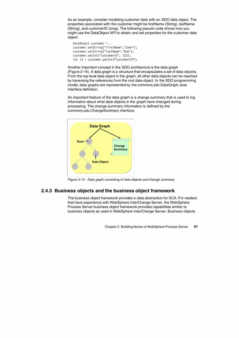
8/6/2019 WID RedBooks
http://slidepdf.com/reader/full/wid-redbooks 51/128
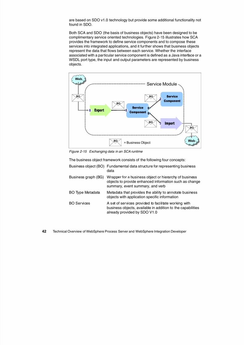
8/6/2019 WID RedBooks
http://slidepdf.com/reader/full/wid-redbooks 52/128
Note: The term business object is occasionally used to refer to the entireframework. However, in this paper, the term refers to the fundamental data
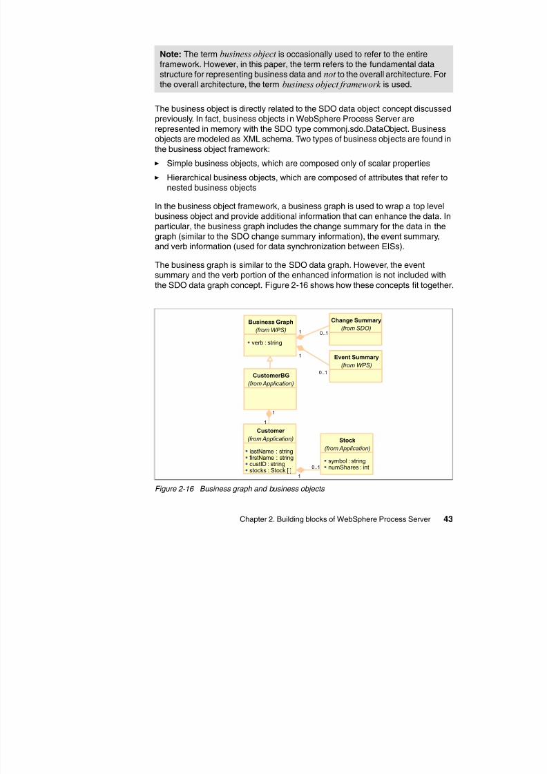
8/6/2019 WID RedBooks
http://slidepdf.com/reader/full/wid-redbooks 53/128
Chapter 2. Building blocks of WebSphere Process Server 43
The business object is directly related to the SDO data object concept discussedpreviously. In fact, business objects in WebSphere Process Server are
represented in memory with the SDO type commonj.sdo.DataObject. Businessobjects are modeled as XML schema. Two types of business objects are found in
the business object framework:
Simple business objects, which are composed only of scalar properties
Hierarchical business objects, which are composed of attributes that refer to
nested business objects
In the business object framework, a business graph is used to wrap a top levelbusiness object and provide additional information that can enhance the data. In
particular, the business graph includes the change summary for the data in thegraph (similar to the SDO change summary information), the event summary,and verb information (used for data synchronization between EISs).
The business graph is similar to the SDO data graph. However, the eventsummary and the verb portion of the enhanced information is not included with
the SDO data graph concept. Figure 2-16 shows how these concepts fit together.
Figure 2-16 Business graph and business objects
structure for representing business data and not to the overall architecture. Forthe overall architecture, the term business object framework is used.
Change Summary
(from SDO)
Event Summary
(from WPS)
CustomerBG
(from Application)
0..1
0..1
1
1
Customer
(from Application)
lastName : string firstName : string custID : string stocks : Stock [ ]
1
1
Stock
(from Application)
symbol : string numShares : int0..1
1
Business Graph
(from WPS)
verb : string
At the bottom of the graph is the simple business object, Stock . This businessobject has only scalar attributes. The business object Customer is a hierarchical
business object. It has scalar attributes, but it also has an attribute that is an
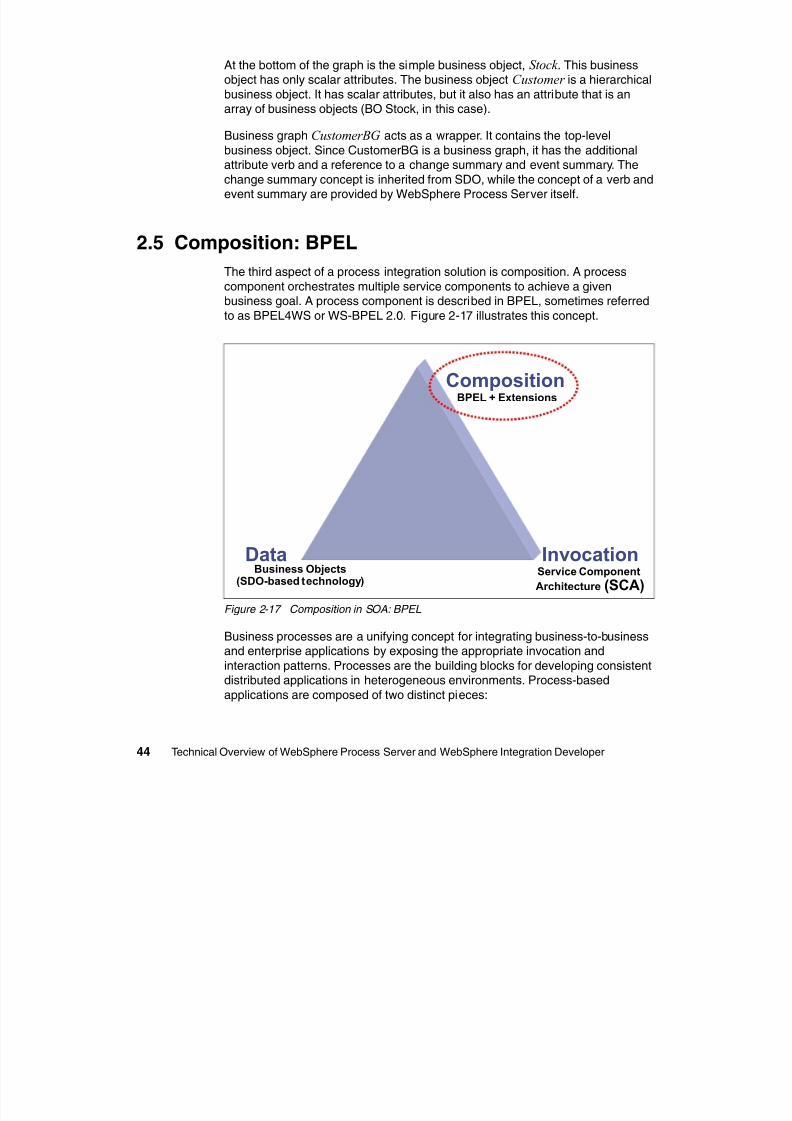
8/6/2019 WID RedBooks
http://slidepdf.com/reader/full/wid-redbooks 54/128
44 Technical Overview of WebSphere Process Server and WebSphere Integration Developer
array of business objects (BO Stock, in this case).
Business graph CustomerBG acts as a wrapper. It contains the top-level
business object. Since CustomerBG is a business graph, it has the additionalattribute verb and a reference to a change summary and event summary. The
change summary concept is inherited from SDO, while the concept of a verb andevent summary are provided by WebSphere Process Server itself.
2.5 Composition: BPEL
The third aspect of a process integration solution is composition. A processcomponent orchestrates multiple service components to achieve a givenbusiness goal. A process component is described in BPEL, sometimes referred
to as BPEL4WS or WS-BPEL 2.0. Figure 2-17 illustrates this concept.
Figure 2-17 Composition in SOA: BPEL
Business processes are a unifying concept for integrating business-to-businessand enterprise applications by exposing the appropriate invocation and
interaction patterns. Processes are the building blocks for developing consistentdistributed applications in heterogeneous environments. Process-based
applications are composed of two distinct pieces:
Service Component
Architecture (SCA)
Business Objects(SDO-based technology)
BPEL + Extensions
Data Invocation
Composition
A process model that describes the logical order in which the differentactivities of the process are being executed
The individual services/components that implement the specific activities
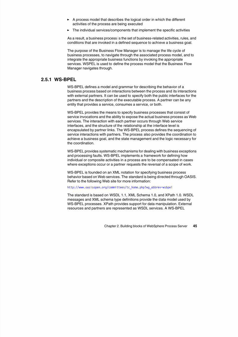
8/6/2019 WID RedBooks
http://slidepdf.com/reader/full/wid-redbooks 55/128
Chapter 2. Building blocks of WebSphere Process Server 45
p p p
As a result, a business process is the set of business-related activities, rules, and
conditions that are invoked in a defined sequence to achieve a business goal.
The purpose of the Business Flow Manager is to manage the life cycle of
business processes, to navigate through the associated process model, and tointegrate the appropriate business functions by invoking the appropriate
services. WSPEL is used to define the process model that the Business FlowManager navigates through.
2.5.1 WS-BPEL
WS-BPEL defines a model and grammar for describing the behavior of abusiness process based on interactions between the process and its interactions
with external partners. It can be used to specify both the public interfaces for thepartners and the description of the executable process. A partner can be any
entity that provides a service, consumes a service, or both.
WS-BPEL provides the means to specify business processes that consist of
service invocations and the ability to expose the actual business process as Web
services. The interaction with each partner occurs through Web serviceinterfaces, and the structure of the relationship at the interface level isencapsulated by partner links. The WS-BPEL process defines the sequencing of
service interactions with partners. The process also provides the coordination toachieve a business goal, and the state management and the logic necessary forthe coordination.
WS-BPEL provides systematic mechanisms for dealing with business exceptionsand processing faults. WS-BPEL implements a framework for defining how
individual or composite activities in a process are to be compensated in caseswhere exceptions occur or a partner requests the reversal of a scope of work.
WS-BPEL is founded on an XML notation for specifying business process
behavior based on Web services. The standard is being directed through OASIS.Refer to the following Web site for more information:
http://www.oasisopen.org/committees/tc_home.php?wg_abbrev=wsbpel
The standard is based on WSDL 1.1, XML Schema 1.0, and XPath 1.0. WSDL
messages and XML schema type definitions provide the data model used byWS-BPEL processes. XPath provides support for data manipulation. Externalresources and partners are represented as WSDL services. A WS-BPEL
compliant process can be executed in any process execution environment thatsupports that standard. Therefore, WS-BPEL process models are portable.
The technical features of WS-BPEL are:
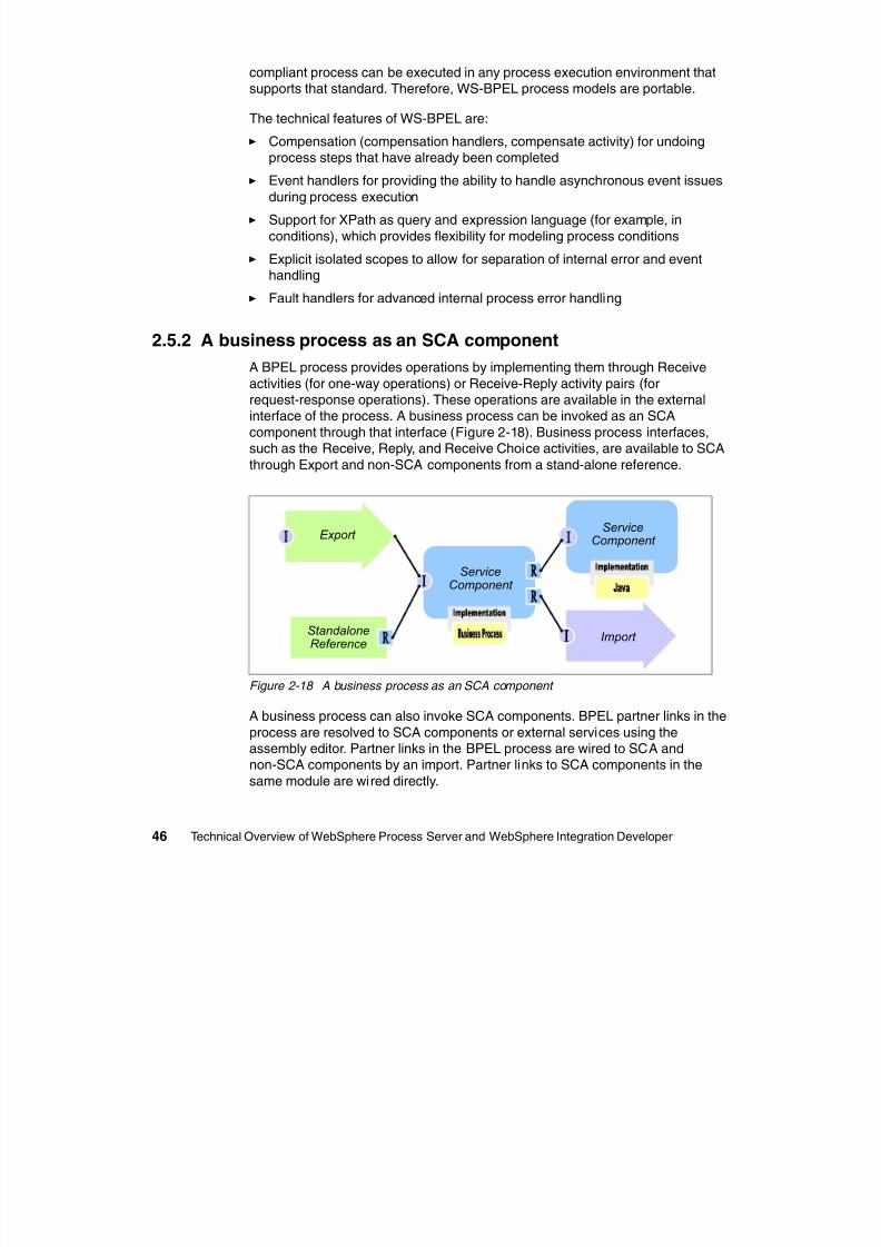
8/6/2019 WID RedBooks
http://slidepdf.com/reader/full/wid-redbooks 56/128
46 Technical Overview of WebSphere Process Server and WebSphere Integration Developer
The technical features of WS-BPEL are:
Compensation (compensation handlers, compensate activity) for undoing
process steps that have already been completed Event handlers for providing the ability to handle asynchronous event issues
during process execution
Support for XPath as query and expression language (for example, in
conditions), which provides flexibility for modeling process conditions
Explicit isolated scopes to allow for separation of internal error and eventhandling
Fault handlers for advanced internal process error handling
2.5.2 A business process as an SCA component
A BPEL process provides operations by implementing them through Receive
activities (for one-way operations) or Receive-Reply activity pairs (forrequest-response operations). These operations are available in the externalinterface of the process. A business process can be invoked as an SCA
component through that interface (Figure 2-18). Business process interfaces,
such as the Receive, Reply, and Receive Choice activities, are available to SCAthrough Export and non-SCA components from a stand-alone reference.
Figure 2-18 A business process as an SCA component
A business process can also invoke SCA components. BPEL partner links in the
process are resolved to SCA components or external services using the
assembly editor. Partner links in the BPEL process are wired to SCA andnon-SCA components by an import. Partner links to SCA components in the
same module are wired directly.
Import
Export
StandaloneReference
ServiceComponent
ServiceComponent
A BPEL process uses an invoke activity to invoke other services. That activityspecifies the partner and the operation that is to be called on behalf of the
process, the data that is used as the input message to that operation, and, in thecase of a request-response operation where the result data is to be stored
8/6/2019 WID RedBooks
http://slidepdf.com/reader/full/wid-redbooks 57/128
Chapter 2. Building blocks of WebSphere Process Server 47
case of a request-response operation, where the result data is to be stored.
BPEL processes can transparently handle one-way, request-response
operations, and synchronous and asynchronous interaction modes, using thesame syntax for all cases. The business flow manager dynamically detects the
type of service implemented by the corresponding partner and uses theappropriate invocation. This allows the business process modeler to create
processes that are independent from the physical realization of the involvedservices.
Business processes execute in a dedicated container, the Business FlowManager component of Business Process Choreographer. This component
persistently and reliably:
Manages process state Routes incoming requests to the correct instance Executes BPEL statements Interfaces with the Human Task Manager for people interactions Produces the right logging events for the Common Event Infrastructure (CEI) Deploys and manages processes
2.5.3 Business process examplesBusiness processes are used to solve a wide variety of business problems.
WebSphere Process Server implements functionality that maps to features thatare available in WebSphere Business Integration Server Foundation, WebSphere
InterChange Server, and WebSphere MQ Workflow. WebSphere Process Serverprovides techniques for building solutions that mimic the functionality that isavailable in each of these earlier products. This section briefly describes how
these tools provide business process support to illustrate the advanced
architecture of WebSphere Process Server.
WebSphere Business Integration Server FoundationWebSphere Process Server is a direct evolution from WebSphere Business
Integration Server Foundation. As such, the business process model that isavailable in WebSphere Business Integration Server Foundation is supported
and extended in WebSphere Process Server.
Figure 2-19 on page 48 shows a simple WebSphere Process Server solution that
represents a WebSphere Business Integration Server Foundation solution. Onthe left is a Web services export that exposes the service as a standard Web
service. The business process is a WS-BPEL-based solution that integratespartner links that are exposed as references and implemented as Web services.
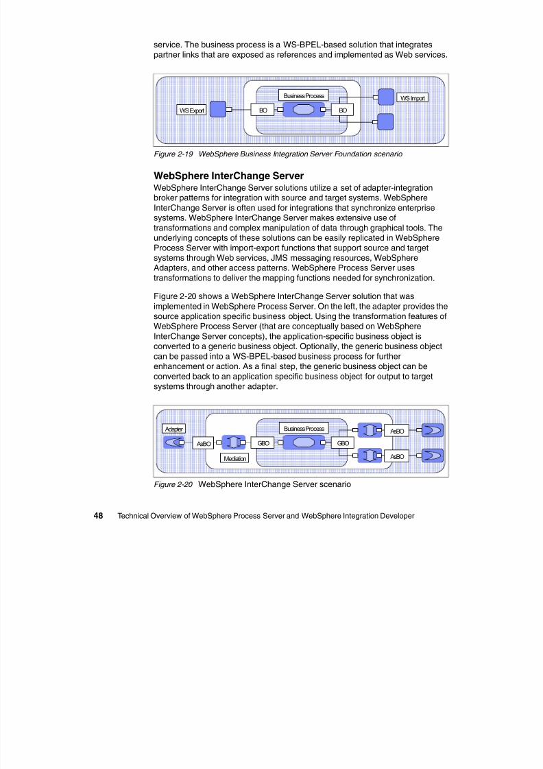
8/6/2019 WID RedBooks
http://slidepdf.com/reader/full/wid-redbooks 58/128
48 Technical Overview of WebSphere Process Server and WebSphere Integration Developer
Figure 2-19 WebSphere Business Integration Server Foundation scenario
WebSphere InterChange Server
WebSphere InterChange Server solutions utilize a set of adapter-integrationbroker patterns for integration with source and target systems. WebSphere
InterChange Server is often used for integrations that synchronize enterprisesystems. WebSphere InterChange Server makes extensive use of
transformations and complex manipulation of data through graphical tools. Theunderlying concepts of these solutions can be easily replicated in WebSphere
Process Server with import-export functions that support source and targetsystems through Web services, JMS messaging resources, WebSphereAdapters, and other access patterns. WebSphere Process Server uses
transformations to deliver the mapping functions needed for synchronization.
Figure 2-20 shows a WebSphere InterChange Server solution that was
implemented in WebSphere Process Server. On the left, the adapter provides thesource application specific business object. Using the transformation features ofWebSphere Process Server (that are conceptually based on WebSphere
InterChange Server concepts), the application-specific business object isconverted to a generic business object. Optionally, the generic business object
can be passed into a WS-BPEL-based business process for furtherenhancement or action. As a final step, the generic business object can be
converted back to an application specific business object for output to targetsystems through another adapter.
Figure 2-20 WebSphere InterChange Server scenario
BO BOWS Export
Business Process WS Import
AsBO GBO
AsBO
AsBO
GBO
Mediation
Adapter Business Process
WebSphere MQ WorkflowWebSphere MQ Workflow is a WebSphere MQ-based workflow solution. Many of
the human-related features of the Human Task Manager are derived fromWebSphere MQ Workflow Figure 2-21 shows a simple example of a JMS export
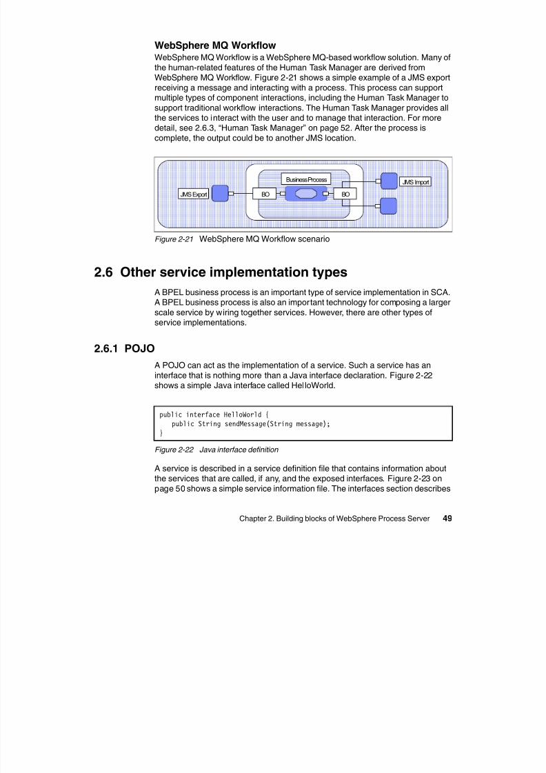
8/6/2019 WID RedBooks
http://slidepdf.com/reader/full/wid-redbooks 59/128
Chapter 2. Building blocks of WebSphere Process Server 49
WebSphere MQ Workflow. Figure 2-21 shows a simple example of a JMS export
receiving a message and interacting with a process. This process can supportmultiple types of component interactions, including the Human Task Manager to
support traditional workflow interactions. The Human Task Manager provides allthe services to interact with the user and to manage that interaction. For moredetail, see 2.6.3, “Human Task Manager” on page 52. After the process is
complete, the output could be to another JMS location.
Figure 2-21 WebSphere MQ Workflow scenario
2.6 Other service implementation types
A BPEL business process is an important type of service implementation in SCA.A BPEL business process is also an important technology for composing a larger
scale service by wiring together services. However, there are other types ofservice implementations.
2.6.1 POJO
A POJO can act as the implementation of a service. Such a service has an
interface that is nothing more than a Java interface declaration. Figure 2-22 shows a simple Java interface called HelloWorld.
Figure 2-22 Java interface definition
A service is described in a service definition file that contains information aboutthe services that are called, if any, and the exposed interfaces. Figure 2-23 on
page 50 shows a simple service information file. The interfaces section describes
BO BOJMS Export
Business Process JMS Import
public interface HelloWorld {public String sendMessage(String message);
}
the exposed interfaces, while the implementation section lists the Java class thatimplements this service.
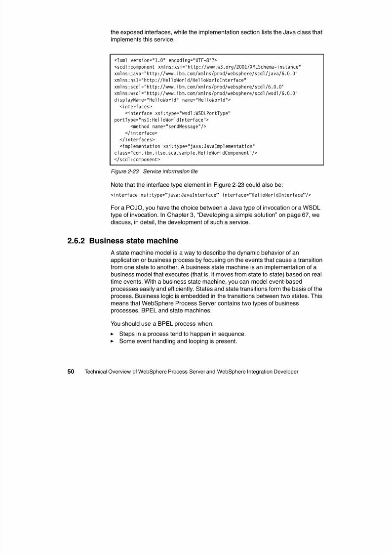
8/6/2019 WID RedBooks
http://slidepdf.com/reader/full/wid-redbooks 60/128
50 Technical Overview of WebSphere Process Server and WebSphere Integration Developer
Figure 2-23 Service information file
Note that the interface type element in Figure 2-23 could also be:
<interface xsi:type=”java:JavaInterface” interface=”HelloWorldInterface”/>
For a POJO, you have the choice between a Java type of invocation or a WSDLtype of invocation. In Chapter 3, “Developing a simple solution” on page 67, we
discuss, in detail, the development of such a service.
2.6.2 Business state machine
A state machine model is a way to describe the dynamic behavior of an
application or business process by focusing on the events that cause a transition
from one state to another. A business state machine is an implementation of abusiness model that executes (that is, it moves from state to state) based on realtime events. With a business state machine, you can model event-based
processes easily and efficiently. States and state transitions form the basis of theprocess. Business logic is embedded in the transitions between two states. This
means that WebSphere Process Server contains two types of businessprocesses, BPEL and state machines.
You should use a BPEL process when:
Steps in a process tend to happen in sequence. Some event handling and looping is present.
<?xml version="1.0" encoding="UTF-8"?><scdl:component xmlns:xsi="http://www.w3.org/2001/XMLSchema-instance"
xmlns:java="http://www.ibm.com/xmlns/prod/websphere/scdl/java/6.0.0"xmlns:ns1="http://HelloWorld/HelloWorldInterface"xmlns:scdl="http://www.ibm.com/xmlns/prod/websphere/scdl/6.0.0"xmlns:wsdl="http://www.ibm.com/xmlns/prod/websphere/scdl/wsdl/6.0.0"displayName="HelloWorld" name="HelloWorld">
<interfaces><interface xsi:type="wsdl:WSDLPortType"
portType="ns1:HelloWorldInterface"><method name="sendMessage"/>
</interface>
</interfaces><implementation xsi:type="java:JavaImplementation"
class="com.ibm.itso.sca.sample.HelloWorldComponent"/></scdl:component>
You should use a business state machine when:
The business process is heavily event-driven. The reaction to these events is dependent on the process state. The process may revert to prior states
8/6/2019 WID RedBooks
http://slidepdf.com/reader/full/wid-redbooks 61/128
Chapter 2. Building blocks of WebSphere Process Server 51
The process may revert to prior states. Some sequential steps are involved.
A good example of a business process that is easily modeled as a state machineis an ordering process where the buyer can cancel or modify the order at anytime. The cancel or modify could become an event that can occur at any time in
the state machine and that needs to be handled in the design. If an order cannotbe modified or canceled again after it has been submitted, you might as well
model the order processing as a generic BPEL process.
Note that at runtime, a process that is modeled as a state machine is stilldescribed as a BPEL process. The process is deployed to the same business
process engine that is used for ordinary BPEL processes. The main differencebetween a business state machine and a BPEL process is noticeable at
modeling time. One technology is better suited for a certain class of businessprocesses than another. But at runtime, the difference is minimal.
When discussing state machines, a number of terms are often used and theyhave specific meaning in the context of state machines:
States A state is one of several discrete individual stages that are
organized in sequence to create a business transaction.Composite states A composite state is an aggregate of one or more states
that can be used to decompose a complex state machinediagram into an easy to comprehend hierarchy.
Operations/events An operation is an external prompt that attempts to trigger
a movement from one state to another.
Transitions A transition is the movement that occurs through the
recognition of an appropriate triggering operation, the
evaluation of the conditions necessary for execution toflow through it, and the determination of what actions canoccur should execution be allowed.
Conditions A condition guards the transition and only allows the
transition to the next state if the incoming operationevaluates to True. Otherwise, the current state is
maintained.
Actions An action is an operation that is executed at one of three
distinct locations in the business state machine: during atransition, when a state is entered, or when a state is
exited.
Correlation The state machine uses correlations to distinguish theparties in their initial interactions so that they can
recognize each other in the future. A correlation is therecord that is used to keep track of multiple participants in
h b i i
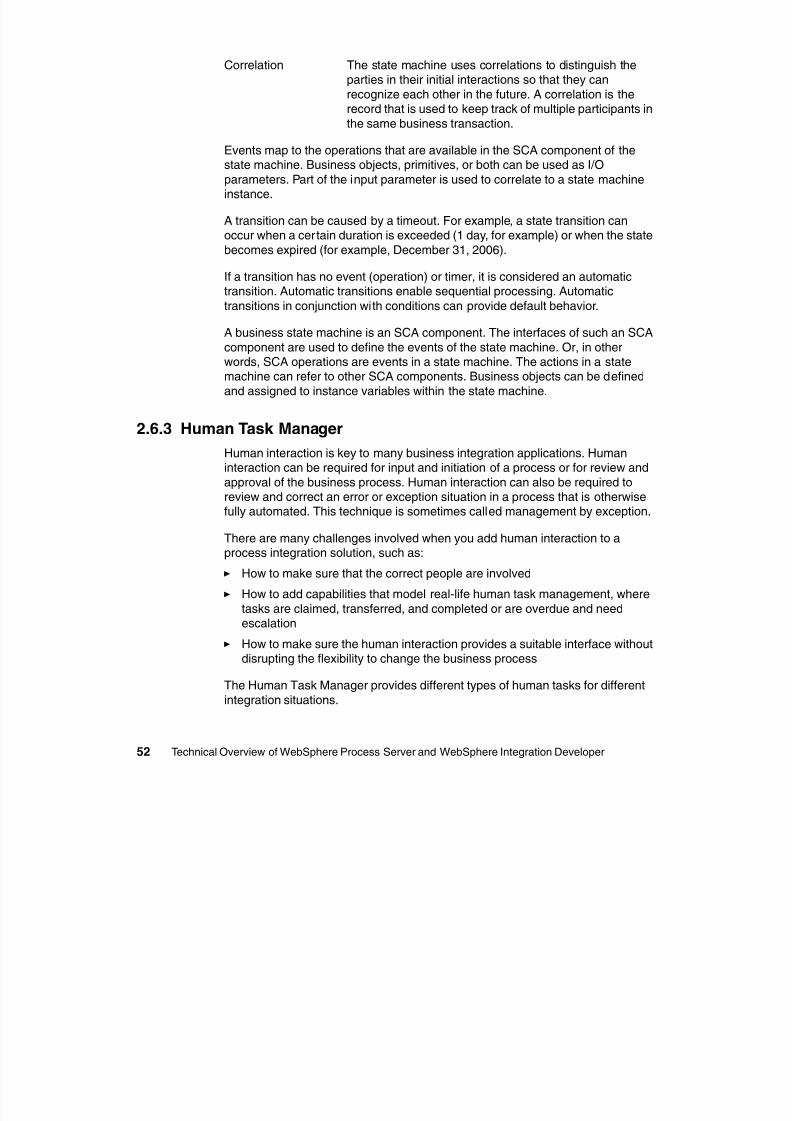
8/6/2019 WID RedBooks
http://slidepdf.com/reader/full/wid-redbooks 62/128
52 Technical Overview of WebSphere Process Server and WebSphere Integration Developer
the same business transaction.
Events map to the operations that are available in the SCA component of thestate machine. Business objects, primitives, or both can be used as I/O
parameters. Part of the input parameter is used to correlate to a state machineinstance.
A transition can be caused by a timeout. For example, a state transition canoccur when a certain duration is exceeded (1 day, for example) or when the state
becomes expired (for example, December 31, 2006).
If a transition has no event (operation) or timer, it is considered an automatictransition. Automatic transitions enable sequential processing. Automatic
transitions in conjunction with conditions can provide default behavior.
A business state machine is an SCA component. The interfaces of such an SCA
component are used to define the events of the state machine. Or, in otherwords, SCA operations are events in a state machine. The actions in a statemachine can refer to other SCA components. Business objects can be defined
and assigned to instance variables within the state machine.
2.6.3 Human Task Manager
Human interaction is key to many business integration applications. Humaninteraction can be required for input and initiation of a process or for review and
approval of the business process. Human interaction can also be required toreview and correct an error or exception situation in a process that is otherwisefully automated. This technique is sometimes called management by exception.
There are many challenges involved when you add human interaction to aprocess integration solution, such as:
How to make sure that the correct people are involved
How to add capabilities that model real-life human task management, where
tasks are claimed, transferred, and completed or are overdue and needescalation
How to make sure the human interaction provides a suitable interface withoutdisrupting the flexibility to change the business process
The Human Task Manager provides different types of human tasks for different
integration situations.
Participating Task A service creates a work item for human interaction (forexample, a service implemented in BPEL).
Originating Task Human interaction invokes a service (for example, a
business state machine).
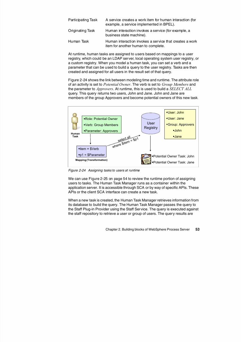
8/6/2019 WID RedBooks
http://slidepdf.com/reader/full/wid-redbooks 63/128
Chapter 2. Building blocks of WebSphere Process Server 53
)
Human Task Human interaction invokes a service that creates a work
item for another human to complete.
At runtime, human tasks are assigned to users based on mappings to a userregistry, which could be an LDAP server, local operating system user registry, or
a custom registry. When you model a human task, you can set a verb and aparameter that can be used to build a query to the user registry. Tasks are thencreated and assigned for all users in the result set of that query.
Figure 2-24 shows the link between modeling time and runtime. The attribute role
of an activity is set to Potential Owner . The verb is set to Group Members andthe parameter to Approvers. At runtime, this is used to build a SELECT ALL query. This query returns two users, John and Jane. John and Jane aremembers of the group Approvers and become potential owners of this new task.
Figure 2-24 Assigning tasks to users at runtime
We can use Figure 2-25 on page 54 to review the runtime portion of assigning
users to tasks. The Human Task Manager runs as a container within theapplication server. It is accessible through SCA or by way of specific APIs. TheseAPIs or the client SCA interface can create a new task.
When a new task is created, the Human Task Manager retrieves information from
its database to build the query. The Human Task Manager passes the query tothe Staff Plug-in Provider using the Staff Service. The query is executed againstthe staff repository to retrieve a user or group of users. The query results are
User Registry
User: John
User: Jane
Group: ApproversJohn
Jane
Role: Potential Owner
Verb: Group MembersParameter: Approvers
item = $Verb
p1 = $Parameter
HumanTask
Potential Owner Task: John
Potential Owner Task: Jane
s e l e c t a
l l
w h e r e $
i t e m = $
p 1
Mapping (Transformation)
returned to the Human Task Manager. The new tasks that are created for theselected users are then stored in the database by the Human Task Manager.
Staff plug-in providers are managed as resources in the application server andare accessible through the Java Naming and Directory Interface (JNDI)
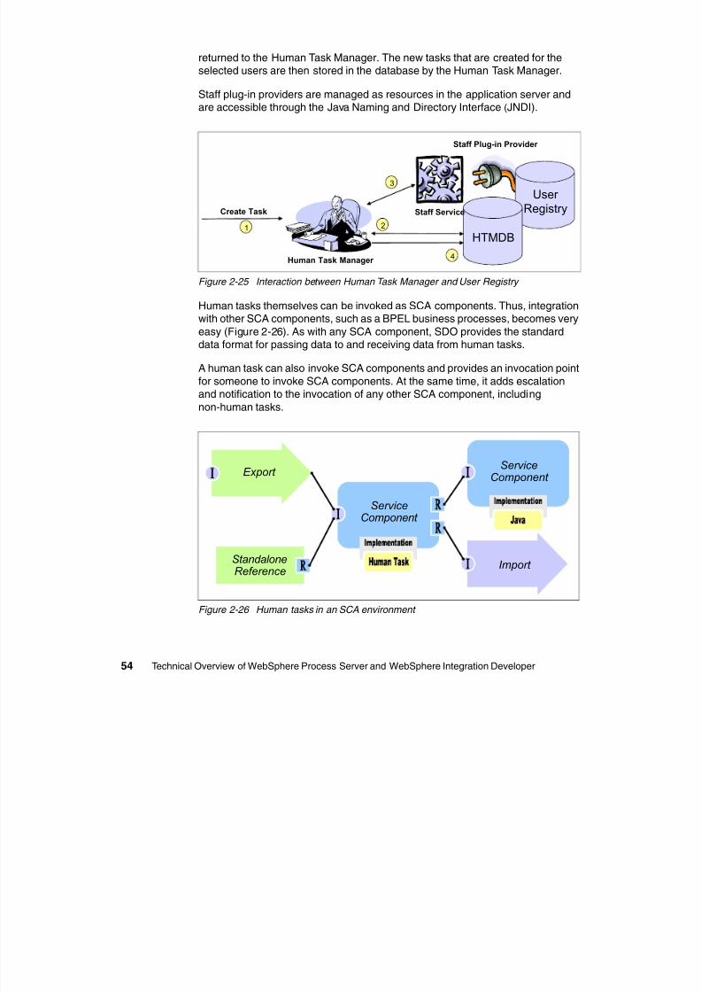
8/6/2019 WID RedBooks
http://slidepdf.com/reader/full/wid-redbooks 64/128
54 Technical Overview of WebSphere Process Server and WebSphere Integration Developer
are accessible through the Java Naming and Directory Interface (JNDI).
Figure 2-25 Interaction between Human Task Manager and User Registry
Human tasks themselves can be invoked as SCA components. Thus, integrationwith other SCA components, such as a BPEL business processes, becomes very
easy (Figure 2-26). As with any SCA component, SDO provides the standarddata format for passing data to and receiving data from human tasks.
A human task can also invoke SCA components and provides an invocation pointfor someone to invoke SCA components. At the same time, it adds escalationand notification to the invocation of any other SCA component, including
non-human tasks.
Figure 2-26 Human tasks in an SCA environment
User Registry
HTMDB
Staff Service
Human Task Manager
2
3
4
Create Task
1
Staff Plug-in Provider
Import
Export
StandaloneReference
ServiceComponent
Service
Component
2.6.4 Business rules
Business rule groups are a means of implementing and enforcing business policythrough the externalization of business functions. Externalization allows thebusiness rules to be managed independently from other aspects of an
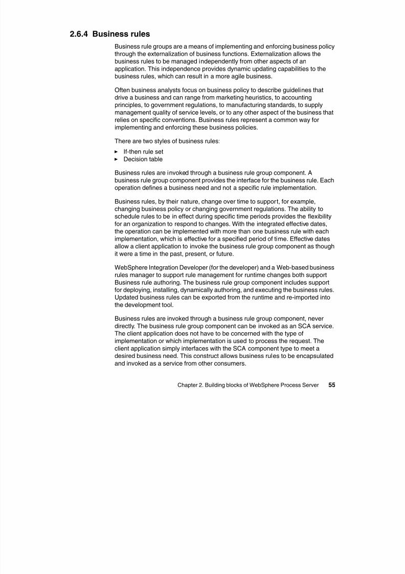
8/6/2019 WID RedBooks
http://slidepdf.com/reader/full/wid-redbooks 65/128
Chapter 2. Building blocks of WebSphere Process Server 55
g p y p
application. This independence provides dynamic updating capabilities to the
business rules, which can result in a more agile business.
Often business analysts focus on business policy to describe guidelines thatdrive a business and can range from marketing heuristics, to accountingprinciples, to government regulations, to manufacturing standards, to supply
management quality of service levels, or to any other aspect of the business thatrelies on specific conventions. Business rules represent a common way for
implementing and enforcing these business policies.
There are two styles of business rules: If-then rule set Decision table
Business rules are invoked through a business rule group component. A
business rule group component provides the interface for the business rule. Eachoperation defines a business need and not a specific rule implementation.
Business rules, by their nature, change over time to support, for example,
changing business policy or changing government regulations. The ability toschedule rules to be in effect during specific time periods provides the flexibility
for an organization to respond to changes. With the integrated effective dates,the operation can be implemented with more than one business rule with each
implementation, which is effective for a specified period of time. Effective datesallow a client application to invoke the business rule group component as though
it were a time in the past, present, or future.
WebSphere Integration Developer (for the developer) and a Web-based business
rules manager to support rule management for runtime changes both supportBusiness rule authoring. The business rule group component includes supportfor deploying, installing, dynamically authoring, and executing the business rules.Updated business rules can be exported from the runtime and re-imported into
the development tool.
Business rules are invoked through a business rule group component, never
directly. The business rule group component can be invoked as an SCA service.The client application does not have to be concerned with the type ofimplementation or which implementation is used to process the request. The
client application simply interfaces with the SCA component type to meet adesired business need. This construct allows business rules to be encapsulated
and invoked as a service from other consumers.
The business rule group component is the artifact used to interface and invokerules. As mentioned previously, rule sets and decision tables (representing the
two forms of business rules that are supported in WebSphere Process Server)are never invoked directly. The rule group component provides a means for the
user to form logical groupings of the business rules. The integrated effective
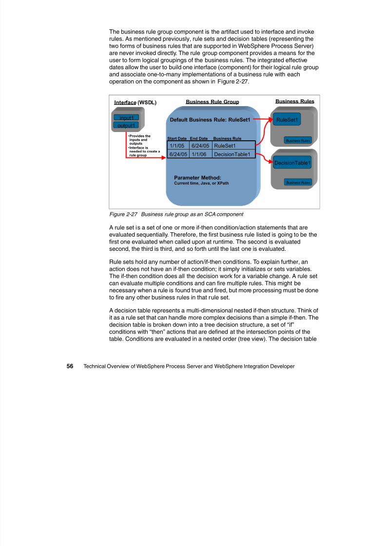
8/6/2019 WID RedBooks
http://slidepdf.com/reader/full/wid-redbooks 66/128
56 Technical Overview of WebSphere Process Server and WebSphere Integration Developer
user to form logical groupings of the business rules. The integrated effectivedates allow the user to build one interface (component) for their logical rule group
and associate one-to-many implementations of a business rule with eachoperation on the component as shown in Figure 2-27.
Figure 2-27 Business rule group as an SCA component
A rule set is a set of one or more if-then condition/action statements that areevaluated sequentially. Therefore, the first business rule listed is going to be the
first one evaluated when called upon at runtime. The second is evaluatedsecond, the third is third, and so forth until the last one is evaluated.
Rule sets hold any number of action/if-then conditions. To explain further, anaction does not have an if-then condition; it simply initializes or sets variables.The if-then condition does all the decision work for a variable change. A rule set
can evaluate multiple conditions and can fire multiple rules. This might benecessary when a rule is found true and fired, but more processing must be doneto fire any other business rules in that rule set.
A decision table represents a multi-dimensional nested if-then structure. Think ofit as a rule set that can handle more complex decisions than a simple if-then. The
decision table is broken down into a tree decision structure, a set of “if”conditions with “then” actions that are defined at the intersection points of thetable. Conditions are evaluated in a nested order (tree view). The decision table
Interface (WSDL)
input1
output1
Business Rule Group Business Rules
Default Business Rule: RuleSet1 RuleSet1
DecisionTable1
Business Rules
Business Rules
DecisionTable11/1/066/24/05
RuleSet16/24/051/1/05
Parameter Method:Current time, Java, or XPath
Start Date End Date Business Rule•Provides theinputs andoutputs
•Interface isneeded to create arule group
evaluates one or more conditions, but fires only one rule. Most rules fall under adecision tree because most business rules are called to fire one rule.
Use decision tables when:
You have rules with multiple clauses/variables in the conditional statements
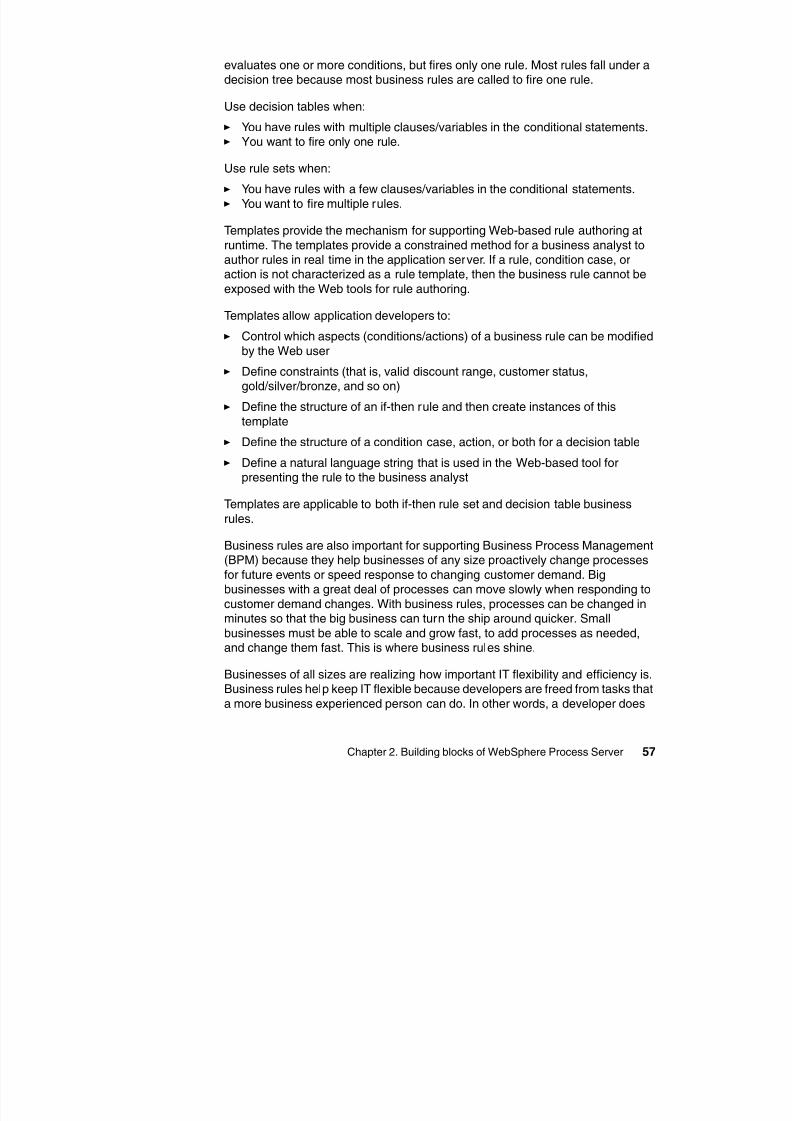
8/6/2019 WID RedBooks
http://slidepdf.com/reader/full/wid-redbooks 67/128
Chapter 2. Building blocks of WebSphere Process Server 57
You have rules with multiple clauses/variables in the conditional statements. You want to fire only one rule.
Use rule sets when:
You have rules with a few clauses/variables in the conditional statements. You want to fire multiple rules.
Templates provide the mechanism for supporting Web-based rule authoring at
runtime. The templates provide a constrained method for a business analyst toauthor rules in real time in the application server. If a rule, condition case, oraction is not characterized as a rule template, then the business rule cannot be
exposed with the Web tools for rule authoring.
Templates allow application developers to:
Control which aspects (conditions/actions) of a business rule can be modified
by the Web user
Define constraints (that is, valid discount range, customer status,gold/silver/bronze, and so on)
Define the structure of an if-then rule and then create instances of thistemplate
Define the structure of a condition case, action, or both for a decision table
Define a natural language string that is used in the Web-based tool forpresenting the rule to the business analyst
Templates are applicable to both if-then rule set and decision table business
rules.
Business rules are also important for supporting Business Process Management(BPM) because they help businesses of any size proactively change processes
for future events or speed response to changing customer demand. Bigbusinesses with a great deal of processes can move slowly when responding to
customer demand changes. With business rules, processes can be changed inminutes so that the big business can turn the ship around quicker. Small
businesses must be able to scale and grow fast, to add processes as needed,and change them fast. This is where business rules shine.
Businesses of all sizes are realizing how important IT flexibility and efficiency is.Business rules help keep IT flexible because developers are freed from tasks that
a more business experienced person can do. In other words, a developer does
not have to be bothered every time a simple rule needs to be changed. Abusiness analyst who is more in tune to business needs can make that change
swiftly. Another attribute of business rules that improve IT efficiency is the abilityto have multiple processes call a business rule at the same time. This
multi-threading allows multiple processes to run at the same time.
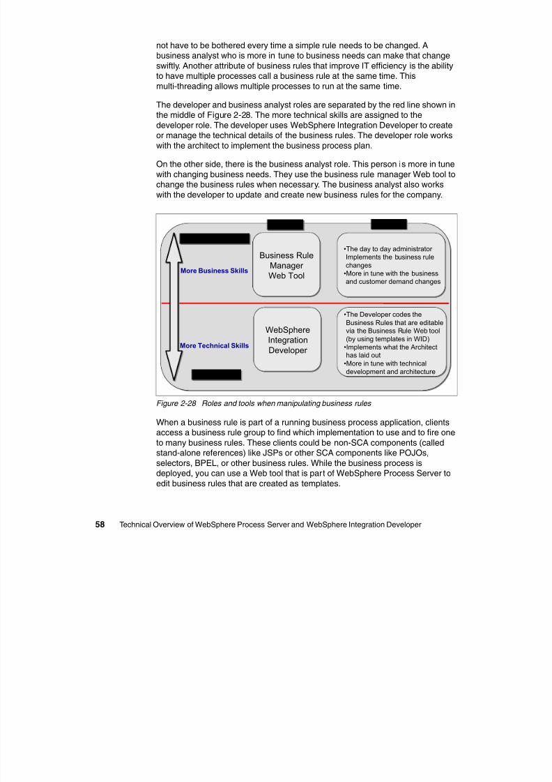
8/6/2019 WID RedBooks
http://slidepdf.com/reader/full/wid-redbooks 68/128
58 Technical Overview of WebSphere Process Server and WebSphere Integration Developer
The developer and business analyst roles are separated by the red line shown inthe middle of Figure 2-28. The more technical skills are assigned to the
developer role. The developer uses WebSphere Integration Developer to createor manage the technical details of the business rules. The developer role works
with the architect to implement the business process plan.
On the other side, there is the business analyst role. This person is more in tune
with changing business needs. They use the business rule manager Web tool tochange the business rules when necessary. The business analyst also works
with the developer to update and create new business rules for the company.
Figure 2-28 Roles and tools when manipulating business rules
When a business rule is part of a running business process application, clientsaccess a business rule group to find which implementation to use and to fire one
to many business rules. These clients could be non-SCA components (calledstand-alone references) like JSPs or other SCA components like POJOs,
selectors, BPEL, or other business rules. While the business process is
deployed, you can use a Web tool that is part of WebSphere Process Server toedit business rules that are created as templates.
Tools UsedTools Used Role TasksRole Tasks
Developer RoleDeveloper Role
Business Analyst RoleBusiness Analyst Role
More Technical Skills
WebSphereIntegrationDeveloper
WebSphereIntegrationDeveloper
Business RuleManager Web Tool
Business RuleManager Web Tool
•The day to day administrator Implements the business rulechanges
•More in tune with the businessand customer demand changes
•The day to day administrator Implements the business rulechanges
•More in tune with the businessand customer demand changes
•The Developer codes theBusiness Rules that are editablevia the Business Rule Web tool(by using templates in WID)
•Implements what the Architecthas laid out
•More in tune with technicaldevelopment and architecture
•The Developer codes theBusiness Rules that are editablevia the Business Rule Web tool(by using templates in WID)
•Implements what the Architecthas laid out
•More in tune with technicaldevelopment and architecture
More Business Skills
Business Rule Group
Web Tool
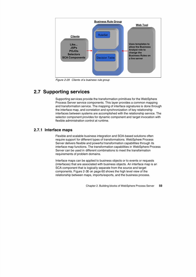
8/6/2019 WID RedBooks
http://slidepdf.com/reader/full/wid-redbooks 69/128
Chapter 2. Building blocks of WebSphere Process Server 59
Figure 2-29 Clients of a business rule group
2.7 Supporting services
Supporting services provide the transformation primitives for the WebSphere
Process Server service components. This layer provides a common mappingand transformation service. The mapping of interface signatures is done through
the interface map, and correlation and synchronization of key relationshipinterfaces between systems are accomplished with the relationship service. The
selector component provides for dynamic component and target invocation withflexible administration control at runtime.
2.7.1 Interface maps
Flexible and scalable business integration and SOA-based solutions oftenrequire support for different types of transformations. WebSphere Process
Server delivers flexible and powerful transformation capabilities through itsinterface map functions. The transformation capabilities in WebSphere Process
Server can be used in different combinations to meet the transformationrequirements of problem domains.
Interface maps can be applied to business objects or to events or requests(interfaces) that are associated with business objects. An interface map is an
SCA component that is logically separate from the source and targetcomponents. Figure 2-30 on page 60 shows the high level view of the
relationship between maps, imports/exports, and the business process.
Clients
RuleSet
Decision Table
Like...
JSPs
POJOs
Selectors
SCA Components
Uses templates to
allow the Business
Analyst role to
change the
Business Rules on
a live server
EIS2 importEIS1 export Mapping component Mapping vomponent
EIS1EIS1 EIS2EIS2
Business rocessP
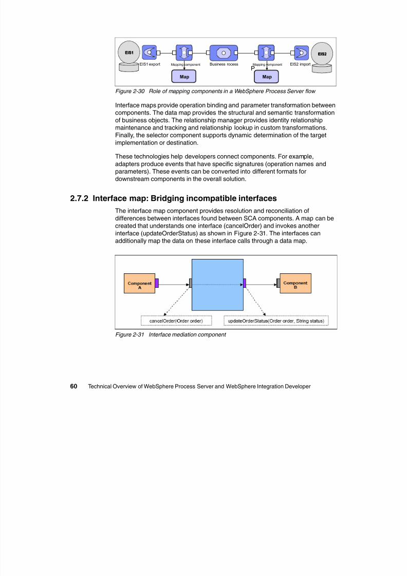
8/6/2019 WID RedBooks
http://slidepdf.com/reader/full/wid-redbooks 70/128
60 Technical Overview of WebSphere Process Server and WebSphere Integration Developer
Figure 2-30 Role of mapping components in a WebSphere Process Server flow
Interface maps provide operation binding and parameter transformation betweencomponents. The data map provides the structural and semantic transformation
of business objects. The relationship manager provides identity relationshipmaintenance and tracking and relationship lookup in custom transformations.Finally, the selector component supports dynamic determination of the target
implementation or destination.
These technologies help developers connect components. For example,
adapters produce events that have specific signatures (operation names andparameters). These events can be converted into different formats fordownstream components in the overall solution.
2.7.2 Interface map: Bridging incompatible interfaces
The interface map component provides resolution and reconciliation ofdifferences between interfaces found between SCA components. A map can becreated that understands one interface (cancelOrder) and invokes another
interface (updateOrderStatus) as shown in Figure 2-31. The interfaces canadditionally map the data on these interface calls through a data map.
Figure 2-31 Interface mediation component
Map Map
P
2.7.3 Data maps
WebSphere Integration Developer contains a rich graphical mapping tool thatoffers move, join, extract, and assign functionality for data fields and custommapping (through custom activities or Java code). It also offers sub-maps for
complex business object structures and relationship mapping.
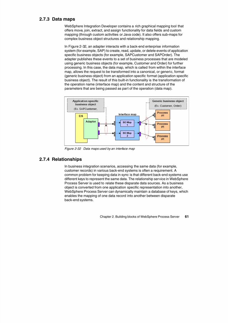
8/6/2019 WID RedBooks
http://slidepdf.com/reader/full/wid-redbooks 71/128
Chapter 2. Building blocks of WebSphere Process Server 61
complex business object structures and relationship mapping.
In Figure 2-32, an adapter interacts with a back-end enterprise information
system (for example, SAP) to create, read, update, or delete events of applicationspecific business objects (for example, SAPCustomer and SAPOrder). Theadapter publishes these events to a set of business processes that are modeled
using generic business objects (for example, Customer and Order) for furtherprocessing. In this case, the data map, which is called from within the interface
map, allows the request to be transformed into a canonical, or generic, format(generic business object) from an application specific format (application specific
business object). The result of this built-in functionality is the transformation ofthe operation name (interface map) and the content and structure of theparameters that are being passed as part of the operation (data map).
Figure 2-32 Data maps used by an interface map
2.7.4 Relationships
In business integration scenarios, accessing the same data (for example,customer records) in various back-end systems is often a requirement. A
common problem for keeping data in sync is that different back-end systems usedifferent keys to represent the same data. The relationship service in WebSphere
Process Server is used to relate these disparate data sources. As a businessobject is converted from one application specific representation into another,WebSphere Process Server can dynamically maintain a database of keys, which
enables the mapping of one data record into another between disparateback-end systems.
Figure 2-33 shows the concept of a dynamic identity relationship with a customeridentifier being maintained in four different applications. These four systems use
different identifiers and store customer information in a different format or objectmodel. A typical integration requirement is to propagate new or changed records
in all four systems. In conventional middleware solutions, this is an extremelydifficult solution to develop and more importantly to manage continuously
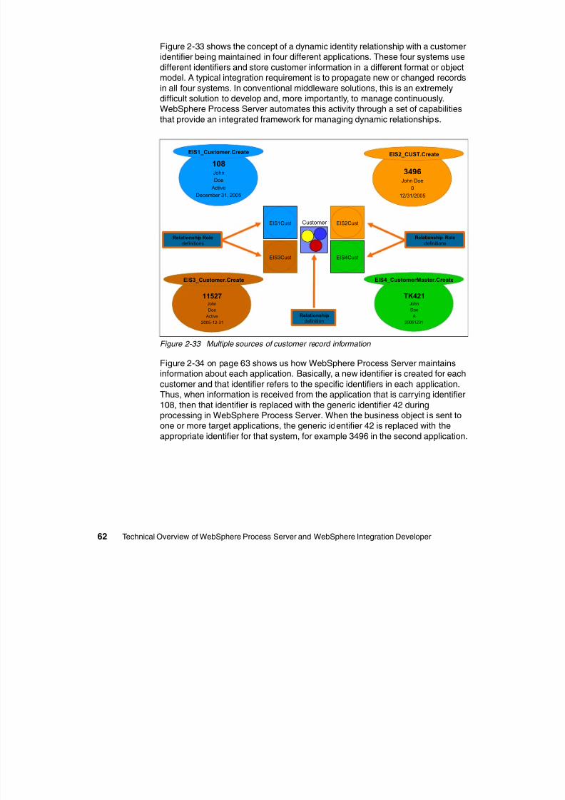
8/6/2019 WID RedBooks
http://slidepdf.com/reader/full/wid-redbooks 72/128
62 Technical Overview of WebSphere Process Server and WebSphere Integration Developer
difficult solution to develop and, more importantly, to manage continuously.
WebSphere Process Server automates this activity through a set of capabilitiesthat provide an integrated framework for managing dynamic relationships.
Figure 2-33 Multiple sources of customer record information
Figure 2-34 on page 63 shows us how WebSphere Process Server maintainsinformation about each application. Basically, a new identifier is created for each
customer and that identifier refers to the specific identifiers in each application.Thus, when information is received from the application that is carrying identifier
108, then that identifier is replaced with the generic identifier 42 duringprocessing in WebSphere Process Server. When the business object is sent toone or more target applications, the generic identifier 42 is replaced with the
appropriate identifier for that system, for example 3496 in the second application.
11527John
Doe
Active
2005-12-31
EIS3_Customer.Create
108John
Doe
Active
December 31, 2005
EIS1_Customer.Create
3496John Doe
0
12/31/2005
EIS2_CUST.Create
TK421John
Doe
A
20051231
EIS4_CustomerMaster.Create
Customer EIS2CustEIS1Cust
EIS4CustEIS3Cust
Relationship Role
definitionsRelationship Role
definitions
Relationshipdefinition
RIID CustomerId40 3494
41 3495
42 3496
43 3497
Cust_ID RIID106 40
107 41
108 42
109 43
Relationship
instance
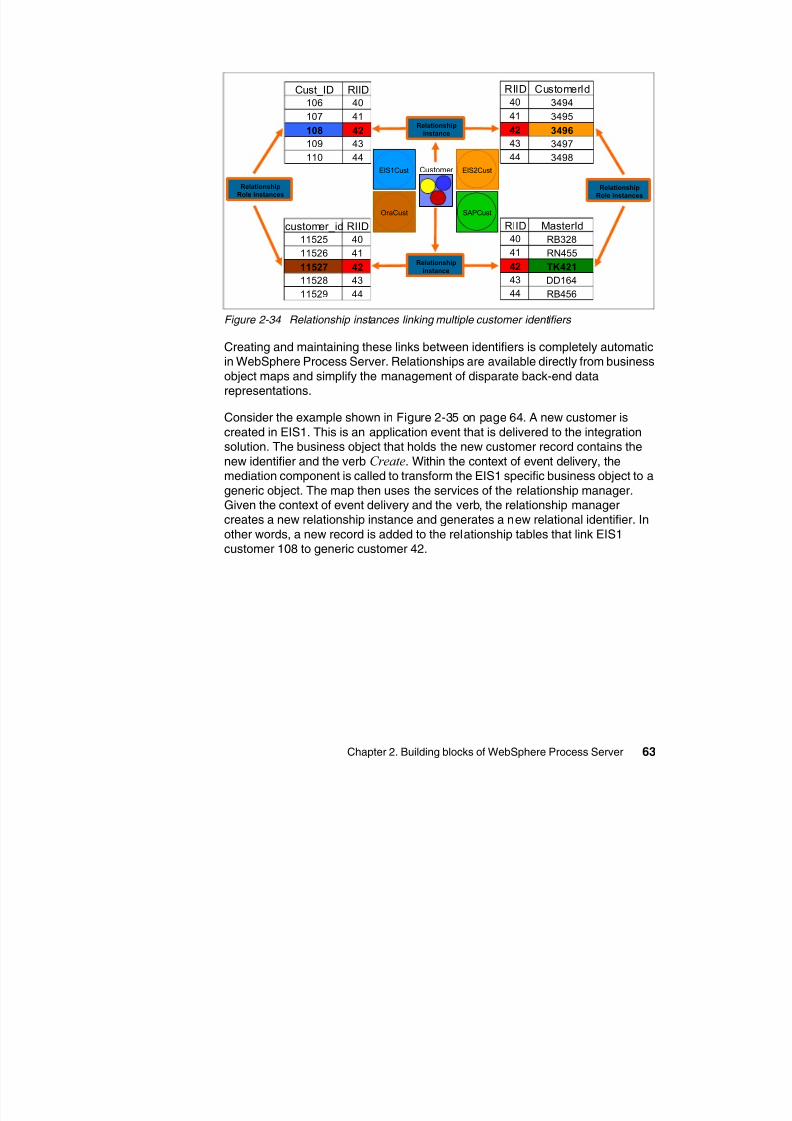
8/6/2019 WID RedBooks
http://slidepdf.com/reader/full/wid-redbooks 73/128
Chapter 2. Building blocks of WebSphere Process Server 63
Figure 2-34 Relationship instances linking multiple customer identifiers
Creating and maintaining these links between identifiers is completely automaticin WebSphere Process Server. Relationships are available directly from business
object maps and simplify the management of disparate back-end datarepresentations.
Consider the example shown in Figure 2-35 on page 64. A new customer iscreated in EIS1. This is an application event that is delivered to the integrationsolution. The business object that holds the new customer record contains the
new identifier and the verb Create. Within the context of event delivery, themediation component is called to transform the EIS1 specific business object to a
generic object. The map then uses the services of the relationship manager.Given the context of event delivery and the verb, the relationship managercreates a new relationship instance and generates a new relational identifier. In
other words, a new record is added to the relationship tables that link EIS1
customer 108 to generic customer 42.
Customer EIS2CustEIS1Cust
SAPCustOraCust
43 3497
44 3498
customer_id RIID11525 40
11526 41
11527 42
11528 4311529 44
RIID MasterId40 RB328
41 RN455
42 TK421
43 DD16444 RB456
109 43
110 44
Relationship
Role instancesRelationship
Role instances
Relationship
instance
Map
Relationship Relationship
Map
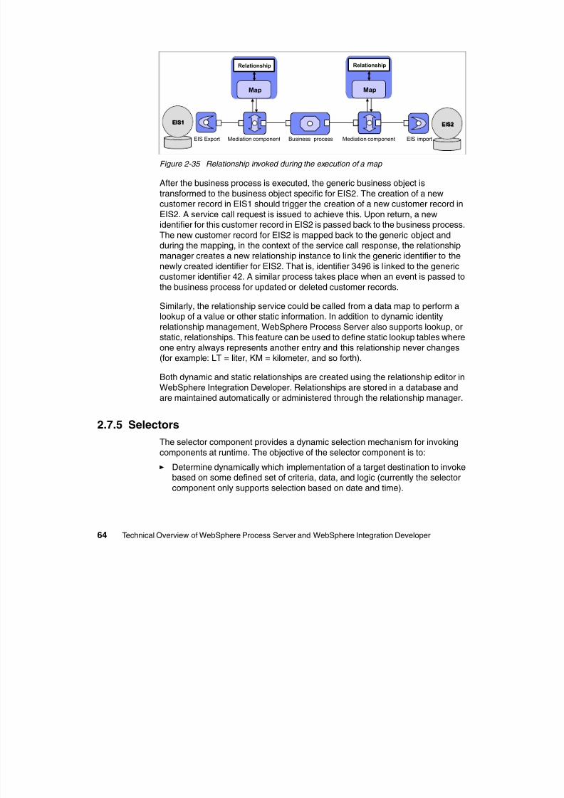
8/6/2019 WID RedBooks
http://slidepdf.com/reader/full/wid-redbooks 74/128
64 Technical Overview of WebSphere Process Server and WebSphere Integration Developer
Figure 2-35 Relationship invoked during the execution of a map
After the business process is executed, the generic business object is
transformed to the business object specific for EIS2. The creation of a new
customer record in EIS1 should trigger the creation of a new customer record inEIS2. A service call request is issued to achieve this. Upon return, a newidentifier for this customer record in EIS2 is passed back to the business process.
The new customer record for EIS2 is mapped back to the generic object andduring the mapping, in the context of the service call response, the relationshipmanager creates a new relationship instance to link the generic identifier to the
newly created identifier for EIS2. That is, identifier 3496 is l inked to the genericcustomer identifier 42. A similar process takes place when an event is passed to
the business process for updated or deleted customer records.
Similarly, the relationship service could be called from a data map to perform alookup of a value or other static information. In addition to dynamic identity
relationship management, WebSphere Process Server also supports lookup, orstatic, relationships. This feature can be used to define static lookup tables where
one entry always represents another entry and this relationship never changes(for example: LT = liter, KM = kilometer, and so forth).
Both dynamic and static relationships are created using the relationship editor in
WebSphere Integration Developer. Relationships are stored in a database andare maintained automatically or administered through the relationship manager.
2.7.5 Selectors
The selector component provides a dynamic selection mechanism for invoking
components at runtime. The objective of the selector component is to:
Determine dynamically which implementation of a target destination to invoke
based on some defined set of criteria, data, and logic (currently the selectorcomponent only supports selection based on date and time).
EIS1EIS1 EIS2EIS2
EIS importEIS Export Business processMediation component Mediation component
Decouple the client application from a specific target destinationimplementation allowing for dynamic selection and invocation of a target
destination.
Allow new implementations of target destinations to be added to the systemwithout requiring changes to the client application.
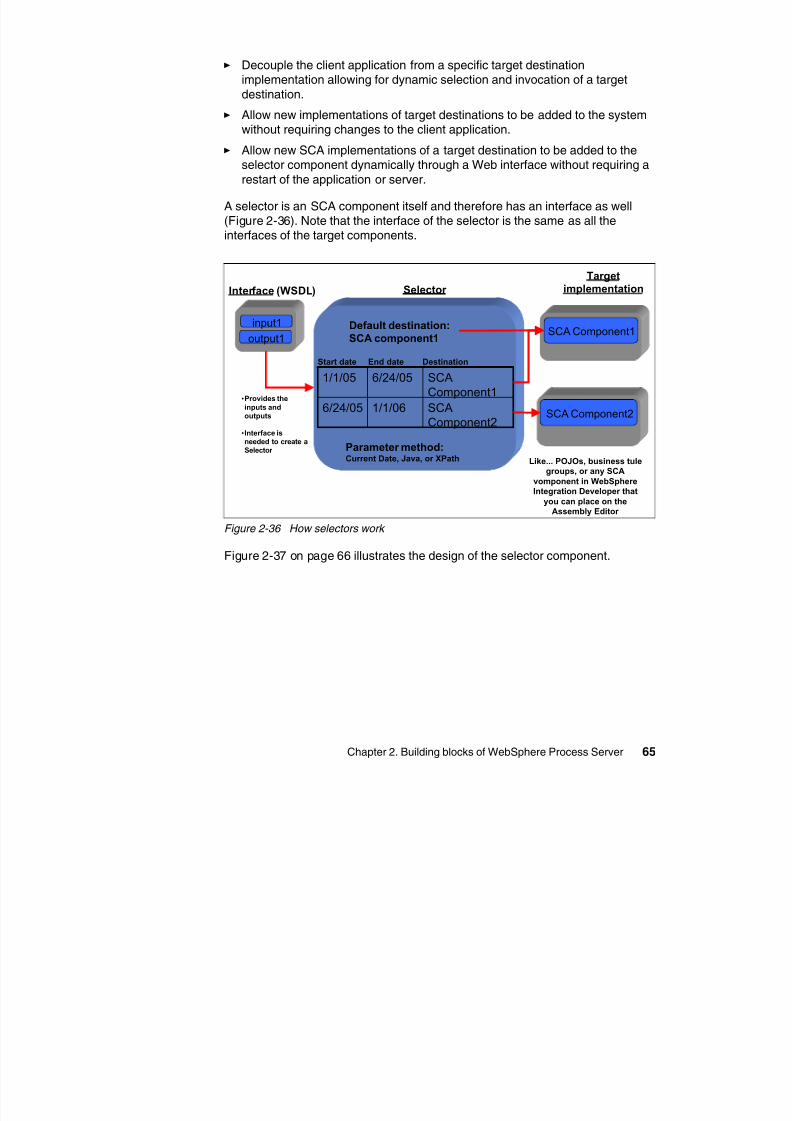
8/6/2019 WID RedBooks
http://slidepdf.com/reader/full/wid-redbooks 75/128
Chapter 2. Building blocks of WebSphere Process Server 65
Allow new SCA implementations of a target destination to be added to theselector component dynamically through a Web interface without requiring a
restart of the application or server.
A selector is an SCA component itself and therefore has an interface as well(Figure 2-36). Note that the interface of the selector is the same as all theinterfaces of the target components.
Figure 2-36 How selectors work
Figure 2-37 on page 66 illustrates the design of the selector component.
Interface (WSDL)
input1
output1
Selector
Target
implementation
Default destination:
SCA component1SCA Component1
SCA Component2SCAComponent2
1/1/066/24/05
SCAComponent1
6/24/051/1/05
Parameter method:Current Date, Java, or XPath
Start date End date Destination
Like... POJOs, business tule
groups, or any SCA
vomponent in WebSphere
Integration Developer that
you can place on the
Assembly Editor
•Provides the
inputs and
outputs
•Interface isneeded to create aSelector
Clients
JSPs
SCA
Selector
Destinations
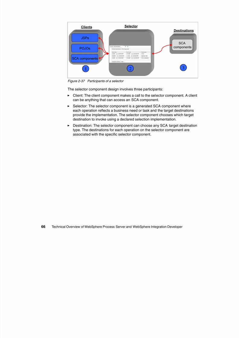
8/6/2019 WID RedBooks
http://slidepdf.com/reader/full/wid-redbooks 76/128
66 Technical Overview of WebSphere Process Server and WebSphere Integration Developer
Figure 2-37 Participants of a selector
The selector component design involves three participants:
Client: The client component makes a call to the selector component. A clientcan be anything that can access an SCA component.
Selector: The selector component is a generated SCA component where
each operation reflects a business need or task and the target destinationsprovide the implementation. The selector component chooses which target
destination to invoke using a declared selection implementation.
Destination: The selector component can choose any SCA target destinationtype. The destinations for each operation on the selector component are
associated with the specific selector component.
POJOs
SCA components
components
1 2 3
3
8/6/2019 WID RedBooks
http://slidepdf.com/reader/full/wid-redbooks 77/128
© Copyright IBM Corp. 2005. All rights reserved. 67
Chapter 3. Developing a simplesolution
In Chapter 2, “Building blocks of WebSphere Process Server” on page 23, we
introduced some of the major concepts and terminology that you need to befamiliar with when starting to build a process integration solution. In this chapter,
we go a little fur ther and build a simple example to reinforce these concepts.
As with all good IT-related beginnings, we start with a classic Hello World
application. In our example, we show how to use WebSphere IntegrationDeveloper to create a very simple application that is built upon SCA.
3.1 Getting started
The Hello World application in this example consists of a single service
component that is associated with a simple WSDL interface definition. Thisdefinition includes a sendMessage operation. The service component in the
application uses a Java implementation (POJO) to provide the sendMessage
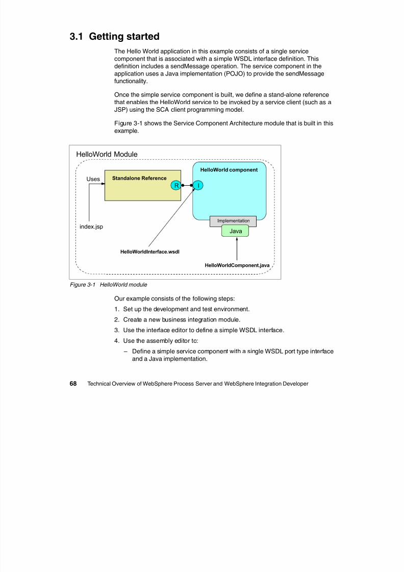
8/6/2019 WID RedBooks
http://slidepdf.com/reader/full/wid-redbooks 78/128
68 Technical Overview of WebSphere Process Server and WebSphere Integration Developer
functionality.
Once the simple service component is built, we define a stand-alone reference
that enables the HelloWorld service to be invoked by a service client (such as aJSP) using the SCA client programming model.
Figure 3-1 shows the Service Component Architecture module that is built in this
example.
Figure 3-1 HelloWorld module
Our example consists of the following steps:
1. Set up the development and test environment.
2. Create a new business integration module.
3. Use the interface editor to define a simple WSDL interface.
4. Use the assembly editor to:
– Define a simple service component with a single WSDL port type interface
and a Java implementation.
HelloWorld component
Standalone Reference
Implementation
Java
IRUses
index.jsp
HelloWorldInterface.wsdl
HelloWorldComponent.java
HelloWorld Module
– Define a stand-alone reference to the simple service component.
– Assemble a service module.
5. Use the SCA client programming model to invoke the service component fromwithin a service client.
6. Test the service component invocation from:
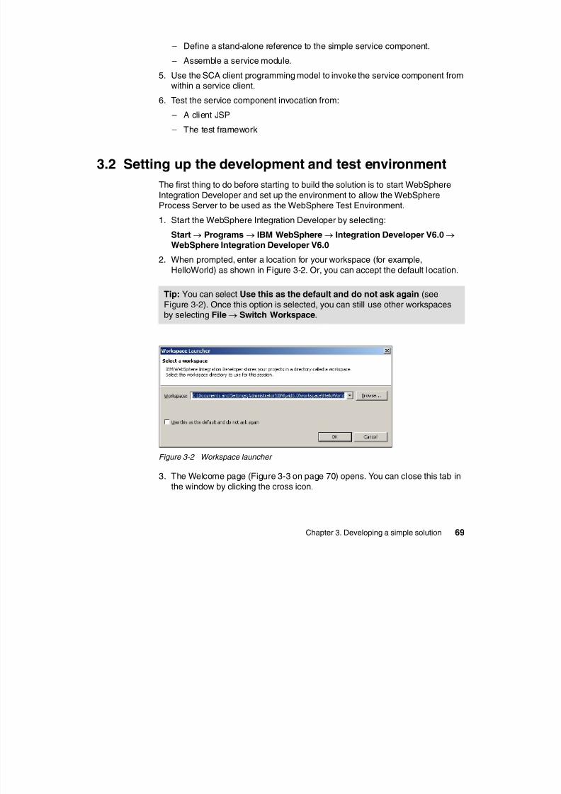
8/6/2019 WID RedBooks
http://slidepdf.com/reader/full/wid-redbooks 79/128
Chapter 3. Developing a simple solution 69
– A client JSP
– The test framework
3.2 Setting up the development and test environment
The first thing to do before starting to build the solution is to start WebSphere
Integration Developer and set up the environment to allow the WebSphere
Process Server to be used as the WebSphere Test Environment.
1. Start the WebSphere Integration Developer by selecting:
Start→ Programs→ IBM WebSphere→ Integration Developer V6.0→ WebSphere Integration Developer V6.0
2. When prompted, enter a location for your workspace (for example,
HelloWorld) as shown in Figure 3-2. Or, you can accept the default location.
Figure 3-2 Workspace launcher
3. The Welcome page (Figure 3-3 on page 70) opens. You can close this tab inthe window by clicking the cross icon.
Tip: You can select Use this as the default and do not ask again (seeFigure 3-2). Once this option is selected, you can still use other workspacesby selecting File→ Switch Workspace.
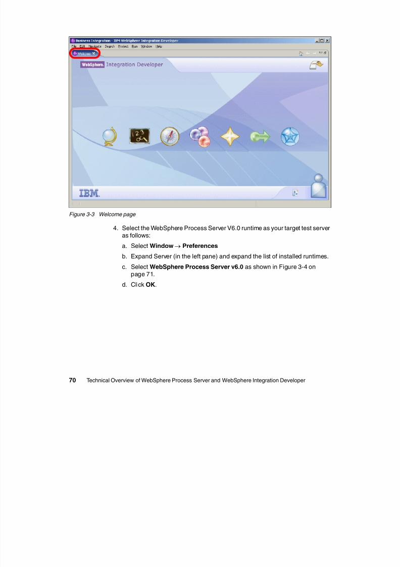
8/6/2019 WID RedBooks
http://slidepdf.com/reader/full/wid-redbooks 80/128
70 Technical Overview of WebSphere Process Server and WebSphere Integration Developer
Figure 3-3 Welcome page
4. Select the WebSphere Process Server V6.0 runtime as your target test serveras follows:
a. Select Window→ Preferences
b. Expand Server (in the left pane) and expand the list of installed runtimes.
c. Select WebSphere Process Server v6.0 as shown in Figure 3-4 on
page 71.d. Click OK.
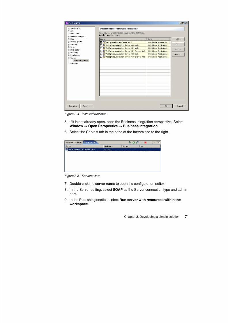
8/6/2019 WID RedBooks
http://slidepdf.com/reader/full/wid-redbooks 81/128
Chapter 3. Developing a simple solution 71
Figure 3-4 Installed runtimes
5. If it is not already open, open the Business Integration perspective. SelectWindow→ Open Perspective→ Business Integration.
6. Select the Servers tab in the pane at the bottom and to the right.
Figure 3-5 Servers view
7. Double-click the server name to open the configuration editor.
8. In the Server setting, select SOAP as the Server connection type and admin
port.9. In the Publishing section, select Run server with resources within the
workspace.
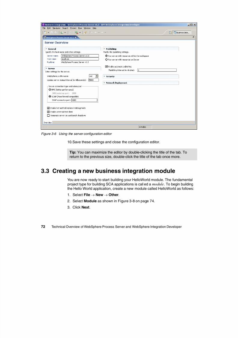
8/6/2019 WID RedBooks
http://slidepdf.com/reader/full/wid-redbooks 82/128
72 Technical Overview of WebSphere Process Server and WebSphere Integration Developer
Figure 3-6 Using the server configuration editor
10.Save these settings and close the configuration editor.
3.3 Creating a new business integration module
You are now ready to start building your HelloWorld module. The fundamental
project type for building SCA applications is called a module. To begin buildingthe Hello World application, create a new module called HelloWorld as follows:
1. Select File→ New→ Other.
2. Select Module as shown in Figure 3-8 on page 74.
3. Click Next.
Tip: You can maximize the editor by double-clicking the title of the tab. Toreturn to the previous size, double-click the title of the tab once more.
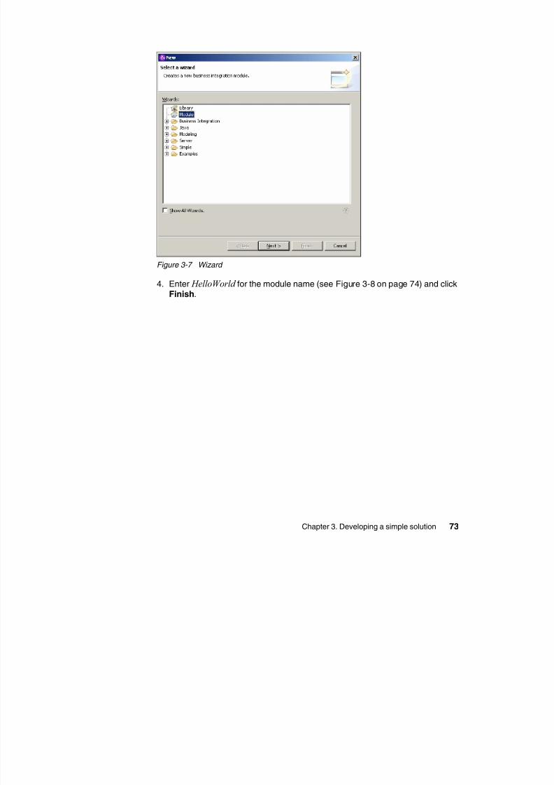
8/6/2019 WID RedBooks
http://slidepdf.com/reader/full/wid-redbooks 83/128
Chapter 3. Developing a simple solution 73
Figure 3-7 Wizard
4. Enter HelloWorld for the module name (see Figure 3-8 on page 74) and click
Finish.
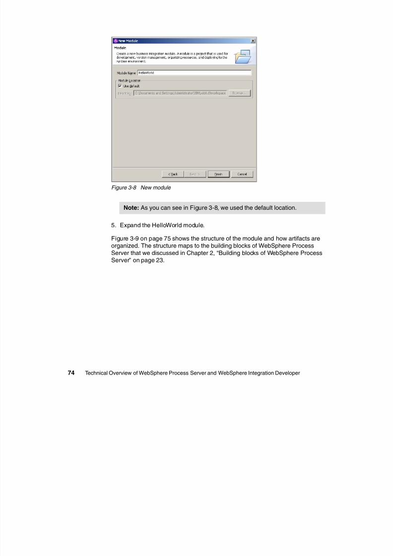
8/6/2019 WID RedBooks
http://slidepdf.com/reader/full/wid-redbooks 84/128
74 Technical Overview of WebSphere Process Server and WebSphere Integration Developer
Figure 3-8 New module
5. Expand the HelloWorld module.
Figure 3-9 on page 75 shows the structure of the module and how artifacts areorganized. The structure maps to the building blocks of WebSphere Process
Server that we discussed in Chapter 2, “Building blocks of WebSphere ProcessServer” on page 23.
Note: As you can see in Figure 3-8, we used the default location.
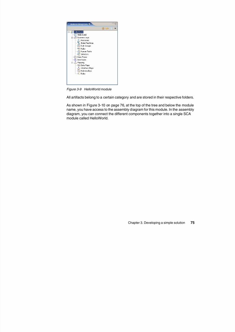
8/6/2019 WID RedBooks
http://slidepdf.com/reader/full/wid-redbooks 85/128
Chapter 3. Developing a simple solution 75
Figure 3-9 HelloWorld module
All artifacts belong to a certain category and are stored in their respective folders.
As shown in Figure 3-10 on page 76, at the top of the tree and below the modulename, you have access to the assembly diagram for this module. In the assembly
diagram, you can connect the different components together into a single SCAmodule called HelloWorld.
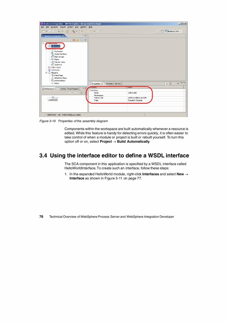
8/6/2019 WID RedBooks
http://slidepdf.com/reader/full/wid-redbooks 86/128
76 Technical Overview of WebSphere Process Server and WebSphere Integration Developer
Figure 3-10 Properties of the assembly diagram
Components within the workspace are built automatically whenever a resource is
edited. While this feature is handy for detecting errors quickly, it is often easier totake control of when a module or project is built or rebuilt yourself. To turn this
option off or on, select Project→ Build Automatically.
3.4 Using the interface editor to define a WSDL interfaceThe SCA component in this application is specified by a WSDL interface called
HelloWorldInterface. To create such an interface, follow these steps:
1. In the expanded HelloWorld module, right-click Interfaces and select New→ Interface as shown in Figure 3-11 on page 77.
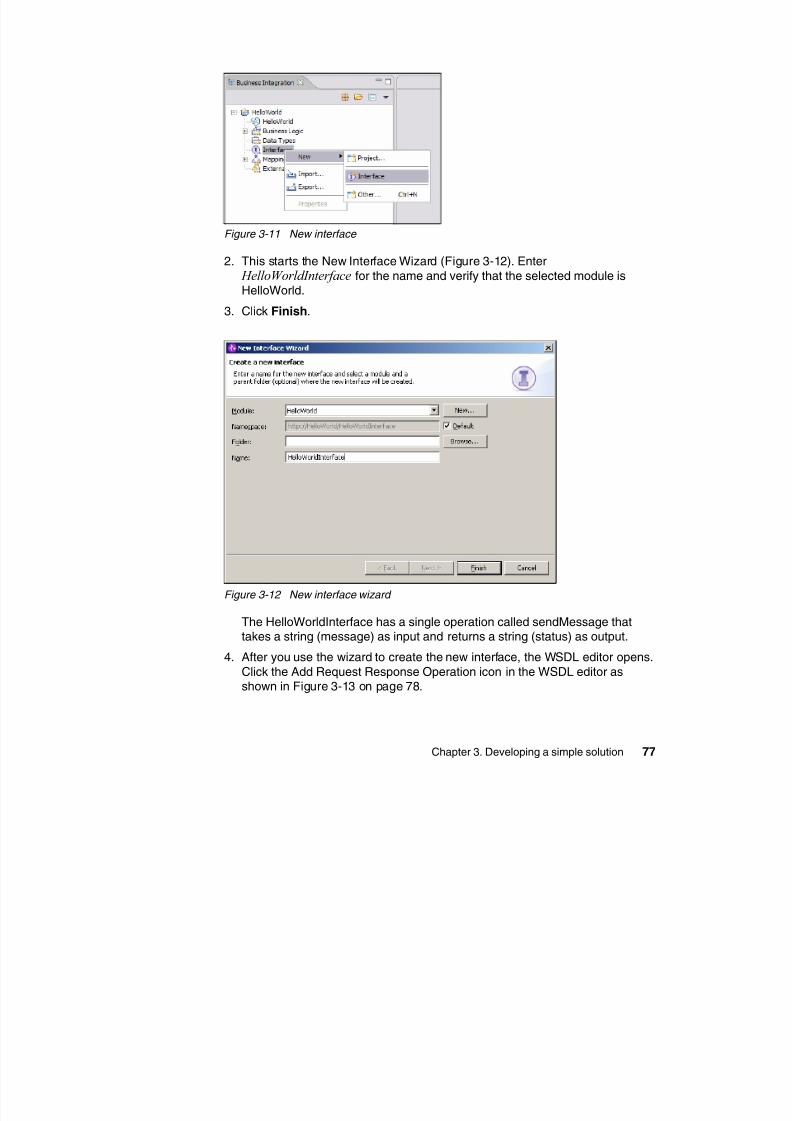
8/6/2019 WID RedBooks
http://slidepdf.com/reader/full/wid-redbooks 87/128
Chapter 3. Developing a simple solution 77
Figure 3-11 New interface
2. This starts the New Interface Wizard (Figure 3-12). Enter HelloWorldInterface for the name and verify that the selected module is
HelloWorld.
3. Click Finish.
Figure 3-12 New interface wizard
The HelloWorldInterface has a single operation called sendMessage thattakes a string (message) as input and returns a string (status) as output.
4. After you use the wizard to create the new interface, the WSDL editor opens.
Click the Add Request Response Operation icon in the WSDL editor asshown in Figure 3-13 on page 78.
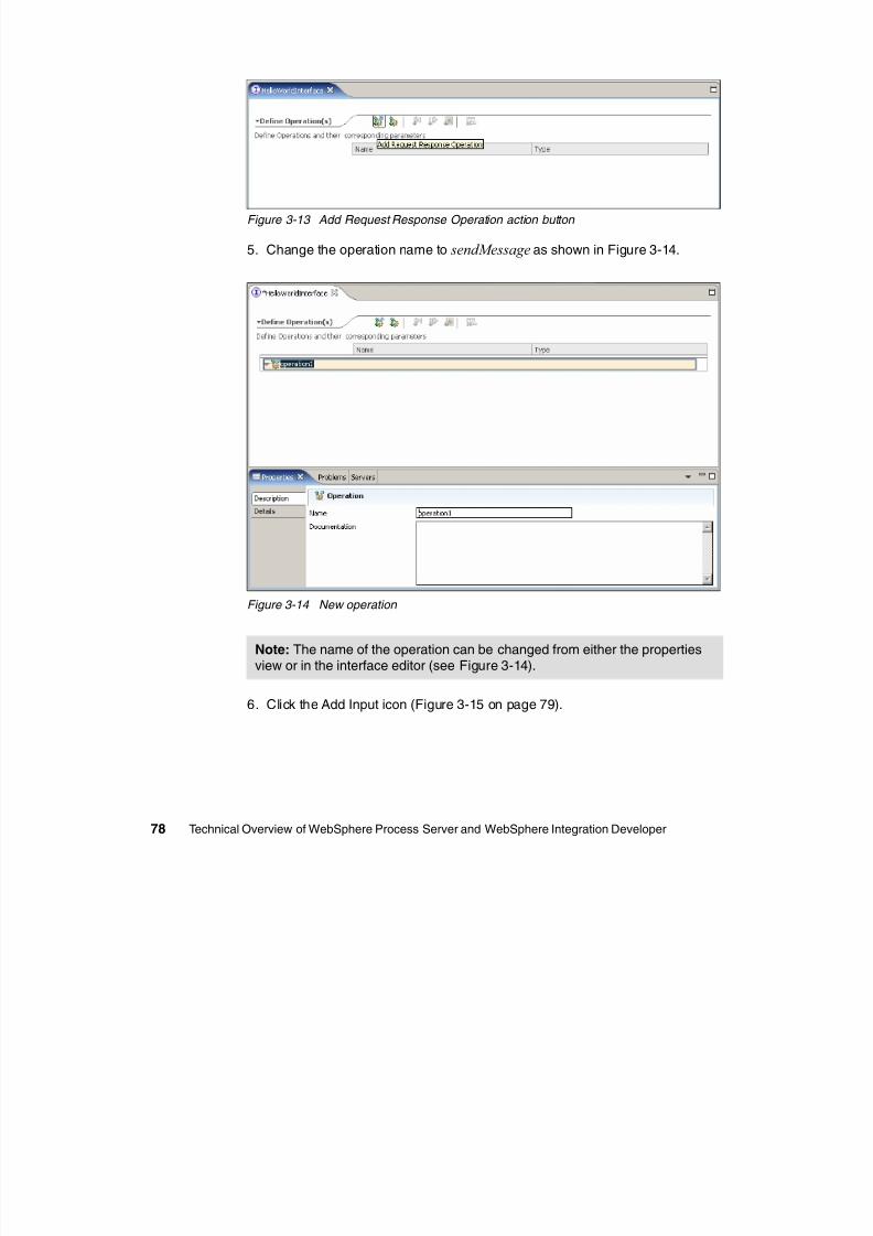
8/6/2019 WID RedBooks
http://slidepdf.com/reader/full/wid-redbooks 88/128
78 Technical Overview of WebSphere Process Server and WebSphere Integration Developer
Figure 3-13 Add Request Response Operation action button
5. Change the operation name to sendMessage as shown in Figure 3-14.
Figure 3-14 New operation
6. Click the Add Input icon (Figure 3-15 on page 79).
Note: The name of the operation can be changed from either the propertiesview or in the interface editor (see Figure 3-14).
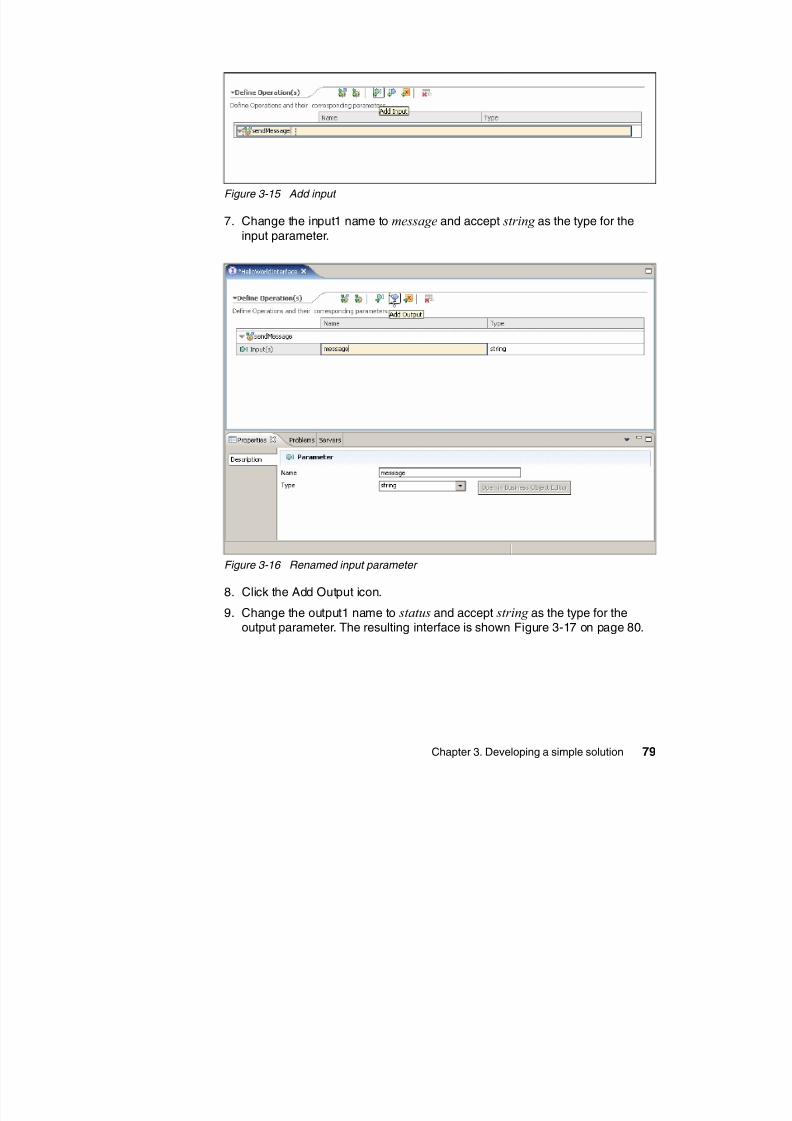
8/6/2019 WID RedBooks
http://slidepdf.com/reader/full/wid-redbooks 89/128
Chapter 3. Developing a simple solution 79
Figure 3-15 Add input
7. Change the input1 name to message and accept string as the type for the
input parameter.
Figure 3-16 Renamed input parameter
8. Click the Add Output icon.
9. Change the output1 name to status and accept string as the type for theoutput parameter. The resulting interface is shown Figure 3-17 on page 80.
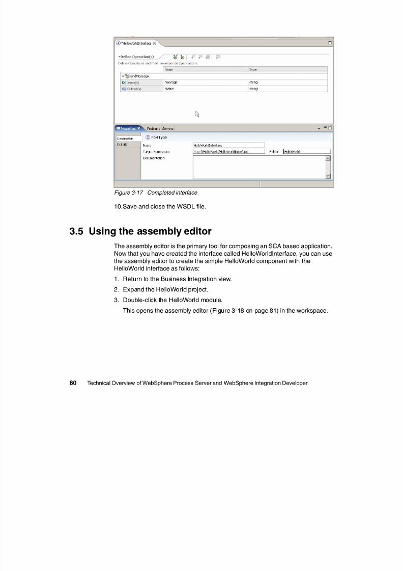
8/6/2019 WID RedBooks
http://slidepdf.com/reader/full/wid-redbooks 90/128
80 Technical Overview of WebSphere Process Server and WebSphere Integration Developer
Figure 3-17 Completed interface
10.Save and close the WSDL file.
3.5 Using the assembly editor
The assembly editor is the primary tool for composing an SCA based application.
Now that you have created the interface called HelloWorldInterface, you can usethe assembly editor to create the simple HelloWorld component with the
HelloWorld interface as follows:
1. Return to the Business Integration view.2. Expand the HelloWorld project.
3. Double-click the HelloWorld module.
This opens the assembly editor (Figure 3-18 on page 81) in the workspace.
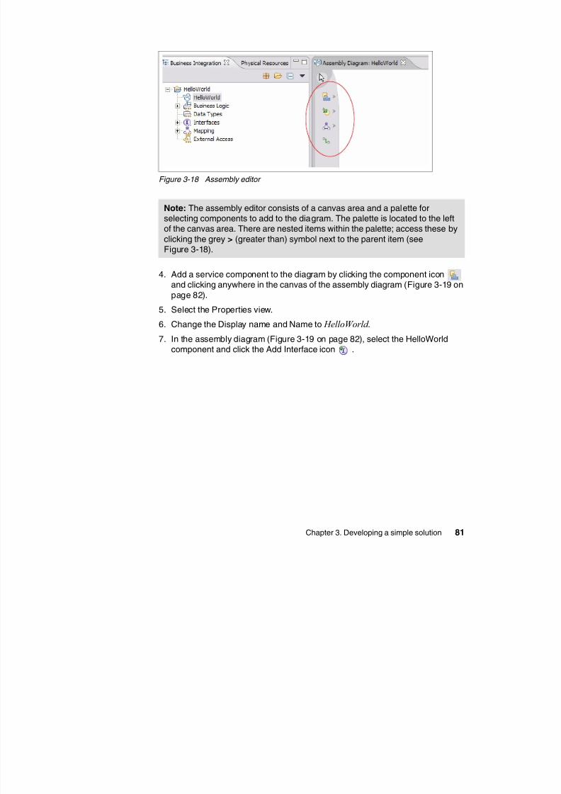
8/6/2019 WID RedBooks
http://slidepdf.com/reader/full/wid-redbooks 91/128
Chapter 3. Developing a simple solution 81
Figure 3-18 Assembly editor
4. Add a service component to the diagram by clicking the component iconand clicking anywhere in the canvas of the assembly diagram (Figure 3-19 on
page 82).5. Select the Properties view.
6. Change the Display name and Name to HelloWorld .
7. In the assembly diagram (Figure 3-19 on page 82), select the HelloWorldcomponent and click the Add Interface icon .
Note: The assembly editor consists of a canvas area and a palette forselecting components to add to the diagram. The palette is located to the leftof the canvas area. There are nested items within the palette; access these by
clicking the grey > (greater than) symbol next to the parent item (seeFigure 3-18).
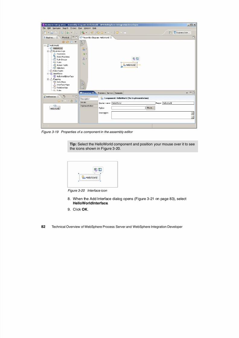
8/6/2019 WID RedBooks
http://slidepdf.com/reader/full/wid-redbooks 92/128
82 Technical Overview of WebSphere Process Server and WebSphere Integration Developer
Figure 3-19 Properties of a component in the assembly editor
Figure 3-20 Interface icon
8. When the Add Interface dialog opens (Figure 3-21 on page 83), selectHelloWorldInterface.
9. Click OK.
Tip: Select the HelloWorld component and position your mouse over it to seethe icons shown in Figure 3-20.
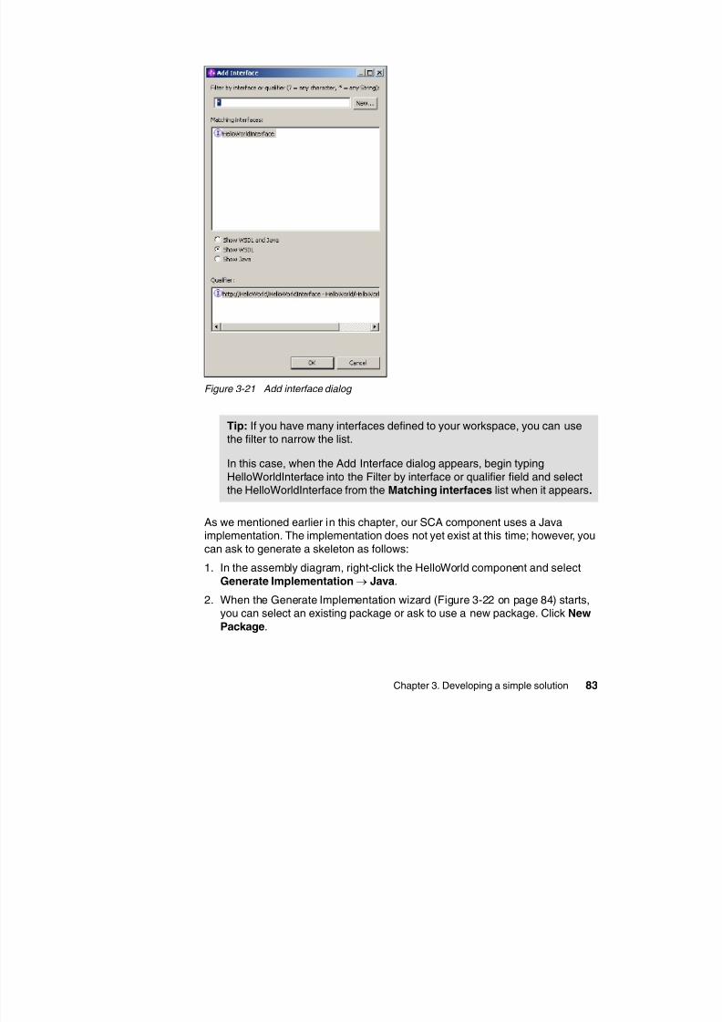
8/6/2019 WID RedBooks
http://slidepdf.com/reader/full/wid-redbooks 93/128
Chapter 3. Developing a simple solution 83
Figure 3-21 Add interface dialog
As we mentioned earlier in this chapter, our SCA component uses a Javaimplementation. The implementation does not yet exist at this time; however, you
can ask to generate a skeleton as follows:
1. In the assembly diagram, right-click the HelloWorld component and select
Generate Implementation→ Java.
2. When the Generate Implementation wizard (Figure 3-22 on page 84) starts,you can select an existing package or ask to use a new package. Click New
Package.
Tip: If you have many interfaces defined to your workspace, you can usethe filter to narrow the list.
In this case, when the Add Interface dialog appears, begin typing
HelloWorldInterface into the Filter by interface or qualifier field and selectthe HelloWorldInterface from the Matching interfaces list when it appears.
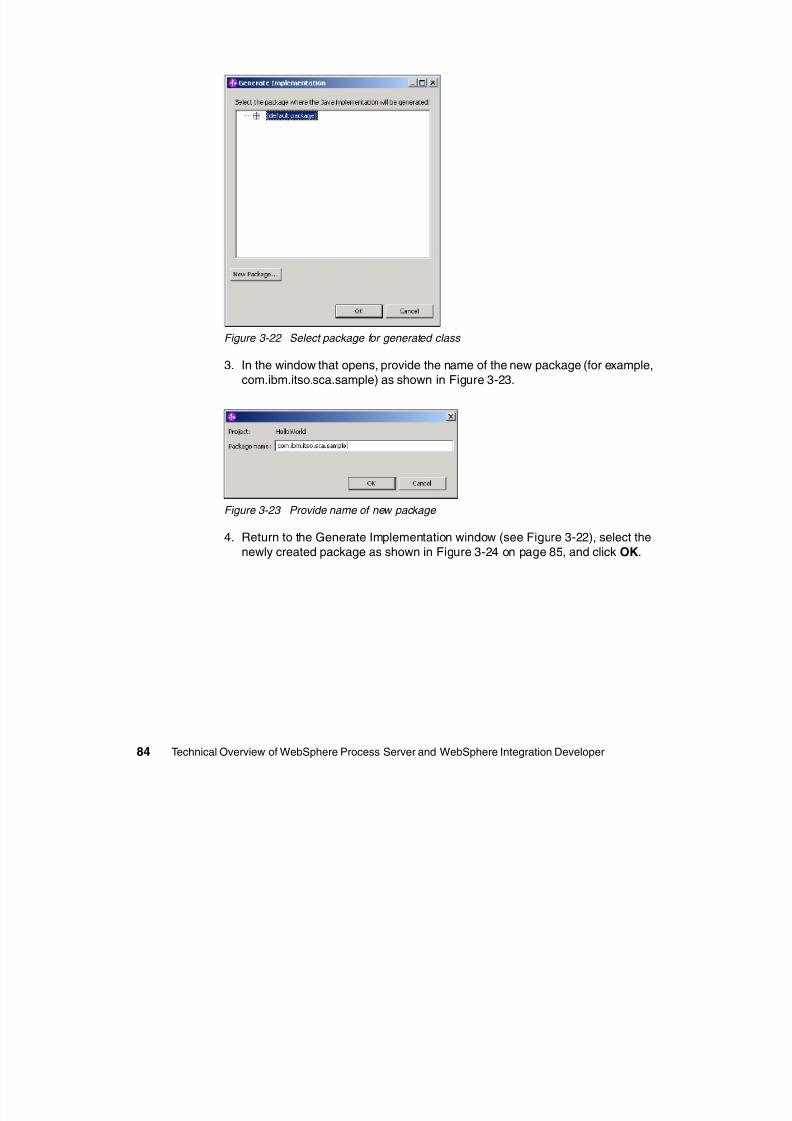
8/6/2019 WID RedBooks
http://slidepdf.com/reader/full/wid-redbooks 94/128
84 Technical Overview of WebSphere Process Server and WebSphere Integration Developer
Figure 3-22 Select package for generated class
3. In the window that opens, provide the name of the new package (for example,
com.ibm.itso.sca.sample) as shown in Figure 3-23.
Figure 3-23 Provide name of new package
4. Return to the Generate Implementation window (see Figure 3-22), select the
newly created package as shown in Figure 3-24 on page 85, and click OK.
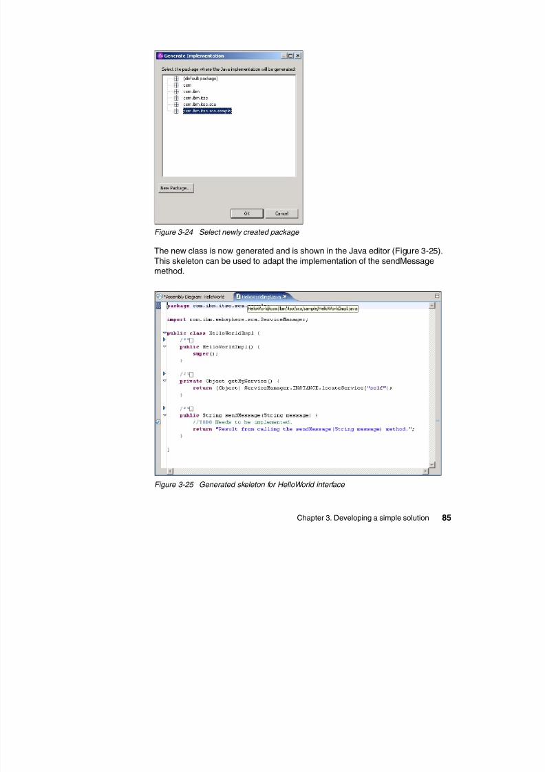
8/6/2019 WID RedBooks
http://slidepdf.com/reader/full/wid-redbooks 95/128
Chapter 3. Developing a simple solution 85
Figure 3-24 Select newly created package
The new class is now generated and is shown in the Java editor (Figure 3-25).
This skeleton can be used to adapt the implementation of the sendMessagemethod.
Figure 3-25 Generated skeleton for HelloWorld interface
If you wish, you can alter the implementation of sendMessage to return a stringthat includes the original message. See Example 3-1.
Example 3-1 New implementation of sendMessage method
public String sendMessage(String message) {System.out.println("MESSAGE>> " + message);return "Did you say? " + message;
}
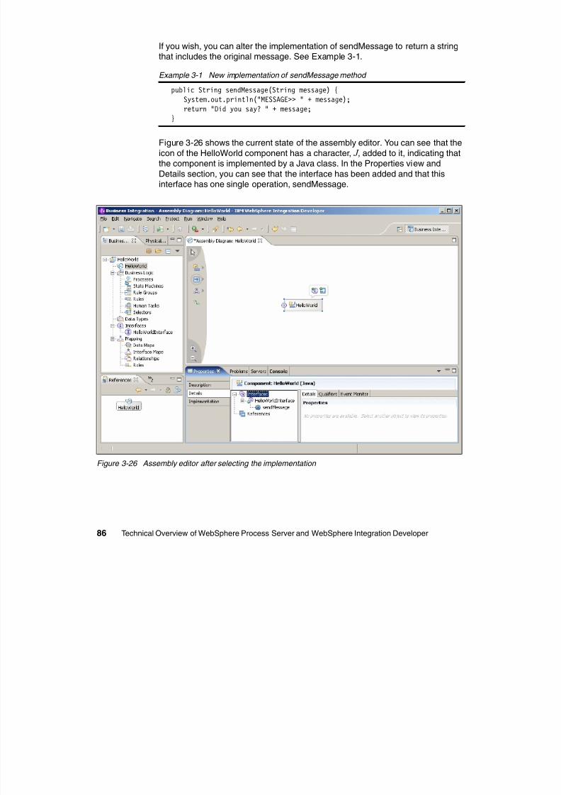
8/6/2019 WID RedBooks
http://slidepdf.com/reader/full/wid-redbooks 96/128
86 Technical Overview of WebSphere Process Server and WebSphere Integration Developer
Figure 3-26 shows the current state of the assembly editor. You can see that the
icon of the HelloWorld component has a character, J , added to it, indicating thatthe component is implemented by a Java class. In the Properties view and
Details section, you can see that the interface has been added and that thisinterface has one single operation, sendMessage.
Figure 3-26 Assembly editor after selecting the implementation
The SCA component is called by a client implemented as a JSP. To allow this,you need to add a stand-alone reference to the component as follows.
1. Using the palette, select the stand-alone reference icon and add it to the
canvas.
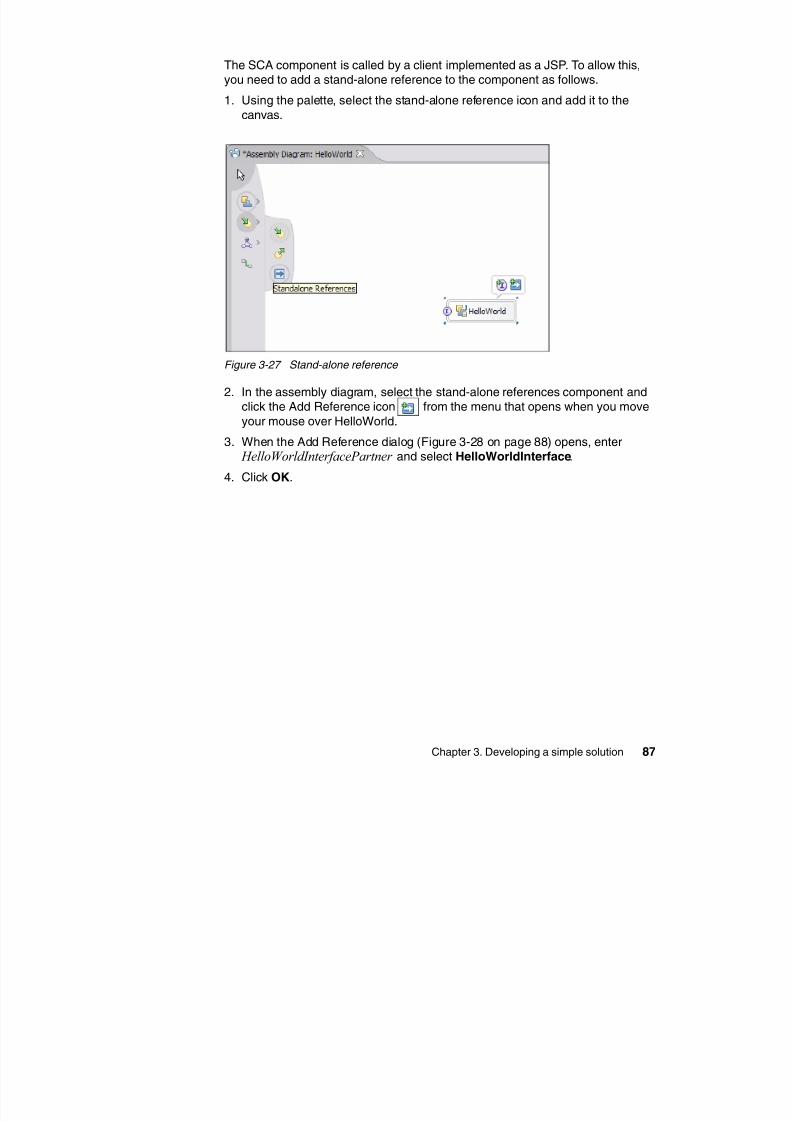
8/6/2019 WID RedBooks
http://slidepdf.com/reader/full/wid-redbooks 97/128
Chapter 3. Developing a simple solution 87
Figure 3-27 Stand-alone reference
2. In the assembly diagram, select the stand-alone references component andclick the Add Reference icon from the menu that opens when you move
your mouse over HelloWorld.3. When the Add Reference dialog (Figure 3-28 on page 88) opens, enter
HelloWorldInterfacePartner and select HelloWorldInterface.
4. Click OK.
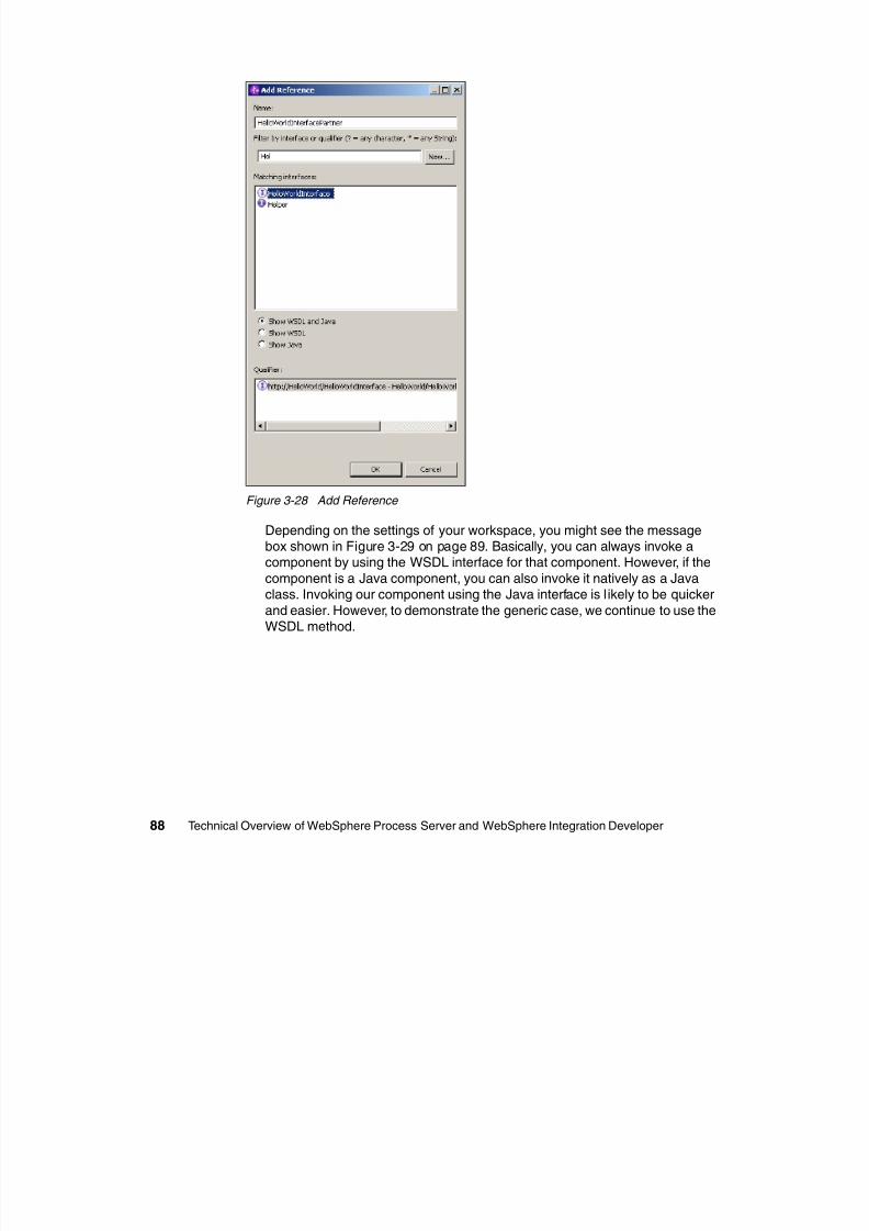
8/6/2019 WID RedBooks
http://slidepdf.com/reader/full/wid-redbooks 98/128
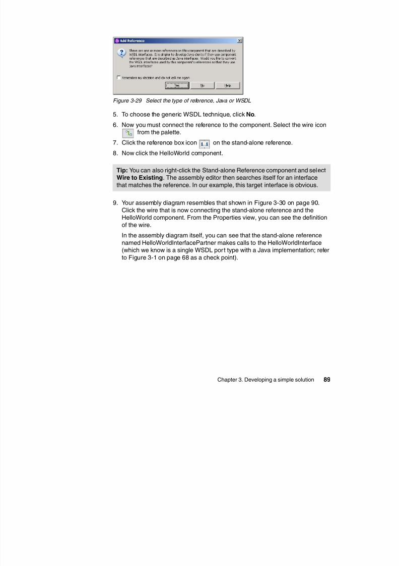
8/6/2019 WID RedBooks
http://slidepdf.com/reader/full/wid-redbooks 99/128
Chapter 3. Developing a simple solution 89
Figure 3-29 Select the type of reference, Java or WSDL
5. To choose the generic WSDL technique, click No.
6. Now you must connect the reference to the component. Select the wire iconfrom the palette.
7. Click the reference box icon on the stand-alone reference.
8. Now click the HelloWorld component.
9. Your assembly diagram resembles that shown in Figure 3-30 on page 90.
Click the wire that is now connecting the stand-alone reference and theHelloWorld component. From the Properties view, you can see the definition
of the wire.
In the assembly diagram itself, you can see that the stand-alone reference
named HelloWorldInterfacePartner makes calls to the HelloWorldInterface(which we know is a single WSDL por t type with a Java implementation; refer
to Figure 3-1 on page 68 as a check point).
Tip: You can also right-click the Stand-alone Reference component and selectWire to Existing. The assembly editor then searches itself for an interface
that matches the reference. In our example, this target interface is obvious.
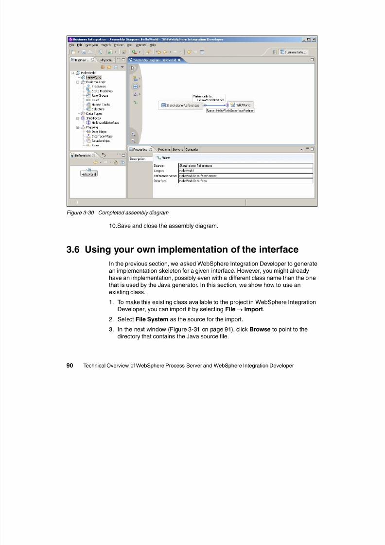
8/6/2019 WID RedBooks
http://slidepdf.com/reader/full/wid-redbooks 100/128
90 Technical Overview of WebSphere Process Server and WebSphere Integration Developer
Figure 3-30 Completed assembly diagram
10.Save and close the assembly diagram.
3.6 Using your own implementation of the interface
In the previous section, we asked WebSphere Integration Developer to generate
an implementation skeleton for a given interface. However, you might alreadyhave an implementation, possibly even with a different class name than the onethat is used by the Java generator. In this section, we show how to use an
existing class.
1. To make this existing class available to the project in WebSphere IntegrationDeveloper, you can import it by selecting File→ Import.
2. Select File System as the source for the import.
3. In the next window (Figure 3-31 on page 91), click Browse to point to thedirectory that contains the Java source file.
4. After the directory has been identified, select the file that you want to import(HelloWorldComponent.java in our example in Figure 3-31).
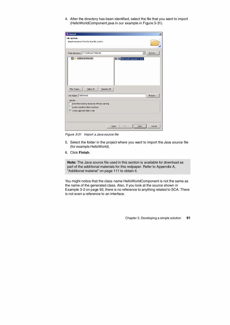
8/6/2019 WID RedBooks
http://slidepdf.com/reader/full/wid-redbooks 101/128
Chapter 3. Developing a simple solution 91
Figure 3-31 Import a Java source file
5. Select the folder in the project where you want to import the Java source file
(for example HelloWorld).
6. Click Finish.
You might notice that the class name HelloWorldComponent is not the same as
the name of the generated class. Also, if you look at the source shown inExample 3-2 on page 92, there is no reference to anything related to SCA. There
is not even a reference to an interface.
Note: The Java source file used in this section is available for download aspart of the additional materials for this redpaper. Refer to Appendix A,“Additional material” on page 111 to obtain it.
Example 3-2 Implementation of the class HelloWorldComponent
package com.ibm.itso.sca.sample;
public class HelloWorldComponent {
public String sendMessage(String message) {System.out.println("MESSAGE>> " + message);
return "Did you say? " + message;}
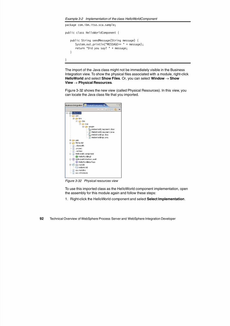
8/6/2019 WID RedBooks
http://slidepdf.com/reader/full/wid-redbooks 102/128
92 Technical Overview of WebSphere Process Server and WebSphere Integration Developer
}
The import of the Java class might not be immediately visible in the BusinessIntegration view. To show the physical files associated with a module, right-click
HelloWorld and select Show Files. Or, you can select Window→ ShowView→ Physical Resources.
Figure 3-32 shows the new view (called Physical Resources). In this view, youcan locate the Java class file that you imported.
Figure 3-32 Physical resources view
To use this imported class as the HelloWorld component implementation, openthe assembly for this module again and follow these steps:
1. Right-click the HelloWorld component and select Select Implementation.
2. In the Pick Implementation window (Figure 3-33), alter the selection filter untilthe Matching types list shows the HelloWorldComponent class.
3. Select the class and click OK.
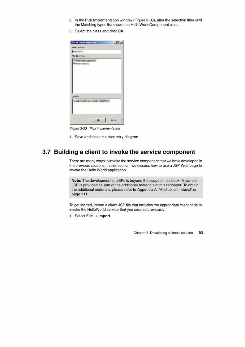
8/6/2019 WID RedBooks
http://slidepdf.com/reader/full/wid-redbooks 103/128
Chapter 3. Developing a simple solution 93
Figure 3-33 Pick implementation
4. Save and close the assembly diagram.
3.7 Building a client to invoke the service component
There are many ways to invoke the service component that we have developed in
the previous sections. In this section, we discuss how to use a JSP Web page toinvoke the Hello World application.
To get started, import a client JSP file that includes the appropriate client code to
invoke the HelloWorld service that you created previously:
1. Select File→ Import.
Note: The development of JSPs is beyond the scope of this book. A sampleJSP is provided as part of the additional materials of this redpaper. To obtainthe additional materials, please refer to Appendix A, “Additional material” on
page 111.
2. Select File System and click Next.
3. Browse to the folder that contains the unzipped additional material.
4. Select the index.jsp file (Figure 3-34).
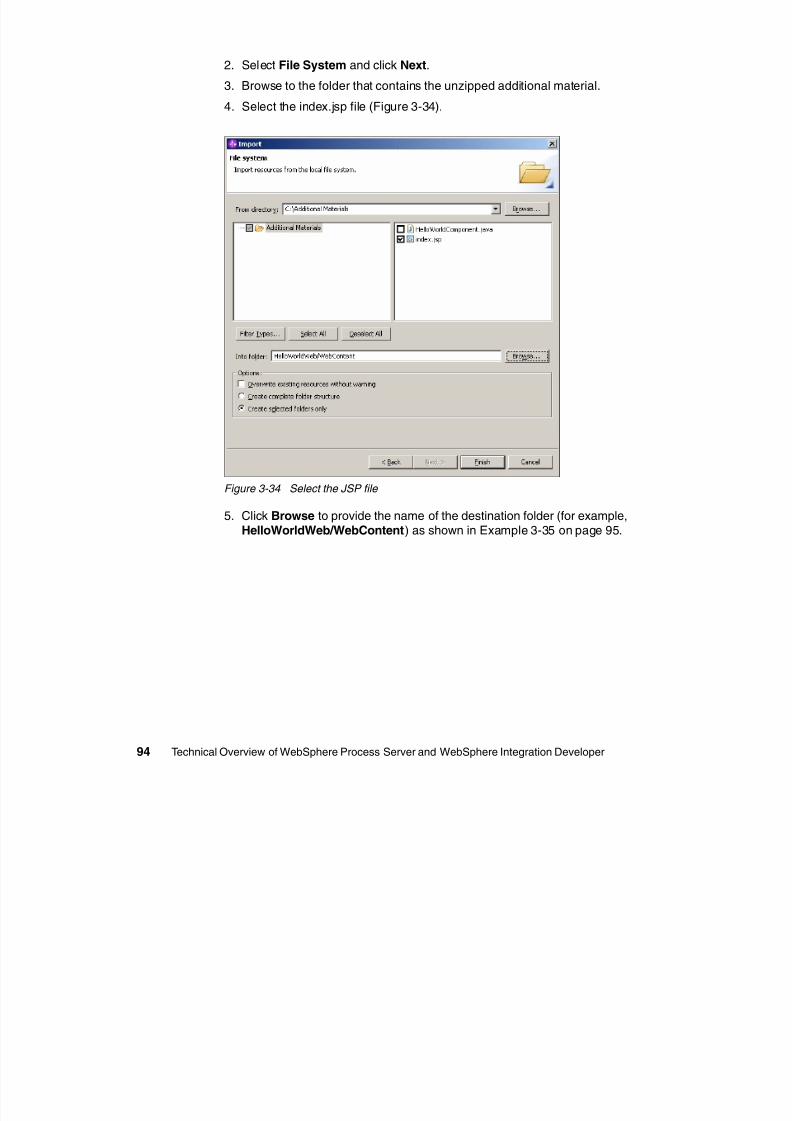
8/6/2019 WID RedBooks
http://slidepdf.com/reader/full/wid-redbooks 104/128
94 Technical Overview of WebSphere Process Server and WebSphere Integration Developer
Figure 3-34 Select the JSP file
5. Click Browse to provide the name of the destination folder (for example,HelloWorldWeb/WebContent) as shown in Example 3-35 on page 95.
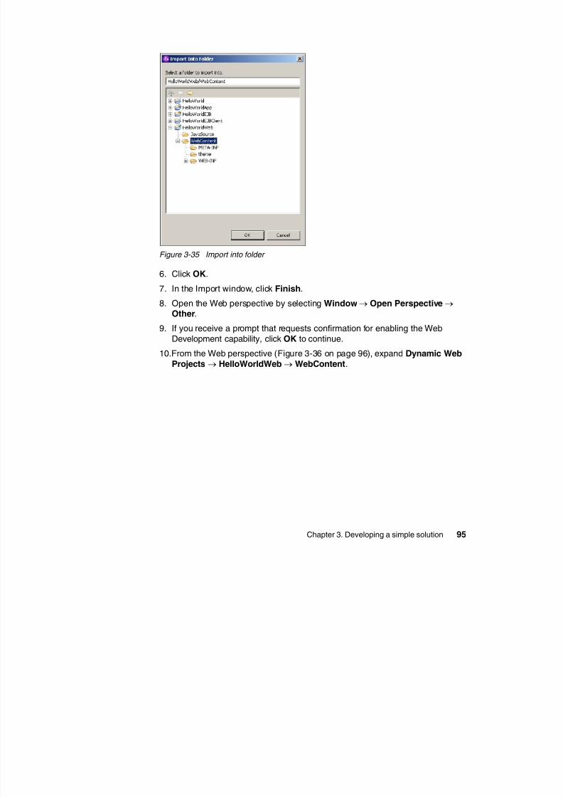
8/6/2019 WID RedBooks
http://slidepdf.com/reader/full/wid-redbooks 105/128
Chapter 3. Developing a simple solution 95
Figure 3-35 Import into folder
6. Click OK.
7. In the Import window, click Finish.
8. Open the Web perspective by selecting Window→ Open Perspective→ Other.
9. If you receive a prompt that requests confirmation for enabling the Web
Development capability, click OK to continue.
10.From the Web perspective (Figure 3-36 on page 96), expand Dynamic Web
Projects→ HelloWorldWeb→WebContent.
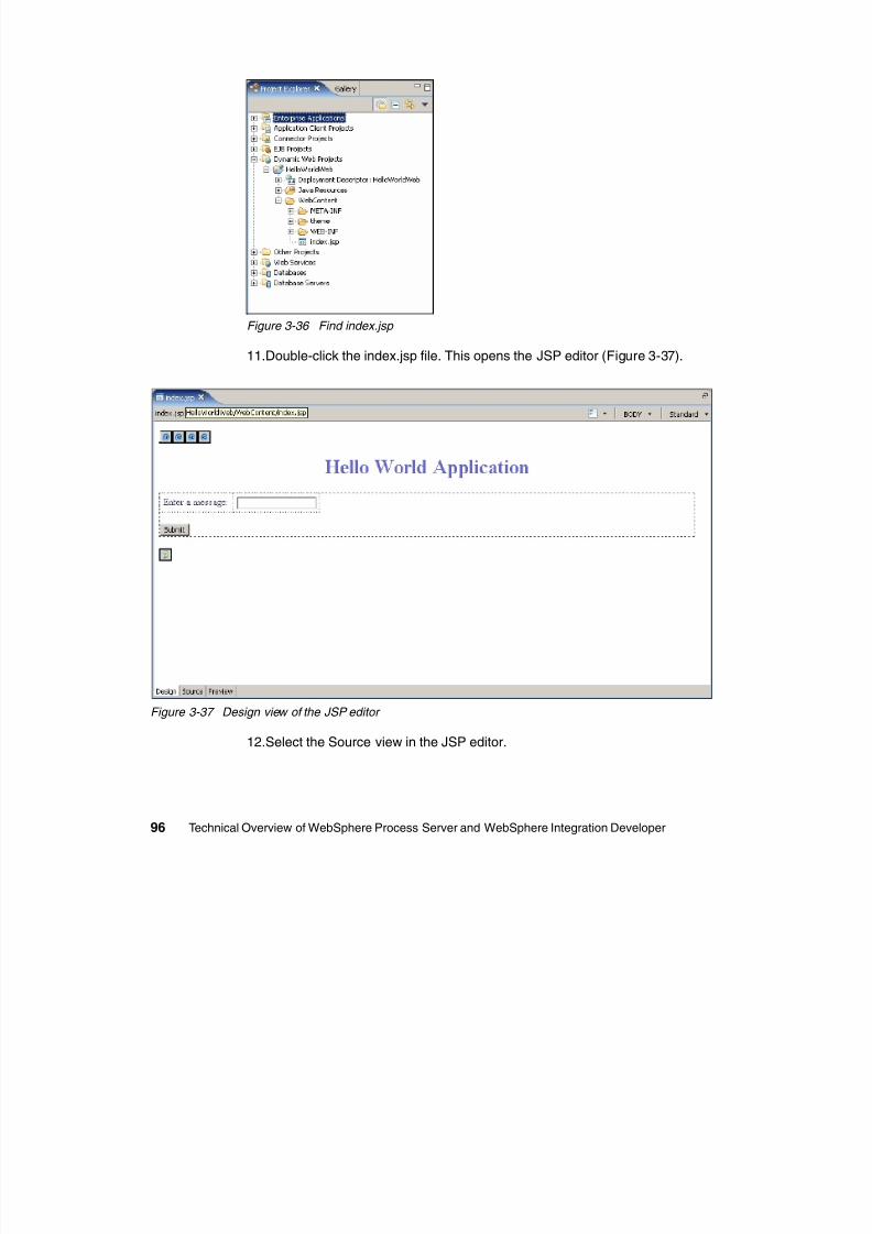
8/6/2019 WID RedBooks
http://slidepdf.com/reader/full/wid-redbooks 106/128
96 Technical Overview of WebSphere Process Server and WebSphere Integration Developer
Figure 3-36 Find index.jsp
11.Double-click the index.jsp file. This opens the JSP editor (Figure 3-37).
Figure 3-37 Design view of the JSP editor
12.Select the Source view in the JSP editor.
The portion of the JSP that actually invokes the component is shown inFigure 3-38.
<%if (request.getParameter("message") != null) {
try {
ServiceManager serviceManager = new ServiceManager();Service service = (Service) serviceManager.locateService("HelloWorldInterfacePartner");
BOFactory bofactory = (BOFactory)serviceManager.locateService("com/ibm/websphere/bo/BOFactory");
DataObject input = bofactory.createByElement("http://HelloWorld/HelloWorldInterface",
"sendMessage");
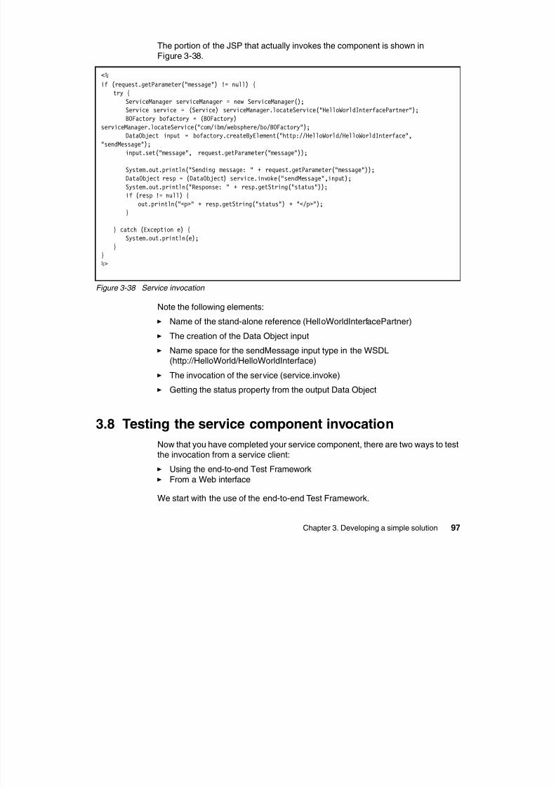
8/6/2019 WID RedBooks
http://slidepdf.com/reader/full/wid-redbooks 107/128
Chapter 3. Developing a simple solution 97
Figure 3-38 Service invocation
Note the following elements:
Name of the stand-alone reference (HelloWorldInterfacePartner)
The creation of the Data Object input
Name space for the sendMessage input type in the WSDL(http://HelloWorld/HelloWorldInterface)
The invocation of the service (service.invoke)
Getting the status property from the output Data Object
3.8 Testing the service component invocation
Now that you have completed your service component, there are two ways to testthe invocation from a service client:
Using the end-to-end Test Framework
From a Web interface
We start with the use of the end-to-end Test Framework.
g );
input.set("message", request.getParameter("message"));
System.out.println("Sending message: " + request.getParameter("message"));
DataObject resp = (DataObject) service.invoke("sendMessage",input);
System.out.println("Response: " + resp.getString("status"));if (resp != null) {
out.println("<p>" + resp.getString("status") + "</p>");}
} catch (Exception e) {
System.out.println(e);
}}
%>
3.8.1 Using the end-to-end Test Framework
The end-to-end Test Framework can be invoked on a service component fromthe assembly diagram.
Start by opening the assembly diagram:
1. From the Business Integration perspective, expand the HelloWorld project.
2. Double-click the HelloWorld module to open the assembly diagram.
3. Right-click anywhere in the assembly diagram and select Test Module from
the context menu
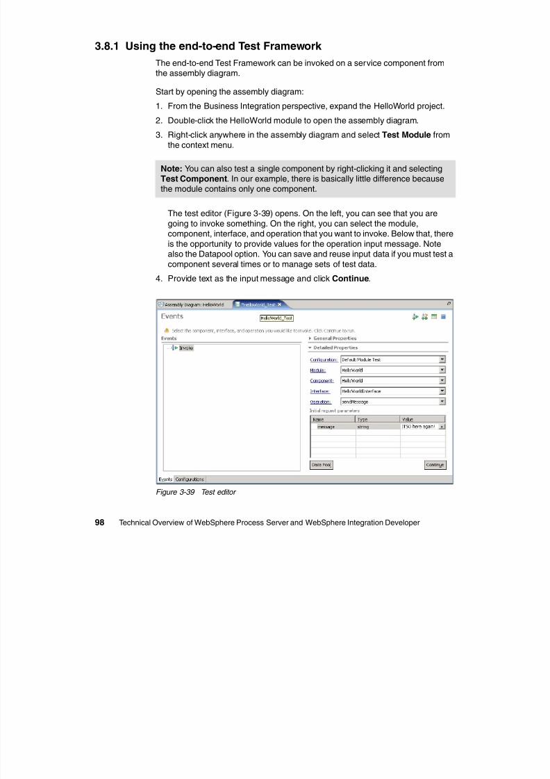
8/6/2019 WID RedBooks
http://slidepdf.com/reader/full/wid-redbooks 108/128
98 Technical Overview of WebSphere Process Server and WebSphere Integration Developer
the context menu.
The test editor (Figure 3-39) opens. On the left, you can see that you are
going to invoke something. On the right, you can select the module,component, interface, and operation that you want to invoke. Below that, there
is the opportunity to provide values for the operation input message. Notealso the Datapool option. You can save and reuse input data if you must test a
component several times or to manage sets of test data.
4. Provide text as the input message and click Continue.
Figure 3-39 Test editor
Note: You can also test a single component by right-clicking it and selectingTest Component. In our example, there is basically little difference becausethe module contains only one component.
5. In the Deployment Location dialog (Figure 3-40), verify that WebSphereProcess Server v6.0 is selected. Click Finish.
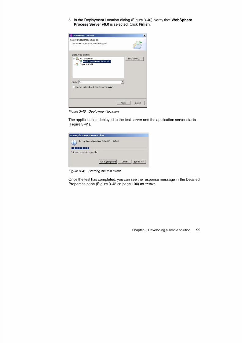
8/6/2019 WID RedBooks
http://slidepdf.com/reader/full/wid-redbooks 109/128
Chapter 3. Developing a simple solution 99
Figure 3-40 Deployment location
The application is deployed to the test server and the application server starts
(Figure 3-41).
Figure 3-41 Starting the test client
Once the test has completed, you can see the response message in the Detailed
Properties pane (Figure 3-42 on page 100) as status.
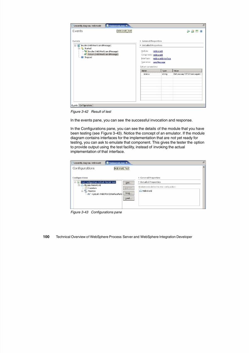
8/6/2019 WID RedBooks
http://slidepdf.com/reader/full/wid-redbooks 110/128
100 Technical Overview of WebSphere Process Server and WebSphere Integration Developer
Figure 3-42 Result of test
In the events pane, you can see the successful invocation and response.
In the Configurations pane, you can see the details of the module that you have
been testing (see Figure 3-43). Notice the concept of an emulator. If the modulediagram contains interfaces for the implementation that are not yet ready fortesting, you can ask to emulate that component. This gives the tester the option
to provide output using the test facility, instead of invoking the actualimplementation of that interface.
Figure 3-43 Configurations pane
To see the details of what is being monitored for the test run, selectHelloWorldInterfacePartner→ HelloWorld (this matches the link between our
stand-alone reference and the HelloWorld component in the assembly diagram).You can see the details in the Detailed Properties pane (Figure 3-44). Close the
test editor without saving the data from this test run.
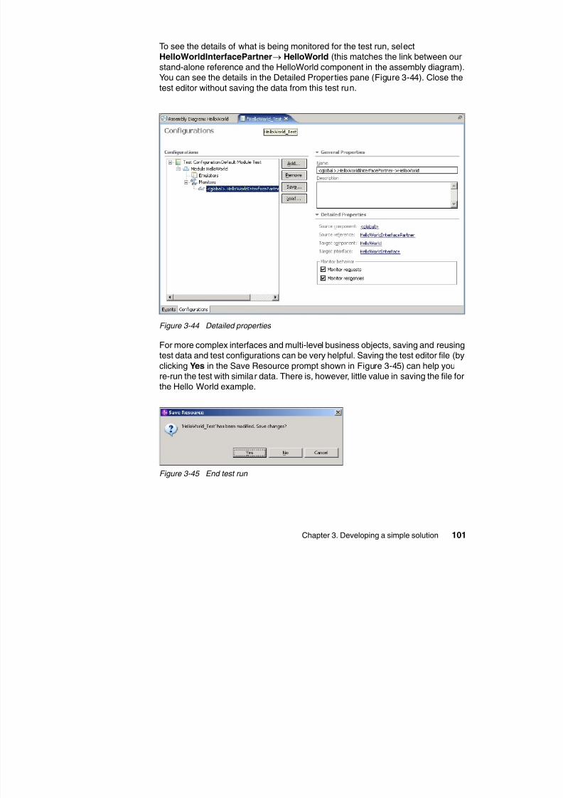
8/6/2019 WID RedBooks
http://slidepdf.com/reader/full/wid-redbooks 111/128
Chapter 3. Developing a simple solution 101
Figure 3-44 Detailed properties
For more complex interfaces and multi-level business objects, saving and reusingtest data and test configurations can be very helpful. Saving the test editor file (by
clicking Yes in the Save Resource prompt shown in Figure 3-45) can help youre-run the test with similar data. There is, however, little value in saving the file forthe Hello World example.
Figure 3-45 End test run
3.8.2 Testing from the Web interface
To test from the Web interface, you have to start the server and add the project tothe server. If you used the test client option, this has already been done. If not,follow these steps:
1. From the Server view, right-click the Server and select Start.
2. After the server has successfully started, from the Server view, right-click theserver.
3. Select Add and remove projects from the context menu.
4 Select HelloWorldApp from the list of available projects as shown in
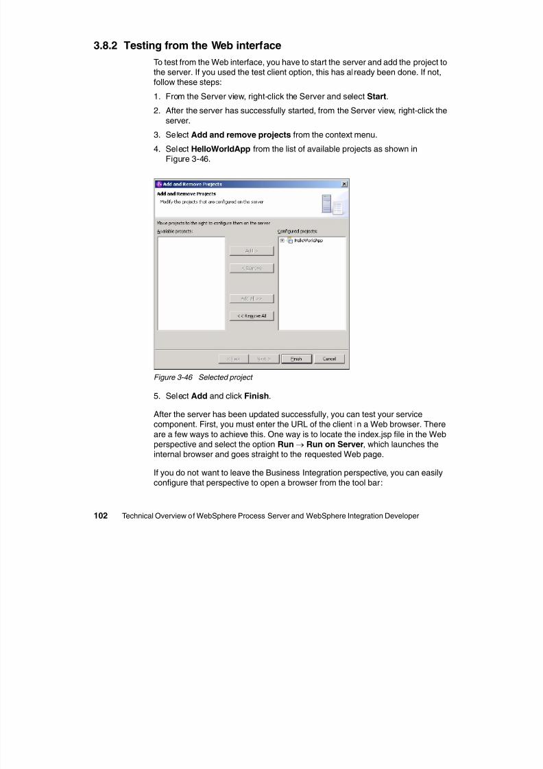
8/6/2019 WID RedBooks
http://slidepdf.com/reader/full/wid-redbooks 112/128
102 Technical Overview of WebSphere Process Server and WebSphere Integration Developer
4. Select HelloWorldApp from the list of available projects as shown inFigure 3-46.
Figure 3-46 Selected project
5. Select Add and click Finish.
After the server has been updated successfully, you can test your servicecomponent. First, you must enter the URL of the client in a Web browser. There
are a few ways to achieve this. One way is to locate the index.jsp file in the Webperspective and select the option Run→ Run on Server, which launches theinternal browser and goes straight to the requested Web page.
If you do not want to leave the Business Integration perspective, you can easilyconfigure that perspective to open a browser from the tool bar:
1. Select Window→ Customize Perspective.
2. In the Customize Perspective window (Figure 3-47), click the Commands tab.
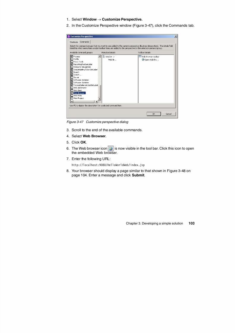
8/6/2019 WID RedBooks
http://slidepdf.com/reader/full/wid-redbooks 113/128
Chapter 3. Developing a simple solution 103
Figure 3-47 Customize perspective dialog
3. Scroll to the end of the available commands.
4. Select Web Browser.
5. Click OK.
6. The Web browser icon is now visible in the tool bar. Click this icon to openthe embedded Web browser.
7. Enter the following URL:
http://localhost:9080/HelloWorldWeb/index.jsp8. Your browser should display a page similar to that shown in Figure 3-48 on
page 104. Enter a message and click Submit.
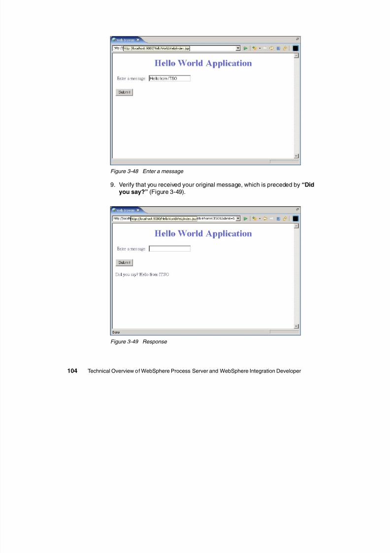
8/6/2019 WID RedBooks
http://slidepdf.com/reader/full/wid-redbooks 114/128
104 Technical Overview of WebSphere Process Server and WebSphere Integration Developer
Figure 3-48 Enter a message
9. Verify that you received your original message, which is preceded by “Didyou say?” (Figure 3-49).
Figure 3-49 Response
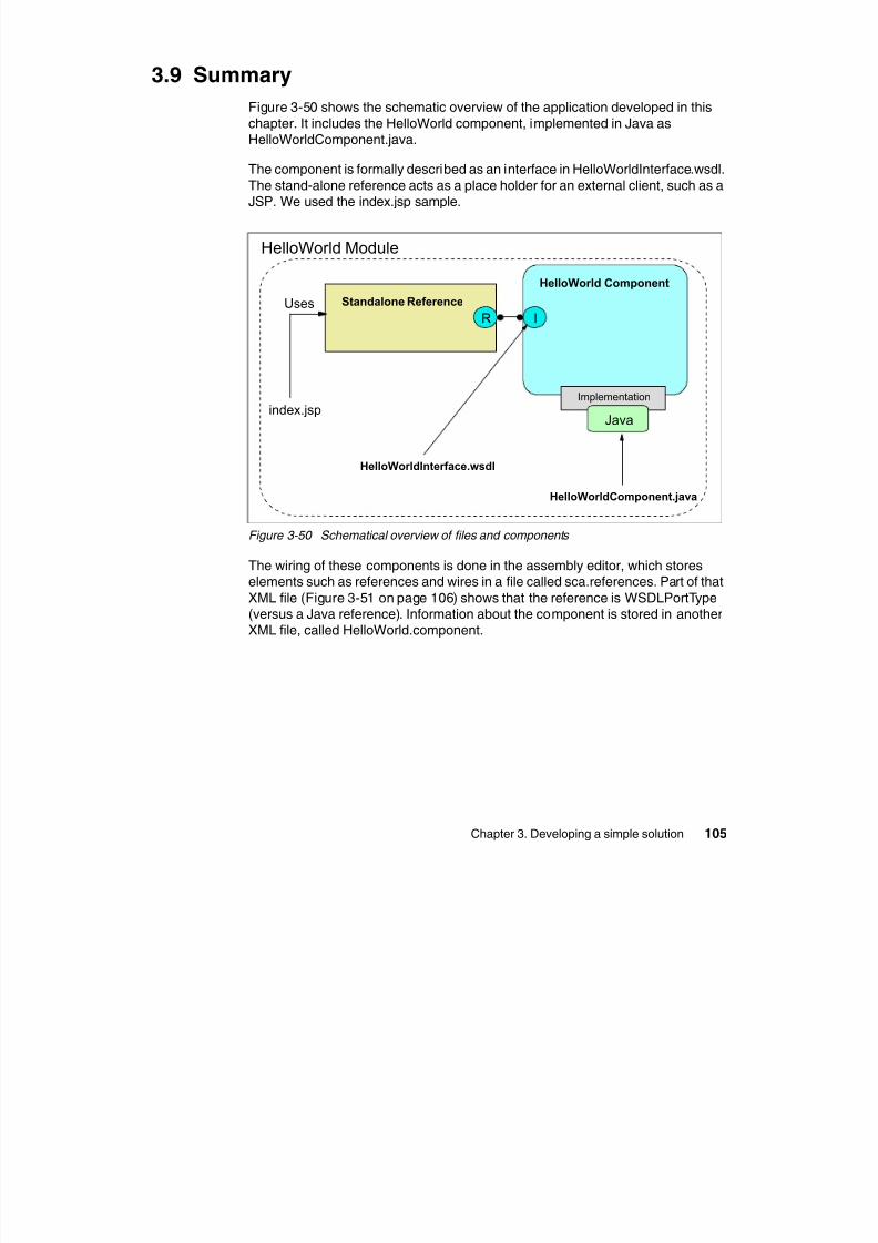
8/6/2019 WID RedBooks
http://slidepdf.com/reader/full/wid-redbooks 115/128
<scdl:references ... ><reference name="HelloWorldInterfacePartner">
<interface xsi:type="wsdl:WSDLPortType"
portType="nsl:HelloWorldInterface"/><wire target="HelloWorld"/>
</reference>
</scdl:references>
HellowWorld
Component
Stand-alone
Reference
sca.references
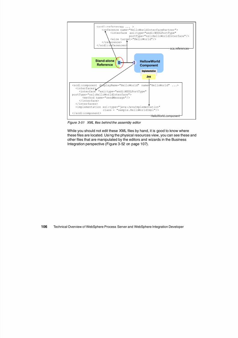
8/6/2019 WID RedBooks
http://slidepdf.com/reader/full/wid-redbooks 116/128
106 Technical Overview of WebSphere Process Server and WebSphere Integration Developer
Figure 3-51 XML files behind the assembly editor
While you should not edit these XML files by hand, it is good to know wherethese files are located. Using the physical resources view, you can see these andother files that are manipulated by the editors and wizards in the BusinessIntegration perspective (Figure 3-52 on page 107).
<scdl:component displayName="HelloWorld" name="HelloWorld" ...><interfaces>
<interface "xsi:type="wsdl:WSDLPortType"
portType="nsl:HelloWorldInterface"><method name="sendMessage"/>
</interface></interfaces>
<implementation xsi:type="java:JavaImplementation"class = "sample.HelloWorldImpl"/>
</scdl:component>HelloWorld.component
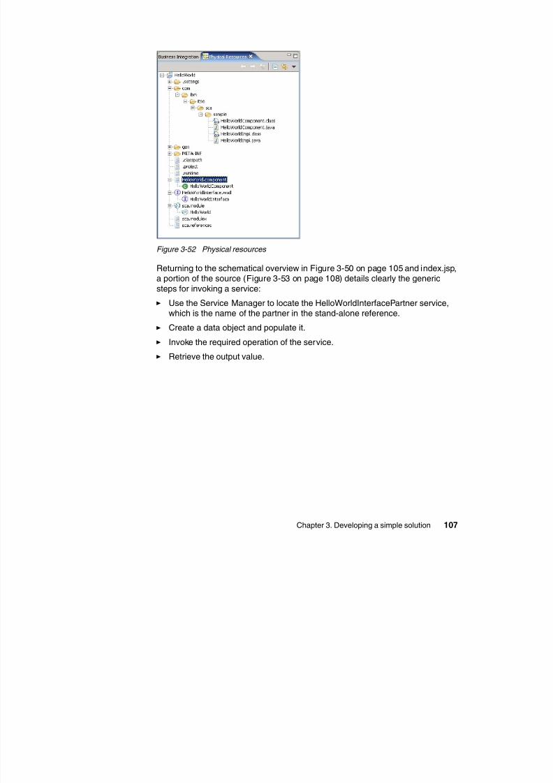
8/6/2019 WID RedBooks
http://slidepdf.com/reader/full/wid-redbooks 117/128
<%if (request.getParameter("message") != null) {
try {ServiceManager serviceManager = new ServiceManager();
Service service = (Service) serviceManager.locateService("HelloWorldInterfacePartner");
BOFactory bofactory = (BOFactory)serviceManager.locateService("com/ibm/websphere/bo/BOFactory");
DataObject input = bofactory.createByElement("http://HelloWorld/HelloWorldInterface","sendMessage");
input.set("message", request.getParameter("message"));
System.out.println("Sending message: " + request.getParameter("message"));
D t Obj t (D t Obj t) i i k (" dM " i t)
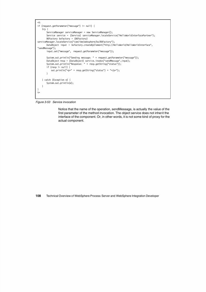
8/6/2019 WID RedBooks
http://slidepdf.com/reader/full/wid-redbooks 118/128
108 Technical Overview of WebSphere Process Server and WebSphere Integration Developer
Figure 3-53 Service invocation
Notice that the name of the operation, sendMessage, is actually the value of the
first parameter of the method invocation. The object service does not inherit theinterface of the component. Or, in other words, it is not some kind of proxy for the
actual component.
DataObject resp = (DataObject) service.invoke("sendMessage",input);System.out.println("Response: " + resp.getString("status"));
if (resp != null) {
out.println("<p>" + resp.getString("status") + "</p>");
}
} catch (Exception e) {
System.out.println(e);}
}
%>
Finally, consider the overlaid figure in Figure 3-54. At the top, you see thegraphical representation of an operation and its input and output. Below that is
the implementation of that operation as a public method in a Java class.
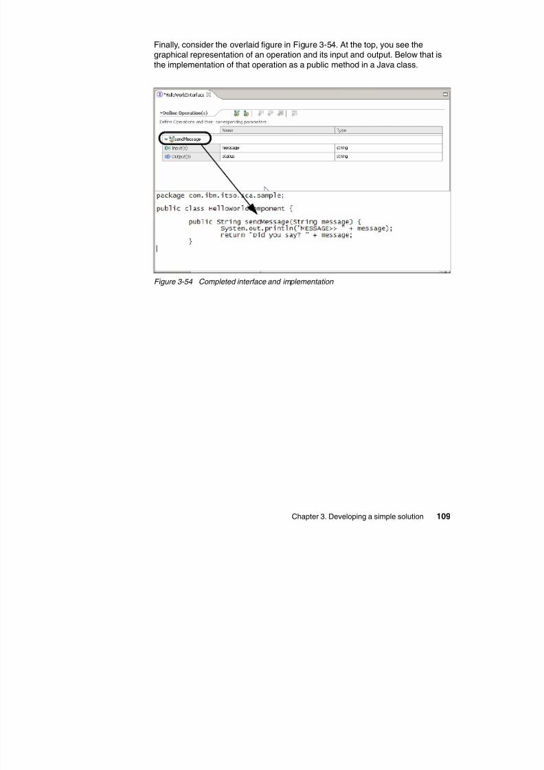
8/6/2019 WID RedBooks
http://slidepdf.com/reader/full/wid-redbooks 119/128
Chapter 3. Developing a simple solution 109
Figure 3-54 Completed interface and implementation

8/6/2019 WID RedBooks
http://slidepdf.com/reader/full/wid-redbooks 120/128
110 Technical Overview of WebSphere Process Server and WebSphere Integration Developer
A
8/6/2019 WID RedBooks
http://slidepdf.com/reader/full/wid-redbooks 121/128
© Copyright IBM Corp. 2005. All rights reserved. 111
Appendix A.
Additional material
This Redpaper refers to additional material that can be downloaded from theInternet.
Locating the Web materialThe Web material associated with this Redpaper is available in soft copy on the
Internet from the IBM Redbooks Web server. Point your Web browser to:
ftp://www.redbooks.ibm.com/redbooks/REDP4041
Alternatively, you can go to the IBM Redbooks Web site at:
ibm.com/redbooks
Select the Additional materials and open the directory that corresponds withthe redbook form number, REDP4041.
Using the Web material
The additional Web material that accompanies this Redpaper includes the fileslisted in Figure A-1 on page 112.
Table A-1 Provided Web materials
System requirements for using the Web material
The intended use of the Web materials is importing an installed copy of
File Name Description
HelloWorldComponent.java Java class written by a developer
HelloWorldImpl.java Generated Java class
index.jsp Sample JSP invoking an SCA component
HelloWorld.zip Project Interchange file
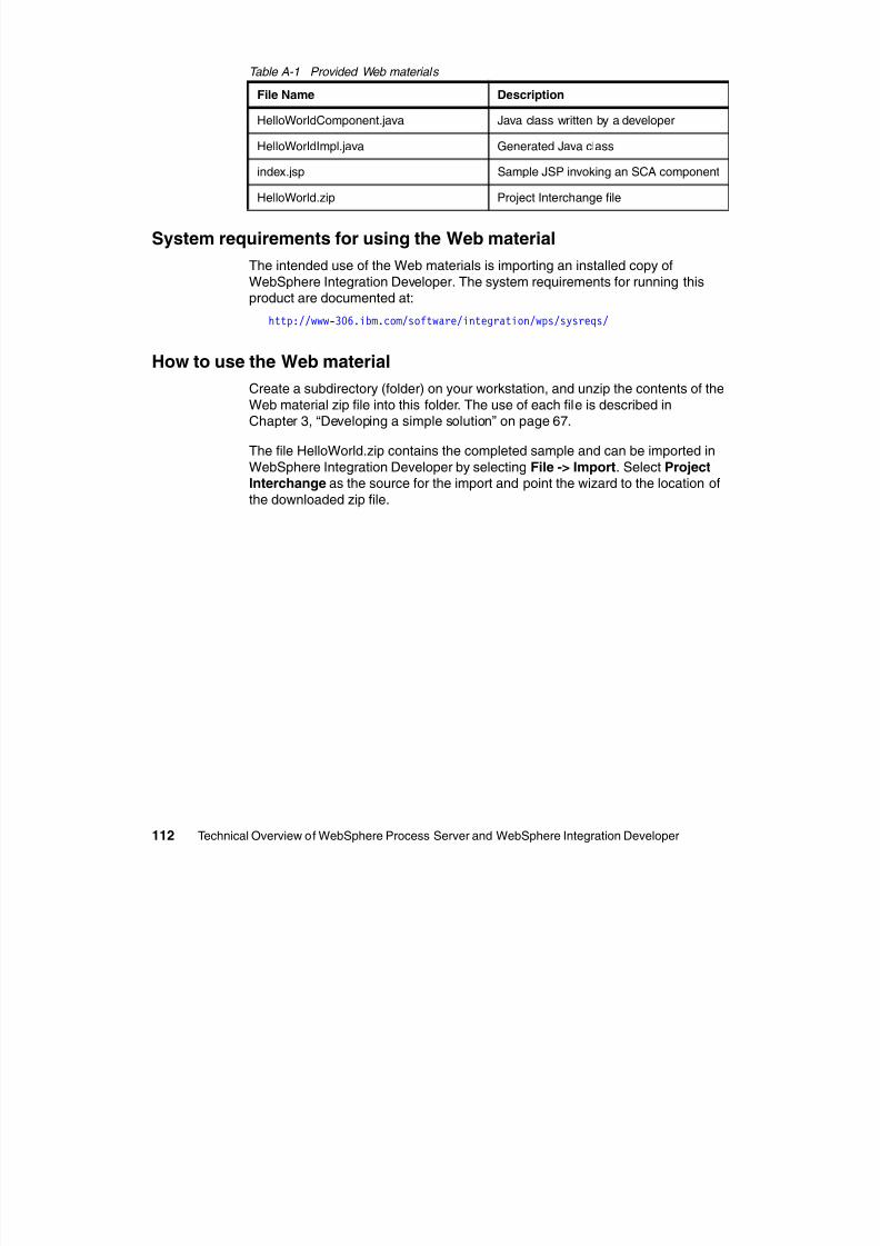
8/6/2019 WID RedBooks
http://slidepdf.com/reader/full/wid-redbooks 122/128
112 Technical Overview of WebSphere Process Server and WebSphere Integration Developer
The intended use of the Web materials is importing an installed copy of
WebSphere Integration Developer. The system requirements for running thisproduct are documented at:
http://www-306.ibm.com/software/integration/wps/sysreqs/
How to use the Web material
Create a subdirectory (folder) on your workstation, and unzip the contents of the
Web material zip file into this folder. The use of each file is described inChapter 3, “Developing a simple solution” on page 67.
The file HelloWorld.zip contains the completed sample and can be imported in
WebSphere Integration Developer by selecting File -> Import. Select Project
Interchange as the source for the import and point the wizard to the location ofthe downloaded zip file.
API Application Programming
Interface
BO Business ObjectBPEL Business Process Execution
Language
BPM Business Process
Management
Abbreviations and acronyms
LDAP Lightweight Directory Access
Protocol
OASIS Organization for theAdvancement of Structured
Information Standards
POJO Plain Old Java Object
SAX Simple API for XML
8/6/2019 WID RedBooks
http://slidepdf.com/reader/full/wid-redbooks 123/128
© Copyright IBM Corp. 2005. All rights reserved. 113
CBE Common Business Event
CEI Common Event Infrastructure
CICS Customer Information Control
System
CRM Customer Relationship
Management
EAI Enterprise Application
Integration
EIS Enterprise Information
System
ERP Enterprise Resource Planning
HTTP HyperText Transfer Protocol
HTTPS Secure HyperText Transfer
Protocol
I/O Input/Output
IBM International Business
Machines
ISV Independent Software Vendor
IT Information Technology
ITSO International Technical
Support Organization
JDBC Java Database Connectivity
JMS Java Messaging Service
JNDI Java Naming and Directory
Interface
JSF Java Server Faces
JSP JavaServer Pages
JSR Java Specification Request
SCA Service Component
Architecture
SCDL Service Component
Description LanguageSDO Service Data Object
SLA Service Level Agreement
SOA Service-oriented Architecture
SOAP Simple Object Access
Protocol
UI User Interface
URL Universal Resource Locator
VM Virtual Machine
WSDL Web Service Description
Language
WS-I Web Services Interoperability
WSDL Web Service Description
Language
XML Extensible Mark-up Language

8/6/2019 WID RedBooks
http://slidepdf.com/reader/full/wid-redbooks 124/128
114 Technical Overview of WebSphere Process Server and WebSphere Integration Developer
Related publications
The publications listed in this section are considered particularly suitable for a
more detailed discussion of the topics covered in this Redpaper.
IBM Redbooks
For information on ordering these publications, see “How to get IBM Redbooks”
on page 115 Note that some of the documents referenced here may be available
8/6/2019 WID RedBooks
http://slidepdf.com/reader/full/wid-redbooks 125/128
© Copyright IBM Corp. 2005. All rights reserved. 115
on page 115. Note that some of the documents referenced here may be availablein soft copy only.
Patterns: Serial and Parallel Processes for Process Choreography and
Workflow, SG24-6306 Patterns: SOA with an Enterprise Service Bus in WebSphere Application
Server V6 , SG24-6494
Online resources
These Web sites and URLs are also relevant as further information sources:
Business Process Execution Language (BPEL) Specificationhttp://www.ibm.com/developerworks/webservices/library/specification/ws-bpel
Service Data Object (SDO) Specification
http://www.ibm.com/developerworks/java/library/j-commonj-sdowmt/
WebSphere Process Server InfoCenter
http://www-306.ibm.com/software/integration/wps/library/infocenter/
How to get IBM Redbooks
You can search for, view, or download Redbooks, Redpapers, Hints and Tips,draft publications and Additional materials, as well as order hardcopy Redbooks
or CD-ROMs, at this Web site:
ibm.com/redbooks
Help from IBM
IBM Support and downloads
ibm.com/support
IBM Global Services
ibm.com/services
8/6/2019 WID RedBooks
http://slidepdf.com/reader/full/wid-redbooks 126/128
116 Technical Overview of WebSphere Process Server and WebSphere Integration Developer

8/6/2019 WID RedBooks
http://slidepdf.com/reader/full/wid-redbooks 127/128
®
Redpaper
Technical Overview ofWebSphere Process Server and
WebSphere IntegrationDeveloper
Back cover
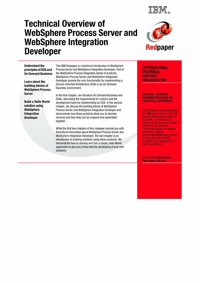
8/6/2019 WID RedBooks
http://slidepdf.com/reader/full/wid-redbooks 128/128
INTERNATIONALTECHNICAL
SUPPORTORGANIZATION
BUILDING TECHNICALINFORMATION BASED ONPRACTICAL EXPERIENCE
IBM Redbooks are developed bythe IBM International TechnicalSupport Organization. Expertsfrom IBM, Customers andPartners from around the worldcreate timely technicalinformation based on realisticscenarios. Specificrecommendations are providedto help you implement IT
solutions more effectively inyour environment.
For more information:ibm.com /redbooks
Understand the
principles of SOA and
On Demand Business
Learn about the
building blocks of
WebSphere Process
Server
Build a Hello World
solution using
WebSphereIntegration
Developer
This IBM Redpaper is a technical introduction to WebSphere
Process Server and WebSphere Integration Developer. Part of
the WebSphere Process Integration family of products,
WebSphere Process Server and WebSphere IntegrationDeveloper provide the core functionality for implementing a
Service-Oriented Architecture (SOA) in an On Demand
Business environment.
In the first chapter, we introduce On Demand Business and
SOAs, describing the requirements for runtime and the
development tools for implementing an SOA. In the second
chapter, we discuss the building blocks of WebSphere
Process Server and WebSphere Integration Developer anddemonstrate how these products allow you to develop
services and how they can be mapped and assembled
together.
While the first two chapters of this redpaper provide you with
theoretical information about WebSphere Process Server and
WebSphere Integration Developer, the last chapter is an
introduction to building solutions using these products. We
demonstrate how to develop and test a classic Hello Worldapplication to give you a head start for developing of your own
solutions.