Embed Size (px)
Citation preview

© 2016 Wi-Fi Alliance. All Rights Reserved. Used with the permission of Wi-Fi Alliance under the terms set forth above.
Wi-Fi Peer-to-Peer (P2P)
Technical Specification
Version 1.7
This document is the specification for the Wi-Fi Alliance Wi-Fi CERTIFIED Wi-Fi Direct® program, which allows Wi-Fi client devices to connect directly without the use of an access point.
WI-FI ALLIANCE PROPRIETARY – SUBJECT TO CHANGE WITHOUT NOTICE
This document may be used with the permission of Wi-Fi Alliance under the terms set forth herein.
By your use of the document, you are agreeing to these terms. Unless this document is clearly designated as an approved specification, this document is a work in process and is not an approved Wi-Fi Alliance specification. This document is subject to revision or removal at any time without notice. Information contained in this document may be used at your sole risk. Wi-Fi Alliance assumes no responsibility for errors or omissions in this document. This copyright permission does not constitute an endorsement of the products or services. Wi-Fi Alliance trademarks and certification marks may not be used unless specifically allowed by Wi-Fi Alliance.
Wi-Fi Alliance has not conducted an independent intellectual property rights ("IPR") review of this document and the information contained herein, and makes no representations or warranties regarding IPR, including without limitation patents, copyrights or trade secret rights. This document may contain inventions for which you must obtain licenses from third parties before making, using or selling the inventions.
Wi-Fi Alliance owns the copyright in this document and reserves all rights therein. A user of this document may duplicate and distribute copies of the document in connection with the authorized uses described herein, provided any duplication in whole or in part includes the copyright notice and the disclaimer text set forth herein. Unless prior written permission has been received from Wi-Fi Alliance, any other use of this document and all other duplication and distribution of this document are prohibited. Unauthorized use, duplication, or distribution is an infringement of Wi-Fi Alliance’s copyright.
NO REPRESENTATIONS OR WARRANTIES (WHETHER EXPRESS OR IMPLIED) ARE MADE BY WI-FI ALLIANCE AND WI-FI ALLIANCE IS NOT LIABLE FOR AND HEREBY DISCLAIMS ANY DIRECT, INDIRECT, PUNITIVE, SPECIAL, INCIDENTAL, CONSEQUENTIAL, OR EXEMPLARY DAMAGES ARISING OUT OF OR IN CONNECTION WITH THE USE OF THIS DOCUMENT AND ANY INFORMATION CONTAINED IN THIS DOCUMENT.

Wi-Fi Peer-to-Peer (P2P) Technical Specification v1.7
© 2016 Wi-Fi Alliance. All Rights Reserved. Used with the permission of Wi-Fi Alliance under the terms as stated in this document.
Page 2 of 201
Document History
Version Date Status Comments
1.0 2009-12-09 Approved for Internal Release
Peer-to-Peer Technical Specification v1.00
1.1 2010-10-04 Final Public release version
1.2 2011-12-14 Final Public release version
- Incorporated changes in 3.1.2.1.2, 3.1.2.1.3, 3.2.2, 3.3.2.2, 3.3.3.2, 4.1.14, 4.1.16, 4.2.1 (Table 37), 4.2.3 (Table 41) as documented in Draft Errata v0-1 for WiFi_P2P_Technical_Specification_v1-1.pdf
- Incorporated proposed language for response time requirement addition in 3.1.5.1 and 3.2.3
- Incorporated editorial fix to Appendix C (Figure C12)
- Updated WSC Primary Device Type attribute table in Appendix B.2 to incorporated new “tablet” sub category (WSC v2.0.1).
- Added Display Service Protocol Type in Table 63
1.3 Draft Internal draft, not publicly released
1.3.32 2014-01-27 Draft Draft release version to public
- Updated to support NFC
1.4 2014-03-21 Final Public release version
- Clarifications on NFC sections
- Updated to incorporate the Wi-Fi Peer-to-Peer Services Addendum version 0.7
- Minor editorial corrections/clarifications
1.5 2014-08-04 Final Public release version
- Editorial updates to clarify references to Wi-Fi Peer-to-Peer Services (P2Ps) Specification
1.6 2016-01-14 Final Corrected missing reference in section 4.2.11.1
1.7 2016-07-06 Final Public release version
- Updated to incorporate operation in the DMG (60GHz)

Wi-Fi Peer-to-Peer (P2P) Technical Specification v1.7
© 2016 Wi-Fi Alliance. All Rights Reserved. Used with the permission of Wi-Fi Alliance under the terms as stated in this document.
Page 3 of 201
Table of Contents
1 Introduction ............................................................................................................ 13
1.1 Overview .................................................................................................. 13
1.2 Scope....................................................................................................... 13
1.3 References .............................................................................................. 13
1.4 Definitions ................................................................................................ 14
1.5 Abbreviations and acronyms .................................................................... 16
2 Architectural overview ............................................................................................ 19
2.1 P2P components ..................................................................................... 19
2.2 P2P topology ........................................................................................... 19
2.3 Concurrent operation ............................................................................... 21
2.4 Functions and services ............................................................................ 22
2.4.1 Basic functions and services .................................................................... 22
2.4.2 P2P specific functions and services ......................................................... 23
2.4.3 P2P Device addressing............................................................................ 23
3 Functional description and procedures .................................................................. 25
3.1 P2P discovery .......................................................................................... 25
3.1.1 Introduction .............................................................................................. 25
3.1.2 Device Discovery procedures .................................................................. 25
3.1.3 Service Discovery procedures ................................................................. 38
3.1.4 Group Formation procedure ..................................................................... 44
3.1.5 P2P Invitation procedure .......................................................................... 54
3.2 P2P Group operation ............................................................................... 58
3.2.1 P2P Group ID .......................................................................................... 59
3.2.2 Starting and maintaining a P2P Group session ....................................... 59
3.2.3 Connecting to a P2P Group ..................................................................... 61
3.2.4 P2P Group Owner services for P2P Client discovery .............................. 62
3.2.5 Persistent Group operation ...................................................................... 64
3.2.6 Communication in a P2P Group .............................................................. 66
3.2.7 Disconnecting from a P2P Group ............................................................ 69
3.2.8 Disconnecting a P2P Client ..................................................................... 69

Wi-Fi Peer-to-Peer (P2P) Technical Specification v1.7
© 2016 Wi-Fi Alliance. All Rights Reserved. Used with the permission of Wi-Fi Alliance under the terms as stated in this document.
Page 4 of 201
3.2.9 Ending a P2P Group session ................................................................... 70
3.3 P2P Power Management ......................................................................... 70
3.3.1 Introduction .............................................................................................. 70
3.3.2 Power Management and discovery .......................................................... 71
3.3.3 Power Management at a P2P Group Owner ............................................ 72
3.3.4 Power Management at a P2P Client ........................................................ 79
3.4 Managed P2P Device operations ............................................................ 83
3.4.1 Managed P2P Device capability .............................................................. 83
3.4.2 P2P Coexistence Parameters operations ................................................ 84
3.4.3 WLAN Deauthentication/Disassociation................................................... 86
3.4.4 Managed P2P Device Summary .............................................................. 87
4 Frame formats ........................................................................................................ 89
4.1 P2P Information Element ......................................................................... 89
4.1.1 P2P IE format .......................................................................................... 89
4.1.2 Status attribute ......................................................................................... 92
4.1.3 Minor Reason Code attribute ................................................................... 93
4.1.4 P2P Capability attribute ........................................................................... 94
4.1.5 P2P Device ID attribute............................................................................ 97
4.1.6 Group Owner Intent attribute ................................................................... 97
4.1.7 Configuration Timeout attribute ................................................................ 98
4.1.8 Listen Channel attribute ........................................................................... 98
4.1.9 P2P Group BSSID attribute ..................................................................... 99
4.1.10 Extended Listen Timing attribute ........................................................... 100
4.1.11 Intended P2P Interface Address attribute .............................................. 100
4.1.12 P2P Manageability attribute ................................................................... 101
4.1.13 Channel List attribute ............................................................................. 102
4.1.14 Notice of Absence attribute .................................................................... 103
4.1.15 P2P Device Info attribute ....................................................................... 105
4.1.16 P2P Group Info attribute ........................................................................ 106
4.1.17 P2P Group ID attribute........................................................................... 107
4.1.18 P2P Interface attribute ........................................................................... 108
4.1.19 Operating Channel attribute ................................................................... 108
4.1.20 Invitation Flags attribute ......................................................................... 109

Wi-Fi Peer-to-Peer (P2P) Technical Specification v1.7
© 2016 Wi-Fi Alliance. All Rights Reserved. Used with the permission of Wi-Fi Alliance under the terms as stated in this document.
Page 5 of 201
4.1.21 Out-of-Band Group Owner Negotiation Channel attribute...................... 110
4.1.22 Service Hash attribute............................................................................ 111
4.1.23 Session Information Data Info ................................................................ 111
4.1.24 Connection Capability Info attribute ....................................................... 112
4.1.25 Advertisement ID Info attribute .............................................................. 112
4.1.26 Advertised Service Info attribute ............................................................ 113
4.1.27 Session ID Info attribute......................................................................... 114
4.1.28 Feature Capability Info attribute ............................................................. 115
4.1.29 Persistent Group Info attribute ............................................................... 115
4.2 Management Frames ............................................................................. 116
4.2.1 Beacon frame format ............................................................................. 116
4.2.2 Probe Request frame format .................................................................. 117
4.2.3 Probe Response frame format ............................................................... 118
4.2.4 Association/Reassociation Request frame format ................................. 119
4.2.5 Association/Reassociation Response frame format ............................... 120
4.2.6 Deauthentication frame format ............................................................... 120
4.2.7 Disassociation frame format .................................................................. 121
4.2.8 IP Address Allocation in EAPOL-Key Frames (4-Way Handshake) ....... 121
4.2.9 P2P public action frames ....................................................................... 122
4.2.10 P2P action frames ................................................................................. 132
4.2.11 Service Discovery action frames ............................................................ 134
4.2.12 FST action frames ................................................................................. 137
4.3 DMG Frames ......................................................................................... 137
4.3.1 DMG Beacon and Announce frame format ............................................ 137
4.3.2 Information request frame format ........................................................... 138
4.3.3 Information response frame format ........................................................ 139
4.4 Frame Usage ......................................................................................... 139
4.5 NFC NDEF Structure ............................................................................. 142
4.5.1 NFC P2P Handover Request Message ................................................. 142
4.5.2 NFC P2P Handover Select Message ..................................................... 145
Appendix A P2P State Machine .................................................................................. 148
Appendix B P2P Specific WSC IE Attributes ............................................................... 157
B.1 Requested Device Type......................................................................... 157

Wi-Fi Peer-to-Peer (P2P) Technical Specification v1.7
© 2016 Wi-Fi Alliance. All Rights Reserved. Used with the permission of Wi-Fi Alliance under the terms as stated in this document.
Page 6 of 201
B.2 Primary Device Type.............................................................................. 158
Appendix C GAS Frame Field Value ........................................................................... 159
C.1 GAS Initial Request action frame ........................................................... 159
C.2 GAS Initial Response Action Frame ...................................................... 161
C.3 GAS Fragmentation ............................................................................... 163
Appendix D P2P Discovery Diagrams ......................................................................... 167
Appendix E Recommended Practices for Bonjour using Wi-Fi P2P Service Discovery 184
E.1 Example for Apple File Sharing over TCP ............................................. 186
E.2 Example for IP Printing over TCP .......................................................... 189
E.3 DNS Name Compression ....................................................................... 192
E.4 Supported Service Type Hash (SSTH) .................................................. 193
Appendix F Recommended Practices for UPnP using Wi-Fi P2P Service Discovery . 195
F.1 Example 1—Search for UPnP internet gateway devices ....................... 197
F.2 Example 2—Search for all UPnP root devices ....................................... 198
F.3 Example 3—Search for a specific device by its UUID ........................... 198
F.4 Example 4—Search for all instances of a UPnP Media Server Content Directory Service ..................................................................................................... 199
Appendix G Recommended Practices for Peer-to-Peer Services (P2Ps) using P2P Service Discovery........................................................................................................ 200

Wi-Fi Peer-to-Peer (P2P) Technical Specification v1.7
© 2016 Wi-Fi Alliance. All Rights Reserved. Used with the permission of Wi-Fi Alliance under the terms as stated in this document.
Page 7 of 201
Figures
Figure 1—P2P components and topology when operating outside DMG...................... 20
Figure 2—P2P components and topology when operating within DMG ........................ 20
Figure 3—A subset of P2P 1:n topology (n=1) .............................................................. 21
Figure 4—P2P Concurrent device ................................................................................. 21
Figure 5—Example In-band Device Discovery procedures for a P2P Device operating outside DMG ................................................................................................................. 31
Figure 6—Example In-band Device Discovery procedures for a P2P Device operating within DMG .................................................................................................................... 32
Figure 7—Out-of-Band Device Discovery (NFC Negotiated Handover) ........................ 36
Figure 8—Out-of-Band Device Discovery (NFC Static Handover) ................................ 38
Figure 9—Example of Service Discovery procedure when operating outside DMG ...... 43
Figure 10—Example of Service Discovery procedure when operating within DMG ...... 44
Figure 11—Group Owner Negotiation message exchange ........................................... 47
Figure 12—Group Owner determination flowchart ........................................................ 48
Figure 13—Example of Group Formation using NFC Out-of-Band Device Discovery ... 54
Figure 14—Example of P2P Group Owner Opportunistic Power Save ......................... 73
Figure 15—P2P Group Owner Notice of Absence ........................................................ 75
Figure 16—P2P Group Owner Notice of Absence with Opportunistic Power Save ....... 77
Figure 17—Illustration of P2P Group Owner power save state precedence rules ......... 78
Figure 18—Example P2P WMM-PS operation with P2P Group Owner NoA ................ 80
Figure 19—Shortening of P2P WMM-PS USPs by P2P Group Owner absence ........... 81
Figure 20—P2P Presence Request-Response procedure ............................................ 82
Figure 21—Managed P2P Device that is a P2P Concurrent Device ............................. 84
Figure 22—Example of P2P attributes carried in two P2P IEs ...................................... 92
Figure 23—NFC P2P Handover Request Message .................................................... 143
Figure 24—NFC P2P Handover Select Message ....................................................... 146
Figure A1—P2P State Machine .................................................................................. 149
Figure C1—GAS Initial Request Action Frame Format ............................................... 159
Figure C2—Advertisement Protocol Information Element ........................................... 159
Figure C3—ANQP Query Request Field ..................................................................... 160
Figure C4—ANQP Query Request Frame Vendor-specific Content ........................... 160

Wi-Fi Peer-to-Peer (P2P) Technical Specification v1.7
© 2016 Wi-Fi Alliance. All Rights Reserved. Used with the permission of Wi-Fi Alliance under the terms as stated in this document.
Page 8 of 201
Figure C5—GAS Initial Response Action Frame Format ............................................ 161
Figure C6—Advertisement Protocol Information Element ........................................... 162
Figure C7—ANQP Query Response Field Format ...................................................... 162
Figure C8—ANQP Query Response Frame Vendor-specific Content Field ................ 163
Figure C9—GAS Comeback Request Frame Format ................................................. 164
Figure C10—GAS Comeback Response Frame Format ............................................. 164
Figure C11—Advertisement Protocol IE ...................................................................... 165
Figure C12—Example GAS Fragmentation Frame Exchange Sequence ................... 166
Figure E1—Query Request Vendor-specific Content .................................................. 184
Figure E2—Bonjour Query Data ................................................................................. 184
Figure E3—Query Response Vendor-specific Content ............................................... 185
Figure E4—Response Data ........................................................................................ 185
Figure E5—AFP Over TCP Query Data (human readable) ......................................... 186
Figure E6—AFP Over TCP Query Data (encoded and compressed).......................... 187
Figure E7—AFP over TCP Response Data (human readable) ................................... 187
Figure E8—AFP over TCP Response Data (encoded and compressed) .................... 187
Figure E9—AFP Over TCP Query Data for Example (human readable) ..................... 188
Figure E10—AFP Over TCP Query Data for Example (encoded and compressed) ... 188
Figure E11—AFP over TCP Response Data for Example (human readable) ............. 188
Figure E12—AFP over TCP Response Data for Example (encoded and compressed) .................................................................................................................................... 189
Figure E13—IPP Over TCP Query Data (human readable) ........................................ 189
Figure E14—IPP Over TCP Query Data (encoded and compressed) ......................... 189
Figure E15—IPP over TCP Response Data (human readable) .................................. 190
Figure E16—IPP over TCP Response Data (encoded and compressed) ................... 190
Figure E17—IPP Over TCP Query Data for MyPrinter (human readable)................... 191
Figure E18—IPP Over TCP Query Data for MyPrinter (encoded and compressed) ... 191
Figure E19—IPP over TCP Response Data for MyPrinter (human readable) ............. 191
Figure E20—IPP over TCP Response Data for MyPrinter (encoded and compressed) .................................................................................................................................... 192
Figure F1—Vendor-specific Content in ANQP Query Request ................................... 196
Figure F2—Vendor-specific content in ANQP Query Response ................................. 196
Figure F3—Query Data ............................................................................................... 196

Wi-Fi Peer-to-Peer (P2P) Technical Specification v1.7
© 2016 Wi-Fi Alliance. All Rights Reserved. Used with the permission of Wi-Fi Alliance under the terms as stated in this document.
Page 9 of 201
Figure F4—Response Data ......................................................................................... 196
Figure F5—Query Request for UPnP Internet Gateway Devices ................................ 198
Figure F6—Query Response for UPnP Internet Gateway Devices ............................. 198
Figure F7—Query Request for all UPnP root devices ................................................. 198
Figure F8—Query Response for all UPnP root devices .............................................. 198
Figure F9—Query Request for a UPnP device by its UUID ........................................ 199
Figure F10—Query Response for a UPnP device by its UUID .................................... 199
Figure F11—Query Request for all instances of a UPnP Media Server CDS ............. 199
Figure F12—Query Response for all instances of a UPnP Media Server CDS ........... 199

Wi-Fi Peer-to-Peer (P2P) Technical Specification v1.7
© 2016 Wi-Fi Alliance. All Rights Reserved. Used with the permission of Wi-Fi Alliance under the terms as stated in this document.
Page 10 of 201
Tables
Table 1—Summary of WSC Config Methods and Device Password ID usage ............. 46
Table 2—P2P Coexistence Parameters setting ............................................................ 85
Table 3—Summary of requirements on Managed P2P Devices ................................... 87
Table 4—P2P IE format ................................................................................................ 89
Table 5—General format of P2P attribute ..................................................................... 90
Table 6—P2P Attribute ID definitions ............................................................................ 90
Table 7—Status attribute format ................................................................................... 92
Table 8—Status Code definitions .................................................................................. 93
Table 9—Minor Reason Code attribute format .............................................................. 93
Table 10—Minor Reason Code definitions .................................................................... 94
Table 11—P2P Capability attribute format .................................................................... 94
Table 12—Device Capability Bitmap definition .............................................................. 95
Table 13—Group Capability Bitmap definition ............................................................... 95
Table 14—P2P Device ID attribute format .................................................................... 97
Table 15—Group Owner Intent attribute format ............................................................ 97
Table 16—GO Intent field definition .............................................................................. 98
Table 17—Configuration Timeout attribute format ........................................................ 98
Table 18—Listen Channel attribute format .................................................................... 99
Table 19—P2P Group BSSID attribute format .............................................................. 99
Table 20—Extended Listen Timing attribute format .................................................... 100
Table 21—Intended P2P Interface Address attribute format ....................................... 100
Table 22—P2P Manageability attribute format ............................................................ 101
Table 23—Manageability Bitmap field format .............................................................. 101
Table 24—Channel List attribute format ...................................................................... 102
Table 25—Channel Entry field format ......................................................................... 102
Table 26—Notice of Absence attribute format ............................................................. 103
Table 27— CTWindow and OppPS Parameters field format ....................................... 104
Table 28—Notice of Absence Descriptor format ......................................................... 104
Table 29—Device Info attribute format ........................................................................ 105
Table 30—P2P Group Info attribute format ................................................................. 106

Wi-Fi Peer-to-Peer (P2P) Technical Specification v1.7
© 2016 Wi-Fi Alliance. All Rights Reserved. Used with the permission of Wi-Fi Alliance under the terms as stated in this document.
Page 11 of 201
Table 31—P2P Client Info Descriptor format .............................................................. 106
Table 32—P2P Group ID attribute format ................................................................... 107
Table 33—P2P Interface attribute format .................................................................... 108
Table 34—Operating Channel attribute format ............................................................ 108
Table 35—Invitation Flags attribute format .................................................................. 109
Table 36—Invitation Flags Bitmap definition ............................................................... 109
Table 37— Out-of-Band Group Owner Negotiation Channel attribute format ............. 110
Table 38— Role indication field ................................................................................... 110
Table 39 – Service Hash attribute format .................................................................... 111
Table 40 - Session Information Data Info attribute format ........................................... 112
Table 41 - Connection Capability Info attribute format ................................................ 112
Table 42 - Advertisement ID Info attribute format ........................................................ 113
Table 43 - Advertised Service Info Attribute format ..................................................... 114
Table 44 - Advertised Service Descriptor format ......................................................... 114
Table 45 - Session ID Info Attribute definitions ........................................................... 115
Table 46 - Feature Capability Info attribute format ...................................................... 115
Table 47 - Persistent Group Info Attribute format ........................................................ 116
Table 48—P2P attributes in the Beacon frame ........................................................... 116
Table 49—Probe Request frame format ...................................................................... 117
Table 50—Additional attributes in WSC IE in the Probe Request frame ..................... 117
Table 51—P2P attributes in the Probe Request frame................................................ 118
Table 52—P2P attributes in the Probe Response frame ............................................. 118
Table 53—P2P attributes in the Association/Reassociation Request frame ............... 119
Table 54—P2P attributes in the Association/Reassociation Request frame sent to a WLAN AP by a Managed P2P Device ......................................................................... 120
Table 55—P2P attributes in the Association/Reassociation Response frame ............. 120
Table 56—P2P attributes in the Deauthentication frame............................................. 120
Table 57—P2P attributes in the Disassociation frame ................................................ 121
Table 58—IP Address Request KDE in the EAPOL-Key frame 2 ............................... 121
Table 59—IP Allocation KDE in the EAPOL-Key frame 3 ........................................... 122
Table 60—General format of P2P public action frame ................................................ 122
Table 61—P2P public action frame type ..................................................................... 122
Table 62—P2P attributes in the GO Negotiation Request frame ................................ 123
Wi-Fi Peer-to-Peer (P2P) Technical Specification v1.7
© 2016 Wi-Fi Alliance. All Rights Reserved. Used with the permission of Wi-Fi Alliance under the terms as stated in this document.
Page 12 of 201
Table 63—WSC IE in the GO Negotiation Request frame .......................................... 124
Table 64—P2P attributes in the GO Negotiation Response frame .............................. 124
Table 65—WSC IE in the GO Negotiation Response frame ....................................... 125
Table 66—P2P attributes in the GO Negotiation Confirmation frame ......................... 126
Table 67—P2P attributes in the P2P Invitation Request frame ................................... 126
Table 68—WSC IE in the P2P Invitation Request Frame ............................................ 127
Table 69—P2P attributes in the P2P Invitation Response frame ................................ 127
Table 70—P2P attributes in the Device Discoverability Request frame ...................... 128
Table 71—P2P attributes in the Device Discoverability Response frame ................... 128
Table 72—P2P attributes in the Provision Discovery Request frame .......................... 129
Table 73 - P2P attributes in the Provision Discovery Response frame ....................... 131
Table 74—General format of P2P action frame .......................................................... 132
Table 75—P2P action frame type ............................................................................... 132
Table 76—Service Discovery Vendor-specific Content ............................................... 134
Table 77—Service Request TLV Fields ...................................................................... 134
Table 78—Service Protocol Types .............................................................................. 135
Table 79—Service Response TLV Fields .................................................................... 136
Table 80—Service Discovery Status Codes ................................................................ 136
Table 81—P2P attributes in FST Setup Request and FST Setup Response frames .. 137
Table 82—P2P attributes in the DMG Beacon and Announce frames ........................ 137
Table 83—Information Request frame format ............................................................. 138
Table 84—Additional WSC IE attributes for the Information Request frame ............... 138
Table 85—P2P IE attributes for the Information Request frame ................................. 138
Table 86—P2P IE attributes for the Information Response frame ............................... 139
Table 87—Frame subtype usage ................................................................................ 140
Table 88—Mandatory WSC attributes in the Wi-Fi P2P Carrier Configuration Record 144
Table 89—P2P attributes in the Wi-Fi P2P Carrier Configuration Record ................... 144
Table F1— Query Values ............................................................................................ 197
Table G1 - Query Data format in ANQP Query Request Frame Vendor-Specific Content for P2Ps ...................................................................................................................... 200
Table G2 - Response Data format in ANQP Query Response Vendor-specific Content for P2Ps ...................................................................................................................... 201
Table G3 - Service Info Descriptor format ................................................................... 201

Wi-Fi Peer-to-Peer (P2P) Technical Specification v1.7
© 2016 Wi-Fi Alliance. All Rights Reserved. Used with the permission of Wi-Fi Alliance under the terms as stated in this document.
Page 13 of 201
1 Introduction
1.1 Overview
This document is the Technical Specification for Wi-Fi P2P, a solution for Wi-Fi® device-to-device connectivity. This Specification defines an architecture and set of protocols that facilitate Wi-Fi P2P operation and that are backward compatible with existing Wi-Fi CERTIFIED™ devices when these devices operate outside DMG. For devices operating within DMG, there are no requirements on backward compatibility with existing Wi-Fi CERTIFIED™ devices.
1.2 Scope
The scope of the feature requirements is limited to that defined in this specification. The content of this specification is designed to address the solution requirement areas including:
Discovery (Device Discovery and Service Discovery),
Pairing (including Group Formation and P2P Invitation),
Connectivity,
Power Management when operating outside DMG,
Group Management,
Coexistence when operating outside DMG, and
Legacy for operation outside DMG.
1.3 References
[1] IEEE 802.11-2012 IEEE Standard for Information technology – Telecommunications and information exchange between systems – Local and metropolitan area networks – Specific requirements – Part 11: Wireless LAN Medium Access Control (MAC) and Physical Layer (PHY) specifications
[2] Wi-Fi Simple Configuration Specification, Wi-Fi Alliance, http://www.wi-fi.org
[3] WMM® (including WMM®-Power Save) Specification – version 1.1, Wi-Fi Alliance, http://www.wi-fi.org
[4] Bonjour, http://developer.apple.com/networking/bonjour/index.html
[5] Universal Plug and Play (UPnP), http://www.upnp.org
[6] Web Services Dynamic Discovery (WS-Discovery), April 2005, http://specs.xmlsoap.org/ws/2005/04/discovery/ws-discovery.pdf
[7] Connection Handover Technical Specification 1.2, 2010-07-07, NFC Forum, NFCForum-TS-ConnectionHandover_1_2.doc

Wi-Fi Peer-to-Peer (P2P) Technical Specification v1.7
© 2016 Wi-Fi Alliance. All Rights Reserved. Used with the permission of Wi-Fi Alliance under the terms as stated in this document.
Page 14 of 201
[8] NFC Data Exchange Format (NDEF) 1.0, 2006-07-24, NFC Forum, NFCForum-TS-NDEF_1.00
[9] NFC Forum Logical Link Control Protocol Specification, NFC Forum, 2009
[10] Wi-Fi Peer-to-Peer Services (P2Ps) Technical Specification, Wi-Fi Alliance, http://www.wi-fi.org
[11] IEEE Draft Standard 802.11-REVmc/D6.0, accessible from IEEE 802.11 member area.
1.4 Definitions
The following definitions and terms are used in this document:
Alternative Carrier: The Wi-Fi communication technology that can be used for data transfers between an NFC Handover Requester and an NFC Handover Selector.
Config Methods: The Wi-Fi Simple Configuration methods supported, as defined in the Wi-Fi Simple Configuration Specification [2].
Client: A P2P Client or a Legacy Client that is connected to a P2P Group Owner.
Credentials: The information that is required to join a P2P Group as defined in the Wi-Fi Simple Configuration Specification [2].
Device Password ID: The Wi-Fi Simple Configuration method currently in use, as defined in the Wi-Fi Simple Configuration Specification [2].
Directional Multi-Gigabit (DMG): A frequency band wherein the operating channel center frequency is above 45 GHz.
Discovery DMG Beacon: A DMG Beacon with the Discovery Mode field equal to 1.
Find Phase: A phase in P2P Discovery that is used to ensure that two simultaneously searching P2P Devices arrive on a common channel to enable communication.
In-band: Data transfer using the WLAN communication channel, including WLAN multiband devices (e.g. 2.4GHz, 5GHz, and 60GHz).
Legacy Client: A STA that is Wi-Fi CERTIFIED, but not P2P compliant.
Listen Channel: The channel chosen from the set of Social Channels, which is used by a P2P Device to be discoverable.
Listen State: A state used in P2P Discovery in which a P2P Device dwells on a Listen channel to be discoverable.
Managed P2P Device: A P2P Device that has the capability to be managed by a WLAN infrastructure.

Wi-Fi Peer-to-Peer (P2P) Technical Specification v1.7
© 2016 Wi-Fi Alliance. All Rights Reserved. Used with the permission of Wi-Fi Alliance under the terms as stated in this document.
Page 15 of 201
NFC Device: NFC Forum compliant contactless device that support the following Modus Operandi: Initiator, Target, and Reader/Writer. It may also support card emulator.
NFC Handover Requester: An NFC Forum Device that begins the Handover Protocol by issuing a Handover Request Message to another NFC Forum Device.
NFC Handover Selector: Either 1. or 2.
1. an NFC Forum Device that constructs and replies to a Handover Select Message as a result of a previously received Handover Request Message
2. an NFC Forum Tag that provides a pre-set Handover Select Message for reading.
NFC Interface: NFC Interface: Contactless interface of an NFC Device.
NFC-LLCP: The Logical Link Control Protocol (LLCP) specification between two NFC Forum Devices [9].
NFC Tag: NFC Forum compliant contactless memory card that can be read or written by an NFC Device and may be powered by the RF field.
Operating Channel: The channel on which the P2P Group is operating.
Out-of-Band: Data transfer using a communication channel other than the WLAN
P2P Client: A P2P Device that is connected to a P2P Group Owner.
P2P Coexistence Parameters: A combination of Primary P2P Coexistence Parameters and Secondary P2P Coexistence Parameters.
P2P Concurrent Device: A P2P Device that can concurrently operate as a WLAN STA in WLAN.
P2P Device: Wi-Fi P2P device that is capable of acting as both a P2P Group Owner and a P2P Client.
P2P Device Address: An identifier used to uniquely reference a P2P Device.
P2P Discovery: A capability that provides a set of functions to allow a device to easily and quickly identify and connect to a device and its services in its vicinity.
P2P Group: A set of devices consisting of one P2P Group Owner and zero or more Clients.
P2P Group Address: An identifier used to uniquely reference the P2P Device Address field of the P2P Group ID attribute.
P2P Group ID: An identifier used to indicate the presence of a specific P2P Group.
P2P Group Owner: An “AP-like” entity, when not operating within DMG, or PCP, when operating within DMG, that may provide and use connectivity between Clients.

Wi-Fi Peer-to-Peer (P2P) Technical Specification v1.7
© 2016 Wi-Fi Alliance. All Rights Reserved. Used with the permission of Wi-Fi Alliance under the terms as stated in this document.
Page 16 of 201
P2P Interface Address: The MAC address of the P2P interface, an address used to identify a P2P Device within a P2P Group.
PBSS Control Point (PCP): the STA that coordinates access to the wireless medium and transmits DMG Beacon frames in a PBSS.
Persistent P2P Group: A P2P Group for which Credentials are stored and may be made available for reuse after the initial use completes. Such a P2P Group has a lifetime that may extend over a number of distinct sessions beyond the initial use until the group is deliberately dissolved.
Personal Basic Service Set (PBSS) Personal Basic Service Set (PBSS): a basic service set (BSS) which forms a self-contained network, operates within DMG, and includes one PBSS control point (PCP). Access to a distribution system (DS) is not present in a PBSS, but an intra-PBSS forwarding service is optionally present.
P2P Wildcard SSID: The SSID field “DIRECT-”.
Primary P2P Coexistence Parameters: One or more Channel Usage elements (see IEEE 802.11-2012 [1]).
Provisioning: A phase of P2P Group Formation in which Credentials for the P2P Group are exchanged based on the use of Wi-Fi Simple Configuration [2].
Search State: A state in the Find Phase in which a P2P Device sends Probe Request frames on the Social Channels.
Secondary P2P Coexistence Parameters: Zero or one Country and Power Constraint element pairs where the Country element includes a Maximum Transmit Power Level field, and zero or one WMM Parameter Elements.
Security Domain: An environment comprised of a set of devices that use common security credentials and policies.
Scan Phase: The process in P2P Discovery to collect information about surrounding devices or networks by scanning all supported channels.
Social Channel: A subset of commonly available channels in the 2.4 GHz band (channels 1, 6, and 11) and in the 60 GHz band within DMG (channel 2).
Temporary P2P Group: A P2P Group that is formed only when required and ceases to exist after the initial use completes. Such a P2P Group has a lifetime consisting of a single use.
Topology: The arrangement in which the nodes of a network are connected to each other and (in some cases) to other networks.
1.5 Abbreviations and acronyms
A-BFT Association Beamforming Training
AP Access Point
AM Active Mode

Wi-Fi Peer-to-Peer (P2P) Technical Specification v1.7
© 2016 Wi-Fi Alliance. All Rights Reserved. Used with the permission of Wi-Fi Alliance under the terms as stated in this document.
Page 17 of 201
ANQP Access Network Query Protocol
ATI Announcement Transmission Interval
BTI Beacon Transmission Interval
CTWindow Client Traffic Window
DMG Directional Multi-Gigabit
EOSP End-of-Service-Period
FST Fast Session Transfer
GAS Generic Advertisement Service
GCMP Galois/Counter Mode Protocol
GO P2P Group Owner
L2 OSI Layer 2, a Data Link Layer protocol
L3 OSI Layer 3, a Network Layer protocol
NDEF NFC Data Exchange Format
NFC Near Field Communication
NoA Notice of Absence
OFDM Orthogonal Frequency Division Multiplexing
OppPS Opportunistic Power Save
P2P Peer-to-Peer
P2Ps Peer-to-Peer services
PS Power Save mode
P2P IE P2P Information Element
P2P PS IEEE802.11 Power Save adapted for P2P operation
P2P WMM-PS WMM-PS adapted for P2P operation
PBSS Personal Basic Service Set
PCP PBSS Control Point
QoS Quality of Service
RA Receiver Address
SA Source Address
SD Service Discovery
SSW Sector Sweep
STA Non-AP Station
TA Transmitter Address
TIM Traffic Information Map

Wi-Fi Peer-to-Peer (P2P) Technical Specification v1.7
© 2016 Wi-Fi Alliance. All Rights Reserved. Used with the permission of Wi-Fi Alliance under the terms as stated in this document.
Page 18 of 201
TBTT Target Beacon Transmission Time
TLV Type-Length-Value
TS Traffic Stream
TU Time Unit
UPnP Universal Plug and Play™
USP Unscheduled Service Period
WLAN Wireless Local Area Network
WMM® Wi-Fi Multimedia™
WPA2™ Wi-Fi Protected Access® 2
WMM-PS Wireless Multimedia Power Save
WSC Wi-Fi Simple Configuration

Wi-Fi Peer-to-Peer (P2P) Technical Specification v1.7
© 2016 Wi-Fi Alliance. All Rights Reserved. Used with the permission of Wi-Fi Alliance under the terms as stated in this document.
Page 19 of 201
2 Architectural overview
2.1 P2P components
The P2P architecture consists of components that interact to support device-to-device communication.
P2P Device:
Supports both P2P Group Owner and P2P Client roles.
Negotiates P2P Group Owner or P2P Client role.
Supports WSC and P2P Discovery mechanism.
May support WLAN and P2P concurrent operation.
P2P Group Owner role:
“AP-like” entity that provides BSS functionality and services for associated Clients (P2P Clients or Legacy Clients) when not operating within DMG, or a PCP that provides PBSS functionality and services for Clients (P2P Clients) when operating within DMG.
Provides WSC Internal Registrar functionality.
May provide communication between associated Clients.
May provide access to a simultaneous WLAN connection for its associated Clients.
P2P Client role:
Implements non-AP STA functionality.
Provides WSC Enrollee functionality.
2.2 P2P topology
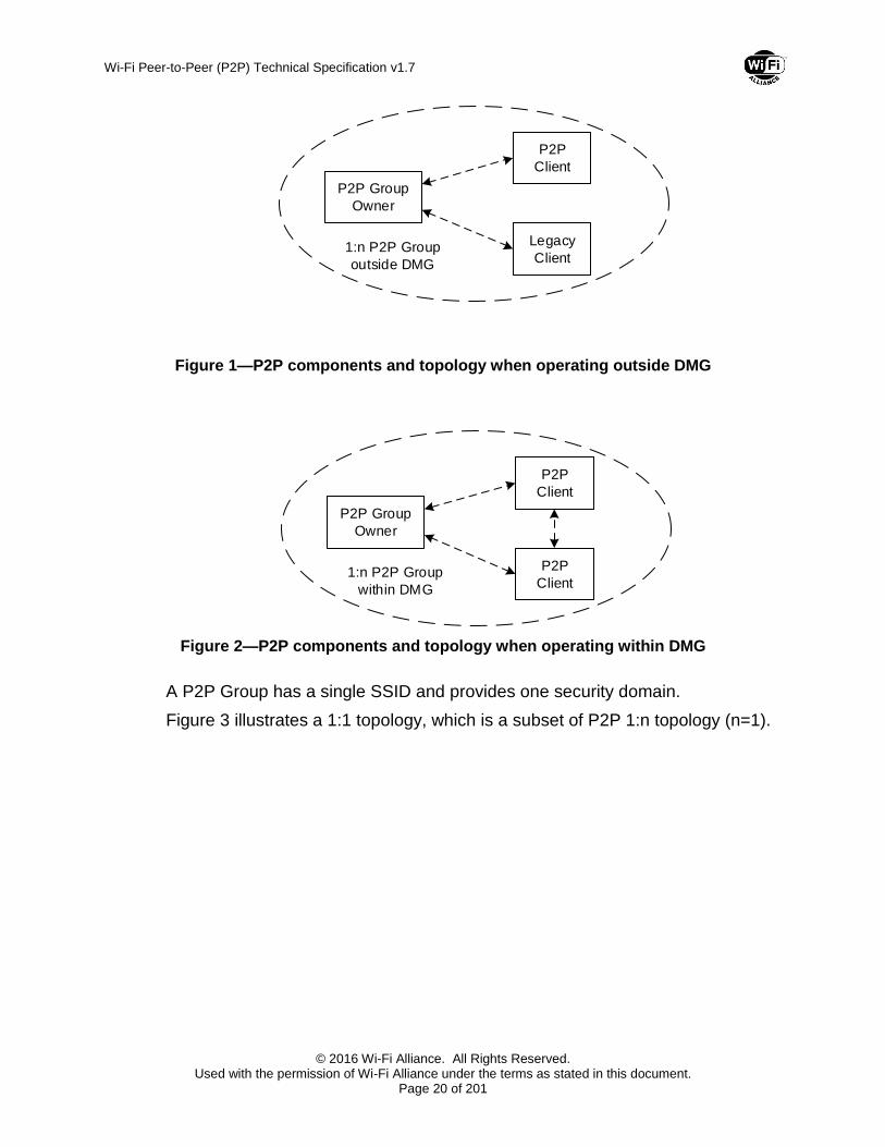
The P2P Topology is 1:n where multiple Clients are connected to one Group Owner. Such a set of connected devices is called a P2P Group. Each Client in a P2P Group operating outside DMG may be either a P2P Client or a Legacy Client, as shown in Figure 1. A P2P Group operating within DMG only includes P2P Clients, as shown in Figure 2.
Wi-Fi Peer-to-Peer (P2P) Technical Specification v1.7
© 2016 Wi-Fi Alliance. All Rights Reserved. Used with the permission of Wi-Fi Alliance under the terms as stated in this document.
Page 20 of 201
P2P Group
Owner
P2P
Client
1:n P2P Group
outside DMG
Legacy
Client
Figure 1—P2P components and topology when operating outside DMG
P2P Group
Owner
P2P
Client
1:n P2P Group
within DMG
P2P
Client
Figure 2—P2P components and topology when operating within DMG
A P2P Group has a single SSID and provides one security domain.
Figure 3 illustrates a 1:1 topology, which is a subset of P2P 1:n topology (n=1).

Wi-Fi Peer-to-Peer (P2P) Technical Specification v1.7
© 2016 Wi-Fi Alliance. All Rights Reserved. Used with the permission of Wi-Fi Alliance under the terms as stated in this document.
Page 21 of 201
Figure 3—A subset of P2P 1:n topology (n=1)
2.3 Concurrent operation
A P2P Device can operate concurrently with a WLAN (infrastructure network). Such a device is considered a P2P Concurrent Device. The concurrent operation requires a device to support multiple MAC entities.
Figure 4—P2P Concurrent device
As an example, Figure 4 shows a P2P Concurrent Device that has one MAC entity operating as a WLAN-STA and the second MAC entity operating as a P2P Device. The dual MAC functionality can be provided via two separate physical MAC entities each associated with its own PHY entity, two virtual MAC entities over one PHY entity, or any other approach. Implementation of multiple MAC functionality is out of scope of this specification.
A P2P Group may operate in the same or different operating class and channel as a concurrently operating WLAN BSS. For example, a WLAN BSS may
Wi-Fi Peer-to-Peer (P2P) Technical Specification v1.7
© 2016 Wi-Fi Alliance. All Rights Reserved. Used with the permission of Wi-Fi Alliance under the terms as stated in this document.
Page 22 of 201
operate in channel 36 in the 5.2 GHz band, while the P2P Group may operate in channel 6 in the 2.4 GHz band or in channel 2 in the 60 GHz band within DMG.
This specification does not preclude a P2P Device operating as a member of more than one P2P Group simultaneously, however, such operation is out of scope and therefore not described.
2.4 Functions and services
2.4.1 Basic functions and services
For P2P operation outside the DMG, this specification assumes that the following STA functions and services are implemented in P2P Devices:
IEEE 802.11g or newer 2.4 GHz PHY [1]
IEEE 802.11i (AES-CCMP) [1]
Wi-Fi Simple Configuration [2]
Wi-Fi Multimedia [3]
For P2P operation within DMG, this specification assumes that the following STA functions and services are implemented in P2P Devices:
DMG operation as defined in IEEE 802.11-REVmc [11]
AES-GCMP as defined in IEEE 802.11-REVmc [11]
Wi-Fi Simple Configuration [2]
Any required ‘AP-like’ functions and services required for P2P Group Owner operation outside DMG are described within this specification. A P2P Group Owner operating within DMG is required to support PCP functions and services.
In order to promote efficient wireless medium use when operating outside DMG:
P2P Devices shall not use 11b rates (1, 2, 5.5, 11 Mbps) for data and management frames except:
Probe Request frames sent to both P2P Devices and non-P2P Devices.
P2P Devices shall not respond to Probe Request frames that indicate support for 11b rates only.
Note 1 —This means that the P2P Group Owner transmits Beacon frames using OFDM.
Note 2 — This means that the P2P Group Owner transmits Probe Response frames using OFDM, including frames sent in response to Probe Requests received at 11b rates from non 11b-only devices.
Note 3 — P2P Devices shall not include 11b rates in the list of supported rates in Probe Request frame intended only for P2P Devices. 11b rates may be included in the list of supported rates in Probe Request frames intended for both P2P Devices and non-P2P Devices.

Wi-Fi Peer-to-Peer (P2P) Technical Specification v1.7
© 2016 Wi-Fi Alliance. All Rights Reserved. Used with the permission of Wi-Fi Alliance under the terms as stated in this document.
Page 23 of 201
2.4.2 P2P specific functions and services
In addition to the assumed functions listed in Section 2.4.1, a P2P Device supports the following P2P specific functions:
P2P Discovery provides a set of functions to allow a device to easily and quickly identify and connect to another P2P Device and its services in its vicinity.
P2P Group Operation resembles infrastructure BSS operation as defined in IEEE 802.11-2012 [1] when operating outside DMG and PBSS operation as defined in IEEE 802.11-REVmc [11] when operating within DMG, and provides additions for a P2P Group operation.
P2P Power Management provides a set of functions to reduce power consumption of P2P Devices that operate outside DMG.
Managed P2P Device Operation (optional) describes the ability for P2P Devices to operate in an enterprise environment where P2P Devices may be managed by the Information Technology (IT) department of the enterprise.
Note — An informative diagram shown in Appendix A illustrates P2P Device state transitions.
2.4.3 P2P Device addressing
A P2P Device shall have a P2P Device Address, conforming to the format as described in Section 8.2.4.3.2 of IEEE 802.11-2012 [1], which is used to uniquely reference that P2P Device. The P2P Device Address of a P2P Device shall be its globally administered MAC address, or its globally administered MAC address with the locally administered bit set. The P2P Device Address shall be used as the receiver address (RA) for all frames sent to a P2P Device during P2P Discovery, with the sole exception of using a broadcast receiver address in a Probe Request. The P2P Device Address shall be used as the transmitter address (TA) for all frames sent by a P2P Device during P2P Discovery.
A P2P Device will assume the role of P2P Group Owner or P2P Client when in a P2P Group. The P2P Device is a different logical entity from the P2P Client or P2P Group Owner so has its own addressing mechanism. The P2P Device shall assign a P2P Interface Address, corresponding to the format as described in Section 8.2.4.3.2 of IEEE 802.11-2012 [1], which is used to communicate with the P2P Group Owner or Clients within a P2P Group. A P2P Interface Address is not required to be globally unique and may be locally administered. A P2P Interface Address may be the same as the P2P Device Address provided the requirements for P2P Interface Address in this clause are satisfied. A P2P Device shall use its P2P Interface Address as the transmitter address (TA) for all frames sent within a P2P Group. A P2P Device shall use the P2P Interface Address of the intended recipient P2P Device as the receiver address (RA) for all unicast frames sent within a P2P Group.

Wi-Fi Peer-to-Peer (P2P) Technical Specification v1.7
© 2016 Wi-Fi Alliance. All Rights Reserved. Used with the permission of Wi-Fi Alliance under the terms as stated in this document.
Page 24 of 201
A P2P Device shall only use a P2P Interface Address for communication within a P2P Group. All other communication between P2P Devices shall use the P2P Device Address.
A P2P Group has a session that starts and ends as described in Section 3.2 and subsections. A Persistent P2P Group may have multiple distinct sessions. The P2P Interface Address shall be assigned prior to starting a P2P Group session and shall not change within a P2P Group session. The P2P Interface Address expires at the end of a P2P Group session. A P2P Device may use a different P2P Interface Address for distinct sessions of a P2P Group. A P2P Device shall not attempt to communicate to a P2P Device using a P2P Interface Address from a P2P Group session that has ended.
As described in Section 2.3 a P2P Device may support more than one interface for the purpose of a concurrent WLAN connection. A P2P Device shall assign a P2P Interface Address for the P2P Group that is distinct from the address used for the concurrent WLAN connection.
As discussed in Section 2.3 a P2P Device may support more than one interface for the purpose of membership of multiple P2P Groups. A P2P Device shall assign a different P2P Interface Address for each P2P Group for which it is concurrently a member.
The BSSID (Address 3 field value) to be used in frames sent by a P2P Device during the Find Phase and during Group Operation is specified in Section 3.1.2.1.3 and Section 3.2.2. When communication is not within a P2P Group, e.g. during Service Discovery, P2P Invitation, GO Negotiation and Device Discoverability, a P2P Device shall use the P2P Device Address of the intended destination as the BSSID in Request, or Confirmation frames and its own P2P Device Address as the BSSID in Response frames.

Wi-Fi Peer-to-Peer (P2P) Technical Specification v1.7
© 2016 Wi-Fi Alliance. All Rights Reserved. Used with the permission of Wi-Fi Alliance under the terms as stated in this document.
Page 25 of 201
3 Functional description and procedures
3.1 P2P discovery
3.1.1 Introduction
P2P Discovery enables P2P Devices to quickly find each other and form a connection.
P2P Discovery consists of the following major components:
Device Discovery facilitates two P2P Devices arriving on a common channel and exchanging device information (e.g. device name and device type).
Service Discovery is an optional feature that allows a P2P Device to discover available higher-layer services prior to forming a connection.
Group Formation is used to determine which device will be the P2P Group Owner and form a new P2P Group.
P2P Invitation is used to invoke a Persistent P2P Group or invite a P2P Device to join an existing P2P Group.
Note – During P2P Discovery, a DMG STA can ignore P2P public action frames received outside of a beacon interval if it does not know how to respond to such frames.
3.1.2 Device Discovery procedures
3.1.2.1 Basic mechanisms of Device Discovery
The objective of P2P Device Discovery is to find P2P Devices and quickly determine the P2P Device to which a connection will be attempted. In-band P2P Device Discovery consists of two major phases: Scan and Find, which are described in detail in the following sections. Alternatively, if two P2P Devices support NFC, the user may specify the target device by touching the P2P Device’s NFC Interface to the corresponding device’s NFC Interface. Such NFC Out-of-Band Device Discovery is defined in Section 3.1.2.7.
In-band Device Discovery uses Probe Request and Probe Response frames to exchange device information. When operating outside DMG, the P2P Devices in a P2P Group are discovered via a Probe Response frame from the P2P Group Owner. When operating within DMG, P2P Devices in a P2P Group are normally discovered via an SSW frame received in response to a DMG Beacon transmission as described in Section 11.1.4.3 of IEEE 802.11-REVmc [11]; Probe Request and Probe Response frames are subsequently used to exchange device information. Alternatively, Probe Request and Probe Response frames may be used instead of SSW frames for devices that do not use beamforming.

Wi-Fi Peer-to-Peer (P2P) Technical Specification v1.7
© 2016 Wi-Fi Alliance. All Rights Reserved. Used with the permission of Wi-Fi Alliance under the terms as stated in this document.
Page 26 of 201
A P2P Device shall not respond to Probe Request frames unless it is:
a P2P Group Owner or
in the Listen State, or
in the Search State and the P2P Device operates within DMG, or
a P2P Device associated with an infrastructure AP on the channel on which the Probe Request was sent — in which case the P2P Device may respond provided it is not already a member of a P2P Group, or
a P2P Client supporting Peer-to-Peer services (P2Ps) [10], having a Service Advertiser with a Service Hash matching the hash value in the incoming Probe Request, as described in 3.4.3.2 (Advertise Service fields in Probe Response) of [10], on the operating channel of the P2P group that the client connected.
When operating outside DMG, a P2P Device shall not transmit Beacon frames unless it is a P2P Group Owner.
Note 1 — Section 2.4.1 contains additional rules that apply to frames sent during In-band Device Discovery.
Note 2 – When operating within DMG, the requirements for DMG Beacon transmission are described in IEEE 802.11-REVmc [11].
3.1.2.1.1 Listen State
A P2P Device that is not in a P2P Group may use the Listen State to become discoverable. In the Listen State a P2P Device dwells on a given channel, termed the Listen Channel. This is a channel chosen from the list of Social Channels. Channels 1, 6, and 11 in the 2.4 GHz band and channel 2 in the 60 GHz band within DMG shall be used as the Social Channels. The Listen Channel shall be chosen at the beginning of the In-band Device Discovery and shall remain the same until P2P Discovery completes.
As specified in Section 11.1.4.3.3 of IEEE 802.11-REVmc [11], when operating within DMG a P2P Device may perform beamforming with another P2P Device before Probe Request and Probe Response frames can be exchanged between the devices. Therefore, as specified in Section 11.1.4.3.3 of IEEE 802.11-REVmc [11], a P2P Device in Listen State that receives a Discovery DMG Beacon frame performs the procedure specified in Section 10.38.5 of IEEE 802.11-REVmc [11] before exchanging Probe Request and Probe Response frames.
When operating within DMG, a P2P Device in Listen State that responds to a Probe Request or Discovery DMG Beacon frame transmitted by a peer P2P Device may need to initiate beamforming with the peer P2P Device to restore or refine the communication link.
A P2P Device operating within DMG and in Listen State
Shall not transmit any frame before receiving a Probe Request or Discovery DMG Beacon frame from a peer P2P Device.

Wi-Fi Peer-to-Peer (P2P) Technical Specification v1.7
© 2016 Wi-Fi Alliance. All Rights Reserved. Used with the permission of Wi-Fi Alliance under the terms as stated in this document.
Page 27 of 201
Shall only transmit control or management frames sent in response to a management frame from the peer P2P Device.
Shall only transmit control frames to initiate or complete beamforming with the peer P2P Device with the RA field set to the P2P Device Address of the peer P2P Device, for example, Grant, Grant Ack, SSW, SSW-Feedback and SSW-ACK frames. Note that a Peer P2P Device in this case may not be able to respond to a beamforming request until it moves to Listen State or repeats the Scan Phase.
A P2P Device in the Listen State shall only reply to Probe Request frames that contain the P2P IE, the P2P Wildcard SSID element, a Wildcard BSSID, and a Destination Address that is either the broadcast address or its P2P Device Address. If one or more Requested Device Type attributes are present in the WSC IE in the Probe Request frame, the P2P Device in the Listen State shall only respond with a Probe Response frame if it has a Primary Device Type or Secondary Device Type value identical to any of the Requested Device Type values. If a Device ID attribute is present in the P2P IE in the Probe Request frame, the P2P Device in the Listen State shall only respond with a Probe Response frame if its Device Address matches that in the Device Address field in the Device ID attribute.
One or more P2P IEs and the WSC IE shall be inserted after other information elements in the Probe Response frames transmitted by a P2P Device. The inclusion of the WSC IE in the Probe Response frame sent by a P2P Device allows it to advertise human-readable device-specific information. The WSC IE shall contain the required attributes for an AP/Registrar as described in Section 8.2.5 (Probe Response (D-AP/Registrar)) of [2]. Device Password ID shall be a required attribute if Credentials are available and ready for immediate use.
Note — Examples of Credentials being ‘available and ready for immediate use’ include active PBC mode (PBC method), PIN being displayed (Display method) and PIN entered (Keypad method).
A P2P Device in the Listen State shall set the Source Address (SA) and BSSID to its P2P Device Address, and shall set the SSID to the P2P Wildcard SSID in all Probe Response frames that it sends. If the Probe Response is transmitted outside DMG, the P2P Device shall set the ESS bit of the Capabilities field in the Probe Response frame to 0 and IBSS bit to 0. If the Probe Response is transmitted within DMG, the P2P Device shall set the BSS Type subfield of the Capabilities field in the Probe Response frame to 1 (non-PCP/non-AP DMG STA).
The Find Phase, as described in Section 3.1.2.1.30 makes use of the Listen State. The P2P Device in the Find Phase shall stay in the Listen State for the time periods defined in the Find Phase and shall be constantly available within those time periods.
When not in Find Phase, a P2P Device may stay in the Listen State for an extended period of time. Any interruption in availability, for example to scan or use power save mechanisms as defined in IEEE 802.11-2012 [1] when

Wi-Fi Peer-to-Peer (P2P) Technical Specification v1.7
© 2016 Wi-Fi Alliance. All Rights Reserved. Used with the permission of Wi-Fi Alliance under the terms as stated in this document.
Page 28 of 201
operating outside DMG and IEEE 802.11-REVmc [11] when operating within DMG, may result in lengthened or unreliable discovery. A P2P Device should be available in the Listen State for at least a contiguous period of 500ms every 5s in order to enable other P2P Devices to discover it. A P2P Device may support reconnection of a Persistent P2P Group in which case it may need to modify this timing, as described in Section 3.2.5.
3.1.2.1.2 Scan Phase
The Scan Phase uses the scanning process defined in IEEE 802.11-2012 [1] when operating outside DMG and IEEE 802.11-REVmc [11] when operating within DMG. It may be used by a P2P Device to find P2P Devices or P2P Groups and to locate the best potential Operating Channel to establish a P2P Group. In the Scan Phase, devices collect information about surrounding devices or networks by scanning all supported channels.
The P2P Device in the Scan Phase shall not reply to Probe Request frames.
A P2P Device may simultaneously scan for P2P Groups and legacy networks (i.e. 802.11 infrastructure networks). The WSC IE shall be included in all Probe Request frames, with Device Name, Primary Device Type and Device Password ID as required attributes. A P2P Device that uses PushButton configuration method shall indicate when it is in active PBC mode (i.e. during the 120 second walk time after the user has pressed the push button) by setting the Device Password ID value to PushButton. Secondary Device Type List shall be an optional attribute. A P2P Device may send a Probe Request frame containing the P2P IE and the Wildcard SSID to elicit Probe Response frames from both legacy networks and P2P Group Owners. Inclusion of the P2P IE in the Probe Request frame is required to enable the P2P Group Owner to include the P2P Group Info attribute in the Probe Response frame. P2P Clients shall not reply to Probe Request frames so they can only be discovered by the Probe Response frame from the P2P Group Owner containing the P2P Group Info attribute, as described in Section 3.2.4.
A P2P Device may limit its Scan to P2P Devices and Groups. A Probe Request frame intended only for P2P Devices shall include the P2P IE and shall have the SSID element set to the P2P Wildcard SSID.
Note — There is a very low probability of a legacy network that has the P2P Wildcard SSID as its SSID; such a Probe Response frame may be identified by the lack of the P2P IE.
A P2P Device may narrow its scan to either:
a specific device type, or device types by including the WSC IE with one or more Requested Device Type attribute in the Probe Request frame. The Requested Device Type attribute has the same format as the Primary Device Type attribute in the WSC specification [2].
a specific P2P Device by including the P2P Device ID attribute in the P2P IE in the Probe Request frame. This provides a mechanism to scan for a specific P2P Device.

Wi-Fi Peer-to-Peer (P2P) Technical Specification v1.7
© 2016 Wi-Fi Alliance. All Rights Reserved. Used with the permission of Wi-Fi Alliance under the terms as stated in this document.
Page 29 of 201
3.1.2.1.3 Find Phase
The Find Phase is used to ensure that two P2P Devices performing Device Discovery arrive on a common channel to enable communication. This is achieved by cycling between states where the P2P Device waits on a fixed channel for Probe Request or Discovery DMG Beacon frames (the Listen State) or sends Probe Request or Discovery DMG Beacon frames on a fixed list of channels (the Search State). Convergence of two devices on the same channel is assisted by randomizing the time spent in each cycle of the Listen State. Time to converge is minimized by limiting the list of channels to a small set known as the Social Channels. In the Find Phase, a P2P Device shall alternate between the Listen and Search states as specified below.
The duration of each Listen State within the Find Phase shall be a random integer of 100 TU Intervals. This random integer shall be no greater than the maxDiscoverableInterval value and no less than the minDiscoverableInterval value. Default values for maxDiscoverableInterval and minDiscoverableInterval values are 3 and 1 respectively. The randomness in the time spent in the Listen state is to avoid a case where two P2P Devices in the Find Phase are in lock-step and thus will never find each other. While in the Listen State within the Find Phase a P2P Device shall be constantly available on the Listen Channel.
The values for maxDiscoverableInterval and minDiscoverableInterval shall be nonzero.
The duration of each Search State within the Find phase is implementation dependent.
P2P Devices in the Search State shall transmit one or more Probe Request or Discovery DMG Beacon frames on each of the Social Channels supported by the P2P Device. All Probe Request frames transmitted by P2P Devices in the Search State shall:
Include the P2P IE.
Include the WSC IE, with Device Name, Primary Device Type, and Device Password ID as required attributes. Secondary Device Type List shall be an optional attribute. A P2P Device that uses PushButton configuration method shall indicate when it is in active PBC mode (i.e. during the 120 second walk time after the user has pressed the push button) by setting the Device Password ID value to PushButton.
Have the SSID field set to the P2P Wildcard SSID.
Have the BSSID field set to the Wildcard BSSID.
Probe Request frames sent by P2P devices in the Search State may include either one of the following:
Requested Device Type attribute in the WSC IE. This attribute has the same format as the Primary Device Type attribute in the WSC specification.
P2P Device ID attribute in the P2P IE.

Wi-Fi Peer-to-Peer (P2P) Technical Specification v1.7
© 2016 Wi-Fi Alliance. All Rights Reserved. Used with the permission of Wi-Fi Alliance under the terms as stated in this document.
Page 30 of 201
A P2P Device in Search State that transmits a Discovery DMG Beacon frame may reduce the set of P2P Devices that are allowed to respond in the A-BFT following the BTI where the Discovery DMG Beacon frame is transmitted. To achieve this, the P2P Device shall set the CC Present field to 1 in the Discovery DMG Beacon frame and shall set the A-BFT Responder Address subfield to a known P2P Device Address or to a known P2P Group Address (specifically, the P2P Device Address field of the P2P Group ID attribute). When the A-BFT Responder Address subfield identifies a P2P Group Address, all P2P Devices in the group are allowed to respond during the A-BFT following the BTI where the Discovery DMG Beacon frame is transmitted.
When operating outside DMG, a P2P Device in the Search State shall not reply to Probe Request frames. When operating within DMG, a P2P Device in the Search State may reply to Probe Request frames.
As specified in Section 11.33 of IEEE 802.11-REVmc [11], multi-band capable P2P Devices include the Multi-band element as described in IEEE 802.11-REVmc [11] in transmitted Probe Request and Probe Response frames. This allows the multi-band capable P2P Device to signal support to more than one frequency band.
As specified in Section 11.1.4.3.3 of IEEE 802.11-REVmc [11] when operating within DMG, a P2P Device that is in Search State might have to perform the active scanning procedure described in Section 11.1.3.4 of IEEE 802.11-REVmc [11] prior to transmitting Probe Request or Probe Response frames on a channel. Once the P2P Device successfully establishes a beamforming link, the P2P Device transmits Probe Request or Probe Response frames. The P2P Device that performs the procedure described in Section 11.1.3.4 of IEEE 802.11-REVmc [11] shall set the BSS Type field within the transmitted DMG Beacon and Probe Response frames to 1 (non-PCP/non-AP DMG STA).
Note – When operating within DMG, a P2P Device that is in Search State can increase the chances of discovering another P2P Device by staying awake longer following the A-BFT.
In-band Device Discovery procedures of a P2P Device operating outside DMG are illustrated in Figure 5. In-band Device Discovery procedures of a P2P Device operating within DMG are illustrated in Figure 6.

Wi-Fi Peer-to-Peer (P2P) Technical Specification v1.7
© 2016 Wi-Fi Alliance. All Rights Reserved. Used with the permission of Wi-Fi Alliance under the terms as stated in this document.
Page 31 of 201
Figure 5—Example In-band Device Discovery procedures for a P2P Device operating outside DMG

Wi-Fi Peer-to-Peer (P2P) Technical Specification v1.7
© 2016 Wi-Fi Alliance. All Rights Reserved. Used with the permission of Wi-Fi Alliance under the terms as stated in this document.
Page 32 of 201
Probe Request (P2P IE, WSC IE)
P2P Device 1 P2P Device 2
scan
listen
listen
Discover other
P2P Devices
Optional WSC
Provisioning Command
802.11 Scan
with in DMG
search
scan
ch
2
10
0T
U
ch
2
listen
100
TU
10
0T
U
ch
2
ch 2 Scan on all
channels
Legend
Probe Response (P2P IE, WSC IE, RSN IE)
802.11 Scan
with in DMG
Discover other
P2P Devices
Optional WSC
Provisioning Command
Notify that P2P
Device found
SME/Application/
User/Vendor 1 SME/Application/
User/Vendor 2
Listen State for N
intervals o f 100TUs.
N is random.
DMG Beamforming (optional)
Notes:1) Probe Response may be sent in
Search State.2) P2P Devices in the Search State
shall transmit one or more Probe Requests or Discovery DMG Beacons on the Social Channel.
Figure 6—Example In-band Device Discovery procedures for a P2P Device operating within DMG
If a P2P Device operating within DMG successfully completes Device Discovery with a peer P2P Device and decides to proceed with establishing a P2P connection with the peer P2P Device, then all Discovery DMG Beacon frames transmitted following Device Discovery should have the CC Present field equal to 1 and the A-BFT Responder Address field set to the P2P Device Address of the peer P2P Device. This serves to limit the number of P2P Devices that respond in the following A-BFT.
3.1.2.2 P2P Device discovering a P2P Device that is in a P2P Group
A searching P2P Device discovers a P2P Group Owner in the Scan Phase through received Beacon, DMG Beacon, SSW, or Probe Response frames. The searching P2P Device will also discover other P2P Devices that are associated to that P2P Group Owner from Group Information Advertisement (see Section 3.2.4) or, when operating within DMG, through a STA Availability element or Information Response frame (see Section 11.30.1 of IEEE 802.11-REVmc [11]).
A searching P2P Device operating outside DMG should be aware that the P2P Group Owner may use P2P power saving and this may impact discoverability of the P2P Group (see Section 3.3.2). A searching P2P Device operating within DMG should be aware that the P2P Group Owner may use power saving as specified in Section 11.2.6.3 of IEEE 802.11-REVmc [11] and this may impact discoverability of the P2P Group (see Section 3.3.2).

Wi-Fi Peer-to-Peer (P2P) Technical Specification v1.7
© 2016 Wi-Fi Alliance. All Rights Reserved. Used with the permission of Wi-Fi Alliance under the terms as stated in this document.
Page 33 of 201
A searching P2P Device operating outside DMG should be aware that the target P2P Device may use P2P power saving and this may impact communication with the P2P Device. A searching P2P Device operating within DMG should be aware that the target P2P Device may use power saving as specified in Section 11.2.6.2 of IEEE 802.11-REVmc [11] and this may impact communication with the P2P Device.
If the target P2P Device is a P2P Client in a P2P Group, a searching P2P Device may send a Device Discoverability Request frame to the P2P Group Owner with the P2P Device ID of the target P2P Device. The P2P Group Owner indicates to the target P2P Device the request to be available for discovery and sends a Device Discoverability Response, as described in Section 3.2.4. If the target P2P Device is making use of power save mechanisms this response may take multiple beacon periods. On reception of a Device Discoverability Response frame that indicates success in the status code the searching P2P Device may attempt to perform Service Discovery or establish a P2P Group with the target P2P Device.
In addition, when operating within DMG, a searching P2P Device may discover the presence or absence of other P2P Clients in the P2P Group by sending an Information Request frame to the P2P Group Owner to solicit an Information Response frame as specified in Section 11.30 of IEEE 802.11-REVmc [11]. In the transmitted Information Request frame, the searching P2P Device may also request to obtain the wakeup schedule of the target P2P Client. The wakeup schedule includes the periods of time when the target P2P Client is awake, and hence when Device Discovery or Service Discovery with the target P2P Client can be successful.
A P2P Client may indicate to the P2P Group Owner that it does not currently support P2P Discovery as described in Section 3.2.4.
Information in the P2P Capability attribute may be used to decide whether to attempt to join a P2P Group. If the P2P Group Limit field indicates that more connections are supported then the P2P Device may attempt to join the P2P Group to connect to the P2P Group Owner. If the Intra-BSS Distribution field indicates that communication between P2P Clients is supported then the searching P2P Device may join the P2P Group to communicate with any of the P2P Devices in the P2P Group.
When operating within DMG, the P2P Group Owner shall operate as PCP of the underlying PBSS.
If a P2P Device operating within DMG performs in the role of P2P Group Owner, the P2P Device shall set the P2P Group Owner field within the P2P Capability attribute to 1. Otherwise, this field shall be set to 0.
If a P2P Device desires to join a P2P Group it may do one of the following:
Use Wi-Fi Simple Configuration [2] to obtain Credentials. Wi-Fi Simple Configuration will take place on the Operating Channel of the P2P Group Owner.

Wi-Fi Peer-to-Peer (P2P) Technical Specification v1.7
© 2016 Wi-Fi Alliance. All Rights Reserved. Used with the permission of Wi-Fi Alliance under the terms as stated in this document.
Page 34 of 201
If the P2P Device is provisioned, connect to the P2P Group as described in Section 3.2.3.
If a searching P2P Device does not want to join the P2P Group that the discovered P2P Device is a member of, the searching P2P Device may do one of the following:
Send a P2P Invitation Request frame to request that the target P2P Device joins a P2P Group of which the searching P2P Device is the P2P Group Owner or a P2P Client.
Send a P2P Invitation Request frame to request that a previously established Persistent P2P Group, of which one of the P2P Devices is the P2P Group Owner, be invoked (see Section 3.1.5).
Subject to the rules in Section 3.1.4, initiate Group Owner Negotiation to attempt to form a new P2P Group. The P2P Device Limit field bit in the Device Capability Bitmap field of the P2P Capability attribute indicates if the target P2P Device is able to establish an additional P2P connection.
.
3.1.2.3 Two P2P Devices in discovery
A P2P Device in the Scan Phase may discover a P2P Device in the Listen State. The Find Phase is used to ensure that two P2P Devices that are both in In-band Device Discovery arrive on a common channel to exchange device information. If a P2P Device wishes to connect it may do one of the following:
Initiate Group Owner Negotiation to attempt to form a new P2P Group.
Send a P2P Invitation Request frame to request that a previously established Persistent P2P Group, of which one of the P2P Devices is the P2P Group Owner, be invoked (see Section 3.1.5).
Send a P2P Invitation Request frame to request that the target P2P Device joins a P2P Group of which the searching P2P Device is the P2P Group Owner or a P2P Client. In-band
3.1.2.4 Device Discovery procedures for a P2P Group Owner
A P2P Device that is already operating as a P2P Group Owner stays on the Operating Channel and waits for other devices to discover it. A P2P Group Owner may search on other channels to find desired devices or services.
When operating outside DMG, if the P2P Group Owner is unavailable on the Operating Channel it shall indicate this using the Notice of Absence mechanism as defined in Section 3.3.3.2. When operating within DMG, if a P2P Group Owner is unavailable on the Operating Channel it shall indicate this using the mechanism described in Section 11.2.6.3 of IEEE 802.11-REVmc [11] .
3.1.2.5 P2P Group Owner enabling discovery for a Legacy Client
The procedures in this Section apply only to operation outside DMG.

Wi-Fi Peer-to-Peer (P2P) Technical Specification v1.7
© 2016 Wi-Fi Alliance. All Rights Reserved. Used with the permission of Wi-Fi Alliance under the terms as stated in this document.
Page 35 of 201
A Legacy Client uses the 802.11 scan process as defined in IEEE 802.11-2012 [1] to collect information about surrounding devices or networks. A Legacy Client can only discover a P2P Group Owner. When a P2P Group Owner receives a Probe Request frame from a Legacy Client in its Operating Channel, the P2P Device shall transmit a Probe Response frame as defined in IEEE 802.11-2012 [1] except as noted in Section 2.4.1. The Legacy Client may use the collected information to initiate Wi-Fi Simple Configuration [2] in order to connect to the P2P Device.
A Legacy Client that does not support Wi-Fi Simple Configuration [2] has to be provisioned using methods outside the scope of this specification. The P2P Group Owner shall generate the Credentials used for provisioning.
3.1.2.6 P2P Device discovering a P2P Device associated with an infrastructure AP
A searching P2P Device may discover a P2P Device associated with an infrastructure AP in the Scan Phase through Probe Response frames. A P2P Device associated with an infrastructure AP receiving a Probe Request frame with a P2P IE and either a wildcard SSID or a P2P wildcard SSID may respond with a Probe Response frame with a P2P IE. A searching P2P Device should be aware that the P2P Device may use power saving and this may impact its discoverability (see Section 3.1.2.2). A P2P Device that is associated with an infrastructure AP shall still need to be in the Listen State for In-band Device Discovery as described in Section 3.1.2.1.1 and Section 3.1.2.1.3.
Information in the P2P Capability attribute, or a Service Discovery exchange may be used to decide whether to attempt to establish a P2P Group as described in Section 3.1.2.2.
If a P2P Device desires to communicate with the discovered device it may do one of the following on the channel of the discovered P2P Device:
Send a P2P Invitation Request frame to request that the target P2P Device joins a P2P Group of which the searching P2P Device is the P2P Group Owner or a P2P Client.
Send a P2P Invitation Request frame to request that a previously established Persistent P2P Group, of which one of the P2P Devices is the P2P Group Owner, be invoked (see Section 3.1.5).
Subject to the rules in Section 3.1.4, initiate Group Owner Negotiation to attempt to form a new P2P Group. The P2P Device Limit field bit in the Device Capability Bitmap field of the P2P Capability attribute indicates if the target P2P Device is able to establish an additional P2P connection.
3.1.2.7 Out-of-Band Device Discovery using NFC
If a user recognizes that both of two P2P Devices support NFC, then the user may initiate NFC Out-of-Band channel for Device Discovery. The NFC Out-of-Band Device Discovery is used to ensure that two P2P Devices:
Agree on a common channel for GO negotiation for the Group Formation if no suitable group exists.

Wi-Fi Peer-to-Peer (P2P) Technical Specification v1.7
© 2016 Wi-Fi Alliance. All Rights Reserved. Used with the permission of Wi-Fi Alliance under the terms as stated in this document.
Page 36 of 201
Exchange WSC and P2P attributes to allow the devices to form a new group or allow one of the devices to join an existing group.
If using NFC Out-of-Band communication, then a P2P Device or P2P Group Owner shall use NFC Handover Request/Select Message for Out-of-Band Device Discovery. NFC Handover Request/Select Messages are exchanged over the Out-of-Band channel before the Group Formation or P2P Invitation.
Figure 7 shows the example of NFC Out-of-Band Device Discovery using NFC Negotiated Handover between two P2P Devices with NFC Interface.
P2P Device 1 P2P Device 2
Bring the P2P Device into close
proximity and tap the UI
Device Discovery
(Out-of-Band)
Handover Request
(WSC Attributes, P2P Attributes)
Handover Select
(WSC Attributes, P2P Attributes)
UserNFC I/FWi-Fi NFC I/F Wi-Fi
Device Discovery
(Out-of-Band)
Bring the P2P Device into
close proximity
Device Found
Figure 7—Out-of-Band Device Discovery (NFC Negotiated Handover)
When two P2P Devices which have an NFC Interface are brought into close proximity, they will establish NFC communication based on the NFC Forum Logical Link Control Protocol (LLCP) specification [9]. If one of the devices has intention to activate a further Wi-Fi communication method, it may then use the NFC Forum Connection Handover protocol to announce possible communication means and request the other device to respond with a selection of matching technologies, including necessary WSC and P2P attributes.
When a P2P Device has established NFC-LLCP communication with another P2P Device, it sends a Handover Request Message as described in [9]. Note that in some circumstances both P2P devices may send a Handover Request Message simultaneously, in which case the collision is handled by the Connection Handover protocol as described in [9]. The corresponding P2P Device shall respond to a Handover Request Message with a Handover Select Message.
The Handover Request/Select Messages:
If the sender is a client of a P2P Group, the Handover Request/Select Messages shall include P2P attributes and shall omit the mandatory WSC attributes of the sender in the Wi-Fi P2P Carrier Configuration Record which is defined in Section 4.5.1 or 4.5.2 . Otherwise, both P2P and WSC attributes shall be included in the Wi-Fi P2P Carrier Configuration Record.
Shall include the Out-of-Band Group Owner Negotiation Channel attribute where

Wi-Fi Peer-to-Peer (P2P) Technical Specification v1.7
© 2016 Wi-Fi Alliance. All Rights Reserved. Used with the permission of Wi-Fi Alliance under the terms as stated in this document.
Page 37 of 201
If the device is a GO or client of a P2P Group, the channel information shall be set to the P2P Group’s operating channel.
If the device is a P2P Device, it shall be set to the device’s listen channel.
The Role Indication shall be set as described in 4.1.21.
After completion of NFC Out-of-Band Device Discovery, the two P2P devices shall complete the in-band procedure using one of the following:
If both P2P devices are not part of a P2P Group, the device that receives the Handover Select Message shall initiate a suitable in-band procedure using the P2P Device Address indicated in the P2P Device Info attribute and the channel indicated in the Out-of-Band Group Owner Negotiation Channel attribute in the Handover Select Message.
If one P2P device is not part of a P2P Group, and the other is a GO of a P2P Group, the device that is not part of a P2P Group shall start the procedure to join the P2P Group using the P2P Device Address indicated in the P2P Device Info attribute and the channel indicated in the Out-of-Band Group Owner Negotiation Channel attribute contained in either the Handover Request Message or the Handover Select Message sent by the GO. Provision Discovery is not used after NFC Out-of-Band Device Discovery in this case.
If the P2P Device receiving the Handover Request Message is already a P2P client of an existing P2P Group, as indicated by the Role indication in the Out-of-Band Group Owner Negotiation Channel attribute, then it responds with a P2P Handover Select Message as described in [9] containing the Group Owner’s P2P Group ID and Operating Channel attributes, so that the requesting P2P device can find the Group Owner and join the group using a suitable in-band procedure. The mandatory WSC attributes belonging to the P2P device receiving the Handover Request Message shall be omitted in the Handover Select Message; optional WSC attributes may be included to assist with discovering the Group Owner. Whether the NFC Handover Requester chooses to join is left to implementation. However, for better user experience, it should provide an appropriate indication to the user. A P2P Client may be capable of concurrent operation in an Infrastructure BSS and is also able to handle Alternative Carrier for Wi-Fi Simple Configuration [2], in which case it should follow the rules specified therein. See Section 4.4 for more details on how to handle multiple Alternative Carriers.
Figure 8 shows NFC Out-of-Band Device Discovery using NFC Static Handover between the P2P Device with NFC Tag and the P2P Device which supports NFC Interface. Provision Discovery is not used after NFC Out-of-Band Device Discovery in this case.

Wi-Fi Peer-to-Peer (P2P) Technical Specification v1.7
© 2016 Wi-Fi Alliance. All Rights Reserved. Used with the permission of Wi-Fi Alliance under the terms as stated in this document.
Page 38 of 201
P2P Device 1 P2P Device 2
Bring the P2P Device into close
proximity
Device Discovery
(Out-of-Band)
User UserNFC TagWi-Fi NFC I/F Wi-Fi
Device Discovery
(Out-of-Band)
Bring the P2P Device into
close proximity
Device FoundHandover Select
(WSC Attributes, P2P Attributes)
Figure 8—Out-of-Band Device Discovery (NFC Static Handover)
If an NFC Static Handover occurs between a P2P Device with NFC Tag and the P2P Device which supports NFC Interface, NFC Interface shall read the Handover Select Message from the NFC Tag.
The Handover Request/Select Message format and its NDEF record for NFC Out-of-Band Device Discovery is defined in Section 4.5. If the P2P Device uses an NFC Tag, its data capacity shall be large enough to store the Handover Select Message defined in 4.5.2.
Whether the NFC Handover Requester chooses to join is left to implementation. However, for better user experience, it should provide an appropriate indication to the user.
It is recommended that NFC enabled P2P devices should remain discoverable over WLAN to maintain interoperability with devices that do not have the NFC option.
3.1.3 Service Discovery procedures
The Service Discovery procedure is an optional frame exchange that may be performed at any time to any discovered P2P Device, for example following a successful Device Discovery procedure prior to group formation. This procedure can be used to determine compatibility information on the services offered by a P2P Device. This protocol is extensible and flexible so that it enables different higher layer service advertisement protocol types such as Bonjour [4] and UPnP [5].
The Service Discovery procedure leverages the Generic Advertisement Service (GAS) protocol/frame exchange as defined in IEEE 802.11-2012 [1]. The Service Discovery procedure uses GAS with unicast standard public action frames with a vendor specific body. It may be a single or multiple GAS Initial Request and Response action frame exchange. The requesting P2P Device transmits one or more GAS Initial Request frames. A target P2P Device that supports Service Discovery responds with one or more GAS Initial Response frames. It is assumed that service information is readily available within a P2P Device supporting Service Discovery and the GAS Initial Response frame shall be returned without delay after receiving a GAS Initial Request.
The Service Discovery procedure can be used to find:

Wi-Fi Peer-to-Peer (P2P) Technical Specification v1.7
© 2016 Wi-Fi Alliance. All Rights Reserved. Used with the permission of Wi-Fi Alliance under the terms as stated in this document.
Page 39 of 201
A list of all services offered by a P2P Device
Information about a single service offered by a P2P Device
Information about multiple services offered by a P2P Device
If there has been a change in the services offered by a P2P Device
The requested information can be for a single service protocol type, for multiple service protocol types, or for all service protocol types supported by a P2P Device.
The requested information can be associated with the frequency band where the Service Discovery procedure is initiated or with any other frequency band supported by a P2P Device. When the requested information corresponds to a frequency band different than the frequency band where Service Discovery is initiated, one of those frequency bands shall be DMG.
The decision to perform Service Discovery is implementation specific and beyond the scope of this specification.
3.1.3.1 Service Discovery Query
The Service Discovery Query frame uses the GAS Initial Request frame as defined in IEEE 802.11-2012 [1].
The Service Discovery Query frame shall support different query types, which changes the content of the fields in the Vendor-Specific content field.
To request a list of all services of all higher layer (above Layer 2) service protocol types, the Service Discovery Query frame shall include a single Service Request TLV with the Service Protocol Type field equal to 0 and a Query Data length of 0. A Service Transaction ID is included in all Service Request and Response TLVs and is used to match the response to the query.
To request a list of all services of a specific higher layer service protocol type, the Service Discovery Query frame shall include a single Service Request TLV with the Service Protocol Type field set to one of the non-zero values defined in Table 78 and a Query Data length of 0.
To request information about a specific service of a specific higher layer service protocol type, the Service Discovery Query frame shall include a single Service Request TLV with the Service Protocol Type field set to one of the non-zero values defined in Table 78 and the Query Data. The Query Data field shall include the service information type pertaining to the requested Service Protocol Type. The service information type is out of scope of this specification since it is defined by the service protocol being used.
To request information about multiple services of a single or multiple higher layer service protocol types, the Service Discovery Query frame shall include multiple Service Request TLVs. Each Service Request TLV shall contain the Service Protocol Type field set to one of the non-zero values defined in Table 78 and the Query Data. The Query Data field shall include the service information type pertaining to the requested Service Protocol Type.

Wi-Fi Peer-to-Peer (P2P) Technical Specification v1.7
© 2016 Wi-Fi Alliance. All Rights Reserved. Used with the permission of Wi-Fi Alliance under the terms as stated in this document.
Page 40 of 201
The Service Update Indicator shall be included in all Service Discovery Query frames. It shall be incremented every time a change occurs in the service information of the P2P Device sending this Service Discovery Query. This allows for a P2P Device to cache service information retrieved from another P2P Device, together with the Service Update Indicator. Whenever a P2P Device notices that the Service Update Indicator for another P2P Device has incremented, it shall know to flush the cached service information for that P2P Device.
To request information about services available in a frequency band other than the frequency band used to transmit the Service Discovery Query frame, the Service Discovery Query frame shall include a Multi-band element as specified in IEEE 802.11-REVmc [11].
3.1.3.2 Service Discovery Response
The Service Discovery Response frame uses the GAS Initial Response frame as defined in IEEE 802.11-2012 [1].
Since the Service Discovery Response frame supports different query types, the Vendor-specific content may contain different fields. A Service Transaction ID is included in all Service Request and Response TLVs and is used to match the response to the query.
If the Service Discovery Query frame is for all services and all higher layer service protocol types, the Service Discovery Response frame may contain multiple Service Response TLVs. Each Service Response TLV shall contain the Service Protocol Type (for example, Bonjour, UPnP, etc.) field set to one of the non-zero values defined in Table 78. The Service Transaction ID is set to the value corresponding to the Service Transaction ID in the Service Request TLV. The Status Code field of each returned Service TLV is set to Service available (value 0 in Table 80). The available service information is contained in the Response Data field. The Response Data field shall contain the service information type and service data pertaining to the Service Protocol Type. If no services are available, a single Service Response TLV is returned with the Service Protocol Type field equal to 0, the Status Code field set to an appropriate error code, and a null value (zero length string) in the Response Data field.
If the Service Discovery Query frame is for all services of a specific higher layer service protocol type, the Service Discovery Response frame may contain multiple Service Response TLVs. Each Service Response TLV shall contain the Service Protocol Type field set to the requested service protocol type. The Service Transaction ID is set to the value corresponding to the Service Transaction ID in the Service Request TLV. The Status Code field of each returned Service TLV is set to Service available (value 0 in Table 80). The Response Data field shall contain the service information type and service data of the available service. If no services are available, a single Service Response TLV is returned with the Service Protocol Type field equal to the requested
Wi-Fi Peer-to-Peer (P2P) Technical Specification v1.7
© 2016 Wi-Fi Alliance. All Rights Reserved. Used with the permission of Wi-Fi Alliance under the terms as stated in this document.
Page 41 of 201
protocol, the Status Code field set to an appropriate error code, and a null value (zero length string) in the Response Data field.
If the Service Discovery Query frame is for a single service of a specific higher layer protocol type, the Service Discovery Response frame shall contain a single Service Response TLV. The Service Response TLV shall contain the Service Protocol Type field set to the requested service protocol type. The Service Transaction ID is set to the value corresponding to the Service Transaction ID in the Service Request TLV. If the service is available the Status Code field is set to Service available (value 0 in Table 80) and the Response Data field contains the corresponding service information type and service data. If the service is not available the Status Code field is set to the appropriate error status value in Table 80 and the Response Data field is a null value (zero length string)..
If the Service Discovery Query frame contains multiple Service Request TLVs for multiple higher layer services and for one or more service protocol types, the Service Discovery Response frame shall contain multiple Service Response TLVs. At least one Service Response TLV will be returned for each corresponding Service Request TLV identified by the Service Transaction ID. Each Service Response TLV shall contain the Service Protocol Type field set to one of the non-zero values defined in Table 78 corresponding to the requested Service Protocol Type. The Service Transaction ID is set to the value corresponding to the Service Transaction ID in the Service Request TLV. If the service is available the Status Code field is set to Service Available (value 0 in Table 80) and the Response Data field contains the corresponding requested service information type and service data. If the service is not available the Status Code field is set to the appropriate error status value in Table 80 and the Response Data field is a null value (zero length string).
The Service Update Indicator shall be included in all Service Discovery Response frames. It shall be incremented every time a change occurs in the Service Information of the P2P Device sending this Service Discovery Response. This allows for a P2P Device to cache service information retrieved from another P2P Device, together with the Service Update Indicator. Whenever a P2P Device notices that the Service Update Indicator for another P2P Device has incremented, it shall know to flush the cached service information for that P2P Device.
If the Service Discovery Query frame included a Multi-band element, the Service Discovery Response may include a Multi-band element as specified in IEEE 802.11-REVmc [11]. If included, the information specified in the Multi-band element transmitted in the Service Discovery Response frame shall correspond to the frequency band specified in the Multi-band element contained in the Service Discovery Query frame.
If the Service Discovery Response frame, with multiple Service Response TLVs, exceeds the GAS Initial Response packet size, then the rules for GAS Fragmentation using GAS Comeback Request and Response shall be used as

Wi-Fi Peer-to-Peer (P2P) Technical Specification v1.7
© 2016 Wi-Fi Alliance. All Rights Reserved. Used with the permission of Wi-Fi Alliance under the terms as stated in this document.
Page 42 of 201
defined in IEEE 802.11-2012 [1]. Appendix C.3 provides information on the GAS Fragmentation frames and procedure.
Figure 9 illustrates an example of the exchange of Service Discovery Query and Response frames for Service Discovery when operating outside DMG. Figure 10 illustrates an example of the exchange of Service Discovery Query and Response frames for Service Discovery when operating within DMG.
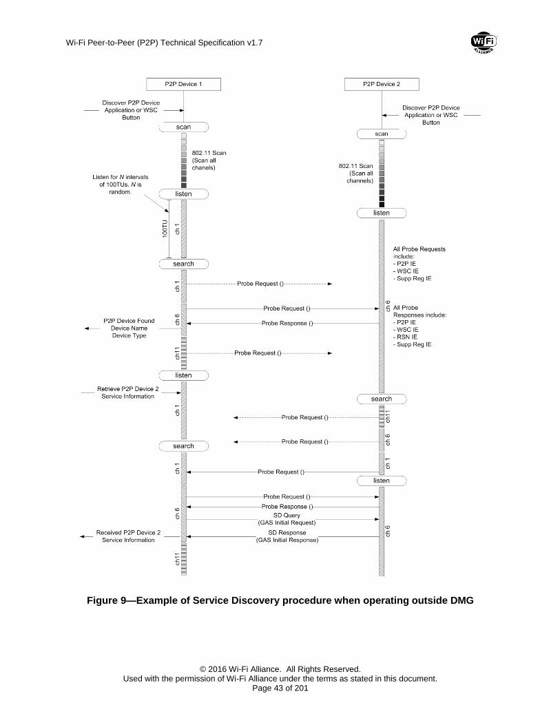
Wi-Fi Peer-to-Peer (P2P) Technical Specification v1.7
© 2016 Wi-Fi Alliance. All Rights Reserved. Used with the permission of Wi-Fi Alliance under the terms as stated in this document.
Page 43 of 201
Figure 9—Example of Service Discovery procedure when operating outside DMG
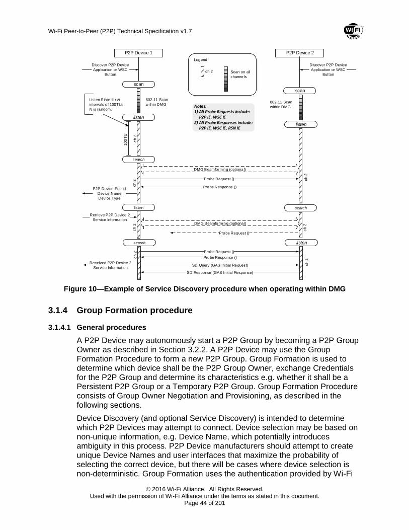
Wi-Fi Peer-to-Peer (P2P) Technical Specification v1.7
© 2016 Wi-Fi Alliance. All Rights Reserved. Used with the permission of Wi-Fi Alliance under the terms as stated in this document.
Page 44 of 201
Probe Request ()
P2P Device 1 P2P Device 2
scan
listen
listen
Discover P2P Device
Application or WSC
Button
802.11 Scan
with in DMG
search
scan
ch 2
100
TU
ch 2
listen
ch
2
ch 2 Scan on all
channels
Legend
Probe Response ()
802.11 Scan
with in DMG
P2P Device Found
Device Name
Device Type
Listen State for N
intervals o f 100TUs.
N is random.
DMG Beamforming (optiona l)
Discover P2P Device
Application or WSC
Button
Notes:1) All Probe Requests include:
P2P IE, WSC IE2) All Probe Responses include:
P2P IE, WSC IE, RSN IE
search
ch 2
Retrieve P2P Device 2
Service Information
Probe Request ()
Probe Request ()
ch 2
Probe Response ()
SD Query (GAS Initial Request)Received P2P Device 2
Service Information
search
ch 2
listen
ch 2
SD Response (GAS Initial Response)
DMG Beamforming (optional)
Figure 10—Example of Service Discovery procedure when operating within DMG
3.1.4 Group Formation procedure
3.1.4.1 General procedures
A P2P Device may autonomously start a P2P Group by becoming a P2P Group Owner as described in Section 3.2.2. A P2P Device may use the Group Formation Procedure to form a new P2P Group. Group Formation is used to determine which device shall be the P2P Group Owner, exchange Credentials for the P2P Group and determine its characteristics e.g. whether it shall be a Persistent P2P Group or a Temporary P2P Group. Group Formation Procedure consists of Group Owner Negotiation and Provisioning, as described in the following sections.
Device Discovery (and optional Service Discovery) is intended to determine which P2P Devices may attempt to connect. Device selection may be based on non-unique information, e.g. Device Name, which potentially introduces ambiguity in this process. P2P Device manufacturers should attempt to create unique Device Names and user interfaces that maximize the probability of selecting the correct device, but there will be cases where device selection is non-deterministic. Group Formation uses the authentication provided by Wi-Fi

Wi-Fi Peer-to-Peer (P2P) Technical Specification v1.7
© 2016 Wi-Fi Alliance. All Rights Reserved. Used with the permission of Wi-Fi Alliance under the terms as stated in this document.
Page 45 of 201
Simple Configuration [2] to determine that the correct devices are connected. Group Formation may need to be executed more than once with different P2P devices to resolve the case of multiple devices with the same Device Name.
Group Formation has a phase called Provisioning that uses Wi-Fi Simple Configuration [2] with constraints as described in Section 3.1.4.3. Wi-Fi Simple Configuration may take up to two minutes to complete, due to waiting for user input. Since Group Formation may need to execute multiple times, such a delay is unacceptable. A P2P Device shall obtain any information required to execute Provisioning in advance of Group Formation, which includes information such as a PIN that is obtained from a user. A P2P Device shall take no more than fifteen seconds to complete Group Formation.
The P2P Device may use the information supplied in the WSC Config Methods attribute, received in a Probe Response, to determine the appropriate information to retrieve from the user e.g. PIN from a display, etc. A P2P Device may send a Provision Discovery Request with a single method set in the Config Methods attribute with the purpose of triggering some required action at the receiving P2P Device e.g. on reception of this frame a display device may display the required PIN. The Provision Discovery Request frame shall have a single method set in the Config Methods attribute to indicate which of the receiving P2P Device’s methods the sending P2P Device intends to use. For example, it shall set the ‘Display’ method if it intends to use a PIN the receiver shall display. A P2P Device shall respond to a received Provision Discovery Request frame with a Provision Discovery Response frame. The Config Methods attribute in the Provision Discovery Response frame may have the same single method set as in the received Provision Discovery Request frame to indicate success or shall be null to indicate failure.
Table 1 summarizes the valid WSC Config Methods attribute settings in the Provision Discovery exchange and the ‘matching’ WSC Device Password ID attribute values to be used in Provisioning.
The P2P Group Owner is always the WSC Registrar and the selected PIN (from the display of either the P2P Client or P2P Group Owner) is indicated using Device Password ID attribute in the WSC M1/M2 messages as shown in Table 1.
Note —In contrast, it is common in non-P2P WSC use that the AP PIN is used with reversed Registrar/Enrollee roles, i.e., a STA connecting to the AP acts as a Registrar and uses the AP PIN (which is the Enrollee Device Password in this reversed-role case).
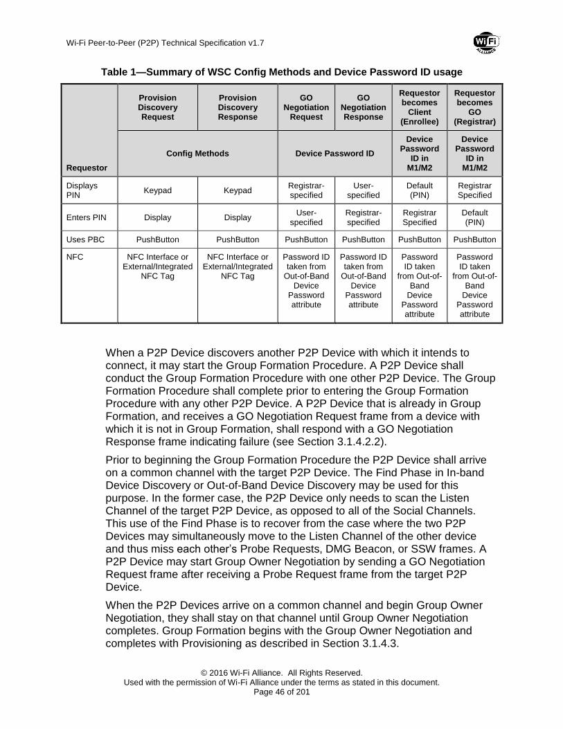
Wi-Fi Peer-to-Peer (P2P) Technical Specification v1.7
© 2016 Wi-Fi Alliance. All Rights Reserved. Used with the permission of Wi-Fi Alliance under the terms as stated in this document.
Page 46 of 201
Table 1—Summary of WSC Config Methods and Device Password ID usage
Requestor
Provision Discovery Request
Provision Discovery Response
GO Negotiation
Request
GO Negotiation Response
Requestor becomes
Client (Enrollee)
Requestor becomes
GO (Registrar)
Config Methods Device Password ID
Device Password
ID in M1/M2
Device Password
ID in M1/M2
Displays PIN
Keypad Keypad Registrar-specified
User-specified
Default (PIN)
Registrar Specified
Enters PIN Display Display User-
specified Registrar-specified
Registrar Specified
Default (PIN)
Uses PBC PushButton PushButton PushButton PushButton PushButton PushButton
NFC NFC Interface or External/Integrated
NFC Tag
NFC Interface or External/Integrated
NFC Tag
Password ID taken from
Out-of-Band Device
Password attribute
Password ID taken from
Out-of-Band Device
Password attribute
Password ID taken
from Out-of-Band
Device Password attribute
Password ID taken
from Out-of-Band
Device Password attribute
When a P2P Device discovers another P2P Device with which it intends to connect, it may start the Group Formation Procedure. A P2P Device shall conduct the Group Formation Procedure with one other P2P Device. The Group Formation Procedure shall complete prior to entering the Group Formation Procedure with any other P2P Device. A P2P Device that is already in Group Formation, and receives a GO Negotiation Request frame from a device with which it is not in Group Formation, shall respond with a GO Negotiation Response frame indicating failure (see Section 3.1.4.2.2).
Prior to beginning the Group Formation Procedure the P2P Device shall arrive on a common channel with the target P2P Device. The Find Phase in In-band Device Discovery or Out-of-Band Device Discovery may be used for this purpose. In the former case, the P2P Device only needs to scan the Listen Channel of the target P2P Device, as opposed to all of the Social Channels. This use of the Find Phase is to recover from the case where the two P2P Devices may simultaneously move to the Listen Channel of the other device and thus miss each other’s Probe Requests, DMG Beacon, or SSW frames. A P2P Device may start Group Owner Negotiation by sending a GO Negotiation Request frame after receiving a Probe Request frame from the target P2P Device.
When the P2P Devices arrive on a common channel and begin Group Owner Negotiation, they shall stay on that channel until Group Owner Negotiation completes. Group Formation begins with the Group Owner Negotiation and completes with Provisioning as described in Section 3.1.4.3.
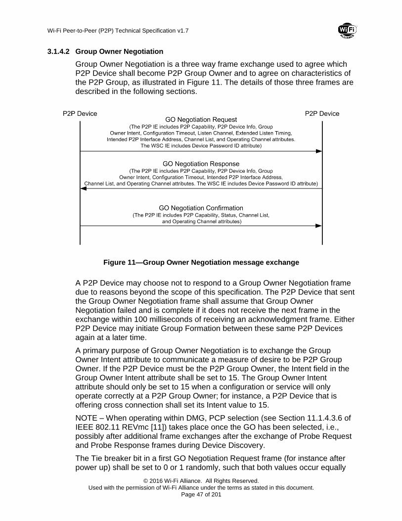
Wi-Fi Peer-to-Peer (P2P) Technical Specification v1.7
© 2016 Wi-Fi Alliance. All Rights Reserved. Used with the permission of Wi-Fi Alliance under the terms as stated in this document.
Page 47 of 201
3.1.4.2 Group Owner Negotiation
Group Owner Negotiation is a three way frame exchange used to agree which P2P Device shall become P2P Group Owner and to agree on characteristics of the P2P Group, as illustrated in Figure 11. The details of those three frames are described in the following sections.
Figure 11—Group Owner Negotiation message exchange
A P2P Device may choose not to respond to a Group Owner Negotiation frame due to reasons beyond the scope of this specification. The P2P Device that sent the Group Owner Negotiation frame shall assume that Group Owner Negotiation failed and is complete if it does not receive the next frame in the exchange within 100 milliseconds of receiving an acknowledgment frame. Either P2P Device may initiate Group Formation between these same P2P Devices again at a later time.
A primary purpose of Group Owner Negotiation is to exchange the Group Owner Intent attribute to communicate a measure of desire to be P2P Group Owner. If the P2P Device must be the P2P Group Owner, the Intent field in the Group Owner Intent attribute shall be set to 15. The Group Owner Intent attribute should only be set to 15 when a configuration or service will only operate correctly at a P2P Group Owner; for instance, a P2P Device that is offering cross connection shall set its Intent value to 15.
NOTE – When operating within DMG, PCP selection (see Section 11.1.4.3.6 of IEEE 802.11 REVmc [11]) takes place once the GO has been selected, i.e., possibly after additional frame exchanges after the exchange of Probe Request and Probe Response frames during Device Discovery.
The Tie breaker bit in a first GO Negotiation Request frame (for instance after power up) shall be set to 0 or 1 randomly, such that both values occur equally

Wi-Fi Peer-to-Peer (P2P) Technical Specification v1.7
© 2016 Wi-Fi Alliance. All Rights Reserved. Used with the permission of Wi-Fi Alliance under the terms as stated in this document.
Page 48 of 201
on average. On subsequent GO Negotiation Request frames except retransmissions, the Tie breaker bit shall be toggled. The Tie breaker bit in a GO Negotiation Response frame shall be toggled from the corresponding GO Negotiation Request frame.
If the Intent values in the GO Negotiation Request and Response frames are equal and less than 15, then the device sending the Tie breaker bit equal to 1 becomes the GO.
Group Owner determination is depicted in Figure 12.
Figure 12—Group Owner determination flowchart
3.1.4.2.1 GO Negotiation Request
A P2P Device shall initiate Group Owner Negotiation by sending the GO Negotiation Request frame. The GO Negotiation Request frame shall include a P2P IE with the P2P Capability, P2P Device Info, Channel List, Listen Channel, Operating Channel, Group Owner Intent, Configuration Timeout and Intended P2P Interface Address attributes and a WSC IE with the Device Password ID attribute.
The Group Capability Bitmap field in the P2P Capability attribute indicates the characteristics of the P2P Group to be formed if the P2P Device sending the GO Negotiation request becomes Group Owner.
The Channel List attribute shall indicate the channels that the P2P Device can support as Operating Channel of the P2P Group if it becomes P2P Group Owner. The Operating Channel attribute includes a preferred Operating Channel. See Section 3.4.2 for additional rules on channel selection.
The Configuration Timeout attribute contains the maximum time that the P2P Device needs after completion of Group Owner Negotiation to be available to

Wi-Fi Peer-to-Peer (P2P) Technical Specification v1.7
© 2016 Wi-Fi Alliance. All Rights Reserved. Used with the permission of Wi-Fi Alliance under the terms as stated in this document.
Page 49 of 201
start Provisioning. The Intended P2P Interface Address attribute contains the P2P Interface Address that the P2P Device shall use during Provisioning if Group Owner Negotiation succeeds.
The Device Password ID attribute shall indicate the source of the Provisioning information that the P2P Device shall use in the WSC procedure. If the Provisioning information is a PIN from a display of the sending device the value shall be ‘Registrar-specified’. If the Provisioning information is a PIN that was entered by a user of the sending device, the value shall be ‘User-specified’. If the sending P2P Device is using the PBC method the value shall be ‘PushButton’.
3.1.4.2.2 GO Negotiation Response
The P2P Device receiving a GO Negotiation Request frame shall examine the received information and respond with a GO Negotiation Response frame.
The P2P Device shall indicate its intent to enter Group Formation by sending a GO Negotiation Response frame that indicates a Status of Success. The GO Negotiation Response frame shall include a P2P IE with the P2P Capability, Status, P2P Device Info, Channel List, Operating Channel, Group Owner Intent, Configuration Timeout and Intended P2P Interface Address attributes and a WSC IE with the Device Password ID attribute.
A P2P Device may decline Group Owner Negotiation for any reason and shall send a GO Negotiation Response frame with the Status Code set to one of the “fail” codes in the Status attribute, as defined in Table 8.
A P2P Device that does not have the Provisioning information shall respond with a GO Negotiation Response frame that includes the Status attribute with the Status Code field set to “Fail; information is currently unavailable”. If Provisioning information becomes available as a result of user input (Pushbutton, or Keypad Config Methods) within 120 seconds, the P2P Device shall restart Group Formation by sending a GO Negotiation Request frame to the requesting P2P Device. If the user input within this time window is to explicitly reject the Group Formation request, the P2P Device shall take no further action. A requesting P2P Device can assume that there will be no attempt to restart Group Formation if it does not receive a GO Negotiation Request frame within 120 seconds of receiving the GO Negotiation Response with Status Code “Fail: information is currently unavailable”.
A P2P Device that is already in Group Formation that receives a GO Negotiation Request frame from a P2P Device with which it is not in Group Formation, shall respond with a GO Negotiation Response frame that includes the Status attribute with the Status Code field set to “Fail; unable to accommodate request”.
If a P2P Device that must be P2P Group Owner (i.e. that P2P Device would indicate an Intent value of 15) receives GO Negotiation Request frame that also contains an Intent value of 15, the P2P Device shall respond with a GO

Wi-Fi Peer-to-Peer (P2P) Technical Specification v1.7
© 2016 Wi-Fi Alliance. All Rights Reserved. Used with the permission of Wi-Fi Alliance under the terms as stated in this document.
Page 50 of 201
Response frame containing a Status attribute with the Status Code field set to “Fail: both P2P Devices indicated an Intent of 15 in Group Owner Negotiation”.
Group Formation ends on transmission or reception of a GO Negotiation Response frame with the Status Code set to a value other than Success. A P2P Device may either subsequently enter, or continue Group Formation with other P2P Devices. Either P2P Device may initiate Group Formation between these same P2P Devices again at a later time.
Two P2P Devices that have discovered each other may send a GO Negotiation Request frame to the other. In this case only the P2P Device with the highest P2P Device Address shall send a GO Negotiation Response frame. If both P2P Devices have indicated an Intent value of 15, the P2P Device with the highest P2P Device Address shall send the GO Negotiation Response frame indicating failure as above.
If the Status is Success the Group Owner Intent attribute included in the GO Negotiation Response frame shall indicate its Intent value to be a Group Owner. The interpretation of P2P IE fields in the GO Negotiation Response frame depends on whether the P2P Device will become P2P Group Owner on successful completion of Group Formation.
A P2P Device that will become the P2P Group Owner constructs the GO Negotiation Response frame corresponding to the following rules. The Channel List attribute shall indicate the channels that the P2P Device may use as Operating Channel of the P2P Group. The channels indicated in the Channel List shall only include channels from the Channel List attribute in the GO Negotiation Request frame. The Operating Channel attribute shall indicate the intended Operating Channel of the P2P Group. The channel indicated in the Operating Channel attribute shall be one of the channels in the Channel List attribute in the GO Negotiation Response frame. The P2P Group ID attribute shall contain the intended SSID of the P2P Group. The Group Capability Bitmap field in the P2P Capability attribute shall indicate the characteristics of the P2P Group to be formed. The Persistent P2P Group, Intra-BSS Distribution, Cross Connection and Persistent Reconnect bits in the Group Capability Bitmap field in the P2P Capability attribute in Beacon and Probe Response frames transmitted by the P2P Group Owner of the P2P Group formed, shall be the same as within the Group Capability Bitmap field in the P2P Capability attribute in the GO Negotiation Response frame.
A P2P Device that will become a P2P Client constructs the GO Negotiation Response frame corresponding to the following rules. The Channel List attribute shall indicate the channels that the P2P Device can support as Operating Channel of the P2P Group. The channels indicated in the Channel List may be determined independently from the channels in the Channel List attribute in the GO Negotiation Request frame. The Operating Channel attribute may indicate a preferred Operating Channel of the P2P Group, or may be omitted. Any channel indicated in the Operating Channel attribute shall be one of the channels in the Channel List attribute in the GO Negotiation Response frame. All bits in the
Wi-Fi Peer-to-Peer (P2P) Technical Specification v1.7
© 2016 Wi-Fi Alliance. All Rights Reserved. Used with the permission of Wi-Fi Alliance under the terms as stated in this document.
Page 51 of 201
Group Capability Bitmap field of the P2P Capability attribute shall be reserved. A P2P Device may decline Group Owner Negotiation if the characteristics of the P2P Group indicated in the Group Capability Bitmap field of the P2P Capability attribute in the GO Negotiation Request frame are not acceptable e.g. this will be a Persistent P2P Group and it cannot support a Persistent P2P Group, as defined in 3.2.5. In this case, the P2P Device shall send a GO Negotiation Response frame with the Status Code set to “Fail; incompatible parameters”.
The Configuration Timeout attribute contains the maximum time that the P2P Device needs after completion of Group Owner Negotiation to be available to start Provisioning. The Intended P2P Interface Address attribute contains the P2P Interface Address that the P2P Device shall use during Provisioning if Group Owner Negotiation succeeds.
The Device Password ID attribute included in the WSC IE shall indicate the source of the Provisioning information that the P2P Device shall use. If the Provisioning information is a PIN from a display of the sending device the value shall be ‘Registrar-specified’. If the Provisioning information is a PIN that was entered by a user of the sending device the value shall be ‘User-specified’. If the sending P2P Device is using the PBC method the value shall be ‘PushButton’.
A P2P Device may decline Group Owner Negotiation if the Device Password ID in the GO Negotiation Request is incompatible with the information it shall use to execute Provisioning. In this case, the P2P Device shall send a GO Negotiation Response frame with the Status Code set to “Fail; incompatible provisioning method”.
3.1.4.2.3 GO Negotiation Confirmation
Upon receipt of the GO Negotiation Response frame with a Status Code indicating Success, the P2P Device shall examine the received information, and respond with a GO Negotiation Confirmation frame. The Status attribute included in the GO Negotiation Confirmation frame shall indicate whether the GO Negotiation succeeds or fails. It may fail for any reason; typical reasons may be lack of commonly available channel, incompatible parameters related to settings in the Group Capability Bitmap field of the P2P Capability attribute, etc.
If the Status is Success the interpretation of fields in the GO Negotiation Confirmation frame depends on whether the P2P Device that sent the frame will become P2P Group Owner on successful completion of Group Formation.
A P2P Device that will become the P2P Group Owner constructs the GO Negotiation Confirmation frame corresponding to the following rules. The Channel List attribute shall indicate the channels that the P2P Device may use as Operating Channel of the P2P Group. The channels indicated in the Channel List shall only include channels from the Channel List attribute in the GO Negotiation Response frame. The Operating Channel attribute shall indicate the intended Operating Channel of the P2P Group. The channel indicated in the Operating Channel attribute shall be one of the channels in the Channel List

Wi-Fi Peer-to-Peer (P2P) Technical Specification v1.7
© 2016 Wi-Fi Alliance. All Rights Reserved. Used with the permission of Wi-Fi Alliance under the terms as stated in this document.
Page 52 of 201
attribute in the GO Negotiation Confirmation frame. The P2P Group ID attribute shall contain the intended SSID of the P2P Group. The Group Capability Bitmap field in the P2P Capability attribute shall be the same as in the GO Negotiation Request frame. The Persistent P2P Group, Intra-BSS Distribution, Cross Connection and Persistent Reconnect bits in the Group Capability Bitmap field in the P2P Capability attribute in the beacon of the group formed shall be the same as within the Group Capability Bitmap field in the P2P Capability attribute in the GO Negotiation Confirmation frame.
A P2P Device that will become a P2P Client constructs the GO Negotiation Confirmation frame corresponding to the following rules. The Channel List attribute shall indicate the channels that the P2P Device can support as Operating Channel of the P2P Group. The channels indicated in the Channel List shall only include channels from the Channel List attribute in the GO Negotiation Response frame and shall include the channel indicated in the Operating Channel attribute in the GO Negotiation Response frame. The Operating Channel attribute in the GO Negotiation Confirmation frame shall be the Operating Channel attribute from the GO Negotiation Response frame. All bits in the Group Capability Bitmap field of the P2P Capability attribute shall be reserved. A P2P Device may decline Group Owner Negotiation if the characteristics of the P2P Group indicated in the Group Capability Bitmap field of the P2P Capability attribute in the GO Negotiation Response frame are not acceptable e.g. this will be a Persistent P2P Group and it cannot support a Persistent P2P Group, as defined in 3.2.5. In this case, the P2P Device shall send a GO Negotiation Confirmation frame with the Status Code set to “Fail; incompatible parameters”.
A P2P Device may decline Group Owner Negotiation if the Device Password ID in the GO Negotiation Response is incompatible with the Provisioning information it shall use to execute Provisioning. In this case, the P2P Device shall send a GO Negotiation Confirmation frame with the Status Code set to “Fail; incompatible provisioning method”.
3.1.4.3 Provisioning
To allow for P2P Device configuration, P2P Devices may delay starting the Provisioning phase until the expiration of the maximum of the P2P Group Owners GO Configuration Time and the P2P Clients Client Configuration Time from the respective Configuration Timeout attributes exchanged during Group Owner Negotiation.
The P2P Device selected as P2P Group Owner during Group Owner Negotiation shall start a P2P Group session as described in Section 3.2.2 using the Credentials it intends to use for that group. The P2P Group Owner shall use the Operating Channel indicated during Group Owner Negotiation, if available. The P2P Client shall connect to the P2P Group Owner to obtain Credentials. If the Operating Channel is not available the P2P Group Owner shall use another channel from the Channel List attribute sent in the GO Negotiation Confirmation frame. The P2P Client may have to scan to find the P2P Group Owner if the
Wi-Fi Peer-to-Peer (P2P) Technical Specification v1.7
© 2016 Wi-Fi Alliance. All Rights Reserved. Used with the permission of Wi-Fi Alliance under the terms as stated in this document.
Page 53 of 201
intended Operating Channel is not available. The Group Formation bit in the P2P Group Capability Bitmap of the P2P Capability attribute shall be set to 1 until Provisioning succeeds.
Provisioning shall be executed as described in Wi-Fi Simple Configuration [2] with the following modifications:
The P2P Group Owner shall serve the role as the AP with Internal Registrar for operation outside DMG and shall serve the role as the PCP with Internal Registrar for operation within DMG. It shall only allow association by the P2P Device that it is currently in Group Formation with. Since the user has entered the WSC PIN or triggered the WSC PushButton functionality on both devices, the Registrar shall send M2 in response to M1 and shall not send M2D.
The P2P Client shall serve the role as the STA Enrollee. It shall associate to the P2P Device that it is currently in Group Formation with.
P2P Devices that have either a keypad or display shall support WSC PIN and PBC. P2P Devices that have neither keypad nor display shall support WSC PBC. P2P Devices shall not use WSC Label Configuration Method with other P2P Devices.
If Provisioning fails then Group Formation ends and the P2P Group Owner shall end the P2P Group session as described in Section 3.2.9. If Provisioning fails the P2P Device may retry Group Formation or return to Device Discovery.
On successful completion of Provisioning the P2P Group Owner shall set the Group Formation bit in the P2P Group Capability Bitmap of the P2P Capability attribute to 0. At this point the P2P Client may join the P2P Group using the Credentials supplied during Provisioning.
3.1.4.4 Group Formation using Out-of-Band Device Discovery
When a P2P Device discovers another P2P Device with which it intends to connect using an optional Out-of-Band Device Discovery, it may start the Group Formation Procedure. A P2P Device shall conduct the Group Formation Procedure with one other P2P Device over the common channel specified in the Group Owner Negotiation channel attribute as shown in Figure 13.

Wi-Fi Peer-to-Peer (P2P) Technical Specification v1.7
© 2016 Wi-Fi Alliance. All Rights Reserved. Used with the permission of Wi-Fi Alliance under the terms as stated in this document.
Page 54 of 201
Figure 13—Example of Group Formation using NFC Out-of-Band Device Discovery
3.1.5 P2P Invitation procedure
The P2P Invitation Procedure is an optional procedure used for the following:
3. A P2P Group Owner inviting a P2P Device to become a P2P Client in its P2P Group.
4. A P2P Client inviting another P2P Device to join the P2P Group of which the P2P Client is a member because it wishes to use some service of the P2P Device.
5. Requesting to invoke a Persistent P2P Group for which both P2P Devices have previously been provisioned and one of the Devices is P2P Group Owner for the Persistent P2P Group.
A P2P Device that is invited to join an operational P2P Group through successful completion of the P2P Invitation Procedure, i.e. (1) or (2) above, may:

Wi-Fi Peer-to-Peer (P2P) Technical Specification v1.7
© 2016 Wi-Fi Alliance. All Rights Reserved. Used with the permission of Wi-Fi Alliance under the terms as stated in this document.
Page 55 of 201
Use Wi-Fi Simple Configuration [2] to obtain Credentials. Provision Discovery and Wi-Fi Simple Configuration will take place on the Operating Channel of the P2P Group Owner.
If the P2P Device is provisioned, connect to the P2P Group as described in Section 3.2.3.
3.1.5.1 P2P Invitation Request
A P2P Invitation Request frame may be transmitted by:
A P2P Device that is a member of a P2P Group (i.e. P2P Group Owner or P2P Client) to another P2P Device that supports P2P Invitation Procedure signaling and is currently not a member of the P2P Group to invite that P2P Device to join the P2P Group. When used for this purpose, the Invitation Type in the Invitation Flags attribute included in the P2P Invitation Request frame shall be set to 0.
A P2P Device that is a member of a Persistent P2P Group to another member of that P2P Group and one of the Devices is the P2P Group Owner, to request that the P2P Group be invoked. When used for this purpose, the Invitation Type in the Invitation Flags attribute included in the P2P Invitation Request frame shall be set to 1.
The contents of the P2P Invitation Request frame depend on the role of the sending device in the P2P Group (in the case of requesting to invoke a Persistent P2P Group, the role of the device in that Persistent P2P Group).
A P2P Invitation Request frame transmitted by a P2P Group Owner shall include the P2P Group ID, P2P Group BSSID, Channel List, Operating Channel, and Configuration Timeout attributes in the P2P IE. The Channel List attribute shall indicate the channels that the P2P Device can support as Operating Channel of the P2P Group. The Operating Channel and Configuration Timeout attributes shall be set as follows:
If the P2P Invitation Request frame is transmitted by a P2P Group Owner inviting a P2P Device to become a P2P Client in its P2P Group, the Operating Channel attribute indicates the Operating Channel of the P2P Group. The GO Configuration Timeout field in the Configuration Timeout attribute shall be set to 0.
If the P2P Invitation Request frame is transmitted by a P2P Device requesting to invoke a Persistent P2P Group of which it is P2P Group Owner, the Operating Channel attribute indicates the intended Operating Channel of the P2P Group. The Configuration Timeout attribute shall indicate the configuration time required for the P2P Group Owner to start the P2P Group session after a P2P Invitation Response that indicates success.
If a P2P Group Owner is transmitting the Invitation Request frame after NFC Static Handover, and intends to use the Device Password read from the NFC Tag in the subsequent WSC exchange, then it also shall include a WSC IE in its
Wi-Fi Peer-to-Peer (P2P) Technical Specification v1.7
© 2016 Wi-Fi Alliance. All Rights Reserved. Used with the permission of Wi-Fi Alliance under the terms as stated in this document.
Page 56 of 201
P2P Invitation Request and places the Device Password ID read from the NFC Tag in a Device Password ID attribute within the WSC IE.
A P2P Invitation Request frame transmitted by a P2P Client shall include the P2P Group ID, Channel List and Configuration Timeout attributes. The Channel List attribute shall indicate the channels that the inviting P2P Device can support as Operating Channel of the P2P Group. An Operating Channel attribute may also be included: rules for inclusion of the Operating Channel attribute and setting of the Configuration Timeout attribute are as follows:
If the P2P Invitation Request frame is transmitted by a P2P Client inviting a P2P Device to join the P2P Group of which it is a member, P2P Group BSSID and Operating Channel attributes shall also be present, indicating the BSSID and Operating Channel of the P2P Group, respectively. The Client Configuration Timeout field in the Configuration Timeout attribute shall be set to 0.
If the P2P Invitation Request frame is transmitted by a P2P Device requesting to invoke a Persistent P2P Group in which it is a P2P Client, an Operating Channel attribute may be present to indicate a preferred Operating Channel. The Configuration Timeout attribute shall indicate the configuration time required to the point that the P2P Client is ready to join the P2P Group after a P2P Invitation Response that indicates success. The P2P Device that sent the P2P Invitation Request frame shall assume that process failed if it does not receive a P2P Invitation Response frame within 100 milliseconds of issuing the P2P Invitation Request frame.
3.1.5.2 P2P Invitation Response
A P2P Device that receives a P2P Invitation Request frame and supports the P2P Invitation Procedure signaling shall return a P2P Invitation Response frame. If the P2P Device accepts the invitation it shall set the Status attribute in the response to success. If the P2P Device does not accept the invitation it shall set the Status attribute to the appropriate failure code. The decision to accept or deny the P2P Invitation Request frame is left to P2P Device’s implementation policy.
A P2P Invitation Response frame (with the Status attribute set to Success) transmitted by the P2P Group Owner of a Persistent P2P Group in response to a request to invoke that P2P Group, shall include the P2P Group BSSID, Channel List, Operating Channel and Configuration Timeout attributes to indicate the Group BSSID, potential Operating Channels, intended Operating Channel and any GO Configuration Time. The channels in the Channel List shall only include channels from the Channel List attribute in the P2P Invitation Request frame. The channel indicated in the Operating Channel attribute shall be one of the channels in the Channel List attribute. In the case where there are no channels commonly supported by the P2P Devices the P2P Invitation Response frame shall include a Status attribute with the Status Code field set to “Fail; no common channels”.

Wi-Fi Peer-to-Peer (P2P) Technical Specification v1.7
© 2016 Wi-Fi Alliance. All Rights Reserved. Used with the permission of Wi-Fi Alliance under the terms as stated in this document.
Page 57 of 201
A P2P Invitation Response frame (with the Status attribute set to Success) transmitted by an invited P2P Client or the P2P Device that is a P2P Client in a Persistent P2P Group, shall include the Channel List and Configuration Timeout attributes. The Channel List indicates the Operating Channels the P2P Client can support. The channels in the Channel List shall only include channels from the Channel List attribute in the P2P Invitation Request frame. The Configuration Timeout attribute shall indicate the configuration time required to the point that the P2P Client is ready to join the P2P Group after a P2P Invitation Response that indicates success. In the case where there are no channels commonly supported by the P2P Devices, or the current operating channel is not supported by the responding P2P Client, the P2P Invitation Response frame shall include a Status attribute with the Status Code field set to “Fail; no common channels”.
The invited P2P Device may also pass the invitation request to a higher layer. In this case it shall respond with a P2P Invitation Response frame with a Status attribute with the Status Code field set to “Fail: information is currently unavailable”. The invited P2P Device shall not wait for any action from a higher layer to send the P2P Invitation Response frame. The P2P attributes returned in the P2P Invitation Response frame shall be as previously described for ‘Success’, with the exception that inclusion of the Operating Channel attribute is optional when the P2P Invitation Response frame is sent by the P2P Group Owner of a Persistent P2P Group in response to a request to invoke that P2P Group. The Configuration Timeout attribute returned in the P2P Invitation Response frame shall be ignored by the inviting P2P Device.
A P2P Device that receives an Invitation Request frame with an Invitation Type in the Invitation Flags attribute set to 1, indicating a request to re-invoke a Persistent Group, and an unknown P2P Group ID, shall respond with an Invitation Response frame with a Status attribute with the Status Code field set to “Fail: unknown P2P Group”.
A P2P Client that has an NFC Tag, supports NFC Static Handover and which receives an Invitation Request from a P2P Group Owner that contains a WSC IE with a Device Password ID attribute, shall compare the Device Password ID from the WSC IE with the Device Password ID from its NFC Tag. If the Device Password IDs match, then the P2P Client may proceed to join the P2P Group and use the Device Password ID and Device Password from its Tag in the subsequent WSC exchange.
3.1.5.3 Use of the Invitation Procedure to invoke a Persistent P2P Group.
A P2P Group Owner may invoke a Persistent P2P Group at any time by starting a P2P Group session as described in Section 3.2.2. Optionally, it may choose to only start the P2P Group session after a successful P2P Invitation Request and Response frames exchange with a member of that P2P Group. In such a case, the P2P Group can only be invoked by P2P Devices that support the P2P Invitation Procedure signaling. Thus all P2P Devices that are capable of

Wi-Fi Peer-to-Peer (P2P) Technical Specification v1.7
© 2016 Wi-Fi Alliance. All Rights Reserved. Used with the permission of Wi-Fi Alliance under the terms as stated in this document.
Page 58 of 201
supporting Persistent P2P Groups shall support the P2P Invitation Procedure signaling.
A P2P Client that desires to invoke a Persistent P2P Group shall first discover the P2P Device that is the P2P Group Owner for this Persistent P2P Group and then successfully complete a P2P Invitation exchange with that device. The Invitation Type in the Invitation Flags attribute included in the Invitation Request frame in this exchange shall be set to 1.
A P2P Device that receives an Invitation Request frame to re-invoke a Persistent Group shall ignore the Config Methods field in the P2P Device Info attribute.
A P2P Device that receives an Invitation Request frame to re-invoke a Persistent Group and responds with a P2P Invitation Response frame with a Status attribute with the Status Code field set to “Fail: information is currently unavailable” shall behave as follows:
If a response is received from higher layers within 120 seconds (e.g. as a result of user input) authorizing the request, the invited P2P Device shall restart the Invitation procedure by sending an Invitation Request frame to the requesting P2P Device.
If the higher-layer response within this time window is to explicitly reject the Group Formation request, the invited P2P Device shall take no further action.
The requesting P2P Device can assume that there will be no attempt to restart the Invitation Procedure if it does not receive an Invitation Request frame within 120 seconds of receiving the Invitation Response with Status Code “Fail: information is currently unavailable”.
To allow for P2P Device configuration, P2P Devices that are reinvoking a P2P Group may delay starting the P2P Group session until the expiration of the maximum of the P2P Group Owners GO Configuration Time and the P2P Clients Client Configuration Time from the respective Configuration Timeout attributes exchanged during P2P Invitation.
If the P2P Client does not detect the presence of the P2P Group Owner on the intended Operating Channel it shall scan the channels in the Channel List in the P2P Invitation Response frame. The P2P Group Owner may be operating on a different channel, for example if the intended Operating Channel is not available when the P2P Group is invoked.
3.2 P2P Group operation
P2P Group operation outside DMG closely resembles infrastructure BSS operation as defined in IEEE 802.11-2012 [1] with the P2P Group Owner assuming the role of the AP and the P2P Client assuming the role of the STA. The similarities and differences between infrastructure BSS and P2P Group operation outside DMG are described in this section.
Wi-Fi Peer-to-Peer (P2P) Technical Specification v1.7
© 2016 Wi-Fi Alliance. All Rights Reserved. Used with the permission of Wi-Fi Alliance under the terms as stated in this document.
Page 59 of 201
P2P Group operation within DMG follows PBSS operation as defined in IEEE 802.11-REVmc [11] with the P2P Group Owner operating as the PCP and the P2P Client operating as a non-PCP/non-AP STA. Additional mechanisms applicable to P2P Group operation within DMG are described in this section.
3.2.1 P2P Group ID
The P2P Group Owner shall assign a globally unique P2P Group ID for each P2P Group when the P2P Group is formed and this shall remain the same for the lifetime of that P2P Group. The format of the P2P Group ID attribute is defined in Section 4.1.17.
The P2P Group ID contains the globally unique P2P Device Address of the P2P Group Owner which assures that different P2P Devices create P2P Groups differentiated from each other. A P2P Group Owner shall determine the Credentials that are required to join a P2P Group. The Credentials shall be fresh for each P2P Group formed. The Credentials for a P2P Group issued to a P2P Device shall:
Use WPA2-Personal as Authentication Type.
Use AES as Encryption Type.
Use a Network Key Type of 64 Hex characters.
Use a different SSID for each group to assure that all P2P Groups are unique.
A P2P Group Owner shall maintain a WPA2-Personal pass-phrase for delivery to Legacy Clients or to allow a network to be established without WSC. This may be delivered using WSC, or in the case of a Legacy Client that does not support WSC, by means outside the scope of this specification. The PSK is derived from the pass-phrase and SSID. The WPA2-Personal pass-phrase shall contain at least eight ASCII characters randomly selected with a uniform distribution from the following character set: upper case letters, lower case letters and numbers.
Each SSID shall begin with the ASCII characters “DIRECT-“. This SSID requirement may enable users of Legacy Clients to differentiate between a P2P Group and an infrastructure network. Following “DIRECT-“ the SSID shall contain two ASCII characters “xy”, randomly selected with a uniform distribution from the following character set: upper case letters, lower case letters and numbers. This SSID requirement makes the probability low that a Legacy Client encounters two P2P Groups with the same SSID and mistakenly attempt to roam between them. Any byte values allowed for an SSID according to IEEE802.11-2012 [1] may be included after the string “DIRECT-xy” (including none).
3.2.2 Starting and maintaining a P2P Group session
The P2P Group Owner may be determined through the Group Formation Procedure described in Section 3.1.4. The P2P Group Owner may be set by

Wi-Fi Peer-to-Peer (P2P) Technical Specification v1.7
© 2016 Wi-Fi Alliance. All Rights Reserved. Used with the permission of Wi-Fi Alliance under the terms as stated in this document.
Page 60 of 201
configuration, for example when connecting to a Legacy Client or when cross connection is provided etc. The P2P Group Owner shall assign a P2P Interface Address that it shall use as its MAC address and BSSID for the duration of the P2P Group session. The P2P Group Owner shall select an Operating Channel, following any procedures required for operation in a certain frequency band in a particular regulatory domain. On that Operating Channel, the P2P Group Owner shall transmit probe responses in response to probe requests, and shall transmit beacons advertising the TSF (for timing synchronization), required operational parameters, supported capabilities, membership, and services available within the P2P Group.
A P2P Group Owner shall respond to Probe Request frames following the rules in IEEE 802.11-2012 [1] for operation outside DMG and the rules in IEEE 802.11-REVmc [11] for operation within DMG, with the following modifications:
The P2P Wildcard SSID shall be treated the same as the Wildcard SSID for the purposes of deciding to transmit a response (i.e. in IEEE 802.11-2012 [1], Clause Section 11.1.3.2.1, change “The SSID in the probe request is the wildcard SSID or the specific SSID of the STA” to “The SSID in the probe request is the wildcard SSID, the P2P wildcard SSID, or the specific SSID of the STA,”)
When a P2P Group Owner responds to a Probe Request frame containing the P2P IE it shall include the P2P Group Info attribute in the P2P IE in the Probe Response frame. The P2P IE shall include the P2P Group Info attribute unless there are zero connected P2P Clients. A P2P Group Owner shall not include a P2P IE in the Probe Response frame if the received Probe Request frame does not contain a P2P IE.
If one or more Requested Device Type attributes are present in the Probe Request frame, a P2P Group Owner shall only respond with a Probe Response frame if it has one or more Primary or Secondary Device Type values identical to any of the Requested Device Type values, or if it has a connected P2P Client with one or more Primary or Secondary Device Type values identical to any of the Requested Device Type values. The P2P Group Owner may filter the P2P Group Information returned in the Probe Response frame to include only devices with matching Primary or Secondary Device Type values.
If a Device ID attribute is present in the P2P IE in a Probe Request frame, a P2P Group Owner shall only respond with a Probe Response frame if its Device Address, or the Device Address of a connected P2P Client matches that in the Device Address field in the Device ID attribute.
In all Probe Responses that it sends, a P2P Group Owner shall set the SSID to the SSID of the group, and shall set the SA and BSSID to its P2P Interface Address.
For operation outside DMG, a P2P Group Owner shall set the ESS subfield to 1 and the IBSS subfield to 0 in the Capability Information field of Beacon and Probe Response frames that it sends. For operation within DMG, a P2P Group

Wi-Fi Peer-to-Peer (P2P) Technical Specification v1.7
© 2016 Wi-Fi Alliance. All Rights Reserved. Used with the permission of Wi-Fi Alliance under the terms as stated in this document.
Page 61 of 201
Owner shall set the BSS Type field to 2 (PBSS) in DMG Beacon, Probe Response and (Re)Association Response frames that it sends.
A P2P Device shall indicate that it is a P2P Group Owner by setting the Group Owner field of the P2P Capability attribute to 1 in transmitted Beacon, Announce, and Probe Response frames. A P2P Device operating within DMG that includes the P2P element in DMG Beacon frames shall indicate that it is a P2P Group Owner by setting the Group Owner field of the P2P Capability attribute to 1. The P2P Group Limit field in the P2P Capability attribute shall be set to 0 to indicate that additional P2P connections are supported in this P2P Group, and set to 1 if no further P2P connections are supported. A P2P Group Owner shall be able to support a minimum of one Client.
A P2P Device shall include the WSC IE in all transmitted Beacon, Announce, Probe Request and Response frames. A P2P Device operating within DMG may include the WSC IE in transmitted DMG Beacon frames (see Section 4.3.1). Both the Device Name and Primary Device Type are required attributes in the WSC IE. The Secondary Device Type List is an optional attribute in the WSC IE. The inclusion of the WSC IE in the Probe Response frame sent by a P2P Device allows it to advertise human-readable device-specific information. It should be noted that this information is openly advertised.
A Client acquires the Group Credentials through static configuration or through Wi-Fi Simple Configuration [2]. When using Wi-Fi Simple Configuration [2], the P2P Group Owner shall serve as the WSC Registrar and the Client shall serve as the WSC Enrollee.
A P2P Group Owner shall conform to the relevant sections of IEEE 802.11-2012 [1] when operating at 5GHz. A P2P Group Owner that desires to change the Operating Channel during a P2P Group session shall use the Extended Channel Switch Announcement as defined in IEEE 802.11-2012 [1] to inform P2P Clients. Alternatively, the P2P Group Owner may perform the Fast Session Transfer (FST) protocol defined in Section 11.33.2 of IEEE 802.11-REVmc [11] with one or more P2P Clients to change the Operating Channel or to move the operation of select streams belonging to a P2P Client to a new band/channel. If the Operating Channel is changed as a result of using the FST protocol, then any P2P Client that does not switch to the new Operating Channel shall be disconnected (see Section 3.2.6.2).
3.2.3 Connecting to a P2P Group
A P2P Device discovers a P2P Group or another P2P Device using the Device Discovery procedure described in 3.1.2.
Prior to connecting to the P2P Group the P2P Device shall assign a P2P Interface Address that it shall use as the MAC address of the P2P Client for the duration of the P2P Group session. When a P2P Device joins an existing P2P Group that it has not stored a credential for, it shall send a Provision Discovery Request frame with a single method set in the Config Methods attribute to

Wi-Fi Peer-to-Peer (P2P) Technical Specification v1.7
© 2016 Wi-Fi Alliance. All Rights Reserved. Used with the permission of Wi-Fi Alliance under the terms as stated in this document.
Page 62 of 201
indicate the desire to enroll in the network, except when NFC Negotiated or Static Handover is in use.
The Provision Discovery Request frame shall be sent to the P2P Device Address of the P2P Group Owner and on the operating channel of the P2P Group. The P2P Group Owner may use this frame as a trigger that a device wants to enroll (maybe an indication can be shown to the user). A P2P Group Owner shall respond to a received Provision Discovery Request frame with a Provision Discovery Response frame. The Config Methods attribute in the Provision Discovery Response frame may have the same method set as in the received Provision Discovery Request frame to indicate success or shall be null to indicate failure. The P2P Client that sent the Provision Discovery Request frame shall assume that process failed if it does not receive a Provision Discovery Response frame within 100 milliseconds of issuing the Provision Discovery Request frame. A P2P Client may proceed regardless of the status of the Provision Discovery Response status.
The P2P Client acquires the Group Credentials through static configuration or through Wi-Fi Simple Configuration [2]. When using Wi-Fi Simple Configuration [2], the P2P Group Owner shall serve as the WSC Registrar and the P2P Client shall serve as the WSC Enrollee. In order to connect to a P2P Group, the P2P Client operating outside DMG, using the Credentials, shall engage in the authentication procedure in Section 10.3.4.2 of IEEE 802.11-2012 [1] and the association procedure in Section 10.3.5.2 of IEEE 802.11-2012 [1] with the P2P Group Owner. In order to connect to a P2P Group, the P2P Client operating within DMG, using the Credentials, shall engage in the association procedure in Section 11.3.5.2 of IEEE 802.11-REVmc [11] with the P2P Group Owner.
A P2P Client shall not attempt to connect to a P2P Group that has the Group Formation bit in the P2P Group Capability Bitmap of the P2P Capability attribute set to 1 unless it is in Group Formation with that P2P Device, as described in 3.1.4.
When a P2P Client associates with a P2P Group Owner, it provides its Device Name, Primary Device Type, and optionally Secondary Device Type List information to the P2P Group Owner by including the P2P Device Info attribute (see Section 4.1.15) and the P2P Capability attribute (see Section 4.1.4) in the P2P IE in the Association Request frame. This information shall be used by the P2P Group Owner for Group Information Advertisement.
When using PIN based WSC, the selected PIN (from the display of either the P2P Client or P2P Group Owner) is indicated using Device Password ID attribute in the WSC M1/M2 messages as shown in Table 1 (when connecting to a P2P Group, the requestor always becomes P2P Client).
3.2.4 P2P Group Owner services for P2P Client discovery
Group Information Advertisement provides a mechanism to discover a P2P Device that is a P2P Client in an existing P2P Group. A P2P Group Owner shall advertise the device information of the P2P Clients currently connected to the

Wi-Fi Peer-to-Peer (P2P) Technical Specification v1.7
© 2016 Wi-Fi Alliance. All Rights Reserved. Used with the permission of Wi-Fi Alliance under the terms as stated in this document.
Page 63 of 201
P2P Group by including the P2P Group Info attribute in Probe Response frames according to the rules above. The P2P Group Owner shall include a P2P Client Info Descriptor in the P2P Group Info attribute for each P2P Client that is connected to the P2P Group. Once the P2P Group Owner determines that a P2P Client has left the P2P Group, the P2P Client Info Descriptor for that Client shall be removed from the P2P Group Info attribute. The P2P Group Owner shall not include a P2P Group Info attribute if it has zero connected P2P Clients.
For operation within DMG, a P2P Device may transmit an Information Request frame to the P2P Group Owner to discover other P2P Clients that are a member of the P2P Group as specified in Section 11.30.1 of IEEE 802.11-REVmc [11]. The P2P Group Owner shall transmit an unsolicited Information Response frame following the association or security association of a P2P Device with the P2P Group as described in Section 11.3.7 of IEEE 802.11 REVmc [11].
A searching P2P Device may send a Device Discoverability Request frame to a P2P Group Owner to request a P2P Client that supports P2P Client Discoverability to become available for exchange of discovery information, or initiation of Group Formation. On reception of a Device Discoverability Request frame with a P2P Device ID attribute that contains the P2P Device Address of a P2P Client in the P2P Group, a P2P Group Owner shall send a GO Discoverability Request frame to the P2P Client. Delivery of the GO Discoverability Request frame may be delayed due to the P2P Client using Power save mechanisms. A P2P Client should stay constantly available for at least a 100 TU after receiving a GO Discoverability Request frame or until communication with the searching P2P Device completes. On successful delivery of the GO Discoverability Request frame the P2P Group Owner shall send the searching P2P Device a Device Discoverability Response frame indicating success in the status code. If the P2P Group Owner cannot deliver a GO Discoverability Request frame to the target P2P Device it shall send the searching P2P Device a Device Discoverability Response frame with the Status attribute indicating fail in the Status Code, as defined in Table 8.
A P2P Client that connects to a P2P Group Owner indicates support for P2P Client Discovery using the P2P Client Discovery bit in the P2P Capability attribute in the Association Request frame. If the P2P Client supports P2P Client Discovery, the P2P Client shall set the P2P Client Discovery bit to 1, otherwise it shall be set to 0. The P2P Client may indicate changed support for P2P Client Discovery in a subsequent (Re)association Request frame.
A searching P2P Device can determine that a P2P Client does not support P2P Client Discovery since the P2P Group Owner includes the P2P Capability attribute of each P2P Client within the P2P Group Info attribute. Alternatively, when operating within DMG, a searching P2P Device may also make this determination upon reception of an Information Response frame that contains the P2P Capability attribute. The following rules apply where a P2P Client has indicated it does not support P2P Client Discovery:

Wi-Fi Peer-to-Peer (P2P) Technical Specification v1.7
© 2016 Wi-Fi Alliance. All Rights Reserved. Used with the permission of Wi-Fi Alliance under the terms as stated in this document.
Page 64 of 201
A searching P2P Device shall not send a Device Discoverability Request frame to a P2P Group Owner containing the P2P Device ID of that P2P Client
A searching P2P Device shall not send any frame to the P2P Device that is that P2P Client
The P2P Group Owner shall not send a GO Discoverability Request frame to that P2P Client
A P2P Device that is a P2P Client within a P2P Group should support P2P Client Discoverability unless device or application restrictions prevent it from doing so. A P2P Device that has ended a session as P2P Group Owner of a Persistent P2P Group that has the Persistent Reconnect bit in the P2P Capability attribute set to 1 shall support P2P Client Discovery when it is a P2P Client in a P2P Group. Such a P2P Device should also select appropriate power save timing to minimize the delay in delivery of a GO Discoverability Request frame, e.g. by being available at each TBTT.
A P2P Group Owner that has one or more connected P2P Clients that have indicated support for P2P Client Discovery should take this into account in setting its own discoverability according to the recommendations in Section 3.3.2.
3.2.5 Persistent Group operation
A P2P Device that successfully obtains Credentials for a Persistent P2P Group shall store the P2P Group ID and Credentials for that P2P Group. This enables the P2P Device that is P2P Group Owner to recreate the P2P Group for additional sessions after initial formation. P2P Clients can also request that the P2P Group be restarted and use the stored Credentials to join. The P2P Group Owner of the Persistent P2P Group may also store a list of P2P Device Addresses of P2P Clients that have joined the Persistent P2P Group.
The P2P Group ID and Credentials for a Persistent P2P Group do not change for each session of that P2P Group, however, the P2P Interface Address (and therefore BSSID) and operating channel of the P2P Group may not be the same for each session. The P2P Interface Address used by P2P Clients within a Persistent P2P Group may also change for each session. The Persistent P2P Group bit in the Group Capability Bitmap field in the P2P Capability attribute shall be set in the Beacon, DMG Beacon (if the P2P IE is present in the frame), Announce, and Probe Response frames transmitted by the P2P Group Owner. The Persistent P2P Group, Intra-BSS Distribution and Persistent Reconnect bits in the Group Capability Bitmap field in the P2P Capability attribute in Beacon, DMG Beacon (if the P2P IE is present in the frame), Announce, and Probe Response frames shall be the same for each session.
The P2P Group Owner of a Persistent P2P Group is determined when the P2P Group is formed and is the same P2P Device in subsequent P2P Group sessions. The P2P Group Owner of a Persistent P2P Group shall operate as a

Wi-Fi Peer-to-Peer (P2P) Technical Specification v1.7
© 2016 Wi-Fi Alliance. All Rights Reserved. Used with the permission of Wi-Fi Alliance under the terms as stated in this document.
Page 65 of 201
P2P Group Owner as described in Section 3.2. The P2P Group Owner may end a P2P Group session as described in Section 3.2.9.
The P2P Device that ended the P2P Group session may:
Enter the Listen State, see Section 3.1.2.1.1. The P2P Device may be discovered as described in Section 3.1.2.3.
Join another P2P Group, in which case it may be discovered as described in Section 3.1.2.2.
Enter the Find Phase, see Section 3.1.2.1.3.
A P2P Group Owner may advertise that it supports P2P Client reconnection without user intervention for a Persistent P2P Group by setting the Persistent Reconnect bit to 1 in the Group Capabilities Bitmap field that it sends describing the P2P Group capabilities. A P2P Device that advertises this for a Persistent P2P Group may use the Listen State to remain discoverable as described in Section 3.1.2.1. The P2P Device may adopt different availability timing within the Listen State to that generally recommended for discoverability in Section 3.1.2.1. The P2P Device may advertise its Listen State availability timing by including the Extended Listen Timing attribute in Probe Request, Probe Response, GO Negotiation Request and (Re)association Response frames as described in Section 4.1.10. Two parameters define P2P Device timing in Listen State: a period of continuous availability and an interval between the start of successive periods. The period of availability should be at least 10 milliseconds. The interval between availability determines the typical time it shall take to discover the P2P Device and should be chosen to meet the needs of target applications for that P2P Device. A P2P Device may communicate the availability timing that it desires of a Persistent P2P Group Owner by including the Extended Listen Timing attribute in (Re)association Request frames.
Note — Although a P2P Device requesting availability timing should include the Extended Listen Timing attribute in all (Re)association Request frames, the attribute shall only have meaning in the (Re)association Request frame sent when connecting to the P2P Group, i.e. it is ignored when associating as part of Provisioning/WSC.
A P2P Device that is the P2P Group Owner of a Persistent P2P Group shall restart the Persistent P2P Group state on completion of a successful P2P Invitation exchange requesting that the Persistent P2P Group be invoked. A P2P Device may also restart a Persistent P2P Group of which it is P2P Group Owner in response to a request from a higher-layer.
When restarting a Persistent P2P Group in DMG, the Discovery DMG Beacon frames transmitted by a P2P Group Owner should have the CC Present field set to 1 and the A-BFT Responder Address field set to the P2P Device Address of the peer P2P Device of the Persistent P2P Group. This serves to limit the number of P2P Devices that respond in the following A-BFT.

Wi-Fi Peer-to-Peer (P2P) Technical Specification v1.7
© 2016 Wi-Fi Alliance. All Rights Reserved. Used with the permission of Wi-Fi Alliance under the terms as stated in this document.
Page 66 of 201
A P2P Device may decide to no longer use a Persistent P2P Group in which case it may delete the Credentials of that P2P Group. A Persistent P2P Group ends when the P2P Group Owner deletes the Credentials.
3.2.6 Communication in a P2P Group
3.2.6.1 General
Communication within a P2P Group established outside DMG shall employ WPA2-Personal security with AES-CCMP as the encryption cipher. Communication within a P2P Group operating within DMG shall employ WPA2-Personal security with AES-GCMP as the encryption cipher. Immediately after a successful association, the P2P Group Owner and the newly connected P2P Client shall execute the 4-way handshake, as specified in Section 11.6.6 of IEEE 802.11-2012 [1] when operating outside DMG and in Section 12.6.13 of IEEE 802.11-REVmc [11] when operating within DMG, in which the P2P Group Owner shall act as the authenticator and the P2P Client shall act as the supplicant. The resulting temporal encryption keys shall be installed and used to encrypt unicast and broadcast/multicast frames exchanged between the P2P Group Owner and the Client as described in IEEE 802.11-2012 [1] when operating outside DMG and in IEEE 802.11-REVmc [11] when operating within DMG.
Higher-layer data services may use IP. The P2P Group Owner shall act as a DHCP server to provide IP addresses to the connected P2P Clients that use IP. The DHCP Server shall at a minimum support Internet Protocol version 4 (IPv4) and assignment of an IP address, subnet mask and should not include the default gateway unless the P2P Device is providing Cross Connect. If P2Ps [10] is supported, the default gateway shall not be included unless the P2P GO is providing Cross Connect. A P2P Client that uses IP shall be capable of acting as a DHCP Client.
Note — While a P2P Device can select distinct IP subnets for each P2P Group for which it is P2P Group Owner, it is possible that a P2P Device connected to more than one P2P Group may end up with colliding subnets. Use of a random component in the selection of IP subnet may reduce the probability of (but not eliminate) this situation occurring.
Data is exchanged between the P2P Group Owner and each connected Client. In addition, for operation within DMG, the data may be directly exchanged between Clients without the intervention of the P2P Group Owner. Both the Group Owner and the Client may employ power savings techniques, so each shall use the appropriate data delivery mechanisms as described in Section 3.3.
The P2P Group Owner may provide a data distribution service between all connected Clients in the P2P Group. A P2P Group Owner that provides such a service shall set the Intra-BSS Distribution bit to 1 in the Group Capability Bitmap field that it sends describing its own capabilities. For operation within DMG, P2P Clients can communicate directly with each other independent of the setting of the Intra-BSS Distribution field or, if a data distribution service is

Wi-Fi Peer-to-Peer (P2P) Technical Specification v1.7
© 2016 Wi-Fi Alliance. All Rights Reserved. Used with the permission of Wi-Fi Alliance under the terms as stated in this document.
Page 67 of 201
available, can use the PCP forwarding mechanism using A-MSDUs as described in Section 10.12 of IEEE 802.11-REVmc [11] to forward frames to another P2P Client.
A P2P Group Owner may cross connect between a WLAN and a P2P Group using any mechanisms above layer 2. Mechanisms for cross connection are outside the scope of this specification. A P2P Group Owner that provides cross connection shall set the Cross Connection bit to 1 in the Group Capability Bitmap field that it sends describing its own capabilities. A P2P Group Owner shall not cross connect between the WLAN and P2P Group using layer 2 mechanisms. A P2P Group Owner shall not enable cross connection while associated to a WLAN AP that advertises a P2P Manageability attribute with Cross Connection Permitted set to 0.
A P2P Client shall not cross connect between a WLAN and a P2P Group using mechanisms at any layer.
If a WLAN Infrastructure determines that a P2P Device is a P2P Concurrent Device and is operating with the P2P Infrastructure Managed bit in the Device Capability Bitmap field of the P2P Capability attribute (see Table 12 in Section 4.1.4) set to 0, the AP may deauthenticate or disassociate the STA. The Deauthenticate or Disassociate frame shall include the P2P IE with the Minor Reason Code field set to 2 in the Minor Reason Code attribute (see Section 4.1.3).
Note — It is advisable that a P2P Device deauthenticated or disassociated with this Minor Reason Code not attempt to (re)associate to the WLAN AP either:
with the P2P Infrastructure Managed bit in the Device Capability Bitmap field of the P2P Capability attribute set to 0 until the P2P Device expects that the WLAN AP permissions could have changed, or
until P2P Device capability is disabled.
Note — Disabling P2P Device capability includes omitting the P2P IE from all Management frames, leaving all P2P Groups and not responding to Invitation Requests.
3.2.6.2 Communication between multi-band capable P2P Devices
As specified in Section 11.33 of IEEE 802.11-REVmc [11], a P2P Device indicates that it is a multi-band capable P2P Device by transmitting a Multi-band element. A pair of multi-band capable P2P Devices shall use the FST protocol to transition an FST session from one band/channel to another band/channel. An FST session comprises of all or a subset of all traffic streams between the pair of multi-band capable P2P Devices.
The FST protocol enables the seamless transition of FST sessions across bands/channels according to application requirements, thus providing means for application continuity without noticeable performance degradation. Multi-band capable P2P Devices can use the FST protocol to improve the network loading across bands/channels, to restrict specific types of traffic to specific

Wi-Fi Peer-to-Peer (P2P) Technical Specification v1.7
© 2016 Wi-Fi Alliance. All Rights Reserved. Used with the permission of Wi-Fi Alliance under the terms as stated in this document.
Page 68 of 201
bands/channels, to use certain bands/channels for offloading purposes, to deal with rapid changes to the operating channel quality, to name a few.
A multi-band P2P Device shall include a P2P IE in transmitted FST Setup Request and FST Setup Response frames. The P2P attributes included in the P2P IE shall be applicable to the frequency band and channel indicated in the Multi-band element contained in the same frame carrying the P2P IE and as specified in Section 4.2.12.
Following an FST full session transfer between a pair of multi-band capable P2P Devices, the role each P2P Device assumes in the new band/channel is determined by the STA Role field in the P2P Device’s last successfully transmitted Multi-band element to the peer P2P Device. The value selected for the STA Role field shall be limited to “PCP”, “AP” or “Non-PCP and Non-AP STA”.
A P2P Group whose Group Owner is participating in an FST full session transfer may continue operating in the new band/channel only if the Group Owner maintains its role as PCP or AP after the session transfer. Any P2P Client that has not participated in the session transfer with the P2P Group Owner will be disconnected from the P2P Group after the session transfer. A P2P Group Owner participating in an FST full session transfer may follow the procedure in Section 3.2.8 to disconnect P2P Clients that have not moved to the new band/channel as a result of the session transfer.
Note — FST full session transfer refers to a band/channel switch operation under the FST protocol in which all frames are transmitted in the new band/channel after the FST setup protocol state transitions to the Transition Done state.
Note — Before disconnecting P2P Clients, a P2P Group Owner that is performing a full FST session transfer may transmit an FST Setup Response frame in the old band/channel with the Status Code field set to PERFORMING_FST_NOW and with the RA field set to the broadcast address to notify all P2P Clients of the P2P Group Owner session transfer to a new band/channel, as described in Section 11.33.2.2 of IEEE 802.11-REVmc [11].
If a P2P Client is assuming the role of PCP or AP after an FST full session transfer, it should follow the procedure in Section 3.2.7 to disconnect from the P2P Group before the session transfer is complete. If possible, the P2P Client should transmit to the P2P Group Owner a Deauthentication frame if the P2P Group is established outside DMG or a Disassociation frame if the P2P Group is established within DMG, on the old band/channel before the FST setup protocol state transitions to the Transition Done state.
If a P2P Group Owner is assuming a non-PCP and non-AP role after an FST full session transfer, it shall follow the procedure in 3.2.9 to end the P2P Group session before the session transfer is complete; i.e., if an orderly shutdown is possible, it shall transmit on the old band/channel a Deauthentication frame if the P2P Group is established outside DMG or a Disassociation frame if the P2P
Wi-Fi Peer-to-Peer (P2P) Technical Specification v1.7
© 2016 Wi-Fi Alliance. All Rights Reserved. Used with the permission of Wi-Fi Alliance under the terms as stated in this document.
Page 69 of 201
Group is established within DMG to the broadcast address, or individually to each connected P2P Client, before the FST setup protocol state transitions to the Transition Done state.
3.2.7 Disconnecting from a P2P Group
A P2P Client shall, when possible, indicate intent to disconnect from a P2P Group by using either:
the deauthentication procedure in Section 10.3.4.4 of IEEE 802.11-2012 [1] to send a Deauthentication frame to the P2P Group Owner if the P2P Group was established outside DMG, or
the STA disassociation procedure in Section 10.3.5.6 of IEEE 802.11-2012 [1] to send a Disassociation frame to the P2P Group Owner if operating outside DMG, or the STA disassociation procedure in Section 11.3.5.6 of IEEE 802.11-REVmc [11] to send a Disassociation frame to the P2P Group Owner when operating within DMG.
A P2P Group Owner shall not depend on receiving either indication and may determine that a Client has departed for a variety of reasons.
3.2.8 Disconnecting a P2P Client
A P2P Group Owner may disconnect a Client from a P2P Group. In order to disconnect a Client, a P2P Group Owner shall use either:
the deauthentication procedure in Section 10.3.4.4 of IEEE 802.11-2012 [1] to send a Deauthentication frame to the Client if the P2P Group was established outside DMG, or
the AP disassociation procedure in Section 10.3.5.8 of IEEE 802.11-2012 [1] to send a Disassociation frame to the Client if operating outside DMG, or the AP disassociation procedure in Section 11.3.5.8 of IEEE 802.11-REVmc [11] to send a Disassociation frame to the Client if operating within DMG.
If the P2P Group is established outside DMG, the P2P Group Owner shall be the AP in these procedures and the Client shall be the STA. If the P2P Group is established within DMG, the P2P Group Owner shall be the PCP in these procedures and the Client shall be the non-PCP/non-AP STA.
A P2P Group Owner may reject authentication, or deny association of a P2P Device that has previously been deauthenticated, or disassociated due to protocol error, or disruptive behavior.
If authentication is rejected, the status code returned in the Authentication frame with Authentication transaction sequence 2 shall be set to 37 (The request has been declined). See Section 8.4.1.9 and Section 11.2.3.2 of IEEE 802.11-2012 [1].
If association is denied, a P2P Information Element shall be included in the Association Response frame containing a P2P Status attribute with the status code value 6 (Fail: denied due to previous protocol error, or disruptive behavior).

Wi-Fi Peer-to-Peer (P2P) Technical Specification v1.7
© 2016 Wi-Fi Alliance. All Rights Reserved. Used with the permission of Wi-Fi Alliance under the terms as stated in this document.
Page 70 of 201
3.2.9 Ending a P2P Group session
If an orderly shutdown is possible, a P2P Group Owner shall indicate to the connected Clients its intention to end a P2P Group session. Unexpected departure of a P2P Group Owner shall terminate the P2P Group session.
For operation outside DMG, a P2P Group Owner indicating intent to terminate a P2P Group session shall use the deauthentication procedure in Section 10.3.4.4 of IEEE 802.11-2012 [1] to send a Deauthentication frame to the broadcast address, or to all connected Clients. The reason code in the deauthentication frame shall take the value 3 (Deauthenticated because sending STA is leaving (or has left) IBSS, or ESS).
For operation within DMG, a P2P Group Owner indicating intent to terminate a P2P Group session shall use the disassociation procedure in Section 11.3.5.8 of IEEE 802.11-REVmc [11] to send a Disassociation frame to the broadcast address, or to all connected Clients. The reason code in the Disassociation frame shall be equal to 8 (Disassociated because sending STA is leaving (or has left) BSS).
If there are no connected P2P Clients the P2P Group Owner may end the P2P Group session.
3.3 P2P Power Management
3.3.1 Introduction
P2P power management supports power save mechanisms for P2P Group Owners and P2P Clients when the P2P Group operates outside DMG. If the P2P Group operates within DMG, the power management procedures specified in Section 11.2.6 of IEEE 802.11-REVmc [11] shall be used instead.
Note — While the DMG power management mechanisms in IEEE 802.11-REVmc [11] are not identical to the mechanisms in Section 3.3, they provide equivalent functions as follows:
CTWindow and P2P Group Owner Opportunistic Power Save: A P2P Group Owner operating within DMG may be available to P2P Clients for a known time period at the beginning of each beacon interval, after which the P2P Group Owner can enter a power save mode.
Notice of Absence (NoA): A P2P Group Owner operating within DMG may schedule PCP Doze BIs to replicate NoA schedules that span one or more beacon intervals. NoA schedules confined to a single beacon interval can be implemented through dynamic or pseudo-static allocations, or through an Awake Window defined within a contention-based access period.
P2P Client power management and signaling of Client service requirements: Direct Client-to-Client communication when operating within DMG eliminates the need for P2P Group Owner presence to forward the traffic flows from one Client to another; for communication between the

Wi-Fi Peer-to-Peer (P2P) Technical Specification v1.7
© 2016 Wi-Fi Alliance. All Rights Reserved. Used with the permission of Wi-Fi Alliance under the terms as stated in this document.
Page 71 of 201
P2P Group Owner and a Client, the P2P Group Owner can align its power save schedule with the Client’s power save schedule.
The P2P power management approach for operation outside DMG is based on existing PS and WMM-PS power management delivery mechanisms with two new procedures that allow the P2P Group Owner to be absent for defined periods; Opportunistic Power Save and Notice of Absence. Small adaptations to PS and WMM-PS protocols at the P2P Client are necessary to allow for P2P Group Owner absence periods. The adapted protocols are termed P2P PS and P2P WMM-PS to differentiate them from the existing schemes on which they are based. These mechanisms are available in a P2P Group in which only P2P Devices are associated.
Legacy Clients do not understand the P2P protocol and consider the P2P Group Owner to be an AP. Legacy Clients expect an AP to be available all of the time and any mechanism that alters availability may result in undesirable consequences, e.g. needless consumption of spectrum due to multiple retries, or disassociation by the Legacy Client.
11n-capable P2P Devices may use SM Power Save in communication with other 11n capable P2P Devices, or 11n-capable Legacy Clients. An 11n-capable P2P Device must comply with requested 11n SM Power Save settings when transmitting to another 11n-capable P2P Device, or 11n-capable Legacy Client.
3.3.2 Power Management and discovery
P2P Power Management reduces P2P Device availability and therefore impacts the discoverability of that P2P Device. For this reason, the P2P Power Management protocol defines an availability period, called the CTWindow, to assist in maintaining P2P Device discoverability. The CTWindow is a period during which a P2P Group Owner is present.
The P2P Group Owner is responsible for selecting an appropriate value for CTWindow. The CTWindow shall be an integral number of TU and shall always be less than the beacon interval. For a P2P Group Owner that desires to be discoverable, the CTWindow should be at least 10 TU. A CTWindow shall start at each TBTT and extend for the chosen duration. During this time window the P2P Group Owner shall be in the active state subject to the P2P Group Owner power save state precedence rules in Section 3.3.3.2. A P2P Group Owner shall complete any active frame exchange sequence prior to ending the CTWindow.
Note — The priority of Beacon frame transmission in the power save state precedence rules means that use of passive scanning can be helpful in discovering a P2P Group Owner that is using Power Management.
CTWindow is also used for P2P Group Owner Opportunistic Power Save as described in Section 3.3.3.1. It should be noted that it may take a number of

Wi-Fi Peer-to-Peer (P2P) Technical Specification v1.7
© 2016 Wi-Fi Alliance. All Rights Reserved. Used with the permission of Wi-Fi Alliance under the terms as stated in this document.
Page 72 of 201
DTIM intervals to successfully communicate new, updated or cancelled CTWindow timing to all P2P Clients in a P2P Group.
3.3.3 Power Management at a P2P Group Owner
PS and WMM-PS power save schemes are based on the assumption that the AP is awake to receive changes in power management state information, and in the case of WMM-PS, trigger frames from the STA.
Power management for the P2P Group Owner consists of delivery mechanisms based on those defined for PS and WMM-PS, together with two methods that allow the P2P Group Owner to be absent for defined periods. These schemes are termed Opportunistic Power Save and Notice of Absence.
3.3.3.1 P2P Group Owner Opportunistic Power Save procedure
P2P Group Owner Opportunistic Power Save is a power management scheme that allows a P2P Group Owner to gain additional power savings on an opportunistic basis.
Opportunistic Power Save uses the CTWindow described in Section 3.3.2. The P2P Group Owner shall indicate that Opportunistic Power Save is enabled by setting the OppPS bit to 1 in the CTWindow and OppPS Parameters field of the Notice of Absence attribute. The CTWindow field shall be set to a non-zero value if the OppPS bit is set to 1.
At any time after the end of each CTWindow, if all of the connected P2P Clients are determined to be in Doze state by the P2P Group Owner, the P2P Group Owner may enter Doze state from that time until the next TBTT. After a DTIM, the P2P Group Owner shall complete delivery of all queued broadcast/multicast frames prior to entering Doze state, even if the total time taken to send these frames exceeds the CTWindow. Delivery of queued broadcast/multicast frames that is interrupted by a NoA absence period, shall continue after the absence period has ended.
As long as any Client is determined to be in Awake state, the P2P Group Owner shall remain in Awake state subject to any advertised Notice of Absence schedule. A P2P Group Owner shall determine that a P2P Client is in the Awake state if it is in the Active mode or if it is in the Power Save mode and has a WMM Unscheduled Service Period (USP) in progress or an unanswered PS-Poll. Figure 14 illustrates an example of P2P Group Owner Opportunistic Power Save with two connected P2P Clients, both using P2P PS.
This scheme creates opportunities for P2P Group Owner power save at the expense of increased latency in P2P Client transmissions, including transitions from Doze state to Awake state. This increased latency means that there is comparable latency for upstream and downstream traffic when a P2P Group Owner uses this mechanism.
Opportunistic Power Save may be used by the P2P Group Owner when connected P2P Clients are using the P2P PS procedures defined in Section

Wi-Fi Peer-to-Peer (P2P) Technical Specification v1.7
© 2016 Wi-Fi Alliance. All Rights Reserved. Used with the permission of Wi-Fi Alliance under the terms as stated in this document.
Page 73 of 201
3.3.4.2, or the P2P WMM-PS procedures defined in Section 3.3.4.3. A P2P Group Owner shall cancel any Opportunistic Power Save if it accepts a P2P Presence Request from a connected P2P Client (see Section 3.3.4.4). The P2P Group Owner shall not use Opportunistic Power Save while it has active P2P Presence Requests from one, or more connected P2P Clients.
Figure 14—Example of P2P Group Owner Opportunistic Power Save
3.3.3.2 P2P Group Owner Notice of Absence procedure
A P2P Group Owner establishing a Notice of Absence schedule shall include a P2P Notice of Absence attribute describing the planned absence timing within transmitted Beacon and Probe Response frames.
A P2P Group Owner may indicate Notice of Absence timing directly to a P2P Client using a Notice of Absence Action frame.
There shall be no more than one Notice of Absence attribute in a Beacon, Probe Response, or Notice of Absence Action frame.
Notice of Absence timing is specified by the values of the combination of Start Time, Interval, Duration and Count fields in the Notice of Absence attribute — see Table 26. The Start Time field shall indicate the start time of the timing schedule. The Interval field shall indicate the absence interval. The Duration field shall indicate the length of each absence. The Count field shall indicate the number of absences.
The lower order 4 octets of the TSF timer cover a span of around 71 min. Due to TSF timer wrap-over and due to the possibility of receiving a frame containing

Wi-Fi Peer-to-Peer (P2P) Technical Specification v1.7
© 2016 Wi-Fi Alliance. All Rights Reserved. Used with the permission of Wi-Fi Alliance under the terms as stated in this document.
Page 74 of 201
a Notice of Absence attribute after the indicated Start Time, ambiguity may occur. To resolve this ambiguity:
The P2P Group Owner shall update the Start Time field in the Notice of Absence attribute for an active schedule every 231µs. The Count field in the Notice of Absence attribute shall also be updated at this time to reflect the number of pending absence periods after the new Start Time.
To determine Start Time, a P2P Client shall use the nearest absolute TSF timer value in past or future where the lower order 4 octets match the Start Time field in the Notice of Absence attribute.
These measures ensure that new P2P Clients that join during an established Notice of Absence schedule are able to compute absence interval timing.
The Index field within the Notice of Absence information attribute shall contain a number that identifies the instance of Notice of Absence timing. The initial value for the Index field shall be arbitrarily chosen by the P2P Group Owner. The P2P Group Owner shall increment the Index value each time a new Notice of Absence schedule is announced, or whenever any field within the Notice of Absence attribute is changed. A new or revised Notice of Absence schedule shall commence at the time specified in the Start Time field of the Notice of Absence descriptor.
To cancel a Notice of Absence schedule, the P2P Group Owner shall omit the Notice of Absence Descriptor that defines the schedule from the Notice of Absence attribute from the P2P IE in transmitted Beacon and Probe Response frames. If there is neither a Notice of Absence schedule nor a CTWindow after deletion of a Notice of Absence schedule, the Notice of Absence attribute may be omitted from the P2P IE. A Notice of Absence schedule with a Count value indicating a specific number of absences may be cancelled prior to the terminal count. If the Count value is equal to 255, the cycle shall repeat until cancelled.
Note — Cancellation applies immediately that a Beacon frame is transmitted by the P2P Group Owner without a Notice of Absence attribute, even if this occurs during a scheduled absence in a periodic Notice of Absence.
It should be noted that it may take a number of DTIM intervals to successfully communicate new, updated or cancelled Notice of Absence timing to all P2P Clients in the P2P Group. It is recommended that this should be taken into account in setting appropriate Notice of Absence start times, or P2P Group Owner presence during Notice of Absence updates.
The procedure for Notice of Absence at the P2P Group Owner shall be as follows:
1. The first absence period of the announced Notice of Absence timing schedule shall commence when the lower four bytes of the TSF timer at the P2P Group Owner is equal to the Start Time specified in the Notice of Absence attribute.
2. The P2P Group Owner may remain absent for a maximum time equal to the Duration indicated in the Notice of Absence attribute.

Wi-Fi Peer-to-Peer (P2P) Technical Specification v1.7
© 2016 Wi-Fi Alliance. All Rights Reserved. Used with the permission of Wi-Fi Alliance under the terms as stated in this document.
Page 75 of 201
3. At the end of the period of absence, the P2P Group Owner shall return to the active state – this is termed a presence period.
4. The next Group Owner absence period shall start when the TSF timer at the P2P Group Owner is equal to Start Time plus one Interval, where Interval is indicated in the Notice of Absence attribute. Starting at this time, the P2P Group Owner may remain absent for a maximum time equal to the duration indicated in the Notice of Absence attribute.
5. This cycle shall repeat for the number of intervals specified in the Count field of the Notice of Absence attribute. If the Count value is equal to 255, the cycle shall repeat until cancelled.
Figure 15 illustrates an example of Notice of Absence timing at a P2P Group Owner.
Figure 15—P2P Group Owner Notice of Absence
There shall be a maximum number of two concurrent Notice of Absence timing schedules each described by a Notice of Absence Descriptor in the Notice of Absence Information attribute.
Note — Where Notice of Absence is used in connection with concurrent operation, operational parameters should be chosen, as far as is practical, to

Wi-Fi Peer-to-Peer (P2P) Technical Specification v1.7
© 2016 Wi-Fi Alliance. All Rights Reserved. Used with the permission of Wi-Fi Alliance under the terms as stated in this document.
Page 76 of 201
balance the needs of both the WLAN and P2P Group. Such operational parameters include Notice of Absence timing and any setting that places requirements on presence on either network, e.g. setting appropriate Max SP Length when using WMM-PS.
P2P Clients may submit a P2P Presence Request to the P2P Group Owner to influence P2P Group Owner power management timing. This mechanism may be used whenever the P2P Client has requirements on the interval between and/or duration of P2P Group Owner presence periods, e.g. where the P2P Client has WMM Traffic Stream (TS), or latency sensitive traffic.
On receipt of a P2P Presence Request, the P2P Group Owner shall determine whether to accept the request. If the P2P Group Owner accepts the P2P Presence Request, it shall respond with a P2P Presence Response action frame containing a Status attribute indicating success and a Notice of Absence attribute describing the Notice of Absence timing that it will use in response to the request. The P2P Group Owner may adopt revised Notice of Absence timing (including becoming continuously available), or continue any Notice of Absence Timing in use when the P2P Presence Request was made. If the P2P Group Owner has no Notice of Absence schedule, it shall respond with a Notice of Absence attribute with no Notice of Absence descriptors. If the P2P Group Owner adopts a new, or modified Notice of Absence schedule as a result of the P2P Presence request, it shall communicate this in all frames that it sends containing the Notice of Absence attribute.
If the P2P Group Owner cannot accommodate a P2P Presence Request, it may deny the request. In this case, the P2P Group Owner shall respond with a P2P Presence Response action frame with a Status attribute indicating the failure status code ‘Unable to accommodate request’ and a Notice of Absence attribute reflecting any current P2P Group Owner power save timing.
A P2P Group Owner may adjust NoA timing upon disassociation of a P2P Device that made a P2P Presence Request. Successful re-association of that P2P Device has no effect on NoA timing.
The P2P Group Owner may alter NoA timing at any time.
Provided there are no active P2P Presence Requests, Opportunistic Power Save may be combined with a Notice of Absence schedule to allow the P2P Group Owner to gain additional doze time depending on Client PS mode – see Figure 16.

Wi-Fi Peer-to-Peer (P2P) Technical Specification v1.7
© 2016 Wi-Fi Alliance. All Rights Reserved. Used with the permission of Wi-Fi Alliance under the terms as stated in this document.
Page 77 of 201
Figure 16—P2P Group Owner Notice of Absence with Opportunistic Power Save
The order of precedence for determining P2P Group Owner power save state shall be as follows:
1. Highest: Absence due to a non-periodic Notice of Absence (Count = 1).
2. Presence from TBTT until the end of Beacon frame transmission.
3. Presence during the CTWindow.
4. Lowest: Absence for a periodic Notice of Absence (Count > 1).
This means that for any periodic NoA timing schedule (any NoA schedule where the Count value is greater than 1), the P2P Group Owner shall be present for each TBTT to send a Beacon frame independent of that Notice of Absence schedule. It also means that presence during the CTWindow shall take priority over an absence period related to a periodic NoA schedule when both schemes are active.
When two overlapping Notice of Absence schedules are established, periods of absence shall take priority.
When the P2P Group Owner has accepted a Presence Request frame from one or more of its P2P Clients, the use of a non-periodic NoA that extends across multiple presence periods should be minimized and periods of absence should be kept as short as possible to minimize any negative impact.
P2P Group Owner precedence rules are illustrated in Figure 17.

Wi-Fi Peer-to-Peer (P2P) Technical Specification v1.7
© 2016 Wi-Fi Alliance. All Rights Reserved. Used with the permission of Wi-Fi Alliance under the terms as stated in this document.
Page 78 of 201
Figure 17—Illustration of P2P Group Owner power save state precedence rules
3.3.3.3 P2P Group Owner Power Save delivery
A P2P Group Owner shall not send frames within the P2P Group during periods that the P2P Group Owner has indicated it will be absent, subject to the power save state precedence rules above. A P2P Device should not initiate a frame exchange sequence that cannot be completed prior to the start of an absence period. Frames transmitted within the frame exchange sequence need not be received or acknowledged by the receiving P2P Device.
The procedures for data delivery from the P2P Group Owner to Clients using PS mode are as specified for an AP in Section 10.2.1.6 of IEEE 802.11-2012 [1].
If the P2P Group Owner receives a PS-Poll frame from a connected P2P Client and is not able to deliver the buffered frame prior to the start of an absence period, it shall defer its transmission until it receives a new PS-Poll from that P2P Client, see Section 3.3.4.2.
The procedures for data delivery from the P2P Group Owner to Clients using WMM-PS power save mode are as specified for an Access Point in Section 3.6.0 and Section 3.6.1 of the WMM-PS Specification [3]. An example of WMM-PS operation with P2P Group Owner NoA is illustrated in Figure 18.
An additional rule governing the end of a WMM Unscheduled Service Period (USP) shall apply if the P2P Group Owner is using Notice of Absence timing. A USP shall end if a P2P Group Owner absence period occurs prior to signaling the end of the USP. When this occurs, the End of Service Period (EOSP) bit in the last frame delivered prior to the absence is 0 and the More bit is 1, indicating that buffered data remains at the P2P Group Owner. It is possible that no frames can be delivered in a USP that is terminated by an absence period. In either case, the P2P Client shall send another trigger in a subsequent P2P Group Owner NoA presence period to retrieve the undelivered data. This

Wi-Fi Peer-to-Peer (P2P) Technical Specification v1.7
© 2016 Wi-Fi Alliance. All Rights Reserved. Used with the permission of Wi-Fi Alliance under the terms as stated in this document.
Page 79 of 201
possible shortening of USPs by Group Owner NoA absence periods is illustrated in Figure 19.
3.3.3.4 P2P Group Owner support for Legacy Clients
If a Legacy Client is associated the P2P Group Owner should always be in Active mode, shall not miss more than one consecutive TBTT and shall be present for every TBTT where a DTIM is scheduled. The P2P Group Owner shall support PS and WMM-PS services to associated Legacy Clients.
3.3.4 Power Management at a P2P Client
3.3.4.1 P2P Client operation with P2P Group Owner Power Management
A P2P Client that receives a Notice of Absence descriptor shall assume the specified Notice of Absence timing will commence at the indicated Start Time.
The P2P Client shall not send frames to a P2P Group Owner during periods that the P2P Group Owner has indicated it will be absent, subject to the power save state precedence rules above. P2P Clients shall buffer frames until frame delivery can be attempted in a presence period. A P2P Device should not initiate a frame exchange sequence that cannot be completed prior to the start of an absence period. Frames transmitted within the frame exchange sequence need not be received or acknowledged by the receiving P2P Device.
A P2P Client determines that a P2P Group Owner has Opportunistic Power Save enabled by the OppPS bit being set to 1 in the CTWindow and OppPS Parameters field of received Notice of Absence attributes. In this case, a P2P Client in Power Save mode shall only send frames to a P2P Group Owner during the CTWindow, subject to any non-periodic NoA, and with the exception that the P2P Client shall respond to frames received after the end of the CTWindow in relation to an incomplete WMM Unscheduled Service Period (USP), or outstanding PS-Poll.
A P2P Client that has requirements on the P2P Group Owner presence periods may submit a P2P Presence Request to the P2P Group Owner to influence P2P Group Owner power management timing, see Section 3.3.4.4.
A P2P Client shall use P2P PS, or P2P WMM-PS protocols if it uses power save operation.
3.3.4.2 Procedures for P2P Power Save at a P2P Client
The procedures for the operation of a P2P Client using P2P power save are as specified for a non-AP STA in PS mode in Section 10.2.1.8 of IEEE 802.11-2012 [1].
If a P2P Client using P2P Power Save sends a PS-Poll frame to the P2P Group Owner, the P2P Group Owner may be unable to deliver a buffered frame prior to the start of an absence period. When this occurs, the P2P Client may sleep for the P2P Group Owner absence period and shall send another PS-Poll frame in a subsequent presence period to retrieve the undelivered data.

Wi-Fi Peer-to-Peer (P2P) Technical Specification v1.7
© 2016 Wi-Fi Alliance. All Rights Reserved. Used with the permission of Wi-Fi Alliance under the terms as stated in this document.
Page 80 of 201
3.3.4.3 Procedures for P2P WMM-PS at a P2P Client
The procedures for the operation of the P2P Client using P2P WMM-PS are as specified for a non-AP STA using U-APSD in Section 3.6.0 and Section 3.6.2 of the WMM-PS Specification [3]. An example of P2P WMM-PS operation with P2P Group Owner NoA is illustrated in Figure 18.
Figure 18—Example P2P WMM-PS operation with P2P Group Owner NoA
An additional rule governing the end of a WMM Unscheduled Service Period (USP) shall apply if the P2P Group Owner is using Notice of Absence timing. A USP shall end early if a P2P Group Owner absence period starts prior to signaling the end of the USP. When this occurs, the End of Service Period (EOSP) bit in the last frame delivered prior to the absence is 0 and the More bit is 1, indicating that buffered data remains at the P2P Group Owner. It is possible that no frames can be delivered in a USP that is terminated by an absence period. In either case, the P2P Client shall send another trigger in a subsequent P2P Group Owner NoA presence period to retrieve the undelivered data. This possible shortening of USPs by Group Owner NoA absence periods is illustrated in Figure 19.

Wi-Fi Peer-to-Peer (P2P) Technical Specification v1.7
© 2016 Wi-Fi Alliance. All Rights Reserved. Used with the permission of Wi-Fi Alliance under the terms as stated in this document.
Page 81 of 201
Figure 19—Shortening of P2P WMM-PS USPs by P2P Group Owner absence
3.3.4.4 Signaling of Client service requirements
A P2P Client may submit a P2P Presence Request to the P2P Group Owner to influence P2P Group Owner power management timing. This mechanism may be used whenever the P2P Client has requirements on the P2P Group Owner presence periods. A P2P Presence Request may be made at any time after successful association, regardless of whether the P2P Group Owner is using any power save mechanism at the time.
To make a P2P Presence Request, a P2P Client shall send a P2P Presence Request action frame to the P2P Group Owner. The value for the Dialog Token field shall be chosen by the P2P Client to identify the Request-Response transaction.
The P2P Presence Request action frame shall contain a single P2P NoA attribute. The Index field shall be set to 0 on transmission by the P2P Client and ignored on reception by the P2P Group Owner. The CTWindow field is unused and shall be set to 0 on transmission by the P2P Client and ignored on reception by the P2P Group Owner.
The requested P2P Group Owner presence shall be specified by the Duration and Interval fields in up to two NoA descriptors; one indicating the preferred duration and interval timing and one indicating the maximum interval, and minimum duration acceptable to the P2P Client. The Count/Type field is used to indicate whether the Duration and Interval field values are preferred, or the acceptable limit. The Start Time field is reserved and shall be set to 0 on transmission and ignored on reception in NoA descriptors sent by a P2P Client.
Note — If the P2P Client is making a P2P Presence Request in order to support a WMM Traffic Stream where a TSPEC has been accepted and the P2P Group Owner returned a Medium Time in the ADDTS response, it is recommended

Wi-Fi Peer-to-Peer (P2P) Technical Specification v1.7
© 2016 Wi-Fi Alliance. All Rights Reserved. Used with the permission of Wi-Fi Alliance under the terms as stated in this document.
Page 82 of 201
that the requested presence Duration be based on the Medium Time in combination with the requested presence Interval. Where there is no applicable TSPEC, or no Medium Time information has been returned by the P2P Group Owner in an ADDTS response, it is recommended that the P2P Client use the Medium Time derivation in Section A.3 of the WMM Specification [3] to compute a local version of ‘Medium Time’ that can be used together with Interval to determine an appropriate presence Duration.
Figure 20 illustrates the P2P Presence Request-Response procedure.
Figure 20—P2P Presence Request-Response procedure
The P2P Client shall adopt the timing indicated in the returned Notice of Absence attribute. If the P2P Group Owner responds with a P2P Presence Response frame containing no Notice of Absence descriptors, the P2P Client shall assume the P2P Group Owner has no Notice of Absence Schedule.
If the Status element in the P2P Presence Response indicates failure, or if the Status element indicates success, but the timing indicated in the returned Notice of Absence attribute does not meet the requirements of the P2P Client, the P2P Client may:
send a new P2P Presence Request with revised timing,
use the timing indicated in the returned Notice of Absence attribute, or
disconnect from the P2P Group.
A P2P Client may submit a request for revised P2P Group Owner presence, by submitting a new P2P Presence Request to the P2P Group Owner.
A P2P Client that no longer has presence requirements should indicate this to the P2P Group Owner by sending a P2P Presence Request Action frame containing no NoA descriptors. A P2P Group Owner may assume that a P2P Client no longer has presence requirements upon determining that the P2P Client has left the P2P Group.

Wi-Fi Peer-to-Peer (P2P) Technical Specification v1.7
© 2016 Wi-Fi Alliance. All Rights Reserved. Used with the permission of Wi-Fi Alliance under the terms as stated in this document.
Page 83 of 201
The P2P Group Owner may alter NoA timing at any time and indicate this via the methods described in Section 3.3.3.2. The P2P Client shall adopt the most recently obtained NoA timing.
3.4 Managed P2P Device operations
This section describes the ability for P2P Devices to operate in an enterprise environment where P2P Devices may be managed by the Information Technology (IT) department of the enterprise.
3.4.1 Managed P2P Device capability
P2P Devices may or may not be managed based on the Managed P2P Device capabilities of P2P Devices and WLAN APs.
A WLAN AP that is capable of managing P2P Devices (e.g. Enterprise IT owned and operated AP) shall include the P2P Manageability attribute with the P2P Device Management bit set to 1 in the P2P IE in Beacon, DMG Beacon, Announce, Probe Response and (Re)association Response frames. The WLAN AP advertises its Managed P2P permissions in the Cross Connection Permitted and Coexistence Optional fields in the P2P Manageability attribute (see Section 4.1.12) in the P2P IE in Beacon, DMG Beacon, Announce, Probe Response and (Re)association Response frames. A WLAN AP that is capable of managing P2P Devices but is not a P2P Group Owner shall not include in the P2P IE attributes other than the P2P Manageability attribute. The P2P Device Management bit set to 0 indicates that the WLAN AP (e.g. Enterprise IT department) has no desire to manage P2P Devices.
Note — a WLAN AP that is capable of managing P2P Devices may or may not be a P2P Group Owner
A Managed P2P Device shall include the P2P Capability attribute with the Infrastructure Managed bit set to 1 in the P2P IE in Probe Request and (Re)association Request frames that are transmitted to the WLAN AP by the WLAN STA interface. Both P2P Group Owners and P2P Clients may be Managed P2P Devices. A value of 0 indicates the device may not be managed by the enterprise IT department.
If the P2P Device is a P2P Group Owner, supports Concurrent Operation (has set the Concurrent Operation bit to 1 in the P2P Capability Subfield) and will use cross connection to the WLAN AP BSS, the Cross Connection bit in the Group Capability Bitmap field of the P2P Capability attribute in (Re)association Request frame shall be set to 1 and set to 0 otherwise.
A Managed P2P Device may be a P2P Concurrent Device that has one MAC entity operating as a WLAN-STA and the second MAC entity operating as a P2P Group Owner, as shown in Figure 21.
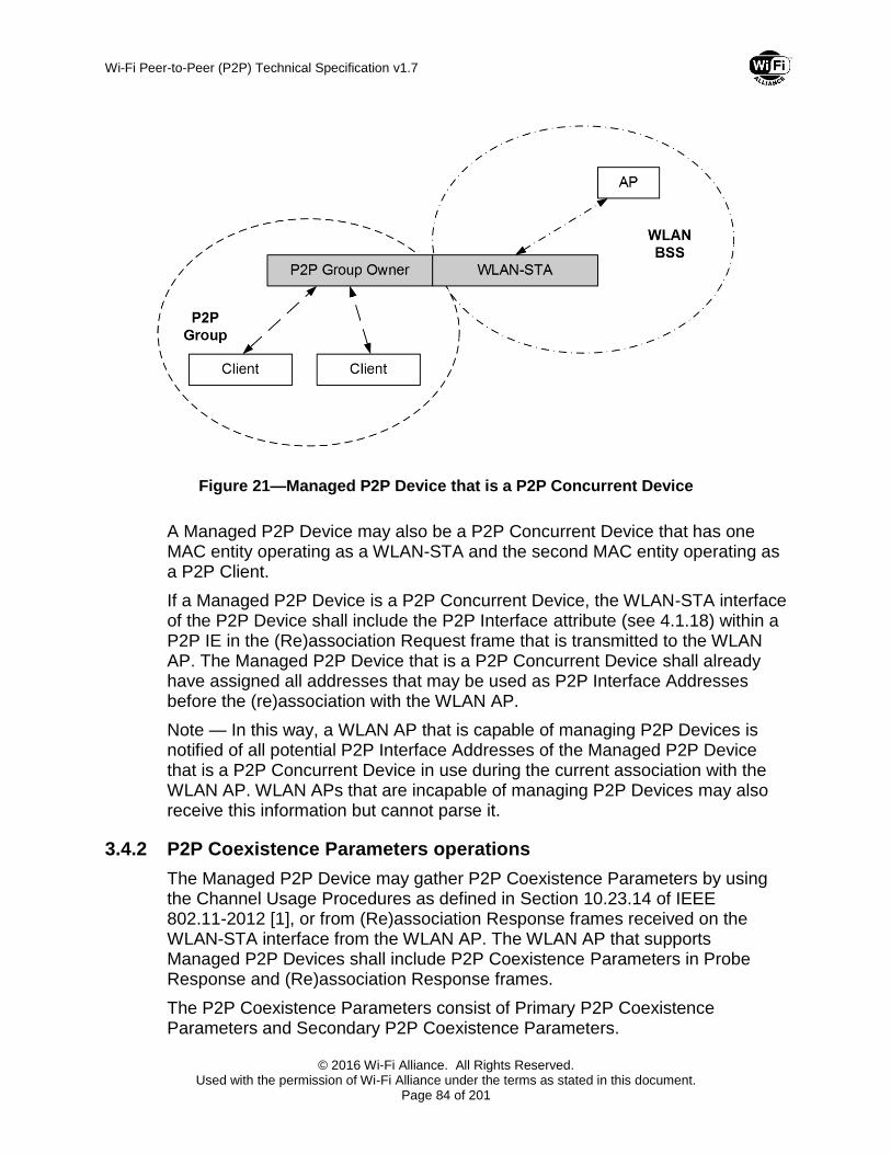
Wi-Fi Peer-to-Peer (P2P) Technical Specification v1.7
© 2016 Wi-Fi Alliance. All Rights Reserved. Used with the permission of Wi-Fi Alliance under the terms as stated in this document.
Page 84 of 201
Figure 21—Managed P2P Device that is a P2P Concurrent Device
A Managed P2P Device may also be a P2P Concurrent Device that has one MAC entity operating as a WLAN-STA and the second MAC entity operating as a P2P Client.
If a Managed P2P Device is a P2P Concurrent Device, the WLAN-STA interface of the P2P Device shall include the P2P Interface attribute (see 4.1.18) within a P2P IE in the (Re)association Request frame that is transmitted to the WLAN AP. The Managed P2P Device that is a P2P Concurrent Device shall already have assigned all addresses that may be used as P2P Interface Addresses before the (re)association with the WLAN AP.
Note — In this way, a WLAN AP that is capable of managing P2P Devices is notified of all potential P2P Interface Addresses of the Managed P2P Device that is a P2P Concurrent Device in use during the current association with the WLAN AP. WLAN APs that are incapable of managing P2P Devices may also receive this information but cannot parse it.
3.4.2 P2P Coexistence Parameters operations
The Managed P2P Device may gather P2P Coexistence Parameters by using the Channel Usage Procedures as defined in Section 10.23.14 of IEEE 802.11-2012 [1], or from (Re)association Response frames received on the WLAN-STA interface from the WLAN AP. The WLAN AP that supports Managed P2P Devices shall include P2P Coexistence Parameters in Probe Response and (Re)association Response frames.
The P2P Coexistence Parameters consist of Primary P2P Coexistence Parameters and Secondary P2P Coexistence Parameters.

Wi-Fi Peer-to-Peer (P2P) Technical Specification v1.7
© 2016 Wi-Fi Alliance. All Rights Reserved. Used with the permission of Wi-Fi Alliance under the terms as stated in this document.
Page 85 of 201
The Primary P2P Coexistence Parameters contain Channel Usage information that may be used by IT departments to optimize P2P Devices within the IT defined channel mappings assigned to IT controlled APs. The Managed P2P Device that is a P2P Concurrent Device should use Primary P2P Coexistence Parameters as part of channel selection processing to start a P2P Group. If the P2P Group is already started or the Managed P2P Device is not a P2P Concurrent Device, the Primary P2P Coexistence Parameters may be used by the Managed P2P Device to initiate a channel switch or as part of channel selection processing respectively.
The Secondary P2P Coexistence Parameters consist of P2P Client specific parameters such as maximum transmit power (via the Country and Power Constraint elements) and WMM Parameter Element. The Secondary P2P Coexistence Parameters are used to allow Enterprise IT to give WLAN and P2P Devices the same access priority to the medium. The Managed P2P Device that is a P2P Group Owner may use the Secondary P2P Coexistence Parameters as part of determining its maximum transmit power and WMM Parameters Elements for P2P Clients. If the P2P Group Owner is a P2P Concurrent Device in which the P2P Group operates at the same channel with the WLAN BSS, the P2P Group Owner should use the Secondary P2P Coexistence Parameters as part of determining its maximum transmit power and WMM Parameters Elements for P2P Clients. The P2P Group Owner may also set its maximum transmit power and WMM Parameters Elements based on local device decisions that trade off the Enterprise IT benefits and P2P Group benefits. For example, a public printer benefits from longer range more so than a conference room projector; thus, the transmit power may not be the same for the two devices.
The normative behaviors of a P2P Group Owner setting P2P Coexistence Parameters are shown in Table 2.
Table 2—P2P Coexistence Parameters setting
Device Configuration Primary P2P Coexistence Parameters
Secondary P2P Coexistence Parameters
New Group Existing Group
Managed P2P Device that is a P2P Concurrent Device
Recommended Optional Recommended for a P2P Group that operates in the same channel with the WLAN BSS, and optional otherwise
Managed P2P Device that is not a P2P Concurrent Device
Optional Optional Optional
In general, application of the P2P Coexistence Parameters to a P2P Group is a device implementation decision. However:
A P2P Concurrent Device that is a Managed P2P Device shall adopt the Primary P2P Coexistence Parameters and recommended (see Table 2)

Wi-Fi Peer-to-Peer (P2P) Technical Specification v1.7
© 2016 Wi-Fi Alliance. All Rights Reserved. Used with the permission of Wi-Fi Alliance under the terms as stated in this document.
Page 86 of 201
Secondary P2P Coexistence Parameters while associated to a WLAN AP that advertises Coexistence Optional set to 0, if the Primary P2P Coexistence Parameters include the WLAN AP’s serving channel.
A P2P Concurrent Device that is a Managed P2P Device should adopt the Primary P2P Coexistence Parameters while associated to a WLAN AP that advertises Coexistence Optional set to 0 if (1) the P2P Device is capable of concurrently operating in a WLAN BSS and a P2P Group that are each operating on different bands and (2) the Primary P2P Coexistence Parameters include a channel on a different band than the WLAN AP’s serving channel.
The Enterprise IT department may not allow Concurrent P2P Devices to connect to the WLAN infrastructure if these devices do not adhere to these P2P Coexistence Parameters.
A P2P Client that is a Managed P2P Device does not use the P2P Coexistence Parameters since the Operating Class, Channel and Secondary P2P Coexistence Parameters adopted by a P2P Group are chosen by the P2P Group Owner.
3.4.3 WLAN Deauthentication/Disassociation
If a WLAN Infrastructure determines that a P2P Managed Device is a P2P Concurrent Device operating with cross connection enabled, the AP may deauthenticate or disassociate the WLAN STA. The WLAN infrastructure may determine that cross-connection is enabled by the P2P Device setting the Cross Connection bit in the Group Capability Bitmap field of the P2P Capability attribute (see Section 4.1.4) to 1, or via other means. The Deauthenticate or Disassociate frame shall include the P2P IE with the Minor Reason Code field set to 1 in the Minor Reason Code attribute (see Section 4.1.3). This action may be taken independent of the setting of the P2P Infrastructure Managed bit in the Device Capability Bitmap field of the P2P Capability attribute.
Note — It is advisable that a P2P Device deauthenticated or disassociated with a Minor Reason Code set to 1 not attempt to (re)associate to the WLAN AP:
while cross connection is enabled at the P2P Device and the WLAN AP sets Cross Connection Permitted to 0 in the P2P Manageability attribute in the P2P IE in transmitted Beacons, DMG Beacons (if the P2P IE is present in the frame), Announce, and Probe Response frames, or
until P2P Device capability is disabled.
If a WLAN Infrastructure determines that a P2P Concurrent Device is using P2P Coexistence Parameters in any fashion that does not meet IT defined policy, the AP may deauthenticate or disassociate the STA. The Deauthenticate or Disassociate frame shall include the P2P IE with the Minor Reason Code field set to 3 in the Minor Reason Code attribute (see Section 4.1.3).
Note — It is advisable that a P2P Device deauthenticated or disassociated with a Minor Reason Code set to 3 not attempt to (re)associate to the WLAN until:

Wi-Fi Peer-to-Peer (P2P) Technical Specification v1.7
© 2016 Wi-Fi Alliance. All Rights Reserved. Used with the permission of Wi-Fi Alliance under the terms as stated in this document.
Page 87 of 201
the P2P Device has more closely adopted the Primary P2P Coexistence Parameters and Secondary P2P Coexistence Parameters (see Section 3.4.2) while the WLAN AP sets Coexistence Optional to 0 in the P2P Manageability attribute in the P2P IE in transmitted Beacons, DMG Beacons (if the P2P IE is present in the frame), Announce, and Probe Response frames, or
P2P Device capability is disabled.
If a WLAN Infrastructure receives an Association Request frame from a P2P Concurrent Device that contains a P2P Capability attribute (see Section 4.1.4) with the Infrastructure Managed bit set to 1, the AP may deauthenticate or disassociate the WLAN STA if P2P operation is outside the IT defined policy. The Deauthenticate or Disassociate frame shall include the P2P IE with the Minor Reason Code field set to 4 in the Minor Reason Code attribute (see Section 4.1.3).
Note — It is advisable that a P2P Device deauthenticated or disassociated with a Minor Reason Code set to 4 not attempt to (re)associate to the WLAN AP until:
the P2P Device expects that the WLAN AP permissions could have changed, or
P2P Device capability is disabled.
Note — The P2P Device may attempt to re-associate to the WLAN Infrastructure with P2P Device capability disabled. Disabling P2P Device capability includes omitting the P2P IE from all Management frames, leaving all P2P Groups and not responding to Invitation Requests.
3.4.4 Managed P2P Device Summary
Requirements for different P2P Device states are summarized in Table 3.
Table 3—Summary of requirements on Managed P2P Devices
Managed P2P Device
P2P Group Owner or P2P
Client
Concurrent P2P Device
Requirements
No P2P Client Any Sets Infrastructure Managed bit to 0.
Understands Minor Reason Code set to 2.
Alternatively, the P2P Device can disable P2P Device capability before (Re)associating to the WLAN.
No P2P Group Owner
No Sets Infrastructure Managed bit to 0.
Understands Minor Reason Code set to 2.
Alternatively, the P2P Device can disable P2P Device capability before (Re)associating to the WLAN.

Wi-Fi Peer-to-Peer (P2P) Technical Specification v1.7
© 2016 Wi-Fi Alliance. All Rights Reserved. Used with the permission of Wi-Fi Alliance under the terms as stated in this document.
Page 88 of 201
Managed P2P Device
P2P Group Owner or P2P
Client
Concurrent P2P Device
Requirements
No P2P Group Owner
Yes Sets Infrastructure Managed bit to 0.
Understands Minor Reason Code set to 1 or 2.
Shall not enable cross connection while associated to a WLAN AP that advertises a P2P Manageability attribute with Cross Connection Permitted set to 0.
Alternatively, the P2P Device can disable P2P Device capability before (Re)associating to the WLAN.
Yes P2P Client No Sets Infrastructure Managed bit to 1.
Sets Cross Connection bit to 0.
Understands all values of Minor Reason Code.
Yes P2P Client Yes Sets Infrastructure Managed bit to 1.
Sets Cross Connection bit to 0.
Includes P2P Interface attribute in (Re)association Request.
Understands all values of Minor Reason Code.
Yes P2P Group Owner
No Sets Infrastructure Managed bit to 1.
Sets Cross Connection bit to 0.
Uses Primary P2P Coexistence Parameters and Secondary P2P Coexistence Parameters as per Section 3.4.2.
Understands all values of Minor Reason Code.
Yes P2P Group Owner
Yes Sets Infrastructure Managed bit to 1.
Sets Cross Connection bit to 0 or 1.
Includes P2P Interface attribute in (Re)association Request.
Shall not enable cross connection while associated to a WLAN AP that advertises a P2P Manageability attribute with Cross Connection Permitted set to 0.
Uses Primary P2P Coexistence Parameters and Secondary P2P Coexistence Parameters as per Section 3.4.2.
Understands all values of Minor Reason Code.

Wi-Fi Peer-to-Peer (P2P) Technical Specification v1.7
© 2016 Wi-Fi Alliance. All Rights Reserved. Used with the permission of Wi-Fi Alliance under the terms as stated in this document.
Page 89 of 201
4 Frame formats
This section describes the information elements (see Section 4.1) and frame formats (see Section 4.2) in support of the capabilities described in clause P2P specific functions and services (see Section 2.4).
P2P protocol communication is based on the use of P2P Information Element (P2P IE), P2P Action frame and P2P Public Action frame formats. These utilize the Vendor Specific Information Element and Vendor Specific Action frame formats in IEEE 802.11-2012 [1] for operation outside DMG and in IEEE 802.11-REVmc [11] for operation within DMG, with the Wi-Fi Alliance OUI and an OUI Type indicating P2P. A number of P2P attributes are defined; a single P2P IE carries one or more P2P attributes.
A P2P Device shall be able to properly construct a subset of the frames specified in this clause for transmission and to decode a (potentially different) subset of the frames specified in this clause upon validation following reception. The particular subset of these frames that a P2P Device constructs and decodes is determined by the functions and roles supported by that P2P Device, as specified in Section 4.3.
4.1 P2P Information Element
4.1.1 P2P IE format
The Vendor Specific information element format (as defined in IEEE 802.11-2012 [1] for operation outside DMG and in IEEE 802.11-REVmc [11] for operation within DMG) is used to define the P2P information element (P2P IE) in this specification. The format of the P2P IE is shown in Table 4.
Table 4—P2P IE format
Field Size
(octets) Value
(Hexadecimal) Description
Element ID 1 0xDD IEEE 802.11 vendor specific usage.
Length 1 variable Length of the following fields in the IE in octets. The Length field is a variable, and set to 4 plus the total length of P2P attributes.
OUI 3 50 6F 9A Wi-Fi Alliance specific OUI.
OUI Type 1 0x09 (to be assigned)
Identifying the type or version of P2P IE.
Setting to 0x09 indicates Wi-Fi Alliance P2P v1.0.
P2P Attributes variable One of more P2P attributes appear in the P2P IE.

Wi-Fi Peer-to-Peer (P2P) Technical Specification v1.7
© 2016 Wi-Fi Alliance. All Rights Reserved. Used with the permission of Wi-Fi Alliance under the terms as stated in this document.
Page 90 of 201
The P2P attributes are defined to have a common general format consisting of a 1 octet P2P Attribute ID field, a 2 octet Length field and variable-length attribute-specific information fields, as shown in Table 5.
Table 5—General format of P2P attribute
Field Size
(octets) Value
(Hexadecimal) Description
Attribute ID 1 variable Identifying the type of P2P attribute. The specific value is defined in Table 6.
Length 2 variable Length of the following fields in the attribute.
Attributes body field
variable Attribute-specific information fields.
Table 6—P2P Attribute ID definitions
Attribute ID Notes
0 Status
1 Minor Reason Code
2 P2P Capability
3 P2P Device ID
4 Group Owner Intent
5 Configuration Timeout
6 Listen Channel
7 P2P Group BSSID
8 Extended Listen Timing
9 Intended P2P Interface Address
10 P2P Manageability
11 Channel List
12 Notice of Absence
13 P2P Device Info
14 P2P Group Info
15 P2P Group ID
16 P2P Interface
17 Operating Channel
18 Invitation Flags
19 Out-of-Band Group Owner Negotiation

Wi-Fi Peer-to-Peer (P2P) Technical Specification v1.7
© 2016 Wi-Fi Alliance. All Rights Reserved. Used with the permission of Wi-Fi Alliance under the terms as stated in this document.
Page 91 of 201
Attribute ID Notes
Channel
20 Unused *
21 Service Hash
22 Session Information Data Info
23 Connection Capability Info
24 Advertisement_ID Info
25 Advertised Service Info
26 Session ID Info
27 Feature Capability
28 Persistent Group Info
29 – 220 Reserved
221 Vendor specific attribute
222 – 255 Reserved
* Unused means this is not available ever to be used.
A P2P Device that encounters an unknown or reserved Attribute ID value in a P2P IE received without error shall ignore that P2P attribute and parse any remaining fields for additional P2P attributes with recognizable Attribute ID values. A P2P Device that encounters a recognizable but unexpected Attribute ID value in the received P2P IE may ignore that P2P attribute.
More than one P2P IE may be included in a single frame. If multiple P2P IEs are present, the complete P2P attribute data consists of the concatenation of the P2P Attribute fields of the P2P IEs. The P2P Attributes field of each P2P IE may be any length up to the maximum (251 octets). The order of the concatenated P2P attribute data shall be preserved in the ordering of the P2P IEs in the frame. All of the P2P IEs shall fit within a single frame and shall be adjacent in the frame. Where a P2P attribute is not contained entirely within a single P2P IE, the P2P Attribute ID and Length fields for that attribute occur only once at the start. Figure 22 illustrates an example where three P2P attributes are carried in two P2P IEs, with the second attribute spanning the P2P IEs.
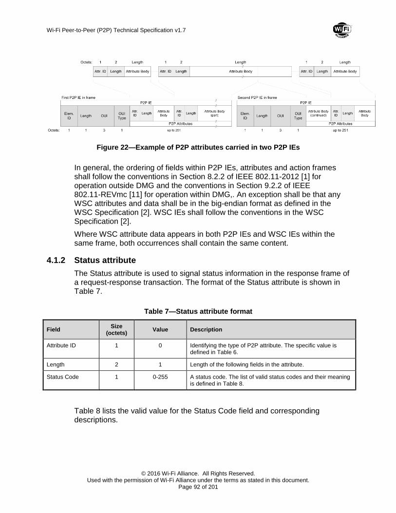
Wi-Fi Peer-to-Peer (P2P) Technical Specification v1.7
© 2016 Wi-Fi Alliance. All Rights Reserved. Used with the permission of Wi-Fi Alliance under the terms as stated in this document.
Page 92 of 201
Figure 22—Example of P2P attributes carried in two P2P IEs
In general, the ordering of fields within P2P IEs, attributes and action frames shall follow the conventions in Section 8.2.2 of IEEE 802.11-2012 [1] for operation outside DMG and the conventions in Section 9.2.2 of IEEE 802.11-REVmc [11] for operation within DMG,. An exception shall be that any WSC attributes and data shall be in the big-endian format as defined in the WSC Specification [2]. WSC IEs shall follow the conventions in the WSC Specification [2].
Where WSC attribute data appears in both P2P IEs and WSC IEs within the same frame, both occurrences shall contain the same content.
4.1.2 Status attribute
The Status attribute is used to signal status information in the response frame of a request-response transaction. The format of the Status attribute is shown in Table 7.
Table 7—Status attribute format
Field Size
(octets) Value Description
Attribute ID 1 0 Identifying the type of P2P attribute. The specific value is defined in Table 6.
Length 2 1 Length of the following fields in the attribute.
Status Code 1 0-255 A status code. The list of valid status codes and their meaning is defined in Table 8.
Table 8 lists the valid value for the Status Code field and corresponding descriptions.
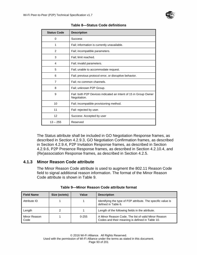
Wi-Fi Peer-to-Peer (P2P) Technical Specification v1.7
© 2016 Wi-Fi Alliance. All Rights Reserved. Used with the permission of Wi-Fi Alliance under the terms as stated in this document.
Page 93 of 201
Table 8—Status Code definitions
Status Code Description
0 Success
1 Fail; information is currently unavailable.
2 Fail; incompatible parameters.
3 Fail; limit reached.
4 Fail; invalid parameters.
5 Fail; unable to accommodate request.
6 Fail; previous protocol error, or disruptive behavior.
7 Fail; no common channels.
8 Fail; unknown P2P Group.
9 Fail: both P2P Devices indicated an Intent of 15 in Group Owner Negotiation.
10 Fail; incompatible provisioning method.
11 Fail: rejected by user.
12 Success: Accepted by user
13 – 255 Reserved
The Status attribute shall be included in GO Negotiation Response frames, as described in Section 4.2.9.3, GO Negotiation Confirmation frames, as described in Section 4.2.9.4, P2P Invitation Response frames, as described in Section 4.2.9.6, P2P Presence Response frames, as described in Section 4.2.10.4, and (Re)association Response frames, as described in Section 4.2.5.
4.1.3 Minor Reason Code attribute
The Minor Reason Code attribute is used to augment the 802.11 Reason Code field to signal additional reason information. The format of the Minor Reason Code attribute is shown in Table 9.
Table 9—Minor Reason Code attribute format
Field Name Size (octets) Value Description
Attribute ID 1 1 Identifying the type of P2P attribute. The specific value is defined in Table 6.
Length 2 1 Length of the following fields in the attribute.
Minor Reason Code
1 0-255 A Minor Reason Code. The list of valid Minor Reason Codes and their meaning is defined in Table 10.

Wi-Fi Peer-to-Peer (P2P) Technical Specification v1.7
© 2016 Wi-Fi Alliance. All Rights Reserved. Used with the permission of Wi-Fi Alliance under the terms as stated in this document.
Page 94 of 201
Table 10 lists the valid values for the Minor Reason Code field and corresponding descriptions.
Table 10—Minor Reason Code definitions
Minor Reason Code
Description
0 Reserved
1 Disassociated/deauthenticated from the WLAN AP because the Cross Connection capability bit is 1 and this capability within this device is outside the IT defined policy. Note: this may be the returned reason code independent of the value of the P2P Infrastructure Managed capability setting.
2 Disassociated/deauthenticated from the WLAN AP because the P2P Infrastructure Managed bit is 0.
3 Disassociated/deauthenticated from the WLAN because a P2P Concurrent Device is not setting P2P Coexistence Parameters within the IT defined policy; this applies to either primary or secondary P2P Coexistence Parameters.
4 Disassociated/deauthenticated from the WLAN AP because the P2P Device has included the P2P IE with the P2P Infrastructure Managed bit set to 1 and P2P operation within this device is outside the IT defined policy.
5-255 Reserved.
The inclusion of the Minor Reason Code attribute in Deauthentication and Disassociation frames by the WLAN infrastructure is described in Section 3.4.3.
4.1.4 P2P Capability attribute
The P2P Capability attribute contains a set of parameters that can be used to establish a P2P connection. The format of the P2P Capability attribute is shown in Table 11.
Table 11—P2P Capability attribute format
Field Size
(octets) Value Description
Attribute ID 1 2 Identifying the type of P2P attribute. The specific value is defined in Table 6.
Length 2 2 Length of the following fields in the attribute.
Device Capability Bitmap
1 variable A set of parameters indicating P2P Device’s capabilities, as defined in Table 12.
Group Capability Bitmap
1 variable A set of parameters indicating the current state of a P2P Group, as defined in Table 13.

Wi-Fi Peer-to-Peer (P2P) Technical Specification v1.7
© 2016 Wi-Fi Alliance. All Rights Reserved. Used with the permission of Wi-Fi Alliance under the terms as stated in this document.
Page 95 of 201
The format of the Device Capability Bitmap field is described in Table 12.
Table 12—Device Capability Bitmap definition
Bit(s) Information Notes
0 Service Discovery
The Service Discovery field shall be set to 1 if the P2P Device supports Service Discovery, and is set to 0 otherwise.
1 P2P Client Discoverability
Within a P2P Group Info attribute and a (Re)association request frame the P2P Client Discoverability field shall be set to 1 when the P2P Device supports P2P Client Discoverability, and is set to 0 otherwise. This field shall be reserved and set to 0 in all other frames or uses.
2 Concurrent Operation
The Concurrent Operation field shall be set to 1 when the P2P Device supports Concurrent Operation with WLAN, and is set to 0 otherwise.
3 P2P Infrastructure Managed
The P2P Infrastructure Managed field shall be set to 1 when the P2P interface of the P2P Device is capable of being managed by the WLAN (infrastructure network) based on P2P Coexistence Parameters, and set to 0 otherwise.
4 P2P Device Limit The P2P Device Limit field shall be set to 1 when the P2P Device is unable to participate in additional P2P Groups, and set to 0 otherwise.
5 P2P Invitation Procedure
The P2P Invitation Procedure field shall be set to 1 if the P2P Device is capable of processing P2P Invitation Procedure signaling, and set to 0 otherwise.
6 – 7 Reserved —
The format of the Group Capability Bitmap field is described in Table 13.
Table 13—Group Capability Bitmap definition
Bit(s) Information Notes
0 P2P Group Owner
The P2P Group Owner field shall be set to 1 when the P2P Device is operating as a Group Owner, and set to 0 otherwise.
1 Persistent P2P Group
The Persistent P2P Group field shall be set to 1 when the P2P Device is hosting, or intends to host, a P2P Persistent Group, and set to 0 otherwise.
2 P2P Group Limit The P2P Group Limit field shall be set to 1 when the P2P Group Owner is unable to add additional Clients to its P2P Group, and set to 0 otherwise.

Wi-Fi Peer-to-Peer (P2P) Technical Specification v1.7
© 2016 Wi-Fi Alliance. All Rights Reserved. Used with the permission of Wi-Fi Alliance under the terms as stated in this document.
Page 96 of 201
Bit(s) Information Notes
3 Intra-BSS Distribution
The Intra-BSS Distribution field shall be set to 1 if the P2P Device is hosting, or intends to host, a P2P Group that provides a data distribution service between Clients in the P2P Group. The Intra-BSS Distribution field shall be set to 0, if the P2P Device is not a P2P Group Owner, or is not providing such a data distribution service.
Note — When operating within DMG, the optional data distribution service is provided through the PCP forwarding mechanism using A-MSDUs as described in Section 10.12 of IEEE 802.11-REVmc [11].
4 Cross Connection
The Cross Connection field shall be set to 1 if the P2P Device is hosting, or intends to host, a P2P Group that provides cross connection between the P2P Group and a WLAN. The Cross Connection field shall be set to 0 if the P2P Device is not a P2P Group Owner, or is not providing a cross connection service.
5 Persistent Reconnect
The Persistent Reconnect field shall be set to 1 when the P2P Device is hosting, or intends to host, a persistent P2P Group that allows reconnection without user intervention, and set to 0 otherwise.
6 Group Formation The Group Formation field shall be set to 1 when the P2P Device is operating as a Group Owner in the Provisioning phase of Group Formation, and set to 0 otherwise.
7 IP Address Allocation
The IP Address Allocation field shall be set to 1 if the P2P Device is operating as a Group Owner and supports IP Address Allocation in EAPOL key frames defined in 4.2.8.
The P2P Capability attribute shall be included in Beacon frames, as described in Section 4.2.1, Probe Request frames, as described in Section 4.2.2, Probe Response frames, as described in Section 4.2.3, GO Negotiation Request frames, as described in Section 4.2.9.2, GO Negotiation Response frames, as described in Section 4.2.9.3, GO Negotiation Confirmation frames, as described in Section 4.2.9.4, (Re)association Request frames, as described in Section 4.2.4, Announce frames as described in Section 4.3.1, and Provision Discovery Request frames, as described in Section 4.2.9.9. In addition, the P2P Capability attribute may be included in DMG Beacon frames as described in Section 4.3.1.The Group Capability Bitmap field in the P2P Capability attribute shall be reserved in Probe Request frames, and in Probe Response frames that are transmitted by a P2P Device that is not a Group Owner. The Group Capability Bitmap field in the P2P Capability attribute is used when associating with a WLAN AP that includes P2P IE in Beacon, DMG Beacon (if the P2P IE is present in the frame), Announce, and Probe Response frames; otherwise, it shall be reserved when the P2P Capability attribute is included in the (Re)association Request frames. The use of the P2P Capability attribute is described in Section 3.1.2.

Wi-Fi Peer-to-Peer (P2P) Technical Specification v1.7
© 2016 Wi-Fi Alliance. All Rights Reserved. Used with the permission of Wi-Fi Alliance under the terms as stated in this document.
Page 97 of 201
4.1.5 P2P Device ID attribute
The P2P Device ID attribute contains P2P Device Address. The format of the P2P Device ID attribute is shown in Table 14.
Table 14—P2P Device ID attribute format
Field Name Size (octets) Value Description
Attribute ID 1 3 Identifying the type of P2P attribute. The specific value is defined in Table 6.
Length 2 6 Length of the following fields in the attribute.
P2P Device Address
6 — An identifier used to uniquely reference a P2P Device.
The P2P Device ID attribute shall be present in the P2P IE in the Beacon frame, as described in Section 4.2.1, in the DMG Beacon frame (if the P2P IE is present in the frame), as described in Section 4.3.1, in the Announce frame, as described in Section 4.3.1, and in the Device Discoverability Request frame, as described in Section 4.2.9.7.
4.1.6 Group Owner Intent attribute
The Group Owner Intent attribute contains intent value of a P2P Device’s willingness of being the P2P Group Owner. The format of the Group Owner Intent attribute is shown in Table 15.
Table 15—Group Owner Intent attribute format
Field Size
(octets) Value Description
Attribute ID 1 4 Identifying the type of P2P attribute. The specific value is defined in Table 6.
Length 2 1 Length of the following fields in the attribute.
GO Intent 1 variable Information that is used to decide which P2P Device will be the P2P Group Owner. See Table 16.
The Group Owner Intent attribute shall be included in GO Negotiation Request frames, as described in Section 4.2.9.2, and GO Negotiation Response frames, as described in Section 4.2.9.3. The use of the Group Owner Intent attribute is described in Section 3.1.4.
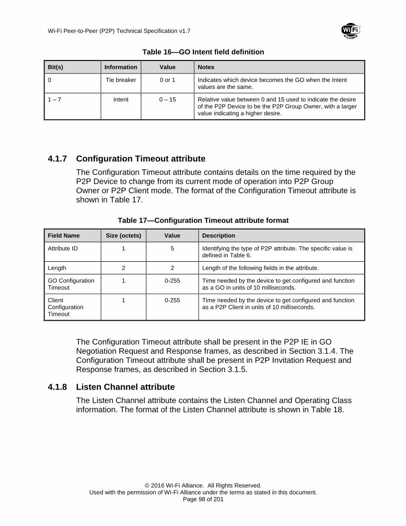
Wi-Fi Peer-to-Peer (P2P) Technical Specification v1.7
© 2016 Wi-Fi Alliance. All Rights Reserved. Used with the permission of Wi-Fi Alliance under the terms as stated in this document.
Page 98 of 201
Table 16—GO Intent field definition
Bit(s) Information Value Notes
0 Tie breaker 0 or 1 Indicates which device becomes the GO when the Intent values are the same.
1 – 7 Intent 0 – 15 Relative value between 0 and 15 used to indicate the desire of the P2P Device to be the P2P Group Owner, with a larger value indicating a higher desire.
4.1.7 Configuration Timeout attribute
The Configuration Timeout attribute contains details on the time required by the P2P Device to change from its current mode of operation into P2P Group Owner or P2P Client mode. The format of the Configuration Timeout attribute is shown in Table 17.
Table 17—Configuration Timeout attribute format
Field Name Size (octets) Value Description
Attribute ID 1 5 Identifying the type of P2P attribute. The specific value is defined in Table 6.
Length 2 2 Length of the following fields in the attribute.
GO Configuration Timeout
1 0-255 Time needed by the device to get configured and function as a GO in units of 10 milliseconds.
Client Configuration Timeout
1 0-255 Time needed by the device to get configured and function as a P2P Client in units of 10 milliseconds.
The Configuration Timeout attribute shall be present in the P2P IE in GO Negotiation Request and Response frames, as described in Section 3.1.4. The Configuration Timeout attribute shall be present in P2P Invitation Request and Response frames, as described in Section 3.1.5.
4.1.8 Listen Channel attribute
The Listen Channel attribute contains the Listen Channel and Operating Class information. The format of the Listen Channel attribute is shown in Table 18.
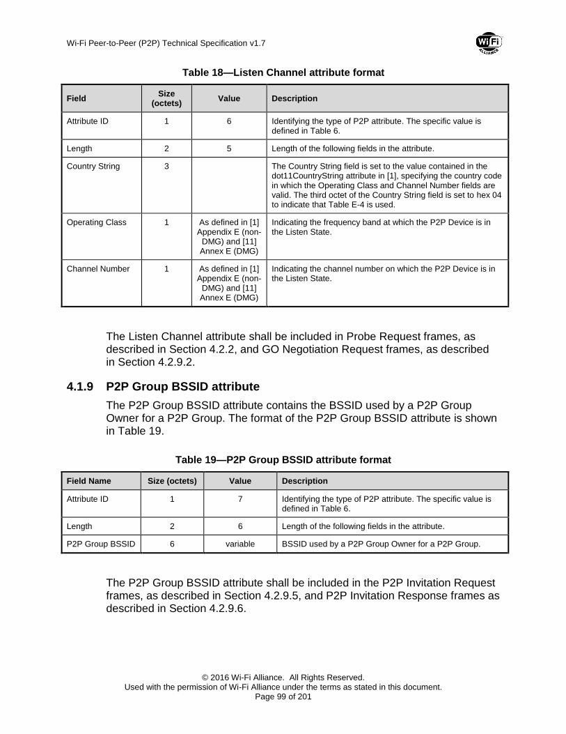
Wi-Fi Peer-to-Peer (P2P) Technical Specification v1.7
© 2016 Wi-Fi Alliance. All Rights Reserved. Used with the permission of Wi-Fi Alliance under the terms as stated in this document.
Page 99 of 201
Table 18—Listen Channel attribute format
Field Size
(octets) Value Description
Attribute ID 1 6 Identifying the type of P2P attribute. The specific value is defined in Table 6.
Length 2 5 Length of the following fields in the attribute.
Country String 3 The Country String field is set to the value contained in the dot11CountryString attribute in [1], specifying the country code in which the Operating Class and Channel Number fields are valid. The third octet of the Country String field is set to hex 04 to indicate that Table E-4 is used.
Operating Class 1 As defined in [1] Appendix E (non-
DMG) and [11] Annex E (DMG)
Indicating the frequency band at which the P2P Device is in the Listen State.
Channel Number 1 As defined in [1] Appendix E (non-
DMG) and [11] Annex E (DMG)
Indicating the channel number on which the P2P Device is in the Listen State.
The Listen Channel attribute shall be included in Probe Request frames, as described in Section 4.2.2, and GO Negotiation Request frames, as described in Section 4.2.9.2.
4.1.9 P2P Group BSSID attribute
The P2P Group BSSID attribute contains the BSSID used by a P2P Group Owner for a P2P Group. The format of the P2P Group BSSID attribute is shown in Table 19.
Table 19—P2P Group BSSID attribute format
Field Name Size (octets) Value Description
Attribute ID 1 7 Identifying the type of P2P attribute. The specific value is defined in Table 6.
Length 2 6 Length of the following fields in the attribute.
P2P Group BSSID 6 variable BSSID used by a P2P Group Owner for a P2P Group.
The P2P Group BSSID attribute shall be included in the P2P Invitation Request frames, as described in Section 4.2.9.5, and P2P Invitation Response frames as described in Section 4.2.9.6.

Wi-Fi Peer-to-Peer (P2P) Technical Specification v1.7
© 2016 Wi-Fi Alliance. All Rights Reserved. Used with the permission of Wi-Fi Alliance under the terms as stated in this document.
Page 100 of 201
4.1.10 Extended Listen Timing attribute
The Extended Listen Timing attribute may be used by a P2P Device to communicate the Listen State availability timing it uses in a discoverable state. A P2P Device may also use the Extended Listen Timing Element to suggest a desirable Listen State Timing to a P2P Device that is a P2P Group Owner for a Persistent P2P Group. The format of the Extended Listen Timing attribute is shown in Table 20.
Table 20—Extended Listen Timing attribute format
Field Name Size (octets) Value Description
Attribute ID 1 8 Identifying the type of P2P attribute. The specific value is defined in Table 6.
Length 2 4 Length of the following fields in the attribute.
Availability Period 2 1-65535 The minimum period of continuous availability in Listen State in milliseconds. Availability Period shall be reserved and set to 0 in (Re)association Request frames. See note.
Availability Interval 2 1-65535 The interval between the start of periods of continuous availability in Listen State in units of milliseconds. See note.
Note — A P2P Device using the Extended Listen Timing attribute to communicate that it is continuously available (in Listen State) shall set both Availability Period and Availability Interval to 65535.
The Extended Listen Timing attribute may be present in the P2P IE in Probe Request, Probe Response, GO Negotiation Request and (Re)Association Response frames transmitted by a P2P Device to indicate the Extended Listen Timing of the P2P Device. The Extended Listen Timing attribute may be present in the P2P IE in (Re)association Request frames transmitted by a P2P Device to indicate the Extended Listen Timing desired of a Persistent P2P Group Owner.
4.1.11 Intended P2P Interface Address attribute
The Intended P2P Interface Address attribute contains the P2P Interface Device a P2P Device intends to use in a P2P Group. The format of the Intended P2P Interface Address attribute is shown in Table 21.
Table 21—Intended P2P Interface Address attribute format
Field Name Size (octets) Value Description
Attribute ID 1 9 Identifying the type of P2P attribute. The specific value is defined in Table 6.
Length 2 6 Length of the following fields in the attribute.

Wi-Fi Peer-to-Peer (P2P) Technical Specification v1.7
© 2016 Wi-Fi Alliance. All Rights Reserved. Used with the permission of Wi-Fi Alliance under the terms as stated in this document.
Page 101 of 201
Field Name Size (octets) Value Description
P2P Interface Address
6 variable P2P Interface Address intended to be used in a P2P Group.
The Intended P2P Interface Address attribute shall be present in the P2P IE in GO Negotiation Request and Response frames, as described in Section 3.1.4.
4.1.12 P2P Manageability attribute
The P2P Manageability attribute contains infrastructure manageability information from the WLAN AP to a scanning or associating WLAN STA, which may or may not be a P2P Device. The format of the P2P Manageability attribute is shown in Table 22.
Table 22—P2P Manageability attribute format
Field Name Size (octets) Value Description
Attribute ID 1 10 Identifying the type of P2P attribute. The specific value is defined in Table 6.
Length 2 1 Length of the following fields in the attribute.
Manageability Bitmap field
1 See Table 23 Identifying the WLAN AP’s P2P Manageability.
Table 23—Manageability Bitmap field format
Bit Description
B0 P2P Device Management
B1 Cross Connection Permitted
B2 Coexistence Optional
B3–B7 Reserved
The P2P Device Management field set to 1 indicates that the WLAN AP supports Managed P2P Device. The P2P Device Management field set to 0 indicates that the WLAN has no desire to manage P2P Devices.
The Cross Connection Permitted field set to 1 indicates that the WLAN AP permits P2P Concurrent Devices to offer cross connection. The Cross Connection Permitted field set to 0 indicates that the WLAN AP does not permit P2P Devices that the WLAN AP determines are P2P Concurrent Devices to offer cross connection. See Section 3.4.3.

Wi-Fi Peer-to-Peer (P2P) Technical Specification v1.7
© 2016 Wi-Fi Alliance. All Rights Reserved. Used with the permission of Wi-Fi Alliance under the terms as stated in this document.
Page 102 of 201
The Coexistence Optional field set to 1 indicates that the Primary P2P Coexistence Parameters and recommended (see Table 2) Secondary P2P Coexistence Parameters advertised by the WLAN AP are not required. The Coexistence Optional field set to 0 indicates that the Primary P2P Coexistence Parameters and recommended Secondary P2P Coexistence Parameters advertised by the WLAN AP are required for P2P Devices that the WLAN AP determines are P2P Concurrent Devices in order to remain associated to the WLAN. See Section 3.4.3.
The P2P Manageability attribute shall be included in Beacon, Announce, Probe Response, and (Re)association Response frames that are transmitted by the WLAN AP as described in Section 3.4.1. The P2P Manageability attribute may be included in DMG Beacon frames that are transmitted by the WLAN AP as described in 3.4.1.
4.1.13 Channel List attribute
The Channel List attribute contains a list of Operating Class and Channel pair information. The format of the Channel List attribute is shown in Table 24.
Table 24—Channel List attribute format
Field Size
(octets) Value Description
Attribute ID 1 11 Identifying the type of P2P attribute. The specific value is defined in Table 6.
Length 2 variable Length of the following fields in the attribute.
Country String 3 The Country String field is set to the value contained in the dot11CountryString attribute in [1], specifying the country code in which the Channel Entry List is valid. The third octet of the Country String field is set to hex 04 to indicate that Table E-4 is used.
Channel Entry List variable Including one or more Channel Entries. The format of Channel Entry field is shown in Table 25.
Table 25—Channel Entry field format
Field Size
(octets) Value Description
Operating Class 1 As defined in [1] Appendix E (non-
DMG) and [11] Annex E (DMG)
The Operating Class field contains an enumerated value from Appendix E [1] (non-DMG) or Annex E [11] (DMG), specifying the operating class in which the Channel List is valid.
Number of Channels
1 Indicating the number of channels contained in the Channel List field.

Wi-Fi Peer-to-Peer (P2P) Technical Specification v1.7
© 2016 Wi-Fi Alliance. All Rights Reserved. Used with the permission of Wi-Fi Alliance under the terms as stated in this document.
Page 103 of 201
Field Size
(octets) Value Description
Channel List variable As defined in [1] Appendix E (non-
DMG) and [11] Annex E (DMG)
The Channel List field contains a variable number of octets, where each octet describes a single channel number. Channel numbering is dependent on Operating Class according to Appendix E [1] (non-DMG) or Annex E [11] (DMG).
The Channel List attribute shall be included in GO Negotiation Request frames, as described in Section 4.2.9.2, GO Negotiation Response frames, as described in Section 4.2.9.3, GO Negotiation Confirmation frames, as described in Section 4.2.9.4, P2P Invitation Request frames, as described in Section 4.2.9.5, and P2P Invitation Response frames, as described in Section 4.2.9.6.
4.1.14 Notice of Absence attribute
The Notice of Absence attribute is used by the P2P Group Owner to signal its absence due to power save timing, concurrent operation, or off-channel scanning. It is also used in the P2P Presence Request-Response mechanism. The format of the Notice of Absence attribute is shown in Table 26.
When operating within DMG, if the Notice of Absence attribute is transmitted it shall be ignored upon receipt.
Table 26—Notice of Absence attribute format
Field Name Size
(octets) Value Description
Attribute ID 1 12 Identifying the type of P2P attribute. The specific value is defined in Table 6.
Length 2 n*(13)+2 Length of the P2P Notice of Absence attribute body in octets
Index 1 0 – 255 Identifies an instance of Notice of Absence timing.
CTWindow and OppPS Parameters
1 — Parameters indicating P2P Group Owner’s availability window and opportunistic power save capability – see Table 27.
Notice of Absence Descriptor(s)
n*13 — Zero or more Notice of Absence Descriptors each defining a Notice of Absence timing schedule – see Table 28.
The format of the CTWindow and OppPS Parameters field is described in Table 27.

Wi-Fi Peer-to-Peer (P2P) Technical Specification v1.7
© 2016 Wi-Fi Alliance. All Rights Reserved. Used with the permission of Wi-Fi Alliance under the terms as stated in this document.
Page 104 of 201
Table 27— CTWindow and OppPS Parameters field format
Bit Subfield Notes
7 OppPS Set to 1 to indicate that the P2P Group Owner is using opportunistic power save. Set to 0 if opportunistic power save is disabled. The CTWindow field shall be non-zero when the OppPS bit is set to 1.
Set to 0 in Notice of Absence attributes transmitted by a P2P Client in a P2P Presence Request frame.
0-6 CTWindow Client Traffic Window (CTWindow). A period of time in TU after a TBTT during which the P2P Group Owner is present. 0 indicates that there shall be no CTWindow.
Set to 0 in Notice of Absence attributes transmitted by a P2P Client in a P2P Presence Request frame.
The format of the Notice of Absence Descriptor is shown in Table 28.
Table 28—Notice of Absence Descriptor format
Field Name Size
(octets) Value Description
Count/Type 1 1 – 255 Count in Notice of Absence Descriptors sent by a P2P Group Owner; indicates the number of absence intervals. 255 shall mean a continuous schedule; 0 is reserved and shall not be used.
Type in Notice of Absence Descriptors sent by a P2P Client in a P2P Presence Request; qualifies the Duration and Interval fields. A Type value of 1 shall indicate preferred values, a Type value of 2 shall indicate acceptable limits.
Duration 4 — In Notice of Absence Descriptors sent by a P2P Group Owner; indicates the maximum duration in units of microseconds that the P2P Group Owner can remain absent following the start of a Notice of Absence interval.
In Notice of Absence Descriptors sent by a P2P Client in a P2P Presence Request; indicates a preferred, or minimum acceptable presence period duration.
Interval 4 — In Notice of Absence Descriptors sent by a P2P Group Owner; indicates the length of the Notice of Absence interval in units of microseconds.
In Notice of Absence Descriptors sent by a P2P Client in a P2P Presence Request; indicates a preferred, or maximum acceptable interval between presence periods.
Start Time 4 — The start time for the schedule expressed in terms of the lower 4 bytes of the TSF timer.
The Start Time field is reserved and shall be set to 0 on transmission and ignored on reception in Notice of Absence attributes transmitted by a P2P Client.

Wi-Fi Peer-to-Peer (P2P) Technical Specification v1.7
© 2016 Wi-Fi Alliance. All Rights Reserved. Used with the permission of Wi-Fi Alliance under the terms as stated in this document.
Page 105 of 201
The Notice of Absence attribute shall be present in the P2P IE in the Beacon frames and Probe Response frames transmitted by a P2P Group Owner when a Notice of Absence schedule is being advertised or when the CTWindow is non-zero, as described in Section 4.2.1 and Section 4.2.3. If there is neither a Notice of Absence schedule nor a CTWindow, the GO may omit the Notice of Absence attribute from Beacon and Probe Response frames. The Notice of Absence shall be also present in Notice of Absence frames, as described in Section 4.2.10.2, P2P Presence Request frames, as described in Section 4.2.10.3, and P2P Presence Response frames, as described in Section 4.2.10.4.
4.1.15 P2P Device Info attribute
The P2P Device Info attribute contains information on a P2P Device. The format of the P2P Device Info attribute is shown in Table 29.
Table 29—Device Info attribute format
Field Name Size (octets) Value Description
Attribute ID 1 13 Identifying the type of P2P attribute. The specific value is defined in Table 6.
Length 2 variable Length of the following fields in the attribute.
P2P Device address
6 — An identifier used to uniquely reference a P2P Device.
Config Methods 2 As defined in [2] The WSC Methods that are supported by this device e.g. PIN from a Keypad, PBC etc. Contains only the Data part of the WSC Config Methods attribute (see [2]).
Note — Byte ordering within the Config Methods field shall be big-endian.
Primary Device Type
8 As defined in Appendix B
Primary Device Type of the P2P Device (see Appendix B). Contains only the Data part of the WSC Primary Device Type attribute (excludes the Attribute ID and Length fields).
Note — Byte ordering within the Primary Device Type field shall be big-endian.
Number of Secondary Device Types
1 variable Indicating number of Secondary Device Types in the Secondary Device Type List field. This field set to 0 indicates no Secondary Device Type List.
Secondary Device Type List
variable 8*n List of Secondary Device Types of the P2P Client (see [2]). This field is optional. This field is present only if the Number of Secondary Device Types field is not 0 and contains only the Data part of the WSC Secondary Device Type List attribute (excludes the Attribute ID and Length fields).
Note — Byte ordering within the Secondary Device Type List field shall be big-endian.
Device Name variable As defined in [2] Friendly name of the P2P Device. Contains the entire WSC Device Name attribute in TLV format (see [2]).
Note — Byte ordering within the Device Name field shall be big-endian.

Wi-Fi Peer-to-Peer (P2P) Technical Specification v1.7
© 2016 Wi-Fi Alliance. All Rights Reserved. Used with the permission of Wi-Fi Alliance under the terms as stated in this document.
Page 106 of 201
The P2P Device Info attribute shall be included in the (Re)association Request frame as described in Section 4.2.4, the Probe Response frame as described in Section 4.2.3, the GO Negotiation Request frame as described in Section 4.2.9.2, the GO Negotiation Response frame as described in Section 4.2.9.3 and the Provision Discovery Request frame as described in Section 4.2.9.9. In addition, for operation within DMG, the P2P Device Info attribute shall be included in the Probe Request frame during Device Discovery as described in Section 4.2.2.
4.1.16 P2P Group Info attribute
The P2P Group Info attribute contains device information of P2P Clients that are members of the P2P Group. The format of the P2P Group Info attribute is shown in Table 30.
Table 30—P2P Group Info attribute format
Field Name Size (octets) Value Description
Attribute ID 1 14 Identifying the type of P2P attribute. The specific value is defined in Table 6.
Length 2 variable Length of the following fields in the attribute.
P2P Client Info Descriptor(s)
Sum of all P2P Client
Info Descriptor(s)
— List of P2P Client Info Descriptor(s) for P2P Devices associated with this P2P Group Owner (see Table 31).
The format of the P2P Client Info Descriptor is shown in Table 31.
Table 31—P2P Client Info Descriptor format
Field Name Size (octets) Value Description
Length 1 variable Length of the following fields.
P2P Device address
6 — An identifier used to uniquely reference a P2P Device.
P2P Interface address
6 — An address used to identify a P2P Device within a P2P Group.
Device Capability Bitmap
1 variable A set of parameters indicating P2P Device’s capabilities, as defined in Table 12.

Wi-Fi Peer-to-Peer (P2P) Technical Specification v1.7
© 2016 Wi-Fi Alliance. All Rights Reserved. Used with the permission of Wi-Fi Alliance under the terms as stated in this document.
Page 107 of 201
Field Name Size (octets) Value Description
Config Methods 2 As defined in [2] The WSC Methods that are supported by this device e.g. PIN from a Keypad, PBC etc. Contains only the Data part of the WSC Config Methods attribute (see [2]).
Note — Byte ordering within the Config Methods field shall be big-endian.
Primary Device Type
8 As defined in Appendix B
Primary Device Type of the P2P Client (see Appendix B). Contains only the Data part of the WSC Primary Device Type attribute (excludes the Attribute ID and Length fields).
Note — Byte ordering within the Primary Device Type field shall be big-endian.
Number of Secondary Device Types
1 variable Indicating number of Secondary Device Types in the Secondary Device Type List field. This field set to 0 indicates no Secondary Device Type List.
Secondary Device Type List
variable 8*n List of Secondary Device Types of the P2P Client (see [2]). This field is optional. This field is present only if the Number of Secondary Device Types field is not 0 and contains only the Data part of the WSC Secondary Device Type List attribute (excludes the Attribute ID and Length fields).
Note — Byte ordering within the Secondary Device Type List field shall be big-endian.
Device Name variable As defined in [2] Friendly name of the P2P Client. Contains the entire WSC Device Name attribute in TLV format (see [2]).
Note — Byte ordering within the Device Name field shall be big-endian.
The P2P Group Info attribute shall be included in the Probe Response frame transmitted by a P2P Group Owner unless there are zero connected P2P Clients, as described in Section 4.2.3.
4.1.17 P2P Group ID attribute
The P2P Group ID attribute contains a unique P2P Group identifier of the P2P Group. The format of the P2P Group ID attribute is shown in Table 32.
Table 32—P2P Group ID attribute format
Field Name Size (octets) Value Description
Attribute ID 1 15 Identifying the type of P2P attribute. The specific value is defined in Table 6.
Length 2 6 – 38 Length of the following fields in the attribute.
P2P Device address
6 — An identifier used to uniquely reference a P2P Device.
SSID 0 – 32 — SSID field of SSID element as described in Section 8.4.2.2 of [1].

Wi-Fi Peer-to-Peer (P2P) Technical Specification v1.7
© 2016 Wi-Fi Alliance. All Rights Reserved. Used with the permission of Wi-Fi Alliance under the terms as stated in this document.
Page 108 of 201
The P2P Group ID attribute shall be included in the P2P Invitation Request frames, as described in Section 4.2.9.5.
4.1.18 P2P Interface attribute
The P2P Interface attribute contains address information of P2P devices. The format of the P2P Interface attribute is shown in Table 33.
Table 33—P2P Interface attribute format
Field Name Size (octets) Value Description
Attribute ID 1 16 Identifying the type of P2P attribute. The specific value is defined in Table 6.
Length 2 variable Length of the following fields in the attribute.
P2P Device Address
6 — An identifier used to uniquely reference a P2P Device.
P2P Interface Address Count
1 0-41 Number of P2P Interface Addresses in the P2P Interface Address List field.
P2P Interface Address List
(P2P Interface Address
Count) x 6
— A list of all assigned and non-expired addresses that may be used as P2P Interface Addresses (see Section 2.4.3) by the P2P device within P2P Groups.
The P2P Interface attribute may be present in the P2P IE in the (Re)association Request frame that is transmitted to the WLAN AP by the WLAN-STA interface of the P2P Device, as described in Section 3.4.1.
4.1.19 Operating Channel attribute
The Operating Channel attribute contains Operating Channel and Operating Class information. The format of the Operating Channel attribute is shown in Table 18.
Table 34—Operating Channel attribute format
Field Size
(octets) Value Description
Attribute ID 1 17 Identifying the type of P2P attribute. The specific value is defined in Table 6.
Length 2 5 Length of the following fields in the attribute.
Country String 3 The Country String field is set to the value contained in the dot11CountryString attribute in [1], specifying the country code in which the Operating Class and Channel Number fields are valid. The third octet of the Country String field is set to hex 04 to indicate that Table E-4 is used.

Wi-Fi Peer-to-Peer (P2P) Technical Specification v1.7
© 2016 Wi-Fi Alliance. All Rights Reserved. Used with the permission of Wi-Fi Alliance under the terms as stated in this document.
Page 109 of 201
Field Size
(octets) Value Description
Operating Class 1 As defined in [1] Appendix E (non-
DMG) and [11] Annex E (DMG)
Indicating the frequency band at which the P2P Device is operating as the P2P Group Owner, or a preferred operating frequency band.
Channel Number 1 As defined in [1] Appendix E (non-
DMG) and [11] Annex E (DMG)
Indicating the channel number on which the P2P Device is operating as the P2P Group Owner, or a preferred operating channel.
The Operating Channel attribute shall be included in Probe Request frames, as described in Section 4.2.2, GO Negotiation Request frames, as described in Section 4.2.9.2, GO Negotiation Response frames, as described in Section 4.2.9.3, GO Negotiation Confirmation frames, as described in Section 4.2.9.4, P2P Invitation Request frames, as described in Section 4.2.9.5, and P2P Invitation Response frames, as described in Section 4.2.9.6.
4.1.20 Invitation Flags attribute
The Invitation Flags attribute contains flags used in the P2P Invitation procedure. The format of the Invitation Flags attribute is shown in Table 11.
Table 35—Invitation Flags attribute format
Field Size
(octets) Value Description
Attribute ID 1 18 Identifying the type of P2P attribute. The specific value is defined in Table 6.
Length 2 1 Length of the following fields in the attribute.
Invitation Flags Bitmap
1 variable A set of flags used in the P2P Invitation procedure, as defined in Table 36.
The format of the Invitation Flags Bitmap field is described in Table 36.
Table 36—Invitation Flags Bitmap definition
Bit Information Notes
0 Invitation Type Differentiates between uses of P2P Invitation Request. Set to 1 to indicate a P2P Invitation Request to re-invoke a Persistent Group, set to 0 to indicate a P2P Invitation Request to join an active P2P Group.
1 – 7 Reserved —

Wi-Fi Peer-to-Peer (P2P) Technical Specification v1.7
© 2016 Wi-Fi Alliance. All Rights Reserved. Used with the permission of Wi-Fi Alliance under the terms as stated in this document.
Page 110 of 201
The Invitation Flags attribute shall be included in P2P Invitation Request frames, as described in Section 4.2.9.5.
4.1.21 Out-of-Band Group Owner Negotiation Channel attribute
The Out-of-Band Group Owner Negotiation Channel attribute contains the Channel and Class information used for the Group Owner Negotiation. The format of the Out-of-Band Group Owner Negotiation Channel attribute is shown in Table 37.
Table 37— Out-of-Band Group Owner Negotiation Channel attribute format
Field Size
(octets) Value Description
Attribute ID 1 19 Identifying the type of P2P attribute. The specific value is defined in Table 6.
Length 2 6 Length of the following fields in the attribute.
Country String 3 The Country String field is set to the value contained in the dot11CountryString attribute in [1], specifying the country code in which the Group Formation Class and Channel Number fields are valid. The third octet of the Country String field is set to hex 04 to indicate that Table E-4 is used.
Operating Class 1 As defined in [1] Appendix E
Indicating the preferred Operating Class for the Group Owner Negotiation.
Operating Class value shall be set to 0 if no preferred Operating Class is available. If set to 0, the Operating Class information provided in the Channel List attribute shall be used.
Channel Number 1 As defined in [1] Appendix E
Indicating a preferred channel for the Group Formation.
Channel Number value shall be set to 0 if no group formation preferred channel is available. If set to 0, P2P Group Owner negotiation with a full channel search based on the information provided in the Channel List attribute shall be used.
Role indication 1 Indicates the current role of the P2P device as defined in Table 38.
Table 38— Role indication field
Value Notes
0x00 Indicate that the P2P device is not in a group

Wi-Fi Peer-to-Peer (P2P) Technical Specification v1.7
© 2016 Wi-Fi Alliance. All Rights Reserved. Used with the permission of Wi-Fi Alliance under the terms as stated in this document.
Page 111 of 201
Value Notes
0x01 Indicate that the P2P device is a Group Client
0x02 Indicate that the P2P device is a Group Owner
0x03-0xff Reserved
The Out-of-Band Group Owner Negotiation Channel attribute shall be included in the NFC P2P Handover Select and Handover Request Messages. A P2P device shall use the Role indication field in the Out-of-Band Group Owner Negotiation Channel attribute to indicate its current role. If both P2P devices indicate their current role is Group Owner or if neither device indicates its role is Group Owner, then the Out-of-Band instance used shall be the one from the Handover Select Message.
4.1.22 Service Hash attribute
The Service Hash attribute is used in Probe Requests (as described in Section 4.2.2 (Probe Request frame format)) to search for the existence of a P2P service on peer devices as specified in [10]. The Service Hash attribute contains a 6 octet hash array of the Service Name being searched for. The format of the Service Hash attribute is shown in Table 39 (Service Hash attribute format).
Table 39 – Service Hash attribute format
Field Size (octets) Value Description
Attribute ID 1 21 Identifying the type of P2P attribute. The specific value is defined in Table 66 (P2P Attribute ID definitions)
Length 2 6xN
Length of the following field in the attribute. N represents the number of Service Hash field.
Service Hash(s) 6xN variable Contains N Service Hash values. Each Service Hash is 6 octet array of hash of UTF-8 Service Name.
The Service Hash attribute may be included in Probe Request frame, as described in 4.2.2 (Probe Request frame format).
4.1.23 Session Information Data Info
The Session Information Data Info attribute is used in Provision Discovery Request frame (as described in 4.2.9.9 (Provision Discovery Request frame)) and in Provision Discovery Response frame (as described in 4.2.9.10 (Provision Discovery Response frame)) to exchange information specific to the service

Wi-Fi Peer-to-Peer (P2P) Technical Specification v1.7
© 2016 Wi-Fi Alliance. All Rights Reserved. Used with the permission of Wi-Fi Alliance under the terms as stated in this document.
Page 112 of 201
prior to establishing connectivity between the peer devices as specified in [10]. The format of the Session Information Data Info attribute is shown in Table 40 (Session Information Data Info attribute format).
Table 40 - Session Information Data Info attribute format
Field Size (octets) Value Description
Attribute ID 1 22 Identifying the type of P2P attribute. The specific value is defined in Table 66 (P2P Attribute ID definitions).
Length 2 variable
Length of the following fields in the attribute. Maximum length is 144 octets.
session_information variable variable Contains service specific information, as defined in [10].
The Session Information Data Info attribute may be included in Provision Discovery Request frame, as described in 4.2.9.9 (Provision Discovery Request frame) and it may be included in Provision Discovery Response frame, as described in 4.2.9.10 (Provision Discovery Response frame).
4.1.24 Connection Capability Info attribute
The Connection Capability Info attribute contains connection capability of a P2P device as specified in [10]. The format of the Connection Capability Info attribute is shown in Table 41 (Connection Capability Info attribute format).
Table 41 - Connection Capability Info attribute format
Field Name Size (octets) Value Description
Attribute ID 1 23 Identifying the type of P2P attribute. The specific value is defined in Table 66 (P2P Attribute ID definitions).
Length 2 1 Length of the following fields in the attribute.
Connection Capability
1 variable Refer to Section 3.10.3 (ASP-P2P Setup: Connection Capability exchange) of [10] for valid Connection Capability values/bitmask
The Connection Capability Info attribute may be included in Provision Discovery Request frame, as described in 4.2.9.9 (Provision Discovery Request frame), and Provision Discovery Response frames, as described in 4.2.9.10 (Provision Discovery Response frame).
4.1.25 Advertisement ID Info attribute
The Advertisement ID Info attribute uniquely identifies a P2P service advertised by a device as specified in [10]. The Advertisement ID Info attribute is used in the Provision Discovery Request frames to request ASP-Session establishment
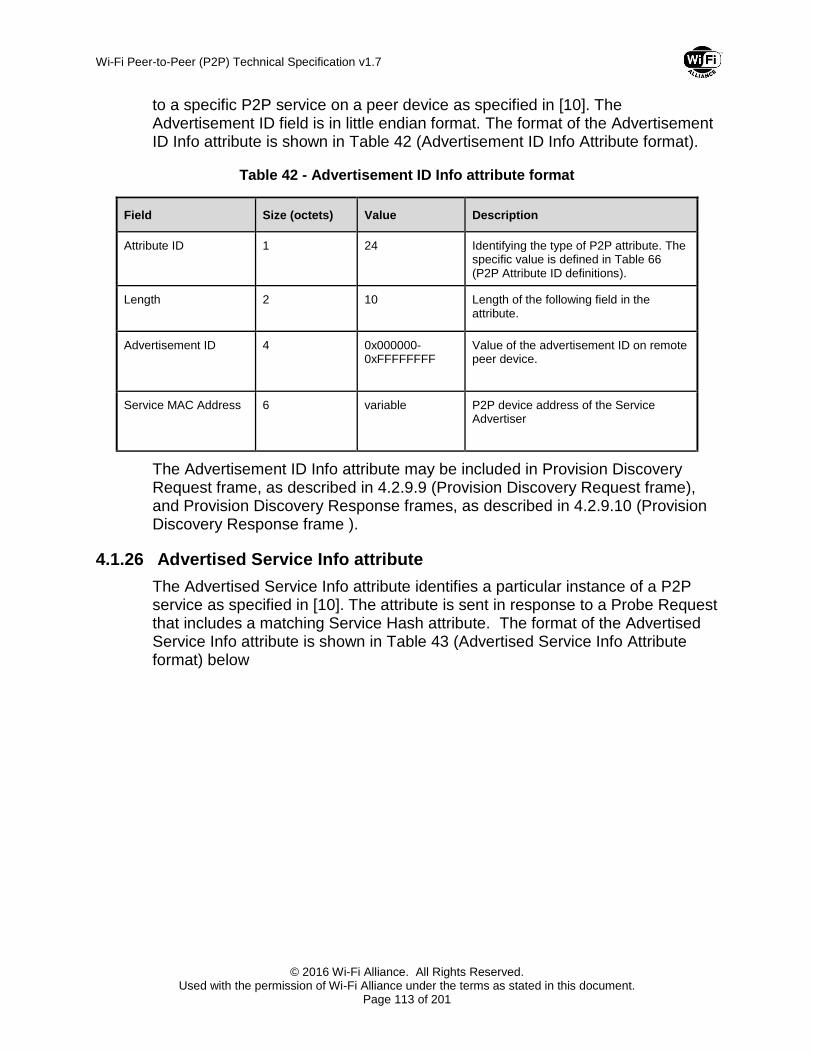
Wi-Fi Peer-to-Peer (P2P) Technical Specification v1.7
© 2016 Wi-Fi Alliance. All Rights Reserved. Used with the permission of Wi-Fi Alliance under the terms as stated in this document.
Page 113 of 201
to a specific P2P service on a peer device as specified in [10]. The Advertisement ID field is in little endian format. The format of the Advertisement ID Info attribute is shown in Table 42 (Advertisement ID Info Attribute format).
Table 42 - Advertisement ID Info attribute format
Field Size (octets) Value Description
Attribute ID 1 24 Identifying the type of P2P attribute. The specific value is defined in Table 66 (P2P Attribute ID definitions).
Length 2 10
Length of the following field in the attribute.
Advertisement ID 4 0x000000-0xFFFFFFFF
Value of the advertisement ID on remote peer device.
Service MAC Address 6 variable P2P device address of the Service Advertiser
The Advertisement ID Info attribute may be included in Provision Discovery Request frame, as described in 4.2.9.9 (Provision Discovery Request frame), and Provision Discovery Response frames, as described in 4.2.9.10 (Provision Discovery Response frame ).
4.1.26 Advertised Service Info attribute
The Advertised Service Info attribute identifies a particular instance of a P2P service as specified in [10]. The attribute is sent in response to a Probe Request that includes a matching Service Hash attribute. The format of the Advertised Service Info attribute is shown in Table 43 (Advertised Service Info Attribute format) below

Wi-Fi Peer-to-Peer (P2P) Technical Specification v1.7
© 2016 Wi-Fi Alliance. All Rights Reserved. Used with the permission of Wi-Fi Alliance under the terms as stated in this document.
Page 114 of 201
Table 43 - Advertised Service Info Attribute format
Field Size (octets) Value Description
Attribute ID 1 25 Identifying the type of P2P attribute. The specific value is defined in Table 66 (P2P Attribute ID definitions).
Length 2 variable
Length of the following fields in the attribute.
Advertised Service Descriptor(s)
Sum of all Advertised Service Descriptor(s)
List of Advertised Service Descriptor(s).
The format of the Advertised Service Descriptor field is shown in Table 44 (Advertised Service Descriptor format) below.
Table 44 - Advertised Service Descriptor format
Field Size (octets) Value Description
Advertisement ID 4 0x00000000-0xFFFFFFFF
Advertisement ID of the local service
Service Config Methods
2 Config Method as defined in [2]
The WSC Methods supported for the corresponding service.
Note — Byte ordering within the Service Config Methods field shall be big-endian.
Service Name Length 1 0x00-0xFF Length of Service Name.
Service Name variable variable UTF-8 string defining the service
The Advertised Service Info attribute may be included in Probe Response frame, as described in Section 4.2.3 (Probe Response frame format).
4.1.27 Session ID Info attribute
The Session ID Info attribute uniquely identifies an ASP-Session. The Session ID Info attribute is used in the Provision Discovery Request frames to request ASP-Session establishment to a specific P2P service on a peer device as specified in [10]. The Session ID field is in little endian. The format of the Session ID Info attribute is shown in Table 45 (Session ID Info Attribute definitions).

Wi-Fi Peer-to-Peer (P2P) Technical Specification v1.7
© 2016 Wi-Fi Alliance. All Rights Reserved. Used with the permission of Wi-Fi Alliance under the terms as stated in this document.
Page 115 of 201
Table 45 - Session ID Info Attribute definitions
Field Size (octets) Value Description
Attribute ID 1 26 Identifying the type of P2P attribute. The specific value is defined in Table 66 (P2P Attribute ID definitions)
Length 2 10
Length of the following field in the attribute.
Session ID 4 0x00000000-0xFFFFFFFF
Value of the session_id
Session MAC Address 6 variable P2P device address of the P2P device which assigned the session_id
The Session ID Info attribute may be included in Provision Discovery Request frame, as described in 4.2.9.9 (Provision Discovery Request frame).
4.1.28 Feature Capability Info attribute
The Feature Capability Info attribute contains feature capabilities of a P2P device as specified in [10]. The format of the Feature Capability Info attribute is shown in Table 46 (Feature Capability Info attribute format).
Table 46 - Feature Capability Info attribute format
Field Size (octets) Value Description
Attribute ID 1 27 Identifying the type of P2P attribute. The specific value is defined in Table 66 (P2P Attribute ID definitions)
Length 2 variable
Length of the following fields in the attribute.
Feature Capability variable variable Refer Section 3.10.5 (ASP-P2P Setup: Feature Capability) of [10] for valid Feature Capability values/bitmask
The Feature Capability attribute may be included in Provision Discovery Request frame, as described in 4.2.9.9 (Provision Discovery Request frame), and Provision Discovery Response frame, as described in 4.2.9.10 (Provision Discovery Response frame).
4.1.29 Persistent Group Info attribute
The Persistent Group Info attribute represents a previously formed P2P Group. The Persistent Group Info attribute is used in the Provision Discovery Request/Response frames to indicate that the peer device has a persistent

Wi-Fi Peer-to-Peer (P2P) Technical Specification v1.7
© 2016 Wi-Fi Alliance. All Rights Reserved. Used with the permission of Wi-Fi Alliance under the terms as stated in this document.
Page 116 of 201
group available to use. The format of the Persistent Group Info attribute is shown in Table 47 (Persistent Group Info Attribute format).
Table 47 - Persistent Group Info Attribute format
Field Size (octets) Value Description
Attribute ID 1 27 Identifying the type of P2P attribute. The specific value is defined in Table 66 (P2P Attribute ID definitions)
Length 2 variable
Total Length of the MAC address plus SSID
P2P device address 6 variable P2P device address of the group owner of the Persistent Group.
SSID 0-32 variable SSID of the Persistent Group
The Persistent Group Info attribute may be included in Provision Discovery Request frame, as described in 4.2.9.9 (Provision Discovery Request frame), and Provision Discovery Response frame, as described in 4.2.9.10 (Provision Discovery Response frame).
4.2 Management Frames
This section defines extensions to 802.11 management frames in support of P2P capabilities.
4.2.1 Beacon frame format
One or more P2P IEs and the WSC IE shall be inserted after other information elements in the Beacon frames transmitted by a P2P Group Owner. P2P attributes for a P2P IE that is included in the Beacon frame are shown in Table 48.
Table 48—P2P attributes in the Beacon frame
Attributes Attribute ID Note
P2P Capability 2 The P2P Capability attribute shall be present in the P2P IE.
P2P Device ID 3 The P2P Device ID attribute shall be present in the P2P IE.

Wi-Fi Peer-to-Peer (P2P) Technical Specification v1.7
© 2016 Wi-Fi Alliance. All Rights Reserved. Used with the permission of Wi-Fi Alliance under the terms as stated in this document.
Page 117 of 201
Attributes Attribute ID Note
Notice of Absence 12 The Notice of Absence attribute shall be present in the P2P IE in the Beacon frames transmitted by a P2P Group Owner when a Notice of Absence schedule is being advertised (see Section 3.3.3.2), or when the CTWindow is non-zero (see Section 3.3.2).
4.2.2 Probe Request frame format
The Probe Request frames can be transmitted by any P2P Device.
One or more P2P IEs and the WSC IE shall be inserted after other information elements in the Probe Request frames transmitted by a P2P Device as shown in Table 49.
Table 49—Probe Request frame format
Order Information
Element Note
WSC IE The WSC IE shall be present in the frames transmitted by a P2P Device.
Last P2P IE The P2P IE shall be present in the frames transmitted by a P2P Device.
Additional attributes shall be inserted in the WSC IE that is included in the Probe Request frame as shown in Table 50.
Table 50—Additional attributes in WSC IE in the Probe Request frame
Attributes Required/ Optional
Note
Device Name Required The Device Name attribute shall be present in WSC IE in the Probe Request frame that is transmitted by a P2P Device.
Requested Device Type
Optional The Requested Device Type attribute may be present in WSC IE in the Probe Request frame that is transmitted by a P2P Device.
P2P attributes for a P2P IE that is included in the Probe Request frame are shown in Table 51.

Wi-Fi Peer-to-Peer (P2P) Technical Specification v1.7
© 2016 Wi-Fi Alliance. All Rights Reserved. Used with the permission of Wi-Fi Alliance under the terms as stated in this document.
Page 118 of 201
Table 51—P2P attributes in the Probe Request frame
Attributes Attribute ID Note
P2P Capability 2 The P2P Capability attribute shall be present in the P2P IE.
P2P Device ID 3 The P2P Device ID attribute may be present in the Probe Request frame when using the discovery protocol to find a P2P Device with a specific Device Address.
Listen Channel 6 The Listen Channel attribute shall be present in the P2P IE indicating the operating class and channel number on which the P2P Device is in the Listen State. If the P2P Device has not selected a Listen Channel, the Listen Channel attribute shall be omitted.
Extended Listen Timing
8 The Extended Listen Timing attribute may be present in the P2P IE to advertise Listen State availability of the P2P Device sending the Probe Request.
P2P Device Info 13 For operation within DMG, the P2P Device Info attribute shall be present in the P2P IE to indicate the P2P Device information.
Operating Channel 17 The Operating Channel attribute shall only be present in the P2P IE if the P2P Device is an operating P2P Group Owner and indicates the operating class and channel number on which the P2P Device is operating as P2P Group Owner.
Service Hash 21 The Service Hash attribute may be present in the P2P IE if P2Ps is supported. The usage of this attribute is defined in the Wi-Fi Peer-to-Peer Services specification [10].
4.2.3 Probe Response frame format
The Probe Response frames can be transmitted by a P2P Device either in its Operating Channel or Listen Channel.
One or more P2P IEs and the WSC IE shall be inserted after other information elements in Probe Response frames transmitted by a P2P Device. P2P attributes for a P2P IE that is included in the Probe Response frame are shown in Table 52.
Table 52—P2P attributes in the Probe Response frame
Attributes Attribute ID Note
P2P Capability 2 The P2P Capability attribute shall be present in the P2P IE.
Extended Listen Timing
8 The Extended Listen Timing attribute may be present in the P2P IE.

Wi-Fi Peer-to-Peer (P2P) Technical Specification v1.7
© 2016 Wi-Fi Alliance. All Rights Reserved. Used with the permission of Wi-Fi Alliance under the terms as stated in this document.
Page 119 of 201
Attributes Attribute ID Note
Notice of Absence 12 The Notice of Absence attribute shall only be present in the P2P IE in the Probe Response frames transmitted by a P2P Group Owner when a Notice of Absence schedule (see Section 3.3.3.2) or non-zero CTWindow (see Section 3.3.2) is being advertised in the Beacon frames (see Section 3.3.3.2).
P2P Device Info 13 The P2P Device Info attribute shall be present in the P2P IE to indicate the P2P Device information.
P2P Group Info 14 The P2P Group Info attribute shall only be present in the P2P IE in the Probe Response frame that is transmitted by a P2P Group Owner. The P2P Group Info attribute shall be omitted if there are zero connected P2P Clients.
Advertised Service Info
25 The Service Instance attribute may be present in the P2P IE if P2Ps is supported. The usage of this attribute is defined in the Wi-Fi Peer-to-Peer Services specification [10].
4.2.4 Association/Reassociation Request frame format
One or more P2P IEs shall be inserted after other information elements in the Association Request or Reassociation Request frame transmitted by a P2P Device.
P2P attributes for a P2P IE that is included in the Association Request or Reassociation Request frame Response frames sent to a P2P Device are shown in Table 53.
Table 53—P2P attributes in the Association/Reassociation Request frame
Attributes Attribute ID Note
P2P Capability 2 The P2P Capability attribute shall be present in the P2P IE.
Extended Listen Timing
8 The Extended Listen Timing attribute may be present in the P2P IE in Association Request or Reassociation Request frames transmitted by a P2P Client.
P2P Device Info 13 The P2P Device Info attribute shall be present in the P2P IE.
P2P attributes for a P2P IE that is included in the Association Request or Reassociation Request frame Response frames sent to a WLAN AP by the WLAN-STA interface of a Managed P2P Device are shown in Table 54.

Wi-Fi Peer-to-Peer (P2P) Technical Specification v1.7
© 2016 Wi-Fi Alliance. All Rights Reserved. Used with the permission of Wi-Fi Alliance under the terms as stated in this document.
Page 120 of 201
Table 54—P2P attributes in the Association/Reassociation Request frame sent to a WLAN AP by a Managed P2P Device
Attributes Attribute ID Note
P2P Capability 2 The P2P Capability attribute shall be present in the P2P IE.
P2P Interface 16 The P2P Interface attribute shall be present in the P2P IE if the Managed P2P Device is a P2P Concurrent Device.
4.2.5 Association/Reassociation Response frame format
One or more P2P IEs shall be inserted after other information elements in the Association Response or Reassociation Response frame transmitted by a P2P Device. P2P attributes for a P2P IE that is included in the Association Response or Reassociation Response frames are shown in Table 55.
Table 55—P2P attributes in the Association/Reassociation Response frame
Attributes Attribute ID Note
Status 0 The Status attribute shall be present in the P2P IE to provide status information when a (Re) association Request frame is denied.
Extended Listen Timing
8 The Extended Listen Timing attribute may be present in the P2P IE in Association Response or Reassociation Response frames transmitted by a P2P Group Owner.
Note — At least one P2P IE is always included in the Association/Reassociation Response frame. If neither P2P attribute is required according to the conditions in Table 55, then a P2P IE containing no P2P attributes is included.
4.2.6 Deauthentication frame format
For operation outside DMG, a P2P IE containing the P2P attributes in Table 56 may be included in a Deauthentication frame transmitted by a WLAN AP that is capable of managing P2P Devices.
Table 56—P2P attributes in the Deauthentication frame
Attributes Attribute ID Note
Minor Reason Code 1 The Minor Reason Code attribute shall be present in the P2P IE.

Wi-Fi Peer-to-Peer (P2P) Technical Specification v1.7
© 2016 Wi-Fi Alliance. All Rights Reserved. Used with the permission of Wi-Fi Alliance under the terms as stated in this document.
Page 121 of 201
4.2.7 Disassociation frame format
A P2P IE containing the P2P attributes in Table 57 may be included in a Disassociation frame transmitted by a WLAN AP that is capable of managing P2P Devices.
Table 57—P2P attributes in the Disassociation frame
Attributes Attribute ID Note
Minor Reason Code
1 The Minor Reason Code attribute shall be present in the P2P IE.
4.2.8 IP Address Allocation in EAPOL-Key Frames (4-Way Handshake)
An IPv4 address may be allocated to a P2P Client in a secure manner by using vendor specific KDEs (Wi-Fi Alliance OUI: 50 6F 9A) in EAPOL-Key frames 2 and 3 during the 4-way EAPOL-Key Handshake.
If a P2P Client supports IP address allocation via EAPOL-Key frames, and the Group Owner to which it is associating advertises support for IP Address Allocation in its Group Capability Bitmap field, the P2P Client may request an IPv4 address allocation from the P2P Group Owner by adding an IP Address Request KDE to EAPOL-Key frame 2. If not advertised by the GO, the P2P Client shall not send the request.
If a P2P Group Owner supports IP address allocation via EAPOL-Key frames it shall set the IP Address Allocation field in its Group Capability Bitmap field to 1 and, on receipt of an IP Address Request KDE in a successful EAPOL-Key frame 2, provide an IP address to the P2P Client through the IP Allocation KDE in EAPOL-Key frame 3.
The structure of the IP address Request KDE (Data Type:4) and IP Allocation KDE (Data Type: 5) are shown in Table 58 and Table 59.
Table 58—IP Address Request KDE in the EAPOL-Key frame 2
The Request IP Address shall be set to 1 to indicate an IP address allocation request to the P2P Group Owner.
A supplicant should not encrypt the IP Address Request KDE in EAPOL-Key msg 2/4.
Request IP Address
Size (octet) 1

Wi-Fi Peer-to-Peer (P2P) Technical Specification v1.7
© 2016 Wi-Fi Alliance. All Rights Reserved. Used with the permission of Wi-Fi Alliance under the terms as stated in this document.
Page 122 of 201
Table 59—IP Allocation KDE in the EAPOL-Key frame 3
Client IP Address Subnet Mask Group Owner IP
Address
Size (octet) 4 4 4
The Client IP Address shall be set to the address allocated by the P2P Group Owner. The allocated IP address shall be valid throughout the duration of the association between the P2P Group Owner and P2P Client.
The Subnet Mask shall be set to provide the value of the subnet that the P2P Group Owner is using.
The Group Owner IP Address shall be set to the address of the P2P Group Owner.
Refer to IEEE802.11-2012 [1] Section 11.6.2 for further details on EAPOL Key frames and Figure 11-30 for the KDE format.
4.2.9 P2P public action frames
4.2.9.1 General format
The Public Action frame format (as defined in IEEE 802.11-2012 [1]) is used to define the P2P public action frames in this specification. The general format of the P2P public action frames is shown in Table 60.
Table 60—General format of P2P public action frame
Field Size
(octets) Value
(Hexadecimal) Description
Category 1 0x04 IEEE 802.11 public action usage.
Action field 1 0x09 IEEE 802.11 vendor specific usage.
OUI 3 50 6F 9A Wi-Fi Alliance specific OUI.
OUI type 1 0x09 (to be assigned)
Identifying the type or version of action frame. Setting to 09 indicates Wi-Fi Alliance P2P v1.0.
OUI Subtype 1 Identifying the type of P2P public action frame. The specific value is defined in Table 61.
Dialog Token 1 Set to a nonzero value to identify the request/response transaction.
Elements variable Including P2P IE or any information elements defined in IEEE 802.11-2012 [1].
Table 61—P2P public action frame type
Type Notes
0 GO Negotiation Request

Wi-Fi Peer-to-Peer (P2P) Technical Specification v1.7
© 2016 Wi-Fi Alliance. All Rights Reserved. Used with the permission of Wi-Fi Alliance under the terms as stated in this document.
Page 123 of 201
Type Notes
1 GO Negotiation Response
2 GO Negotiation Confirmation
3 P2P Invitation Request
4 P2P Invitation Response
5 Device Discoverability Request
6 Device Discoverability Response
7 Provision Discovery Request
8 Provision Discovery Response
9 – 255 Reserved
4.2.9.2 GO Negotiation Request frame
The GO Negotiation Request frame uses the P2P public action frame format and is transmitted by a P2P Device to another P2P Device to initiate a P2P connection.
The Dialog Token field is set to a nonzero value chosen by the P2P Device sending the GO Negotiation Request frame to identify the request/response /confirm transaction.
The Elements field in the GO Negotiation Request frame contains a P2P IE and WSC IE. P2P attributes for a P2P IE that is included in the GO Negotiation Request frame are shown in Table 62.
Table 62—P2P attributes in the GO Negotiation Request frame
Attributes Attribute ID Note
P2P Capability 2 The P2P Capability attribute shall be present in the P2P IE.
Group Owner Intent 4 The Group Owner Intent attribute shall be present in the P2P IE.
Configuration Timeout
5 The Configuration Timeout attribute shall be present in the P2P IE.
Listen Channel 6 The Listen Channel attribute shall be present in the P2P IE.
Extended Listen Timing
8 The Extended Listen Timing attribute may be present in the P2P IE to advertise Listen State availability of the P2P Device sending the GO Negotiation Request,
Intended P2P Interface Address
9 The Intended P2P Interface Address attribute shall be present in the P2P IE.
Channel List 11 The Channel List attribute shall be present in the P2P IE.

Wi-Fi Peer-to-Peer (P2P) Technical Specification v1.7
© 2016 Wi-Fi Alliance. All Rights Reserved. Used with the permission of Wi-Fi Alliance under the terms as stated in this document.
Page 124 of 201
Attributes Attribute ID Note
P2P Device Info 13 The P2P Device Information attribute shall be present in the P2P IE.
Operating Channel 17 The Operating Channel attribute shall be present in the P2P IE.
The WSC IE that is included in the GO Negotiation Request frame contains the Device Password ID and other attributes as shown in Table 63. The value of Device Password ID attribute shall be set to the specific configuration method that the P2P Device is currently using.
Table 63—WSC IE in the GO Negotiation Request frame
Attribute R/O Allowed Values
Version R 0x10 = version1.0, 0x11 = version 1.1, etc.
Device Password ID R The value of Device Password ID attribute shall be set to the specific configuration method that the P2P Device is currently using. See Section 12 (Data Element Definitions) of the WSC Specification [2].
<other…> O Multiple attributes are permitted.
4.2.9.3 GO Negotiation Response frame
The GO Negotiation Response frame uses the P2P public action frame format and is transmitted by a P2P Device in response of a GO Negotiation frame.
The Dialog Token field is set to a nonzero value received in the GO Negotiation Request frame to identify the request/response/confirm transaction.
The Elements field in the GO Negotiation Response frame contains a P2P IE and WSC IE. P2P attributes for a P2P IE that is present in the GO Negotiation Response frame are shown in Table 64.
Table 64—P2P attributes in the GO Negotiation Response frame
Attributes Attribute ID Note
Status 0 The Status attribute shall be present in the P2P IE.
P2P Capability 2 The P2P Capability attribute shall be present in the P2P IE.
Group Owner Intent 4 The Group Owner Intent attribute shall be present in the P2P IE.
Configuration Timeout
5 The Configuration Timeout attribute shall be present in the P2P IE.

Wi-Fi Peer-to-Peer (P2P) Technical Specification v1.7
© 2016 Wi-Fi Alliance. All Rights Reserved. Used with the permission of Wi-Fi Alliance under the terms as stated in this document.
Page 125 of 201
Attributes Attribute ID Note
Operating Channel 17 The Operating Channel attribute may be present in the P2P IE.
Intended P2P Interface Address
9 The Intended P2P Interface Address attribute shall be present in the P2P IE.
Channel List 11 The Channel List attribute shall be present in the P2P IE.
P2P Device Info 13 The P2P Device Information attribute shall be present in the P2P IE.
P2P Group ID 15 The P2P Group ID attribute shall be present if the P2P Device sending the GO Negotiation Response frame will become P2P Group Owner following Group Owner Negotiation.
The WSC IE that is included in the GO Negotiation Response frame contains the Device Password ID and other attributes as shown in Table 65. The value of Device Password ID attribute shall be set to the specific configuration method that the P2P Device is currently using.
Table 65—WSC IE in the GO Negotiation Response frame
Attribute R/O Allowed Values
Version R 0x10 = version1.0, 0x11 = version 1.1, etc.
Device Password ID R The value of Device Password ID attribute shall be set to the specific configuration method that the P2P Device is currently using. See Section 12 (Data Element Definitions) of the WSC Specification [2].
<other…> O Multiple attributes are permitted.
4.2.9.4 GO Negotiation Confirmation frame
The GO Negotiation Confirmation frame uses the P2P public action frame format and is transmitted by a P2P Device transmitting the Group Owner Request frame to confirm the negotiation completeness.
The Dialog Token field is set to a nonzero value received in the GO Negotiation Response frame to identify the request/response/confirm transaction.
The Elements field in the GO Negotiation Confirmation frame contains a P2P IE. P2P attributes for a P2P IE that is included in the GO Negotiation Confirmation frame are shown in Table 66.

Wi-Fi Peer-to-Peer (P2P) Technical Specification v1.7
© 2016 Wi-Fi Alliance. All Rights Reserved. Used with the permission of Wi-Fi Alliance under the terms as stated in this document.
Page 126 of 201
Table 66—P2P attributes in the GO Negotiation Confirmation frame
Attributes Attribute ID Note
Status 0 The Status attribute shall be present in the P2P IE.
P2P Capability 2 The P2P Capability attribute shall be present in the P2P IE.
Operating Channel 17 The Operating Channel attribute shall be present in the P2P IE.
Channel List 11 The Channel List attribute shall be present in the P2P IE.
P2P Group ID 15 The P2P Group ID attribute shall be present if the P2P Device sending the GO Negotiation Confirmation frame will become P2P Group Owner following Group Owner Negotiation.
4.2.9.5 P2P Invitation Request frame
The P2P Invitation Request frame uses the P2P public action frame format.
The Dialog Token field is set to a nonzero value chosen by the P2P Device sending the P2P Initiation Request frame to identify the request/response transaction.
The Elements field in the P2P Invitation Request frame contains a P2P IE and may contain a WSC IE. P2P attributes for a P2P IE that is present in the P2P Invitation Request frame are shown in Table 67.
Table 67—P2P attributes in the P2P Invitation Request frame
Attributes Attribute ID Note
Configuration Timeout
5 The Configuration Timeout attribute shall be present in the P2P IE.
Invitation Flags 18 The Invitation Flags attribute shall be present in the P2P IE.
Operating Channel 17 The Operating Channel attribute shall be present in the P2P IE if the P2P Invitation Request frame is transmitted by the P2P Group Owner. The Operating Channel attribute may be present in the P2P IE if the P2P Invitation Request frame is transmitted by a P2P Client.
P2P Group BSSID 7 The P2P Group BSSID attribute shall be present in the P2P IE if the P2P Invitation Request frame is transmitted by the P2P Group Owner or by a P2P Client if the Invitation Type in the Invitation Flags attribute is 0, indicating a P2P Invitation Request to join an active P2P Group.
Channel List 11 The Channel List attribute shall be present in the P2P IE.
P2P Group ID 15 The P2P Group ID attribute shall be present in the P2P IE.

Wi-Fi Peer-to-Peer (P2P) Technical Specification v1.7
© 2016 Wi-Fi Alliance. All Rights Reserved. Used with the permission of Wi-Fi Alliance under the terms as stated in this document.
Page 127 of 201
Attributes Attribute ID Note
P2P Device Info 13 The P2P Device Info attribute shall be present in the P2P IE.
If an NFC Static Handover occurs between a P2P Device with NFC Tag and a P2P Device which supports NFC Interface, the WSC IE may be included in the P2P Invitation Request frame. In such a case, the WSC IE contains with the Device Password ID and other attributes as shown in Table 67.
The Device Password ID attribute shall be set to a value that identifies an Out-of-Band Device Password read from an NFC Tag.
Table 68—WSC IE in the P2P Invitation Request Frame
Attribute R/O Allowed Values
Version2 (inside Wi-Fi Alliance Vendor Extension)
R Version 2.0 and above (0x20 = version 2.0, 0x21 = version 2.1 etc.)
Device Password ID R The value of Device Password ID attribute shall be set to the value read from an NFC Tag.
<other…> O Multiple attributes are permitted.
4.2.9.6 P2P Invitation Response frame
The P2P Invitation Response frame uses the P2P public action frame format.
The Dialog Token field is set to a nonzero value received in the P2P Invitation Request frame to identify the request/response transaction.
The Elements field in the P2P Invitation Response frame contains a P2P IE. P2P attributes for a P2P IE that is present in the P2P Invitation Response frame are shown in Table 69.
Table 69—P2P attributes in the P2P Invitation Response frame
Attributes Attribute ID Note
Status 0 The Status attribute shall be present in the P2P IE.
Configuration Timeout
5 The Configuration Timeout attribute shall be present in the P2P IE.
Operating Channel 17 The Operating Channel attribute shall be present in the P2P IE if the P2P Invitation Response frame is transmitted by the P2P Group Owner and the Status field is set to “Success”. The Operating Channel attribute may be present in the P2P IE if the P2P Invitation Response frame is transmitted by a P2P Client.

Wi-Fi Peer-to-Peer (P2P) Technical Specification v1.7
© 2016 Wi-Fi Alliance. All Rights Reserved. Used with the permission of Wi-Fi Alliance under the terms as stated in this document.
Page 128 of 201
Attributes Attribute ID Note
P2P Group BSSID 7 The P2P Group BSSID attribute shall be present in the P2P IE if the P2P Invitation Response frame is transmitted by the P2P Group Owner and the Status field is set to “Success”.
Channel List 11 The Channel List attribute shall be present in the P2P IE if the Status field is set to ‘Success’.
4.2.9.7 Device Discoverability Request frame
The Device Discoverability Request frame uses the P2P public action frame format.
The Dialog Token field is set to a nonzero value chosen by the P2P Device sending the Device Discoverability Request frame to identify the request/response transaction.
The Elements field in the Device Discoverability Request frame contains a P2P IE. P2P attributes for a P2P IE that is present in the Device Discoverability Request frame are shown in Table 70.
Table 70—P2P attributes in the Device Discoverability Request frame
Attributes Attribute ID Note
P2P Device ID 3 The P2P Device ID attribute shall be present in the P2P IE.
P2P Group ID 15 The P2P Group ID attribute shall be present in the P2P IE.
4.2.9.8 Device Discoverability Response frame
The Device Discoverability Response frame uses the P2P public action frame format.
The Dialog Token field is set to a nonzero value received in the Device Discoverability Request frame to identify the request/response transaction.
The Elements field in the Device Discoverability Response frame contains a P2P IE. P2P attributes for a P2P IE that is present in the Device Discoverability Response frame are shown in Table 71
Table 71—P2P attributes in the Device Discoverability Response frame
Attributes Attribute ID Note
Status 0 The Status attribute shall be present in the P2P IE.

Wi-Fi Peer-to-Peer (P2P) Technical Specification v1.7
© 2016 Wi-Fi Alliance. All Rights Reserved. Used with the permission of Wi-Fi Alliance under the terms as stated in this document.
Page 129 of 201
4.2.9.9 Provision Discovery Request frame
The Provision Discovery Request frame uses the P2P public action frame format.
The Dialog Token field is set to a nonzero value chosen by the P2P Device sending the Provision Discovery Request frame to identify the request/response transaction.
The Elements field in the Provision Discovery Request frame contains a P2P IE and WSC IE. P2P attributes for a P2P IE that is included in the Provision Discovery Request frame are shown in Table 72 (P2P attributes in the Provision Discovery Request frame).
Table 72—P2P attributes in the Provision Discovery Request frame
Attributes Attribute ID Note
P2P Capability 2 The P2P Capability attribute shall be present in the P2P IE.
P2P Device Info 13 The P2P Device Info attribute shall be present in the P2P IE.

Wi-Fi Peer-to-Peer (P2P) Technical Specification v1.7
© 2016 Wi-Fi Alliance. All Rights Reserved. Used with the permission of Wi-Fi Alliance under the terms as stated in this document.
Page 130 of 201
Attributes Attribute ID Note
P2P Group ID 15 The P2P Group ID attribute shall be present in the P2P IE when joining an operating P2P Group.
Intended P2P Interface Address
9 The Intended P2P Interface Address attribute may be present in the P2P IE if P2Ps [10] is supported.
Status 0 The Status attribute shall be present in the P2P IE if P2Ps [10] is supported and the corresponding Provision Discovery Request is a follow-on Provision Discovery Request.
Operating Channel 17 The Operating Channel attribute may be present in the P2P IE if P2Ps [10] is supported.
Channel List 11 The Channel List attribute may be present in the P2P IE if P2Ps [10] is supported.
Session Information Data Info
22 The Session Information Data Info attribute may be present in the P2P IE if P2Ps [10] is supported.
Connection Capability Info
23 The Connection Capability Info may be present in the P2P IE if P2Ps [10] is supported.
Advertisement_ID Info
24 The Advertisement_ID Info attribute shall be present in the P2P IE if P2Ps [10] is supported.
Configuration Timeout
5 The Configuration Timeout attribute may be present in the P2P IE if P2Ps [10] is supported.
Listen Channel 6 The Listen Channel attribute may be present in the P2P IE if P2Ps [10] is supported.
Session ID Info 26 The Session ID Info attribute shall be present in the P2P IE if P2Ps [10] is supported.
Feature Capability 27 The Feature Capability attribute shall be presented in the P2P IE if P2Ps [10] is supported.
Persistent Group Info
28 The Persistent Group Info attribute may be presented in the P2P IE if P2Ps [10] is supported.
The Config Methods attribute shall be present in the WSC IE that is included in the Provision Discovery Request frame. A single method shall be set in the Config Methods attribute. The method set in the Config Methods attribute shall indicate which of the receiving P2P Device’s configuration methods that the P2P Device intends to use in Provisioning. For example, if the sending P2P Device intends to use a PIN that the receiving P2P Device Displays it shall use the value ‘Display’; if the sending P2P Device intends to use a PIN that the user of the receiving P2P Device enters it shall use the value ‘Keypad’.
4.2.9.10 Provision Discovery Response frame
The Provision Discovery Response frame uses the P2P public action frame format.

Wi-Fi Peer-to-Peer (P2P) Technical Specification v1.7
© 2016 Wi-Fi Alliance. All Rights Reserved. Used with the permission of Wi-Fi Alliance under the terms as stated in this document.
Page 131 of 201
The Dialog Token field is set to a nonzero value received in the Provision Discovery Request frame to identify the request/response transaction.
The Elements field in the Provision Discovery Response frame may contain a P2P IE and shall contain a WSC IE. A P2P IE shall be present if P2Ps [10] is supported. P2P attributes for a P2P IE that is included in the Provision Discovery Response frame are shown in Table 72 (P2P attributes in the Provision Discovery Response frame).
Table 73 - P2P attributes in the Provision Discovery Response frame
Attributes Attribute ID Note
Status 0 The Status attribute shall be present in the P2P IE if P2Ps [10] is supported.
P2P Capability 2 The P2P Capability attribute shall be present in the P2P IE if P2Ps [10] is supported.
P2P Device Info 13 The P2P Device Info attribute shall be present in the P2P IE if P2Ps [10] is supported.
P2P Group ID 15 The P2P Group ID attribute may be present if P2Ps [10] is supported,
Intended P2P Interface Address
9 The Intended P2P Interface Address attribute may be present in the P2P IE if P2Ps [10] is supported.
Operating Channel 17 The Operating Channel attribute may be present in the P2P IE if P2Ps [10] is supported.
Channel List 11 The Channel List attribute may be present in the P2P IE if P2Ps [10] is supported.
Connection Capability Info
23 The Connection Capability Info may be present in the P2P IE if P2Ps [10] is supported.
Advertisement ID Info
24 The Advertisement_ID Info attribute shall be present in the P2P IE if P2Ps [10] is supported.
Configuration Timeout
5 The Configuration Timeout attribute may be present in the P2P IE if P2Ps [10] is supported.
Session ID Info 26 The Session ID Info attribute shall be present in the P2P IE if P2Ps [10] is supported.
Feature Capability 27 The Feature Capability attribute shall be presented in the P2P IE if P2Ps [10] is supported.
Persistent Group Info
28 The Persistent Group Info attribute may be presented in the P2P IE if P2Ps [10] is supported.
Session Information Data Info
22 The Session Information Data Info attribute may be present in the P2P IE if P2Ps [10] is supported.
The Config Methods attribute shall be present in the WSC IE that is included in the Provision Discovery Response frame. The value of the Config Methods attribute shall be set to the same value received in the Provision Discovery

Wi-Fi Peer-to-Peer (P2P) Technical Specification v1.7
© 2016 Wi-Fi Alliance. All Rights Reserved. Used with the permission of Wi-Fi Alliance under the terms as stated in this document.
Page 132 of 201
Request frame to indicate success or shall be null to indicate failure of the request.
4.2.10 P2P action frames
4.2.10.1 General format
The Vendor Specific action frame format (as defined in IEEE 802.11-2012 [1]) is used to define the P2P action frames in this specification. The general format of the P2P action frames is shown in Table 74.
The Notice of Absence, P2P Presence Request, and P2P Presence Response frames shall not be transmitted when operating within DMG.
Table 74—General format of P2P action frame
Field Size
(octets) Value
(Hexadecimal) Description
Category 1 0x7F IEEE 802.11 vendor specific usage (IEEE 802.11-2012 [1] Table 7-24).
OUI 3 50 6F 9A Wi-Fi Alliance specific OUI.
OUI type 1 0x09 (to be assigned)
Identifying the type or version of action frame. Setting to 09 indicates Wi-Fi P2P v1.0.
OUI Subtype 1 Identifying the type of P2P action frame. The specific value is defined in Table 75.
Dialog Token 1 When set to a nonzero value, used to identify the request/response transaction.
Elements variable Including P2P IE or any information elements defined in IEEE 802.11-2012 [1].
Table 75—P2P action frame type
Type Notes
0 Notice of Absence
1 P2P Presence Request
2 P2P Presence Response
3 GO Discoverability Request
4 – 255 Reserved

Wi-Fi Peer-to-Peer (P2P) Technical Specification v1.7
© 2016 Wi-Fi Alliance. All Rights Reserved. Used with the permission of Wi-Fi Alliance under the terms as stated in this document.
Page 133 of 201
4.2.10.2 Notice of Absence frame
The Notice of Absence P2P action frame uses the P2P Specific Action frame format and may be transmitted by a P2P Group Owner to advertise a Notice of Absence schedule.
The Dialog Token field in a Notice of Absence P2P action frame shall be set to 0 on transmission and ignored on reception.
The Elements field in a Notice of Absence action frame shall contain a P2P IE with a single Notice of Absence attribute.
4.2.10.3 P2P Presence Request frame
The P2P Presence Request action frame uses the P2P Action frame format and may be transmitted by a P2P Client to influence P2P Group Owner power management timing.
The Dialog Token field in a Client P2P action frame shall be set to a non-zero value selected by the P2P Client to identify the P2P Presence Request-Response transaction.
The Elements field in a P2P Presence Request action frame shall contain a P2P IE with a single Notice of Absence attribute describing the requested P2P Group Owner presence timing, see Section 3.3.4.4.
4.2.10.4 P2P Presence Response frame
The P2P Presence Response P2P action frame uses the P2P Action frame format and is transmitted by a P2P Group Owner in response to a P2P Presence Request frame.
The Dialog Token field in the P2P Presence Response P2P action frame shall be set to the value received in the corresponding P2P Presence Request frame.
The Elements field in a P2P Presence Response frame shall contain a P2P IE with a Status attribute, followed by one Notice of Absence attribute describing the P2P Group Owner power save timing that the P2P Group Owner will use in response to the P2P Presence Request.
4.2.10.5 GO Discoverability Request frame
The GO Discoverability Request P2P action frame uses the P2P Action frame format and is transmitted by a P2P Group Owner to a P2P Client when a P2P Device has sent the P2P Group Owner a P2P Device Discoverability Request frame.
The Dialog Token field in the GO Discoverability Request P2P action frame shall be NULL.
There is no Elements field in a GO Discoverability Request frame.
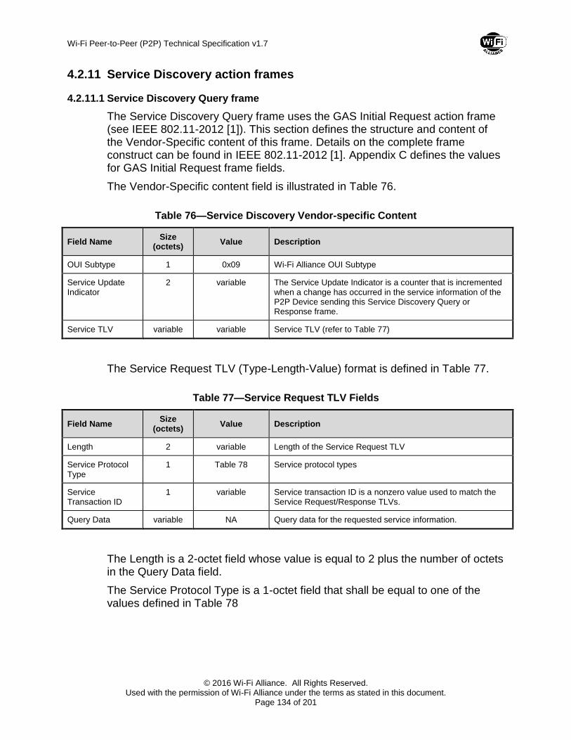
Wi-Fi Peer-to-Peer (P2P) Technical Specification v1.7
© 2016 Wi-Fi Alliance. All Rights Reserved. Used with the permission of Wi-Fi Alliance under the terms as stated in this document.
Page 134 of 201
4.2.11 Service Discovery action frames
4.2.11.1 Service Discovery Query frame
The Service Discovery Query frame uses the GAS Initial Request action frame (see IEEE 802.11-2012 [1]). This section defines the structure and content of the Vendor-Specific content of this frame. Details on the complete frame construct can be found in IEEE 802.11-2012 [1]. Appendix C defines the values for GAS Initial Request frame fields.
The Vendor-Specific content field is illustrated in Table 76.
Table 76—Service Discovery Vendor-specific Content
Field Name Size
(octets) Value Description
OUI Subtype 1 0x09 Wi-Fi Alliance OUI Subtype
Service Update Indicator
2 variable The Service Update Indicator is a counter that is incremented when a change has occurred in the service information of the P2P Device sending this Service Discovery Query or Response frame.
Service TLV variable variable Service TLV (refer to Table 77)
The Service Request TLV (Type-Length-Value) format is defined in Table 77.
Table 77—Service Request TLV Fields
Field Name Size
(octets) Value Description
Length 2 variable Length of the Service Request TLV
Service Protocol Type
1 Table 78 Service protocol types
Service Transaction ID
1 variable Service transaction ID is a nonzero value used to match the Service Request/Response TLVs.
Query Data variable NA Query data for the requested service information.
The Length is a 2-octet field whose value is equal to 2 plus the number of octets in the Query Data field.
The Service Protocol Type is a 1-octet field that shall be equal to one of the values defined in Table 78

Wi-Fi Peer-to-Peer (P2P) Technical Specification v1.7
© 2016 Wi-Fi Alliance. All Rights Reserved. Used with the permission of Wi-Fi Alliance under the terms as stated in this document.
Page 135 of 201
Table 78—Service Protocol Types
Value Meaning
0 All Service Protocol Types
1 Bonjour
2 UPnP
3 WS-Discovery
4 Display
5 WiGig Display Extension over MAC – TX
6 WiGig Display Extension over MAC – RX
7 WiGig Serial Extension over MAC – Host
8 WiGig Serial Extension over MAC – Device
9 WiGig Bus Extension over MAC
10 WiGig SD Extension over MAC
11 Peer-to-Peer services (P2Ps)
12-254 Reserved
255 Vendor Specific
The Service Transaction ID is a 1-octet field set to a nonzero value by the device sending the request. This field is used to identify the Service Request TLV.
The Query Data field value is dependent on the requested Service Protocol Type. The Query Data field shall include the service information type pertaining to the requested service protocol type. If the Service Protocol Type is vendor specific, the value of the Query Data field shall be pre-pended with the vendor’s OUI.
The Bonjour services are registered in the DNS SRV (RFC 2782) Service Types website (http://www.dns-sd.org/ServiceTypes.html).
The UPnP services are registered in the Universal Plug and Play Forum website (http://www.upnp.org).
Web Services Dynamic Discovery (WS-Discovery) is specified in [6].
The WiGig Display Extension, WiGig Bus Extension, and WiGig SD Extension services are defined at Wi-Fi Alliance (www.wi-fi.org). WiGig Serial Extension services are defined at USB Forum (www.usb.org).
4.2.11.2 Service Discovery Response frame
The Service Discovery Response uses the GAS Initial Response action frame. This section defines the structure and content of the Vendor-Specific content of

Wi-Fi Peer-to-Peer (P2P) Technical Specification v1.7
© 2016 Wi-Fi Alliance. All Rights Reserved. Used with the permission of Wi-Fi Alliance under the terms as stated in this document.
Page 136 of 201
this frame. Details on the complete frame construct can be found in IEEE 802.11-2012 [1]. Appendix C defines the values for GAS Initial Response frame fields.
The Vendor-Specific content field is illustrated in Table 76.
The Service Response TLV (Type-Length-Value) format is defined in Table 79.
Table 79—Service Response TLV Fields
Field Name Size
(octets) Value
(Hexadecimal) Description
Length 2 variable Length of the Service Response TLV
Service Protocol Type
1 Table 78 Service protocol types
Service Transaction ID
1 variable Service transaction ID is a nonzero value used to match the Service Request/Response TLVs.
Status Code 1 Table 80 Status code for the requested service information.
Response Data variable NA Response Data is dependent on the requested service information type in the Query Data field of the Service Request.
The Length is a 2-octet field whose value is equal to 3 plus the number of octets in the Response Data field.
The Service Protocol Type is a 1-octet field that shall be equal to one of the values defined in Table 78.
The Service Transaction ID is a 1-octet field set to the Service Transaction ID value in the corresponding Service Request TLV.
The Status Code is a 1-octet field that shall be equal to one of the values defined in Table 80.
Table 80—Service Discovery Status Codes
Value Meaning
0 Success
1 Service Protocol Type not available
2 Requested information not available
3 Bad Request
4–255 Reserved
The value of the Response Data field is dependent on the requested Service Protocol Type and the service information type encoded in the Query Data field.

Wi-Fi Peer-to-Peer (P2P) Technical Specification v1.7
© 2016 Wi-Fi Alliance. All Rights Reserved. Used with the permission of Wi-Fi Alliance under the terms as stated in this document.
Page 137 of 201
The value of the Response Data field shall contain the requested service information type and relevant service data. If the Service Protocol Type is vendor specific, the value of the Response Data field shall be pre-pended with the vendor’s OUI.
4.2.12 FST action frames
4.2.12.1 FST Setup Request and FST Setup Response frames
A P2P Device shall include a P2P IE in each transmitted FST Setup Request and FST Setup Response frames. The P2P IE shall be included after other information elements in the frame.
The P2P attributes for a P2P IE that are included in an FST Setup Request and FST Setup Response frames are shown in Table 81. All P2P attributes included in these frames correspond to the frequency band and channel specified in the Multi-band element contained in the frame carrying the P2P IE. The P2P Group BSSID and P2P Group ID attributes are not included in the P2P IE. However, their corresponding fields are specified as part of the Multi-band element that is contained in the frame carrying the P2P IE.
Table 81—P2P attributes in FST Setup Request and FST Setup Response frames
Attributes Attribute ID Note
P2P Capability 2 The P2P Capability attribute shall be present in the P2P IE.
4.3 DMG Frames
4.3.1 DMG Beacon and Announce frame format
A P2P Device may transmit one or more P2P IEs and the WSC IE within all DMG Beacon frames transmitted in a BTI. In addition, a P2P Device shall transmit one or more P2P IEs and the WSC IE within all Announce frames transmitted in an ATI. In both cases, these IEs shall be included after other information elements in the frame.
The P2P attributes for a P2P IE that are included in a DMG Beacon and Announce frames are shown in Table 82.
Table 82—P2P attributes in the DMG Beacon and Announce frames
Attributes Attribute ID Note
P2P Capability 2 The P2P Capability attribute shall be present in the P2P IE if the P2P IE is included in the frame.
P2P Device ID 3 The P2P Device ID attribute shall be present in the P2P IE if the P2P IE is included in the frame.

Wi-Fi Peer-to-Peer (P2P) Technical Specification v1.7
© 2016 Wi-Fi Alliance. All Rights Reserved. Used with the permission of Wi-Fi Alliance under the terms as stated in this document.
Page 138 of 201
4.3.2 Information request frame format
Information Request frames can be transmitted by any P2P Device according to the rules specified in IEEE 802.11-REVmc [11].
One or more P2P IEs and the WSC IE shall be inserted after other information elements in Information Request frames transmitted by a P2P Device as shown in Table 83.
Table 83—Information Request frame format
Order Information
Element Note
WSC IE The WSC IE shall be present in the frames transmitted by a P2P Device.
Last P2P IE The P2P IE shall be present in the frames transmitted by a P2P Device.
Table 84 lists the additional WSC IE attributes for the Information Request frame.
Table 84—Additional WSC IE attributes for the Information Request frame
Attributes Required/Optional Note
Device Name Required The Device Name attribute shall be present in WSC IE in the Information Request frame that is transmitted by a P2P Device.
Requested Device Type
Optional The Requested Device Type attribute may be present in WSC IE in the Information Request frame that is transmitted by a P2P Device.
Table 85 lists the P2P IE attributes for the Information Request frame.
Table 85—P2P IE attributes for the Information Request frame
Attributes Attribute ID Note
P2P Capability 2 The P2P Capability attribute shall be present in the P2P IE.
P2P Device ID 3 The P2P Device ID attribute may be present in the Information Request frame to find a P2P Device with a specific Device Address.
Listen Channel 6 The Listen Channel attribute shall be present in the P2P IE to indicate the operating class and channel number of the P2P Device when it is in the Listen State. If the P2P Device has not selected a Listen Channel, the Listen Channel attribute shall be omitted.
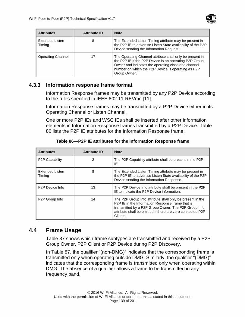
Wi-Fi Peer-to-Peer (P2P) Technical Specification v1.7
© 2016 Wi-Fi Alliance. All Rights Reserved. Used with the permission of Wi-Fi Alliance under the terms as stated in this document.
Page 139 of 201
Attributes Attribute ID Note
Extended Listen Timing
8 The Extended Listen Timing attribute may be present in the P2P IE to advertise Listen State availability of the P2P Device sending the Information Request.
Operating Channel 17 The Operating Channel attribute shall only be present in the P2P IE if the P2P Device is an operating P2P Group Owner and indicates the operating class and channel number on which the P2P Device is operating as P2P Group Owner.
4.3.3 Information response frame format
Information Response frames may be transmitted by any P2P Device according to the rules specified in IEEE 802.11-REVmc [11].
Information Response frames may be transmitted by a P2P Device either in its Operating Channel or Listen Channel.
One or more P2P IEs and WSC IEs shall be inserted after other information elements in Information Response frames transmitted by a P2P Device. Table 86 lists the P2P IE attributes for the Information Response frame.
Table 86—P2P IE attributes for the Information Response frame
Attributes Attribute ID Note
P2P Capability 2 The P2P Capability attribute shall be present in the P2P IE.
Extended Listen Timing
8 The Extended Listen Timing attribute may be present in the P2P IE to advertise Listen State availability of the P2P Device sending the Information Response.
P2P Device Info 13 The P2P Device Info attribute shall be present in the P2P IE to indicate the P2P Device information.
P2P Group Info 14 The P2P Group Info attribute shall only be present in the P2P IE in the Information Response frame that is transmitted by a P2P Group Owner. The P2P Group Info attribute shall be omitted if there are zero connected P2P Clients.
4.4 Frame Usage
Table 87 shows which frame subtypes are transmitted and received by a P2P Group Owner, P2P Client or P2P Device during P2P Discovery.
In Table 87, the qualifier “(non-DMG)” indicates that the corresponding frame is transmitted only when operating outside DMG. Similarly, the qualifier “(DMG)” indicates that the corresponding frame is transmitted only when operating within DMG. The absence of a qualifier allows a frame to be transmitted in any frequency band.

Wi-Fi Peer-to-Peer (P2P) Technical Specification v1.7
© 2016 Wi-Fi Alliance. All Rights Reserved. Used with the permission of Wi-Fi Alliance under the terms as stated in this document.
Page 140 of 201
Table 87—Frame subtype usage
Frame Subtype P2P Device in
the Listen State
P2P Device in the Scan Phase or
Search State
GO Formation Procedure
P2P Client P2P Group
Owner
Beacon (non-DMG) — R — R T
Probe Request (non-DMG)
R T — T R
Probe Request (DMG) R T, R — T T, R
Probe Response (non-DMG)
T R — R T
Probe Response (DMG) T T, R — R T, R
Service Discovery Query
T, R T, R — T, R T, R
Service Discovery Response
T, R T, R — T, R T, R
P2P Invitation Request R T — T, R T, R
P2P Invitation Response
T R — T, R T, R
GO Negotiation Request
R R T, R — —
GO Negotiation Response
— — T, R — —
GO Negotiation Confirmation
— — T, R — —
(Re)Association Request
— — T, R T R
(Re)Association Response
— — T, R R T
Notice of Absence (non-DMG)
— — — R T
P2P Presence Request (non-DMG)
— — — T R
P2P Presence Response (non-DMG)
— — — R T
Device Discoverability Request
— T — — R
Device Discoverability Response
— R — — T
GO Discoverability Request
— — — R T

Wi-Fi Peer-to-Peer (P2P) Technical Specification v1.7
© 2016 Wi-Fi Alliance. All Rights Reserved. Used with the permission of Wi-Fi Alliance under the terms as stated in this document.
Page 141 of 201
Frame Subtype P2P Device in
the Listen State
P2P Device in the Scan Phase or
Search State
GO Formation Procedure
P2P Client P2P Group
Owner
Provision Discovery Request
R T — — R
Provision Discovery Response
T R — — T
Discovery DMG Beacon (DMG)
R T, R — R —
Non-Discovery DMG Beacon (DMG)
R R — R T
Information Request (DMG)
T, R T, R — T, R T, R
Information Response (DMG)
T, R T, R — T, R T, R
Note: T = Transmit; R = Receive; — = not available.

Wi-Fi Peer-to-Peer (P2P) Technical Specification v1.7
© 2016 Wi-Fi Alliance. All Rights Reserved. Used with the permission of Wi-Fi Alliance under the terms as stated in this document.
Page 142 of 201
4.5 NFC NDEF Structure
This section defines the NDEF Record format of the Wi-Fi P2P Carrier Configuration Record, which is referenced by an Alternative Carrier Record embedded within a Handover Request Record in a Handover Request Message, or within a Handover Select Record in a Handover Select Message, as defined in [7]. Further details of NDEF Record format is defined in [8] . It should be noted that, while the descriptions below illustrate Handover Request and Handover Select NDEF Records that only include one Alternative Carrier, Handover Request and Handover Select records may include more than one Alternative Carrier record. Alternative Carrier records may be in any order, thus a device supporting P2P and NFC that receives a NDEF Handover Request Message or a Handover Select Message shall process all records. A device should list Multiple Alternative Carrier records in order of priority in both Handover Request and Handover Select Messages (see [7] for further details).
Note that P2P version negotiation is not practical in all cases for NFC negotiated handover or static handover. Since version negotiation is not possible, future changes to connection handover may require definition of a new MIME type and Alternative Carrier Record.
4.5.1 NFC P2P Handover Request Message
The NFC P2P Handover Request Message shall include the Wi-Fi P2P Carrier Configuration Record as illustrated in Figure 23.

Wi-Fi Peer-to-Peer (P2P) Technical Specification v1.7
© 2016 Wi-Fi Alliance. All Rights Reserved. Used with the permission of Wi-Fi Alliance under the terms as stated in this document.
Page 143 of 201
Wi-Fi P2P Carrier Configuration Record
(mime-type “application/vnd.wfa.p2p”)
(Payload ID “0”)
- Version
- Collision Resolution Record
Handover Request Record
(NFC WKT “Hr”)
Alternative Carrier Record
- Carrier Power State: “active”
- Carrier Data Reference: “0”
UUID-E
RF Bands
WFA Vendor Extension
(includes Version2 sub element)
Manufacturer
Model Name
Model Number
P2P Capability
P2P Device Info
Length of WSC attributes
Length of P2P attributes
Serial Number
Out of Band Group Owner Negotiation
Channel
Out-of-Band Device Password
Public Key Hash
Device Password ID
Channel List (Conditional)
P2P Group Info
(Conditional on Group Owner)
P2P Group ID
(Conditional on Group Owner)
Figure 23—NFC P2P Handover Request Message
The Wi-Fi P2P Carrier Configuration Record contains the device information used for Wi-Fi P2P protocol. WSC attributes defined in Table 88 shall be included in the Wi-Fi P2P Carrier Configuration Record. The overall size occupied by each mandatory WSC attribute shown in Table 88 shall include an

Wi-Fi Peer-to-Peer (P2P) Technical Specification v1.7
© 2016 Wi-Fi Alliance. All Rights Reserved. Used with the permission of Wi-Fi Alliance under the terms as stated in this document.
Page 144 of 201
additional 4 bytes (2 bytes of ID, 2 bytes of length) as defined in [2]. At the head of WSC attributes the length of WSC attributes field shall be included. The size of the Length of WSC attributed field shall be 2 octets. The value held by the Length of WSC attributes field shall be the total length of the following WSC attributes in the Wi-Fi P2P Carrier Configuration Record in octets, using big-endian byte ordering.
Table 88—Mandatory WSC attributes in the Wi-Fi P2P Carrier Configuration Record
ID (Type) Notes
0x1021 Manufacturer
0x1023 Model Name
0x1024 Model Number
0x102C Out-of-Band Device Password
0x103C RF Bands
0x1042 Serial Number
0x1047 UUID-E
0x1049 Wi-Fi Alliance Vendor Extension(includes Version2 sub element)
P2P attributes defined in Table 89 shall be included in the Wi-Fi P2P Carrier Configuration Record. The overall size occupied by each P2P attribute shown in Table 89 shall include an additional 3 bytes (1 byte of ID, 2 bytes of Length). At the head of P2P attributes the Length of P2P attributes shall be included. The size of the Length of P2P attributes field shall be 2 octets. The value held by the Length of P2P attributes field shall be the total length of the following P2P attributes in the Wi-Fi P2P Carrier Configuration Record in octets, big-endian byte ordering.
Table 89—P2P attributes in the Wi-Fi P2P Carrier Configuration Record
ID (Type) Notes Category
2 P2P Capability Mandatory
13 P2P Device Info Mandatory
19 Out-of-Band Group Owner Negotiation Channel
Mandatory
11 Channel List Conditional
14 P2P Group Info Conditional
15 P2P Group ID Conditional

Wi-Fi Peer-to-Peer (P2P) Technical Specification v1.7
© 2016 Wi-Fi Alliance. All Rights Reserved. Used with the permission of Wi-Fi Alliance under the terms as stated in this document.
Page 145 of 201
Devices which cannot provide a preferred operating class or channel number for Out-of-Band Group Owner Negotiation shall also include the Channel List attribute to be used for a full channel search. The unavailability of an operating class or channel number shall be indicated in the Out-of-Band Group Owner Negotiation attribute as defined in 4.1.21.
A Group Owner shall also include the P2P Group Info attribute, if it has at least one P2P client, and the P2P Group ID attribute in the Wi-Fi P2P Carrier Configuration Record.
If the P2P Group Info attribute will not fit into the handover message, for example due to the number of P2P Client Info Descriptors versus the available memory, then the number of included P2P Client Info Descriptors shall be reduced, and the length of the P2P Group Info attribute adjusted accordingly, to fit the available memory size of the NFC Tag. The selection of which P2P Client Info Descriptors to include is an implementation decision. P2P Client Info Descriptors shall not be truncated.
For a device that is currently part of a Group, the channel indicated by the Out-of-Band Group Owner Negotiation Channel attribute shall be the Group’s current operating channel. For a device that is not currently part of a Group, the channel shall be the device’s Listen Channel.
4.5.2 NFC P2P Handover Select Message
The NFC P2P Handover Select Message shall include the Wi-Fi P2P Carrier Configuration Record as illustrated in Figure 24.

Wi-Fi Peer-to-Peer (P2P) Technical Specification v1.7
© 2016 Wi-Fi Alliance. All Rights Reserved. Used with the permission of Wi-Fi Alliance under the terms as stated in this document.
Page 146 of 201
- Version
Handover Select Record
(NFC WKT “Hs”)
Alternative Carrier Record
- Carrier Power State: “active”
- Carrier Data Reference: “0”
Wi-Fi P2P Carrier Configuration Record
(mime-type “application/vnd.wfa.p2p”)
(Payload ID “0”)
UUID-E
RF Bands
WFA Vendor Extension
(includes Version2 sub element)
Manufacturer
Model Name
Model Number
P2P Capability
P2P Device Info
Length of WSC attributes
Length of P2P attributes
Serial Number
Out of Band Group Owner Negotiation
Channel
Out-of-Band Device Password
Public Key Hash
Device Password ID
Device Password
Channel List (Conditional)
P2P Group Info
(Conditional on Group Owner)
P2P Group ID
(Conditional on Group Owner)
Figure 24—NFC P2P Handover Select Message
The Wi-Fi P2P Carrier Configuration Record contains the device information used for Wi-Fi P2P protocol. WSC attributes defined in Table 88 shall be included in the Wi-Fi P2P Carrier Configuration Record.

Wi-Fi Peer-to-Peer (P2P) Technical Specification v1.7
© 2016 Wi-Fi Alliance. All Rights Reserved. Used with the permission of Wi-Fi Alliance under the terms as stated in this document.
Page 147 of 201
When negotiated handover is in use the Device Password shall have zero length. The WSC exchange over 802.11 that follows negotiated handover finishes after provision of WLAN credentials in WSC message M2. When static handover is in use the Device Password shall have non-zero length. The WSC exchange over 802.11 that follows static handover finishes after provision of WLAN credentials in WSC message M8.
The overall size occupied by each mandatory WSC attribute shown in Table 88 shall include an additional 4 bytes (2 bytes of ID, 2 bytes of Length) as defined in [2]. At the head of WSC attributes the Length of WSC attributes field shall be included. The size of the Length of WSC attributes field shall be 2 octets. The value held by the Length of WSC attributes field shall be the total length of the following WSC attributes in the Wi-Fi P2P Carrier Configuration Record in octets, using big-endian byte ordering.
P2P attributes defined in Table 89 shall be included in the Wi-Fi P2P Carrier Configuration Record. The overall size occupied by each P2P attribute shown in Table 89 shall include an additional 3 bytes (1 byte of ID, 2 bytes of Length). At the head of P2P attributes the Length of P2P attributes shall be included. The size of the Length of P2P attributes field shall be 2 octets. The value held by the Length of P2P attributes field shall be the total length of the following P2P attributes in the Wi-Fi P2P Carrier Configuration Record in octets, big-endian byte ordering.
Devices that cannot provide a preferred operating class or channel number for Out-of-Band Group Owner negotiation shall include the Channel List attribute to be used for a full channel search. The unavailability of an operating class or channel number shall be indicated in the Out-of-Band Group Owner negotiation attribute as defined in 4.1.21.
A Group Owner shall include the P2P Group ID attribute in the Wi-Fi P2P Carrier Configuration Record. If a Group Owner has an NFC Interface and has at least one P2P client, then it shall include the P2P Group Info attribute in the Wi-Fi P2P Carrier Configuration Record. If a Group Owner has an NFC Tag, does not have NFC Interface and has at least one P2P client, then it may include the P2P Group Info attribute in the Wi-Fi P2P Carrier Configuration Record.
If the P2P Group Info attribute will not fit into the handover message, for example due to the number of P2P Client Info Descriptors versus the available memory on an NFC Tag, then the number of included P2P Client Info Descriptors shall be reduced, and the length of the P2P Group Info attribute adjusted accordingly, to fit the available memory size. A Group Owner shall not truncate P2P Client Info Descriptors and the selection of which P2P Client Info Descriptors to include is an implementation decision. .
If a device is currently part of a Group, then the device shall set the channel indicated by the Out-of-Band Group Owner Negotiation Channel attribute to the Group’s current operating channel. For a device that is not currently part of a Group the channel shall be the device’s Listen Channel.

Wi-Fi Peer-to-Peer (P2P) Technical Specification v1.7
© 2016 Wi-Fi Alliance. All Rights Reserved. Used with the permission of Wi-Fi Alliance under the terms as stated in this document.
Page 148 of 201
Appendix A P2P State Machine
This Appendix is for informational purposes. It is intended to illustrate the various states and phases defined in the specification and possible transitions between them. The informative diagram of the P2P State Machine is illustrated in Figure A1. It depicts a number of common transitions, and it is neither meant to represent any particular implementation nor meant to be exhaustive of all possible protocol uses. The explanatory text identifies some additional possible transitions, and it is also not meant to be exhaustive.
In this appendix, the following remarks apply when the discovery takes place within DMG:
Message exchanges related to the DMG beamforming procedure are omitted.
Authentication frames are not transmitted.
The term “beacon” or “Beacon” refers to the DMG Beacon frame.

Wi-Fi Peer-to-Peer (P2P) Technical Specification v1.7
© 2016 Wi-Fi Alliance. All Rights Reserved. Used with the permission of Wi-Fi Alliance under the terms as stated in this document.
Page 149 of 201
Figure A1—P2P State Machine
Scan Phase
State: Scan
Actions:
– Scan This action includes scanning all – or a subset of all - supported channels, including possibly passive scanning of certain 5GHz bands. Active scanning is performed by sending Probe Request frames with the P2P IE. Optionally the Probe Request carries information about the type or Device Address of the device that it is asking to respond.
– Exit This action stores the gathered information for use while in Find phase, or directly for use in the Group Owner Negotiation and Provisioning phase or Operational phase

Wi-Fi Peer-to-Peer (P2P) Technical Specification v1.7
© 2016 Wi-Fi Alliance. All Rights Reserved. Used with the permission of Wi-Fi Alliance under the terms as stated in this document.
Page 150 of 201
Internal Behavior:
– Receive Probe Response When a Probe Response message is received, the pertinent information (e.g. Device Name, Device Type, Operating Channel, P2P IE, P2P Device Address – of the Group Owner and all P2P Clients in its Group) is stored for later use and the Scan action is continued.
– Receive Beacon When a Beacon is received, the pertinent information (e.g. Channel, P2P IE) is stored for later use and the Scan action is continued.
Transitions:
– (1) P2P Device found. When another P2P Device is found, the P2P Device may transition to the Group Owner Negotiation and Provisioning phase to negotiate P2P Group ownership.
– (7) P2P Group Owner found. When a P2P Group Owner is found, the P2P Device may transition directly to the Provisioning state – if not yet provisioned – or to the Operational state. Note that this would be similar to the flow of a Legacy Client.
– (14) P2P Group Owner of a previously connected persistent group found. When a P2P Device is found which is the Group Owner of a persistent group, the discovering device may send a P2P Invitation. When accepted, the P2P Device shall transition to the Operational phase.
– (16) Group Owner functionality activated. An active P2P Group Owner may send out beacons, even with no other devices connected.
– (18) Scan Complete. When the scan is completed, the Device may transition to the Find phase.
Find Phase
State: Listen
Actions:
– Pick Random Dwell Time On entering the Listen state, the P2P Device chooses a random dwell between minDiscoverableInterval and maxDiscoverableInterval (the default values for these are 1 and 3 times 100TU respectively).
– Listen on Social Channel The P2P Device listens on the chosen Social Channel for the chosen dwell time.

Wi-Fi Peer-to-Peer (P2P) Technical Specification v1.7
© 2016 Wi-Fi Alliance. All Rights Reserved. Used with the permission of Wi-Fi Alliance under the terms as stated in this document.
Page 151 of 201
Internal Behavior:
– Receive Probe Request with matching parameters When a Probe Request with matching parameters (e.g. P2P IE, P2P Wildcard SSID, Requested Device Type, P2P Device ID) is received, a Probe Response message is sent.
– Receive Beacon When a Beacon is received, the pertinent information (e.g. Channel, P2P IE) is stored for later use and the Listen action is continued.
– Receive Service Discovery Query When a Service Discovery query message is received, and Service Discovery is supported, a Service Discovery Response message is sent.
Transitions:
– (2) Group Owner Negotiation Received. When the P2P Device receives a Group Owner Negotiation message, it shall transition to the Group Formation phase.
– (19) Listen State Completed. When either the chosen random dwell time has passed, or some other (e.g. higher layer or user level) action terminates the Listen State, the P2P Device shall transition to the Search composite state.
– (20) If a P2P Device that is a member of a persistent group is in the listen phase, it may receive a P2P Invitation Request from a previously provisioned P2P Client or Group Owner. In that case it may transition to the Operational phase.
– (Other) A P2P Device may also receive an Invitation Request to join a P2P Group that it has not stored credentials for. In that case it may transition to the WSC Provisioning Enrollee state of the Group Formation procedure.
Composite State: Search
Sub-State: Search
Actions:
– Scan Social Channels
Send Probe Request messages on Social Channels only. Note that the Probe Request message may include either a specific Requested Device Type being searched for, or a P2P Device ID. In the first case, P2P Devices that receive a Probe Request with a Requested Device Type that does not match their own or (in the case that the P2P Device is a Group owner) of that of their Clients should not respond with a Probe Response message. In the second case, P2P Devices that receive a Probe Request with a P2P Device ID containing a Device Address that does not match their own or (in

Wi-Fi Peer-to-Peer (P2P) Technical Specification v1.7
© 2016 Wi-Fi Alliance. All Rights Reserved. Used with the permission of Wi-Fi Alliance under the terms as stated in this document.
Page 152 of 201
the case that the P2P Device is a Group owner) of that of their Clients should not respond with a Probe Response message.
– Exit
This action stores the gathered information from the Search state for later use.
Internal Behavior:
– Receive Probe Response
When a Probe Response message is received, the pertinent information (e.g. Device Name, Device Type, Operating Channel, P2P IE, P2P Device Address – of the Group Owner and all P2P Clients in its Group) is stored for later use and the Search action is continued.
Sub-State: Service Discovery (optional)
Actions:
– Discovery
Send Service Discovery Request messages to previously found P2P Devices that have indicated support for Service Discovery functionality.
– Exit
This action stores the gathered information from the Service Discovery state for later use.
Internal Behavior:
– Receive Service Discovery Response
When a Service Discovery Response message is received, the pertinent information (e.g. Service Name, Service Information) is stored for later use and the Discovery action is continued.
Transitions:
– (3) Persistent P2P Group Owner Found. When a persistent P2P Group Owner is found, for which credentials have been provisioned previously, the P2P Device may send a P2P Invitation. If accepted, the P2P Device may transition to the Operational phase.
– (6) Search State Completed. When all Social Channels have been scanned, and no other transition has been initiated, the P2P Device may transition back to the Listen state of the Find phase.
– (4) P2P Device Found. When another P2P Device is found, the device may move to the Group Formation Procedure.
– (5) P2P Group Owner Found. When a P2P Group Owner is found, the device may transition to the WSC Provisioning Enrollee state – if not yet provisioned – or to the Operational phase. Note that it is also allowed to transition to
Wi-Fi Peer-to-Peer (P2P) Technical Specification v1.7
© 2016 Wi-Fi Alliance. All Rights Reserved. Used with the permission of Wi-Fi Alliance under the terms as stated in this document.
Page 153 of 201
the Group Formation procedure, to negotiate a new (possibly concurrent) P2P Group.
– (Other) When no other P2P Device can be found, the P2P Device may transition back to the Scan phase. Note that an active Group Owner may operate on any channel and has no requirement to listen on a social channel. Therefore it may be that it can only be found during the Scan phase. Note also that as a Group Owner may be in Power Save, it may be hard to find during a short scan of a channel.
Group Formation Procedure
State: Group Owner Negotiation
Actions:
– Group Owner Negotiation The P2P Device either initiates Group Formation, or responds to the Group Owner Negotiation request message received from another P2P Device.
– Exit At the end of the negotiation both parties are in agreement of who is the P2P Group Owner and who is the P2P Client, OR the negotiation fails. Negotiation will fail immediately if provisioning information is not (yet) available on both sides.
Internal Behavior:
– Persistent If during the Group Formation it is established that this is to be a persistent P2P Group, pertinent information (e.g. Device MAC Address, P2P Group ID) is stored for later use
Transitions:
– (9) P2P Device becomes Group Owner. When the P2P Device becomes Group Owner in the Negotiation state, it may transition to the WSC Provisioning Registrar state to establish WSC credentials with the Client.
– (8) P2P Group becomes Client. When the P2P Device becomes a Client in the Negotiation phase, it may transition to the WSC Provisioning Enrollee state to establish WSC credentials with the Group Owner.
– (10) Group Owner Negotiation fails. When Group Owner Negotiation fails for some reason the P2P Device may transition to the Scan or Search Phase, or may seek additional user level input. If the Group Owner Negotiation fails dues to Provisioning Information not being available, either P2P Device may try entering Group Owner Negotiation again at a later time.

Wi-Fi Peer-to-Peer (P2P) Technical Specification v1.7
© 2016 Wi-Fi Alliance. All Rights Reserved. Used with the permission of Wi-Fi Alliance under the terms as stated in this document.
Page 154 of 201
State: WSC Provisioning Enrollee
Actions:
– WSC Provisioning This action includes the whole WSC provisioning process in the role of Enrollee. It is assumed that user level input such as a PIN is already available when Group Owner Negotiation takes place.
– Exit When WSC provisioning is completed, and if this is a persistent P2P Group, the credentials for this group are stored for later use.
Internal Behavior: None
Transitions:
– (13) WSC Provisioning Completed. When WSC Provisioning is completed the P2P Device may transition to the Operational phase.
– (Other) Note that it is possible that WSC provisioning fails, in which case the P2P Device may transition to:
• Scan phase (if the P2P Device is not a Group Owner of a persistent group)
• Operational phase (if it is a Group Owner of an active persistent group)
• Listen state (if it is a Group Owner of one or more persistent groups that are not currently active)
• It may restart Group Formation with a different P2P Device.
Note that these transitions are not explicitly included in the state diagram.
State: WSC Provisioning Registrar
Actions:
– WSC Provisioning This action includes the whole WSC provisioning process in the role of Registrar. It is assumed that user level input such as a PIN is already available when Group Owner Negotiation takes place.
– Exit When WSC provisioning is completed, and if this is a persistent P2P Group, the credentials for this group are stored for later use.
Internal Behavior: None
Transitions:
– (12) WSC Provisioning Completed. When WSC Provisioning is completed the P2P Device may transition to the Operational phase.
– (Other) Note that it is possible that WSC provisioning fails, in which case the P2P Device may transition to:

Wi-Fi Peer-to-Peer (P2P) Technical Specification v1.7
© 2016 Wi-Fi Alliance. All Rights Reserved. Used with the permission of Wi-Fi Alliance under the terms as stated in this document.
Page 155 of 201
• Scan phase (if the P2P Device is not a Group Owner of a persistent group)
• Operational phase (if it is a Group Owner of an active persistent group)
• “Permanent” Listen state (if it is a Group Owner of one or more persistent groups that are not currently active)
• It may restart the Group Formation phase with a different P2P Device.
Note that these transitions are not explicitly included in the state diagram.
Operational Phase
State: P2P Group Owner
Actions:
– Send Beacons The P2P Group Owner shall send Beacon frames.
Internal Behavior:
– Receive Probe Request When a Probe Request message is received, and (if present in a Probe Request that also carries the P2P IE) the Device Type matches the type of the Group Owner or any of the associated P2P Clients, it shall respond with a Probe Response message.
Transitions:
– (17) P2P Device Turned Off When the P2P Device is turned off, it returns to the Off state.
– (15) P2P Group Session Ended When the P2P Group session ends, i.e. there are no other P2P Devices associated with the group, the P2P Device may transition to the Listen state. Note that the P2P Device may remain in the Listen State indefinitely, and it may also alternate listening with periods of sleep. The P2P Device may also transition to the Scan phase, or to the Search phase and of course it may transition to the Off state.
State: P2P Client
Actions: None
Internal Behavior:
– Receive Service Discovery Request When a Service Discovery Request is received, and Service Discovery is supported by the P2P Device, it shall send a P2P Service Discovery Response message.
Transitions:
– (17) P2P Device Turned Off When the P2P Device is turned off, it returns to the Off state.

Wi-Fi Peer-to-Peer (P2P) Technical Specification v1.7
© 2016 Wi-Fi Alliance. All Rights Reserved. Used with the permission of Wi-Fi Alliance under the terms as stated in this document.
Page 156 of 201
– (15) P2P Group Dissolved When the P2P Group session ends, i.e. there are no other P2P Devices associated with the group, the P2P Device may transition to the Scan phase. Alternatively it may transition to the Listen state.

Wi-Fi Peer-to-Peer (P2P) Technical Specification v1.7
© 2016 Wi-Fi Alliance. All Rights Reserved. Used with the permission of Wi-Fi Alliance under the terms as stated in this document.
Page 157 of 201
Appendix B P2P Specific WSC IE Attributes
B.1 Requested Device Type
The Requested Device Type attribute is a P2P specific WSC IE attribute that has been added to the WSC IE in the Probe Request frame (see Section 8.2.4, Table 6 “Attributes in the WSC IE in the Probe Request frame”, of the Wi-Fi Simple Configuration specification [2]). The Requested Device Type attribute is optionally present in the WSC IE in the Probe Request frame.
Attribute Required/Optional Notes
Requested Device Type Optional
The Requested Device Type attribute has been added to Table 28 (Attribute types and sizes) in Section 12 (Data Element Definitions) of the Wi-Fi Simple Configuration specification [2]:
Description ID (Type) Length
Requested Device Type 0x106A 8B
The following text has been added to the list of data elements definitions in Section 12 (Data Element Definitions) of the Wi-Fi Simple Configuration specification [2].
Requested Device Type
This attribute contains the requested device type of a device.
This attribute allows a device to specify the Primary Device Type or the Secondary Device Type of other devices it is interested in. Only a device that receives a Probe Request containing a WSC IE with this attribute and with a Primary Device Type or Secondary Device Type that matches the Requested Device Type will respond with a Probe Response.
Its format and contents is identical to the ‘Primary Device Type’ attribute as defined in the Wi-Fi Simple Configuration specification [2]
Both the Category ID and Sub Category ID can be used as a filter. If only looking for devices with a certain Category ID, the OUI and Sub Category ID fields will have to be set to zero.

Wi-Fi Peer-to-Peer (P2P) Technical Specification v1.7
© 2016 Wi-Fi Alliance. All Rights Reserved. Used with the permission of Wi-Fi Alliance under the terms as stated in this document.
Page 158 of 201
B.2 Primary Device Type
The Primary Device Type attribute contains the primary type of the device. Its format is defined as follows:
0 1 2 3
0 1 2 3 4 5 6 7 8 9 0 1 2 3 4 5 6 7 8 9 0 1 2 3 4 5 6 7 8 9 0 1
+-+-+-+-+-+-+-+-+-+-+-+-+-+-+-+-+-+-+-+-+-+-+-+-+-+-+-+-+-+-+-+-+
| Attribute ID | Length |
+-+-+-+-+-+-+-+-+-+-+-+-+-+-+-+-+-+-+-+-+-+-+-+-+-+-+-+-+-+-+-+-+
| Category ID | OUI (1-2) |
+-+-+-+-+-+-+-+-+-+-+-+-+-+-+-+-+-+-+-+-+-+-+-+-+-+-+-+-+-+-+-+-+
| OUI (3-4) | Sub Category ID |
+-+-+-+-+-+-+-+-+-+-+-+-+-+-+-+-+-+-+-+-+-+-+-+-+-+-+-+-+-+-+-+-+
Vendor-specific sub-categories are designated by setting the OUI to the value associated with that vendor. Note that a four-byte subdivided OUI is used. For the predefined values, the Wi-Fi Alliance OUI of 00 50 F2 04 is used. The predefined values for Category ID and Sub Category ID are provided in Table 41 (Primary Device Type) in Section 12 (Data Element Definitions) of the Wi-Fi Simple Configuration specification [2]. There is no way to indicate a vendor-specific main device category. The OUI applies only to the interpretation of the Sub Category. If a vendor does not use sub categories for their OUI, the three-byte OUI occupies the first three bytes of the OUI field and the fourth byte is set to zero.

Wi-Fi Peer-to-Peer (P2P) Technical Specification v1.7
© 2016 Wi-Fi Alliance. All Rights Reserved. Used with the permission of Wi-Fi Alliance under the terms as stated in this document.
Page 159 of 201
Appendix C GAS Frame Field Value
C.1 GAS Initial Request action frame
The format of the GAS Initial Request frame is defined in IEEE 802.11-2012 [1]. This section defines the values that should be used for this frame. Figure C1 illustrates the GAS Initial Request Action Frame Format and its fields.
GAS Initial Request Action Frame
Category Action Dialog Token Advertisement
Protocol IE Query Request
Length Query Request
4 10 Token ID See below Length See below
1 octet 1 octet 1 octet variable 2 octets variable
Figure C1—GAS Initial Request Action Frame Format
The Category field is set to a value of 4, indicating Public Action Frame.
The Action field is set to a value of 10 for a GAS Initial Request Action Frame.
The Dialog Token is defined in Section 8.4.1.12 of IEEE 802.11-2012 [1] and set by the requesting P2P Device.
Figure C2 illustrates the Advertisement Protocol IE subfield.
Advertisement Protocol Information Element
Element ID Length Advertisement Protocol Tuple
108 Length
Query Response Length Limit
PAME-BI Advertisement Protocol ID
0000000 0 0
1 octet 1 octet 7 bits 1 bit 1 octet
Figure C2—Advertisement Protocol Information Element
The Advertisement Protocol Information Element (IE) is defined in Section 8.4.2.95 in IEEE 802.11-2012 [1]. The Advertisement Protocol element has Element ID 108 (refer to Section 8.4.2 in IEEE 802.11-2012 [1]), a Length field with value 2 and includes exactly one Advertisement Protocol Tuple.
The Advertisement Protocol Tuple is defined in Figure 8-354 in IEEE 802.11-2012 [1]. The Query Response Length Limit shall be set to 0 (bits 0 – 6). The Pre-Associated Message Exchange BSSID Independent (PAME-BI) bit

Wi-Fi Peer-to-Peer (P2P) Technical Specification v1.7
© 2016 Wi-Fi Alliance. All Rights Reserved. Used with the permission of Wi-Fi Alliance under the terms as stated in this document.
Page 160 of 201
shall be set to 0 (bit 7). The Advertisement Protocol ID field shall be equal to 0, Access Network Query Protocol (ANQP).
The Query Request Length field is the total number of octets in the Query Request field.
The Query Request field is a variable container that is illustrated in Figure C3.
ANQP Query Request Field
Info ID Length OI Vendor-Specific Content
56797 Length 50 6F 9A See below
2 octet 2 octets 3 octets variable
Figure C3—ANQP Query Request Field
The Info ID field is set to 56797, which is the value corresponding to the Access Network Query Protocol (ANQP) vendor-specific list.
The Length is a 2-octet field whose value is equal to 3 plus the number of octets in the Vendor-Specific content field.
The OI field shall be equal to 0x50 6F 9A (Wi-Fi Alliance OUI).
Figure C4 illustrates the Vendor-specific content of the ANQP Query Request Frame.
ANQP Query Request Vendor-specific Content
OUI Subtype
Service Update Indicator
ANQP Query Request Vendor-Specific Content TLV
Length Service Protocol
Type Service
Transaction ID Query Data
9 See below Length Table 78 Transaction ID See below
1 octet 2 octets 2 octets 1 octet 1 octet variable
Figure C4—ANQP Query Request Frame Vendor-specific Content
The OUI Subtype is a 1-octet field and is set to 9.
The Service Update Indicator is a counter that is incremented when a change has occurred in the service information of the P2P Device sending this Query Request frame. See Section 3.1.3.1.
The Length is a 2-octet field whose value is equal to 2 plus the number of octets in the Query Data field.
The Service Protocol Type is a 1-octet field set to the corresponding value in Table 78.

Wi-Fi Peer-to-Peer (P2P) Technical Specification v1.7
© 2016 Wi-Fi Alliance. All Rights Reserved. Used with the permission of Wi-Fi Alliance under the terms as stated in this document.
Page 161 of 201
The Service Transaction ID is a 1-octet field.
The Query Data is a variable container based on the requested Service Protocol Type.
The Length, Service Protocol Type, Service Transaction ID and Query Data fields form a TLV structure. There may one or more such TLV structures in the Vendor-specific Content field of the ANQP Query Request frame.
C.2 GAS Initial Response Action Frame
The format of the GAS Initial Response frame is defined in IEEE 802.11-2012 [1]. This section defines the values that should be used for this frame. Figure C5 illustrates the GAS Initial Response Action Frame Format and its fields.
GAS Initial Response Action Frame
Category Action Dialog Token
Status Code
GAS Comeback
Delay
Advertisement Protocol IE
Query Response
Length
Query Response
4 11 Token
ID Table 7-
23 See below See below Length See below
1 octet 1 octet 1 octet 2 octets 2 octets variable 2 octets variable
Figure C5—GAS Initial Response Action Frame Format
The Category field is set to a value of 4 indicating Public Action Frame.
The Action field is set to a value of 11 for a GAS Initial Response Action Frame.
The Dialog Token is copied from the corresponding GAS Initial Request Action frame.
The Status Code values are defined in Table 8-37 of IEEE 802.11-2012 [1].
The GAS Comeback Delay field specifies the delay time value in TU. If the Query Response fits in a single GAS Initial Response frame, the GAS Comeback Delay field shall be set to zero. If the Query Response does not fit in a single GAS Initial Response frame, the GAS Comeback Delay field shall be set to one and the Query Response Length field shall be set to zero, indicating that GAS fragmentation will be used (refer to Section C.3 for information on GAS fragmentation).
Figure C6 illustrates the Advertisement Protocol IE subfield.

Wi-Fi Peer-to-Peer (P2P) Technical Specification v1.7
© 2016 Wi-Fi Alliance. All Rights Reserved. Used with the permission of Wi-Fi Alliance under the terms as stated in this document.
Page 162 of 201
Advertisement Protocol Information Element
Element ID Length Advertisement Protocol Tuple
108 Length
Query Response Length Limit
PAME-BI Advertisement Protocol ID
1111111 0 0
1 octet 1 octet 7 bits 1 bit 1 octet
Figure C6—Advertisement Protocol Information Element
The Advertisement Protocol Information Element (IE) is defined in Section 8.4.2.95 in IEEE 802.11-2012 [1]. The Advertisement Protocol element includes exactly one Advertisement Protocol ID where the Element ID field is set to 108 (refer to Section 8.4.2 in IEEE 802.11-2012 [1]). The Length is a one-octet field whose value is equal to 2.
The Advertisement Protocol Tuple is defined in Figure 8-354 in IEEE 802.11-2012 [1]. The Query Response Length Limit shall be set to 127 (bits 0 – 6). The Pre-Associated Message Exchange BSSID Independent (PAME-BI) bit shall be set to 0 (bit 7). The Advertisement Protocol ID field shall be equal to 0, Access Network Query Protocol (ANQP).
The Query Response Length field is the total number of octets in the Query Response field.
The Query Response field is a variable container as defined in Figure C7.
ANQP Query Response Field
Info ID Length OI Vendor-Specific Content
56797 variable 50 6F 9A See below
2 octets 2 octets 3 octets variable
Figure C7—ANQP Query Response Field Format
The Info ID field is set to 56797, which is the value corresponding to the Access Network Query Protocol (ANQP) vendor-specific list.
The Length is a 2-octet field whose value is equal to 3 plus the number of octets in the Vendor-Specific content field.
The Status Code values are defined in Table 8-37 of IEEE 802.11-2012 [1].
The OI field shall be equal to 0x50 6F 9A (Wi-Fi Alliance OUI).
Figure C8 illustrates the Vendor-specific content field of the ANQP Query Response Frame.

Wi-Fi Peer-to-Peer (P2P) Technical Specification v1.7
© 2016 Wi-Fi Alliance. All Rights Reserved. Used with the permission of Wi-Fi Alliance under the terms as stated in this document.
Page 163 of 201
ANQP Query Response Vendor-specific Content Field
OUI Subtype
Service Update
Indicator
ANQP Query Response Vendor-Specific Content TLV
Length Service Protocol
Type Service
Transaction ID Status Code
Response Data
9 See
below Length Table 78 Transaction ID Table 80 See below
1 octet 2 octets 2 octets 1 octet 1 octet 1 octet variable
Figure C8—ANQP Query Response Frame Vendor-specific Content Field
The OUI Subtype is a 1-octet field and is set to 9.
The Service Update Indicator is a counter that is incremented when a change has occurred in the service information of the P2P Device sending this Query Response frame. See Section 3.1.3.2.
The Length is a 2-octet field whose value is equal to 3 plus the number of octets in the Response Data field.
The Service Protocol Type is a 1-octet field set to the corresponding value in Table 78.
The Service Transaction ID is a 1-octet field set to the corresponding Service Transaction ID in the Service TLV.
The Status Code is a 1-octet field set to the corresponding value in Table 80.
The Response Data is a variable container based on the requested Service Protocol Type.
The Length, Service Protocol Type, Service Transaction ID, Status Code and Response Data fields form a TLV structure. There may one or more such TLV structures in the Vendor-specific Content field of the ANQP Query Response frame.
C.3 GAS Fragmentation
If the GAS Query Response is too large to fit in a single MMPDU, the GAS Fragmentation procedure shall be used. The GAS Fragmentation procedure uses the GAS Comeback Request and GAS Comeback Response frame exchange as defined in IEEE 802.11-2012 [1]. This section defines the GAS Comeback Request and Response frames.
The format of the GAS Comeback Request frame is defined in IEEE 802.11-2012 [1]. This section defines the values that should be used for this frame. Figure C9 illustrates the GAS Comeback Request and its fields.

Wi-Fi Peer-to-Peer (P2P) Technical Specification v1.7
© 2016 Wi-Fi Alliance. All Rights Reserved. Used with the permission of Wi-Fi Alliance under the terms as stated in this document.
Page 164 of 201
GAS Comeback Request Frame
Category Action Dialog Token
4 12 Token ID
1 octet 1 octet 1 octet
Figure C9—GAS Comeback Request Frame Format
The Category field is set to a value of 4, indicating Public Action Frame.
The Action field is set to a value of 12 for a GAS Comeback Request.
The Dialog Token is obtained from the corresponding GAS Initial Request Frame.
The format of the GAS Comeback Response frame is defined in IEEE 802.11-2012 [1]. This section defines the values that should be used for this frame. Figure C10 illustrates the GAS Comeback Response Frame Format and its fields.
GAS Comeback Response Frame
Category Action Dialog Token
Status Code
GAS Query Response
Fragment ID
GAS Comeback
Delay
Advertisement Protocol IE
Query Response
Length
Query Response
4 13 Token
ID Table 7-23
See below See below See below Length See below
1 octet 1 octet 1 octet 2 octets
1 octet 2 octets variable 2 octets variable
Figure C10—GAS Comeback Response Frame Format
The Category field is set to a value of 4 indicating Public Action Frame.
The Action field is set to a value of 13 for a GAS Comeback Response Frame.
The Dialog Token is copied from the corresponding GAS Initial Request Action frame.
The Status Code values are defined in Table 8-37 of IEEE 802.11-2012 [1].
The GAS Query Response Fragment ID is used by a responding P2P Device to indicate when GAS fragmentation is being used. A P2P Device responding to a GAS request uses this field to inform the requesting P2P Device/Client of the GAS fragment number of the transmitted frames as well as identifying the last GAS fragment of the Query Response. The first 7 bits (B0-B6) represent the GAS Query Response Fragment ID and the last bit (B7) represents the More GAS Fragments bit. The GAS Query Response Fragment ID is set to 0 for the initial fragment and increments by 1 for each subsequent Comeback Response
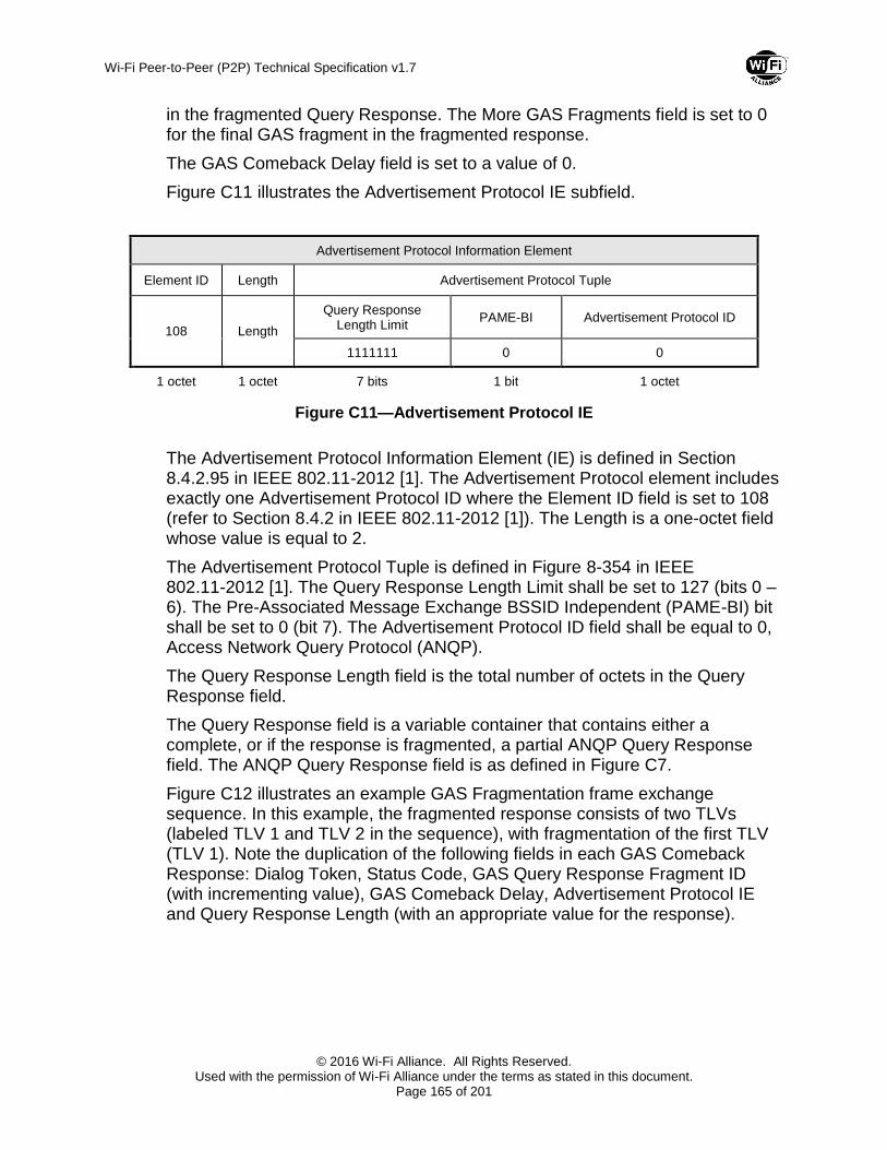
Wi-Fi Peer-to-Peer (P2P) Technical Specification v1.7
© 2016 Wi-Fi Alliance. All Rights Reserved. Used with the permission of Wi-Fi Alliance under the terms as stated in this document.
Page 165 of 201
in the fragmented Query Response. The More GAS Fragments field is set to 0 for the final GAS fragment in the fragmented response.
The GAS Comeback Delay field is set to a value of 0.
Figure C11 illustrates the Advertisement Protocol IE subfield.
Advertisement Protocol Information Element
Element ID Length Advertisement Protocol Tuple
108 Length
Query Response Length Limit
PAME-BI Advertisement Protocol ID
1111111 0 0
1 octet 1 octet 7 bits 1 bit 1 octet
Figure C11—Advertisement Protocol IE
The Advertisement Protocol Information Element (IE) is defined in Section 8.4.2.95 in IEEE 802.11-2012 [1]. The Advertisement Protocol element includes exactly one Advertisement Protocol ID where the Element ID field is set to 108 (refer to Section 8.4.2 in IEEE 802.11-2012 [1]). The Length is a one-octet field whose value is equal to 2.
The Advertisement Protocol Tuple is defined in Figure 8-354 in IEEE 802.11-2012 [1]. The Query Response Length Limit shall be set to 127 (bits 0 – 6). The Pre-Associated Message Exchange BSSID Independent (PAME-BI) bit shall be set to 0 (bit 7). The Advertisement Protocol ID field shall be equal to 0, Access Network Query Protocol (ANQP).
The Query Response Length field is the total number of octets in the Query Response field.
The Query Response field is a variable container that contains either a complete, or if the response is fragmented, a partial ANQP Query Response field. The ANQP Query Response field is as defined in Figure C7.
Figure C12 illustrates an example GAS Fragmentation frame exchange sequence. In this example, the fragmented response consists of two TLVs (labeled TLV 1 and TLV 2 in the sequence), with fragmentation of the first TLV (TLV 1). Note the duplication of the following fields in each GAS Comeback Response: Dialog Token, Status Code, GAS Query Response Fragment ID (with incrementing value), GAS Comeback Delay, Advertisement Protocol IE and Query Response Length (with an appropriate value for the response).

Wi-Fi Peer-to-Peer (P2P) Technical Specification v1.7
© 2016 Wi-Fi Alliance. All Rights Reserved. Used with the permission of Wi-Fi Alliance under the terms as stated in this document.
Page 166 of 201
Status
Code
GAS Initial Response Action Frame
Advertisement
Protocol IE
Category ActionDialog
Token
Advertisement
Protocol IE
Query
Request
Length Info ID Length OI OUI
Subtype
Service
Update
IndicatorLength
Service
Protocol
Type
Service
Transaction ID
Query
DataLength
Service
Protocol
Type
Service
Transaction ID
Query
Data
ANQP Query Request Vendor Specific Content TLV
ANQP Query Request Vendor Specific Content
GAS Initial Request Action Frame
Category ActionDialog
Token
Status
Code
GAS
Comeback
Delay
4 10Token
“A”
Fixed Value
(see Figure C2)Length Length
ANQP Query Request Field
56797 50 6F 9A 9 SUI-Dev1 Length Length0 TID Variable 0 TID + 1 Variable
4 11Token
“A”
Table
7-231
Fixed Value
(see Figure C6)
Query
Response
Length
0
GAS Comeback Request
Action Frame
Category ActionDialog
Token
4 12Token
“A”
Category ActionDialog
Token
Advertisement
Protocol IE
Query
Response
Length
Info ID Length OI OUI
Subtype
Service
Update
Indicator Length
Service
Protocol
Type
Service
Transaction ID
Query
Data
ANQP Query Response Vendor Specific Content
4 13Token
“A”
Fixed Value
(see Figure C6)1415 2810
ANQP Query Response Field
56797 50 6F 9A 9 SUI-Dev2 2000 0 TID 01400
Octets
TLV 1 (Fragment)Status
Code
GAS Query
Response
Fragment
ID
More GAS
Fragments
GAS
Comeback
Delay
GAS Comeback Response Action Frame
0 000000 1 0
GAS Comeback Request
Action Frame
Category ActionDialog
Token
4 12Token
“A”
Status
Code
Category ActionDialog
Token
Advertisement
Protocol IE
Query
Response
Length Service
Protocol
Type
Service
Transaction ID
Query
Data
4 13Token
“A”
Fixed Value
(see Figure C6)1399 0 TID + 1 0
797
Octets
Status
Code
GAS Query
Response
Fragment
ID
More GAS
Fragments
GAS
Comeback
Delay
GAS Comeback Response Action Frame
0 000001 0 0
P2P Device 1 P2P Device 2
GAS Initial Request
GAS Initial Response
GAS Comeback Request
GAS Comeback Response
GAS Comeback Request
GAS Comeback Response
P2P Device 1 P2P Device 1
Query
Data
597
octets
TLV 1
cont.
Length
800
TLV 2
ANQP Query Response Vendor Specific Content (Continued)
ANQP Query Response Field
Figure C12—Example GAS Fragmentation Frame Exchange Sequence

Wi-Fi Peer-to-Peer (P2P) Technical Specification v1.7
© 2016 Wi-Fi Alliance. All Rights Reserved. Used with the permission of Wi-Fi Alliance under the terms as stated in this document.
Page 167 of 201
Appendix D P2P Discovery Diagrams
This Appendix is for informational purposes. It contains a number of message sequence diagrams that are intended to illustrate possible uses of the P2P Discovery protocol in various example scenarios. No attempt made to cover all possible scenarios or protocol uses and for clarity, the diagrams omit many parameters from the exchanged messages.
The diagrams for scenarios 1a and 1b illustrate the discovery sequence when operating both outside and within DMG.
In all other discovery diagrams described herewith, the following remarks apply when the discovery takes place within DMG:
Message exchanges related to the DMG beamforming procedure are omitted.
Authentication frames are not transmitted.
The term “beacon” or “Beacon” refers to the DMG Beacon frame.

Wi-Fi Peer-to-Peer (P2P) Technical Specification v1.7
© 2016 Wi-Fi Alliance. All Rights Reserved. Used with the permission of Wi-Fi Alliance under the terms as stated in this document.
Page 168 of 201
form
ation
form
ation
probe request (P2P IE, )
probe request
Scenario 1a within DMG: Two P2P Devices discovering each other; group formation occurs on Listen Channel of P2P Device 1
P2P Device 1
P2P Device 2
P2P Device 1 P2P Device 2
scan
scanprobe requestprobe requestprobe request
listen
listen
scan
Start Discovery
Note 1
Notes:1) Active, or passive scan.2) Devices select Listen Channels.3) This Probe Response is optional; P2P Device 1 may just send
the GO Negotiation Request.4) P2P Device 1 retries after initial GO Negotiation Request fails.5) P2P Device 2 determines it will be GO, starts a P2P Group
session on the Operating Channel and acts as WSC Registrar to issue Credentials to Client (WSC Enrollee). The Group Formation bit is set to 1 until Provisioning succeeds.
6) Startup may be delayed according to Configuration Timeout information exchanged during GO negotiation.
7) Diagram does not show all message parameters.
Note 2
search
scan
probe requestprobe request
Start Discovery
ch 2
100
TU
100
TU
ch 2
listen
100
TU
ch 2
search
probe request
ch 2
listen
Note 2
10
0T
Uprobe response
service discovery exchange (optional)
Service
Discovery (Opt)
ch 2
formation
Note 3
GO negotiation response (success, intent = 10, config timeout, )
GO negotiation confirm
ch 2
Note 6
GO negotiation request (intent = 3, config timeout )
client
ope
rating c
ha
nnelWSC exchange
association request
associa tion response
4-way handshake
DMG beacon
opera
tion
ope
rating c
ha
nnel
DMG beacon (group formation = 1)
associa tion request
association response
DMG beacon (group formation = 0)
Formation CompleteFormation Complete
opera
tion
formation
ch 2
GO
ch 2
Formation Request
Notes 5, 6
Start Formation
Device Found
Service Discovery (Opt)
find
find
find
ch 2
100
TU
search
10
0T
U
DMG Beamforming (optional)
GO negotiation request (intent = 3 )
GO negotiation response (fail: information unavailable)
ch 2
searchlisten
ch
2 probe request (P2P IE, )
probe response
Note 4
100
TU
100
TU
100
TU
Device Found
Formation Rsp

Wi-Fi Peer-to-Peer (P2P) Technical Specification v1.7
© 2016 Wi-Fi Alliance. All Rights Reserved. Used with the permission of Wi-Fi Alliance under the terms as stated in this document.
Page 169 of 201
form
ation
form
ation
probe request (P2P IE, )
probe request
Scenario 1a within DMG: Two P2P Devices discovering each other; group formation occurs on Listen Channel of P2P Device 1
P2P Device 1
P2P Device 2
P2P Device 1 P2P Device 2
scan
scanprobe requestprobe requestprobe request
listen
listen
scan
Start Discovery
Note 1
Notes:1) Active, or passive scan.2) Devices select Listen Channels.3) This Probe Response is optional; P2P Device 1 may just send
the GO Negotiation Request.4) P2P Device 1 retries after initial GO Negotiation Request fails.5) P2P Device 2 determines it will be GO, starts a P2P Group
session on the Operating Channel and acts as WSC Registrar to issue Credentials to Client (WSC Enrollee). The Group Formation bit is set to 1 until Provisioning succeeds.
6) Startup may be delayed according to Configuration Timeout information exchanged during GO negotiation.
7) Diagram does not show all message parameters.
Note 2
search
scan
probe requestprobe request
Start Discovery
ch 2
100
TU
100
TU
ch 2
listen
100
TU
ch 2
search
probe request
ch 2
listen
Note 2
10
0T
U
probe response
service discovery exchange (optional)
Service
Discovery (Opt)
ch 2
formation
Note 3
GO negotiation response (success, intent = 10, config timeout, )
GO negotiation confirm
ch 2
Note 6
GO negotiation request (intent = 3, config timeout )
client
ope
rating c
ha
nnelWSC exchange
association request
associa tion response
4-way handshake
DMG beacon
opera
tion
ope
rating c
ha
nnel
DMG beacon (group formation = 1)
associa tion request
association response
DMG beacon (group formation = 0)
Formation CompleteFormation Complete
opera
tion
formation
ch 2
GO
ch 2
Formation Request
Notes 5, 6
Start Formation
Device Found
Service Discovery (Opt)
find
find
find
ch 2
100
TU
search
10
0T
U
DMG Beamforming (optional)
GO negotiation request (intent = 3 )
GO negotiation response (fail: information unavailable)
ch 2
searchlisten
ch
2 probe request (P2P IE, )
probe response
Note 4
100
TU
100
TU
100
TU
Device Found
Formation Rsp

Wi-Fi Peer-to-Peer (P2P) Technical Specification v1.7
© 2016 Wi-Fi Alliance. All Rights Reserved. Used with the permission of Wi-Fi Alliance under the terms as stated in this document.
Page 170 of 201

Wi-Fi Peer-to-Peer (P2P) Technical Specification v1.7
© 2016 Wi-Fi Alliance. All Rights Reserved. Used with the permission of Wi-Fi Alliance under the terms as stated in this document.
Page 171 of 201
form
ation
form
ation
probe request
probe request (P2P IE, )
Scenario 1b within DMG: Two P2P Devices discovering each other; group formation occurs on Listen Channel of P2P Device 2
P2P Device 1
P2P Device 2
P2P Device 1 P2P Device 2
scan
scanprobe requestprobe requestprobe request
listen
listenscan
Start Discovery
Note 1Notes:1) Active, or passive scan.2) Devices select Listen Channels.3) P2P Device 1 enters Listen state as part of FIND phase prior to
sending Provision Discover Request on the Channel upon which P2P Device 2 was discovered.
4) Optional Provision Discovery Request-Response message exchange precedes GO Negotiation Request in this scenario.
5) P2P Device 2 determines it will be GO, starts a P2P Group session on the Operating Channel and acts as WSC Registrar to issue Credentials to Client (WSC Enrollee). The Group Formation bit is set to 1 until Provisioning succeeds.
6) Startup may be delayed according to Configuration Timeout information exchanged during GO negotiation.
7) Diagram does not show all message parameters.
Note 2
search
scan
probe requestprobe request
Start Discovery
ch
2
100
TU
100
TU
ch
2
listen
100
TU
100
TU
ch
2
search
probe request
ch
2listen
Note 2
100
TU
probe response
service discovery exchange (optional)
Service
Discovery (Opt)
Note 3
ch
2
10
0T
U100
TU
provision discover request (optional)
provision discover response (optional)
formation
Note 4
GO negotiation response (success, intent = 10, config timeout, )
GO negotiation confirm
ch
2
Note 6
GO negotiation request (intent = 3 config timeout )
client
op
era
tin
g c
ha
nn
el
WSC exchange
association request
association response
4-way handshake
DMG beacon
opera
tion
op
era
tin
g c
ha
nn
el
DMG beacon (group formation = 1)
association request
association response
DMG beacon (group formation = 0)
Formation CompleteFormation Complete
opera
tion
formation
ch
2
GO
ch
2
Formation Indication
Provision Discovery
Notes 5, 6
Start Formation
Device Found
Service Discovery (Opt)
Provision Discover
Req (Opt)
Provision Discover
Resp (Opt)
fin
dfin
d
fin
dfin
d
DMG Beamforming (optional)

Wi-Fi Peer-to-Peer (P2P) Technical Specification v1.7
© 2016 Wi-Fi Alliance. All Rights Reserved. Used with the permission of Wi-Fi Alliance under the terms as stated in this document.
Page 172 of 201

Wi-Fi Peer-to-Peer (P2P) Technical Specification v1.7
© 2016 Wi-Fi Alliance. All Rights Reserved. Used with the permission of Wi-Fi Alliance under the terms as stated in this document.
Page 173 of 201

Wi-Fi Peer-to-Peer (P2P) Technical Specification v1.7
© 2016 Wi-Fi Alliance. All Rights Reserved. Used with the permission of Wi-Fi Alliance under the terms as stated in this document.
Page 174 of 201

Wi-Fi Peer-to-Peer (P2P) Technical Specification v1.7
© 2016 Wi-Fi Alliance. All Rights Reserved. Used with the permission of Wi-Fi Alliance under the terms as stated in this document.
Page 175 of 201

Wi-Fi Peer-to-Peer (P2P) Technical Specification v1.7
© 2016 Wi-Fi Alliance. All Rights Reserved. Used with the permission of Wi-Fi Alliance under the terms as stated in this document.
Page 176 of 201

Wi-Fi Peer-to-Peer (P2P) Technical Specification v1.7
© 2016 Wi-Fi Alliance. All Rights Reserved. Used with the permission of Wi-Fi Alliance under the terms as stated in this document.
Page 177 of 201
Ou
t o
f B
an
d
Ou
t o
f B
an
d
ch
1GO negotiation response (success, intent = 10, config timeout, ...)
GO negotiation request (intent = 3, config timeout...)
ch
1
form
atio
n
op
era
tio
n
op
era
tio
n
P2P Device 1 P2P Device 2
formation
form
atio
n
WPS exchange (NFC Device Password)
authentication (1)
authentication (2)
association request
association response
GO negotiation confirm
client
beacon (group formation = 1)
authentication (1)
authentication (2)
association request
association response
4-way handshake
beacon
Formation Request
Out of Band Scenario 1: Two P2P Devices
discovering each other; Out of Band
Group formation occurs on Group
Formation Channel which is exchanged
over Out of Band channel.
Formation Rsp
P2P
Device 1
P2P
Device 2
Formation Complete Formation Complete
GO
beacon (group formation = 0)
Device Discovery
(Out of Band)
Device Discovery
(Out of Band)
NF
C
NF
C
Handover Select Message
(WSC Attributes, P2P Attributes)
op
era
tin
g c
ha
nn
el
op
era
tin
g c
ha
nn
el
formation
Handover Request Message
(WSC Attributes, P2P Attributes)
NFC I/F NFC I/F
Device Found

Wi-Fi Peer-to-Peer (P2P) Technical Specification v1.7
© 2016 Wi-Fi Alliance. All Rights Reserved. Used with the permission of Wi-Fi Alliance under the terms as stated in this document.
Page 178 of 201
op
era
tio
n
pro
vis
ion
Out of Band Scenario 2: P2P Device
Connecting to an operational P2P Group
using the Out-of-band Device Password
shared via Out of Band channel
P2P
Device
P2P
Group
Owner
P2P Device 1 P2P Group Owner
op
era
tin
g c
ha
nn
el
GO
op
ch
WPS exchange (NFC Device Password)
authentication (1)
authentication (2)
association request
association response
association request
association response
4-way handshake
beacon
beacon
beacon
authentication (1)
authentication (2)
Provisioning
Complete
Provisioning
Complete
op
era
tio
n
client
GO
op
era
tin
g c
ha
nn
el
data
NF
C
provision(client)
Device Discovery
(Out of Band)
Device Discovery
(Out of Band)
NF
C
NFC I/F NFC I/F
Handover Select Message
(WSC Attributes, P2P Attributes)
Handover Request Message
(WSC Attributes, P2P Attributes)
Ou
t o
f B
an
d
provision(GO) Ou
t o
f B
an
d

Wi-Fi Peer-to-Peer (P2P) Technical Specification v1.7
© 2016 Wi-Fi Alliance. All Rights Reserved. Used with the permission of Wi-Fi Alliance under the terms as stated in this document.
Page 179 of 201
Ou
t o
f B
an
d
Ou
t o
f B
an
d
ch
1GO negotiation response (success, intent = 10, config timeout, ...)
GO negotiation request (intent = 3, config timeout...)
ch
1
form
atio
n
op
era
tio
n
op
era
tio
n
P2P Device 1 P2P Device 2
formation
form
atio
n
WPS exchange (NFC Device Password)
authentication (1)
authentication (2)
association request
association response
GO negotiation confirm
client
beacon (group formation = 1)
authentication (1)
authentication (2)
association request
association response
4-way handshake
beacon
Formation Request
Out of Band Scenario 3: Two P2P Devices
discovering each other(Either P2P Device
has an NFC Tag only); Out of Band Group
formation occurs on Group Formation
Channel which is exchanged over Out of
Band channel.
Formation Rsp
P2P
Device 1
P2P
Device 2
Formation Complete Formation Complete
GO
beacon (group formation = 0)
Device Discovery
(Out of Band)
Device Discovery
(Out of Band)
NF
C
NF
C Handover Select Message
(WSC Attributes, P2P Attributes)
op
era
tin
g c
ha
nn
el
op
era
tin
g c
ha
nn
el
formation
NFC I/F NFC Tag
Device Found

Wi-Fi Peer-to-Peer (P2P) Technical Specification v1.7
© 2016 Wi-Fi Alliance. All Rights Reserved. Used with the permission of Wi-Fi Alliance under the terms as stated in this document.
Page 180 of 201
pro
vis
ion
Out of Band Scenario 4: P2P Device (w/ NFC
I/F) Connecting to an operational P2P
Group(w/ NFC Tag) using the Out-of-band
Device Password shared via Out of Band
channel
P2P
Device
P2P
Group
Owner
P2P Device 1 P2P Group Owner
op
era
tin
g c
ha
nn
el
GO
op
ch
WPS exchange (NFC Device Password)
authentication (1)
authentication (2)
association request
association response
association request
association response
4-way handshake
beacon
beacon
beacon
authentication (1)
authentication (2)
Provisioning
Complete
op
era
tio
n
client
GO
op
era
tin
g c
ha
nn
el
data
provision(client)
Handover Select Message
(WSC Attributes, P2P Attributes)
Device Discovery
(Out of Band)
Device Discovery
(Out of Band)
NFC I/F NFC Tag
NF
C
NF
C
provision(GO)
op
era
tio
n
Ou
t o
f B
an
d
Provisioning
Complete
Ou
t o
f B
an
d

Wi-Fi Peer-to-Peer (P2P) Technical Specification v1.7
© 2016 Wi-Fi Alliance. All Rights Reserved. Used with the permission of Wi-Fi Alliance under the terms as stated in this document.
Page 181 of 201
Invite
pro
vis
ion
Out of Band Scenario 5: P2P Device(w/ NFC
Tag) Connecting to an operational P2P
Group(w/ NFC I/F) using the Out-of-band
Device Password shared via Out of Band
channel
P2P
Device
P2P
Group
Owner
P2P Device 1 P2P Group Owner
op
era
tio
n
op
era
tin
g c
ha
nn
el
Start Provisioning
GO
op
ch
WPS exchange (NFC Device Password)
authentication (1)
authentication (2)
association request
association response
association request
association response
4-way handshake
beacon
beacon
beacon
authentication (1)
authentication (2)
Provisioning
Complete
Provisioning
Complete
op
era
tio
n
client
GO
op
era
tin
g c
ha
nn
el
data
O
ut o
f B
an
d
Provision
Discover Req
provision(client)
Device Discovery
(Out of Band)
Device Discovery
(Out of Band)
InvitationInvitation
NFC Tag NFC I/F
NF
C
NF
C Device FoundHandover Select Message
(WSC Attributes, P2P Attributes)
invitation request (P2P Group ID, channel list, channel)
invitation response (success, BSSID, channel list, channel)
Invitation Req Received
Invitation Resp
Invitation
Invitation Response
ch
6
ch6

Wi-Fi Peer-to-Peer (P2P) Technical Specification v1.7
© 2016 Wi-Fi Alliance. All Rights Reserved. Used with the permission of Wi-Fi Alliance under the terms as stated in this document.
Page 182 of 201
Ou
t o
f B
an
d
Ou
t o
f B
an
d
ch
1GO negotiation response (success, intent = 10, config timeout, ...)
GO negotiation request (intent = 3, config timeout...)
ch
1
form
atio
n
op
era
tio
n
op
era
tio
n
P2P Device 1 P2P Device 2
formation
form
atio
n
WPS exchange (NFC Device Password)
authentication (1)
authentication (2)
association request
association response
GO negotiation confirm
client
beacon (group formation = 1)
authentication (1)
authentication (2)
association request
association response
4-way handshake
beacon
Formation Request
Out of Band Scenario 6: NFC Tag
mediates two P2P Devices discovering
each other; Out of Band Group formation
occurs on Group Formation Channel
which is exchanged over Out of Band
channel.
Formation Rsp
P2P
Device 1
P2P
Device 2
Formation Complete Formation Complete
GO
beacon (group formation = 0)
Connect Out-of-Band
ChannelDevice Discovery
(Out of Band)
Device Discovery
(Out of Band)
NF
C
NF
C
Handover Select Message
(WSC Attributes, P2P Attributes:
written by Dev2)
op
era
tin
g c
ha
nn
el
op
era
tin
g c
ha
nn
el
formation
NFC Tag
(Portable)
NF
C
Handover Select Message
(WSC Attributes, P2P Attributes :
red by Dev1)
Device Found
NFC I/F NFC I/F

Wi-Fi Peer-to-Peer (P2P) Technical Specification v1.7
© 2016 Wi-Fi Alliance. All Rights Reserved. Used with the permission of Wi-Fi Alliance under the terms as stated in this document.
Page 183 of 201
pro
vis
ion
Out of Band Scenario 7: P2P Device Connecting
to an operational P2P Group using the Out of
Band channel with a P2P client of the group.
P2P
Device
P2P
Group
Owner
P2P Device P2P Group Owner
Start Provisioning
WPS exchange
authentication (1)
authentication (2)
association request
association response
association request
association response
4-way handshake
beacon
beacon
beacon
authentication (1)
authentication (2)
Provisioning
CompleteProvisioning
Complete
op
era
tio
n
data
Provision
Discover Resp
Provision
Discover Request
Probe request (optional)
(WPS[config methods])
Probe response (optional)
(WPS[config methods])
O
ut o
f B
an
d
Provision
Discover Req
NF
C
Device Discovery
(Out of Band)
Prov Disc
NFC I/F
Handover Select Message
(WSC Attributes, P2P Attributes)
Handover Request Message
(WSC Attributes, P2P Attributes)Device Found
P2P
Device
P2P Client
NF
C
provision(GO)
Device Discovery
(Out of Band)
NFC I/F
P2P Group Formation
Group Formation Group Formation
Provision discovery request
(P2P Capability, P2P Device Info, WPS[config method])
Provision discovery response
(WPS[config method])
Prov Disc op
era
tio
n
GO
op
ch
GO
op
ch
provision(client)
GO
op
ch
client

Wi-Fi Peer-to-Peer (P2P) Technical Specification v1.7
© 2016 Wi-Fi Alliance. All Rights Reserved. Used with the permission of Wi-Fi Alliance under the terms as stated in this document.
Page 184 of 201
Appendix E Recommended Practices for Bonjour using Wi-Fi P2P Service Discovery
The following section provides recommended practices for using Bonjour and DNS-SD using the service discovery mechanism defined in this specification. In addition, some service discovery examples are provided for Apple File Sharing (AFP) and IP Printing (IPP) Bonjour services.
The Service TLV in the ANQP Query Request frame is illustrated in Figure E1 below.
ANQP Vendor-specific Content
OUI Subtype Service Update
Indicator Length
Service Protocol Type
Service Transaction ID
Query Data
9 See below Length 1 Transaction ID See below
1 octet 2 octets 2 octets 1 octet 1 octet variable
Figure E1—Query Request Vendor-specific Content
The OUI Subtype shall be set to 9.
The Service Update Indicator is a counter that is incremented when a change has occurred in the service information of the P2P Device sending this Query Request frame. See Section 3.1.3.1.
The Length is equal to 2 plus the number of octets in the Query Data field.
The Service Protocol Type is set to 1 (Bonjour).
The Service Transaction ID is a 1-octet field.
The Query Data variable container for the Bonjour service protocol is illustrated in Figure E2.
Query Data
DNS Name DNS Type Version
Refer to example Refer to example Refer to example
variable 2 octets 1 octet
Figure E2—Bonjour Query Data
The Query Data container is divided into 3 fields as illustrated in Figure E2. The complete Query Data is referred to as the key.

Wi-Fi Peer-to-Peer (P2P) Technical Specification v1.7
© 2016 Wi-Fi Alliance. All Rights Reserved. Used with the permission of Wi-Fi Alliance under the terms as stated in this document.
Page 185 of 201
The Service TLV in the ANQP Query Response frame is illustrated in Figure E3 below.
ANQP Vendor-specific Content
OUI Subtype
Service Update
Indicator Length
Service Protocol Type
Service Transaction ID
Status Code
Response Data
9 See below Length 1 Transaction ID Table 80 See below
1 octet 2 octets 2 octets 1 octet 1 octet 1 octet variable
Figure E3—Query Response Vendor-specific Content
The OUI Subtype is set to 9.
The Service Update Indicator is a counter that is incremented when a change has occurred in the service information of the P2P Device sending this Query Response frame. See Section 3.1.3.2.
The Length is equal to 3 plus the number of octets in the Response Data field.
The Service Protocol Type is set to 1 (Bonjour)
The Service Transaction ID is a 1-octet field set to the corresponding Service Transaction ID in the Service TLV.
The Status Code is set to the corresponding value in Table 80.
The Response Data variable container for the Bonjour service protocol is illustrated in Figure E4.
Response Data
DNS Name DNS Type Version RDATA
Refer to example Refer to example Refer to example Refer to example
variable 2 octets 1 octet variable
Figure E4—Response Data
The Response Data contains the same fields as the Query Data plus the Record Data (RDATA) as illustrated in Figure E4. The RDATA is referred to as the value. Therefore, the query contains the key and the response contains the key and value pair. The content of the Query Data and Response Data fields shall use DNS name compressions as defined in Section E.3.
The DNS Type shall be set to one of the defined DNS record types as used by DNS Service Discovery (DNS-SD). For information on DNS record types refer to http://www.iana.org/assignments/dns-parameters/dns-parameters.xhtml. Pointer (PTR) and Text (TXT) service record types are defined in
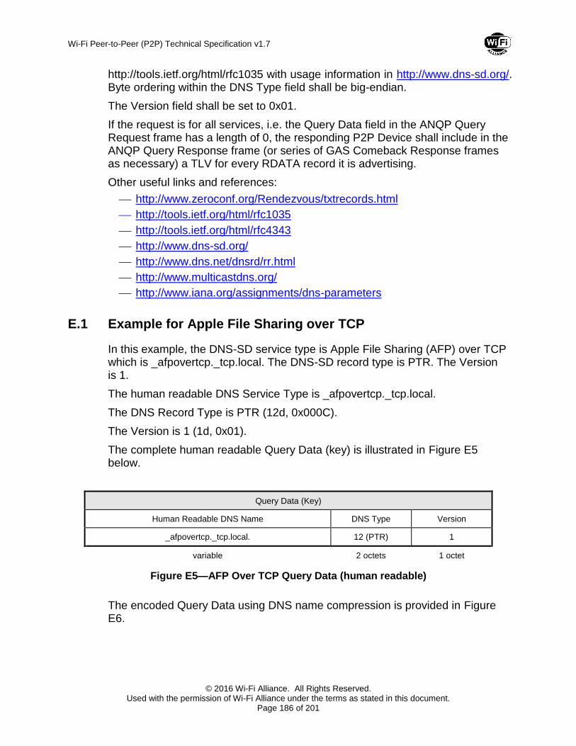
Wi-Fi Peer-to-Peer (P2P) Technical Specification v1.7
© 2016 Wi-Fi Alliance. All Rights Reserved. Used with the permission of Wi-Fi Alliance under the terms as stated in this document.
Page 186 of 201
http://tools.ietf.org/html/rfc1035 with usage information in http://www.dns-sd.org/. Byte ordering within the DNS Type field shall be big-endian.
The Version field shall be set to 0x01.
If the request is for all services, i.e. the Query Data field in the ANQP Query Request frame has a length of 0, the responding P2P Device shall include in the ANQP Query Response frame (or series of GAS Comeback Response frames as necessary) a TLV for every RDATA record it is advertising.
Other useful links and references:
http://www.zeroconf.org/Rendezvous/txtrecords.html
http://tools.ietf.org/html/rfc1035
http://tools.ietf.org/html/rfc4343
http://www.dns-sd.org/
http://www.dns.net/dnsrd/rr.html
http://www.multicastdns.org/
http://www.iana.org/assignments/dns-parameters
E.1 Example for Apple File Sharing over TCP
In this example, the DNS-SD service type is Apple File Sharing (AFP) over TCP which is _afpovertcp._tcp.local. The DNS-SD record type is PTR. The Version is 1.
The human readable DNS Service Type is _afpovertcp._tcp.local.
The DNS Record Type is PTR (12d, 0x000C).
The Version is 1 (1d, 0x01).
The complete human readable Query Data (key) is illustrated in Figure E5 below.
Query Data (Key)
Human Readable DNS Name DNS Type Version
_afpovertcp._tcp.local. 12 (PTR) 1
variable 2 octets 1 octet
Figure E5—AFP Over TCP Query Data (human readable)
The encoded Query Data using DNS name compression is provided in Figure E6.

Wi-Fi Peer-to-Peer (P2P) Technical Specification v1.7
© 2016 Wi-Fi Alliance. All Rights Reserved. Used with the permission of Wi-Fi Alliance under the terms as stated in this document.
Page 187 of 201
Query Data (Key)
Encoded and Compressed DNS Name DNS Type Version
0B 5F 61 66 70 6F 76 65 72 74 63 70 C0 0C 00 0C 01
variable 2 octets 1 octet
Figure E6—AFP Over TCP Query Data (encoded and compressed)
In this example, the DNS-SD service instance name is Example for the AFP over TCP service type. The DNS-SD record type is PTR. The Version is 1.
The human readable DNS service instance and type is Example._afpovertcp._tcp.local.
The DNS Record Type is PTR (12d, 0x000C).
The Version is 1 (1d, 0x01).
The Response Data shall contain the key (Query Data) and value (Response Data) pair. Therefore, the complete human readable Response Data is illustrated in Figure E7.
Response Data (key/value)
Human Readable DNS Name DNS Type Version RDATA
_afpovertcp._tcp.local. 12 (PTR) 1 Example._afpovertcp._tcp.local.
variable 2 octets 1 octet variable
Figure E7—AFP over TCP Response Data (human readable)
The encoded Response Data using name compression is illustrated in Figure E8.
Response Data (key/value)
Encoded and Compressed DNS Name DNS Type Version RDATA
0B 5F 61 66 70 6F 76 65 72 74 63 70 C0 0C
00 0C 01 07 45 78 61 6D 70 6C 65
C0 27
variable 2 octets 1 octet variable
Figure E8—AFP over TCP Response Data (encoded and compressed)
In this example, there is a text (TXT) record associated to the Example instance of the AFP over TCP service. Text (TXT) records are required for DNS-SD, even if there is only a null byte to show that there is no data for the service.
Therefore, in this example, the human readable text (TXT) record is null.

Wi-Fi Peer-to-Peer (P2P) Technical Specification v1.7
© 2016 Wi-Fi Alliance. All Rights Reserved. Used with the permission of Wi-Fi Alliance under the terms as stated in this document.
Page 188 of 201
The DNS Record Type is TXT (16d, 0x0010).
The Version is 1 (1d, 0x01).
The complete human readable Query Data (key) is illustrated in Figure E9 below.
Query Data (Key)
Human Readable DNS Name DNS Type Version
Example._afpovertcp._tcp.local. 16 (TXT) 1
variable 2 octets 1 octet
Figure E9—AFP Over TCP Query Data for Example (human readable)
The encoded Query Data using DNS name compression is illustrated in Figure E10.
Query Data (Key)
Encoded and Compressed DNS Name DNS Type Version
07 65 78 61 6D 70 6C 65 0B 5F 61 66 70 6F 76 65 72 74 63 70 C0 0C
00 10 01
variable 2 octets 1 octet
Figure E10—AFP Over TCP Query Data for Example (encoded and compressed)
The Response Data shall contain the key (Query Data) and value (Response Data) pair. Therefore, the complete human readable Response Data is provided in Figure E11.
Response Data (key/value)
Human Readable DNS Name DNS Type Version RDATA
Example_afpovertcp._tcp.local. 16 (TXT) 1 null
variable 2 octets 1 octet variable
Figure E11—AFP over TCP Response Data for Example (human readable)
The encoded Response Data using DNS name compression is illustrated in Figure E12.

Wi-Fi Peer-to-Peer (P2P) Technical Specification v1.7
© 2016 Wi-Fi Alliance. All Rights Reserved. Used with the permission of Wi-Fi Alliance under the terms as stated in this document.
Page 189 of 201
Response Data (key/value)
Encoded and Compressed DNS Name DNS Type Version RDATA
07 65 78 61 6D 70 6C 65 0B 5F 61 66 70 6F 76 65 72 74 63 70 C0 0C
00 10 01 00
variable 2 octets 1 octet variable
Figure E12—AFP over TCP Response Data for Example (encoded and compressed)
E.2 Example for IP Printing over TCP
In this example, the DNS-SD service type is Internet Printing Protocol over TCP which is _ipp._tcp.local. The DNS-SD record type is PTR. The version is 1.
The human readable DNS Service Type is _ipp._tcp.local.
The DNS Record Type is PTR (12d, 0x000C).
The Version is 1 (1d, 0x01).
The complete human readable Query Data (key) is illustrated in Figure E13.
Query Data (Key)
Human Readable DNS Name DNS Type Version
_ipp._tcp.local. 12 (PTR) 1
variable 2 octets 1 octet
Figure E13—IPP Over TCP Query Data (human readable)
The encoded Query Data using DNS name compression is illustrated in Figure E14.
Query Data (Key)
Encoded and Compressed DNS Name DNS Type Version
04 5F 69 70 70 C0 0C 00 0C 01
variable 2 octets 1 octet
Figure E14—IPP Over TCP Query Data (encoded and compressed)
In this example, the DNS-SD service instance name is MyPrinter for the IPP over TCP service type. The DNS-SD record type is PTR. The Version is 1.
The human readable DNS service instance and type is MyPrinter._ipp._tcp.local.
The DNS Record Type is PTR (12d, 0x000C).

Wi-Fi Peer-to-Peer (P2P) Technical Specification v1.7
© 2016 Wi-Fi Alliance. All Rights Reserved. Used with the permission of Wi-Fi Alliance under the terms as stated in this document.
Page 190 of 201
The Version is 1 (1d, 0x01).
The Response Data shall contain the key (Query Data) and value (Response Data) pair. Therefore, the complete human readable Response Data is illustrated in Figure E15.
Response Data (key/value)
Human Readable DNS Name DNS Type Version RDATA
_ipp._tcp.local. 12 (PTR) 1 MyPrinter._ipp._tcp.local.
variable 2 octets 1 octet variable
Figure E15—IPP over TCP Response Data (human readable)
The encoded Response Data using name compression is illustrated in Figure E16.
Response Data (key/value)
Encoded and Compressed DNS Name DNS Type Version RDATA
04 5F 69 70 70 C0 0C 00 0C 01 09 4D 79 50 72 69 6E 74
65 72 C0 27
variable 2 octets 1 octet variable
Figure E16—IPP over TCP Response Data (encoded and compressed)
In this example, there is a text (TXT) record associated to the MyPrinter instance of the IPP over TCP service.
The human readable text (TXT) record is: txtvers=1, pdl=application/postscript
The DNS Record Type is TXT (16d, 0x0010).
The Version is 1 (1d, 0x01).
The complete human readable Query Data (key) is illustrated in Figure E17 below.

Wi-Fi Peer-to-Peer (P2P) Technical Specification v1.7
© 2016 Wi-Fi Alliance. All Rights Reserved. Used with the permission of Wi-Fi Alliance under the terms as stated in this document.
Page 191 of 201
Query Data (Key)
Human Readable DNS Name DNS Type Version
MyPrinter_ipp._tcp.local. 16 (TXT) 1
variable 2 octets 1 octet
Figure E17—IPP Over TCP Query Data for MyPrinter (human readable)
The encoded Query Data using DNS name compression is illustrated in Figure E18.
Query Data (Key)
Encoded and Compressed DNS Name DNS Type Version
09 6D 79 70 72 69 6E 74 65 72 04 5F 69 70 70 C0 0C 00 10 01
variable 2 octets 1 octet
Figure E18—IPP Over TCP Query Data for MyPrinter (encoded and compressed)
The Response Data shall contain the key (Query Data) and value (Response Data) pair. Therefore, the complete human readable Response Data is provided in Figure E19.
Response Data (key/value)
Human Readable DNS Name DNS Type Version RDATA
MyPrinter_ipp._tcp.local. 16 (TXT) 1 txtvers=1,pdl=application/postscript
variable 2 octets 1 octet variable
Figure E19—IPP over TCP Response Data for MyPrinter (human readable)
The encoded Response Data using DNS name compression is illustrated in Figure E20 below.

Wi-Fi Peer-to-Peer (P2P) Technical Specification v1.7
© 2016 Wi-Fi Alliance. All Rights Reserved. Used with the permission of Wi-Fi Alliance under the terms as stated in this document.
Page 192 of 201
Response Data (key/value)
Encoded and Compressed DNS Name DNS Type Version RDATA
09 6D 79 70 72 69 6E 74 65 72 04 5F 69 70 70 C0 0C
00 10 01
09 74 78 74 76 65 72 73 3D 31 1A 70 64 6C 3D
61 70 70 6C 69 63 61 74 69 6F 6E 2F 70 6F 73 74
73 63 72 69 70 74
variable 2 octets 1 octet variable
Figure E20—IPP over TCP Response Data for MyPrinter (encoded and compressed)
E.3 DNS Name Compression
The DNS Name in the Query Data and Response Data are compressed using DNS Name Compression as defined in Section 4.1.4 of RFC 1035.
With traditional DNS Name Compression, the domain name is replaced with a pointer to a prior occurrence of the same name in the DNS query. For P2P SD using GAS, the pointer refers to a virtual in-memory DNS packet with two implied queries (the domain header of the packet is not used for the purposes of compression):
_tcp.local. PTR IN
_udp.local. PTR IN
Note that the domain name in the second query is one actual label (_udp) followed by a compression pointer to the second & third labels of the first query (local.). That is, the data of the virtual in-memory DNS packet is (encoded as a C string) as follows.
"\x04_tcp\x05local\x00\x00\x0C\x00\x01\x04_udp\xC0\x11\x00\x0C\x00\x01"
Again, note that the domain header of the packet is used when calculating compression pointers (offsets from the beginning of the virtual in-memory packet), but otherwise is not used.
The Resource Record (RR, refer to Section 3.2 of RFC 1035) is written starting at byte 27 of the virtual in-memory packet, which is just after the two implied queries. If possible, the RR name is compressed to the queries in the virtual in-memory packet. The two DNS Type bytes are written after the name. The two DNS Class bytes are skipped. If possible and compliant with DNS-SD practice (for example, for SRV and PTR records), the RDATA bytes are also compressed to the RR name and queries in the virtual in-memory packet.
The key is the RR name plus the two bytes of RR Type plus the single Version byte 0x01 (the Version byte is not in the virtual in-memory packet). That is, the RR Class bytes are not included in the key. The value is the RDATA bytes.
For Query Requests (which do not have RDATA), the DNS Name in the Query Data is written starting at byte 27 of the virtual in-memory packet, which is just after the two implied queries. If possible, the RR name is compressed to the
Wi-Fi Peer-to-Peer (P2P) Technical Specification v1.7
© 2016 Wi-Fi Alliance. All Rights Reserved. Used with the permission of Wi-Fi Alliance under the terms as stated in this document.
Page 193 of 201
queries in the virtual in-memory packet. The two DNS Type bytes are written after the name. The two DNS Class bytes are unused. DNS names in the key must be canonicalized to lower-case, because DNS names are case-insensitive.
The key is the DNS Name in the Query Data plus the two bytes of RR Type plus the single Version byte 0x01 (the Version byte not in the in-memory packet).
Note, not all service types have compressible RDATA. There are certain DNS service types that are compressible, such as text (TXT) service types. Text (TXT) records are not compressible, since they do not contain a DNS name. The RDATA should only be compressed for those DNS types whose RDATA is compressible per the DNS-SD specification.
E.4 Supported Service Type Hash (SSTH)
The Supported Service Type Hash is a mechanism to improve the efficiency of exchanging service information between P2P devices. The SSTH is a bitwise hash table that contains information about the service types supported by a P2P device. The SSTH has a length of 32 bytes (256 bits). A CRC-8 is computed on the Encoded and Compressed DNS Name of the Query Data (key), which results in a number between 0 – 255. In order to indicate that a service type is supported (advertising a given service), the P2P Device shall set the bit corresponding to that number in the SSTH. For example, a CRC-8 of the compressed name of a given service type (key) results in a value of 201. The 201st bit of the SSTH shall be set to 1 if the service is supported. DNS names in the key must be canonicalized to lower-case, because DNS names are case-insensitive, but the hash for the SSTH is case-sensitive. Therefore, one would get the same hit whether browsing for MyPrinter._ipp._tcp.local. or myprinter._ipp._tcp.local.
If P2P device A queries for the SSTH of P2P device B and only the n-th bit in the SSTH is set, but the service type (key) P2P device A is looking for hashes to the m-th bit (the CRC-8 of the key is m), then P2P device A knows P2P device B does not support the requested service type (key). If the service type (key) hashes to the n-th bit, then P2P device A will have to perform additional SD queries in order to confirm that requested service type (key) is supported and to get additional information (service records) about the requested service type.
The exchange of the SSTH is done using the Service Discovery mechanism (IEEE 802.11-2012 [1]) defined in this Specification.
To request the SSTH from a P2P device, the Service Discovery frame shall include a single Service Request TLV with the Service Protocol Type set to 1 (Bonjour). The Query Data shall contain the DNS Encoded name set to null value (zero length string), the DNS Type set to 0, and the version set to 0.
In response to a Service Discovery query for the SSTH, a single Service Response TLV shall contain the Service Protocol Type set to 1 (Bonjour). The Service Transaction ID is set to the value corresponding to the Service

Wi-Fi Peer-to-Peer (P2P) Technical Specification v1.7
© 2016 Wi-Fi Alliance. All Rights Reserved. Used with the permission of Wi-Fi Alliance under the terms as stated in this document.
Page 194 of 201
Transaction ID in the Service Request TLV. If the SSTH is available, the Status Code field is set to Service available (value 0 in Table 64) and the Response Data field shall contain the DNS Encoded Name is set to null value (zero length string), the DNS Type set to 0, the version set to 0, and the RDATA shall contain the corresponding SSTH for the P2P device. If the SSTH is not available, the Status Code field is set to 2 (Requested information not available) and the Response Data field shall contain a DNS Encoded Name set to a null value (zero length string), the DNS Type set to 0, the version set to 0, and the RDATA is set to a null value.

Wi-Fi Peer-to-Peer (P2P) Technical Specification v1.7
© 2016 Wi-Fi Alliance. All Rights Reserved. Used with the permission of Wi-Fi Alliance under the terms as stated in this document.
Page 195 of 201
Appendix F Recommended Practices for UPnP using Wi-Fi P2P Service Discovery
The following section provides recommended practices for using UPnP/SSDP with the service discovery mechanism defined in this Specification. In addition some UPnP service discovery examples are provided.

Wi-Fi Peer-to-Peer (P2P) Technical Specification v1.7
© 2016 Wi-Fi Alliance. All Rights Reserved. Used with the permission of Wi-Fi Alliance under the terms as stated in this document.
Page 196 of 201
Vendor-specific Content in ANQP Query Request
OUI Subtype Service Update
Indicator Length
Service Protocol Type
Service Transaction ID
Query Data
0x09 See Section
3.1.3.1 Length Table 78 Transaction ID See below
1 octet 2 octets 2 octets 1 octet 1 octet variable
Figure F1—Vendor-specific Content in ANQP Query Request
Vendor-specific Content in ANQP Query Response
OUI Subtype
Service Update
Indicator Length
Service Protocol Type
Service Transaction ID
Status Code Response Data
0x09 See Section
3.1.3.2 Length Table 78 Transaction ID Table 80 See below
1 octet 2 octets 2 octets 1 octet 1 octet 1 octet variable
Figure F2—Vendor-specific content in ANQP Query Response
Query Data
Query Version Query Value
NA NA
1 octet variable
Figure F3—Query Data
Response Data
Response Version Response Value
NA NA
1 octet variable
Figure F4—Response Data
Service Protocol Type for UPnP = 2
Query Version should always be set to 0x10 if the query values are compatible with UPnP Device Architecture 1.0. For more information, please refer to: http://www.upnp.org/specs/arch/UPnP-arch-DeviceArchitecture-v1.0.pdf. Note that version 1.1 of the UPnP Device Architecture is also compatible with version 1.0.
If Query Version is 0x10, then Query Value must contain the SSDP value of the Search Target (ST:) header of an M-SEARCH discovery request.

Wi-Fi Peer-to-Peer (P2P) Technical Specification v1.7
© 2016 Wi-Fi Alliance. All Rights Reserved. Used with the permission of Wi-Fi Alliance under the terms as stated in this document.
Page 197 of 201
Table F1 lists the defined Search Target header values.
Table F1— Query Values
Query Value Syntax Description
ssdp:all Searches for all UPnP devices and services
upnp:rootdevice Searches for all UPnP root devices
uuid:device-uuid Searches for a particular device
urn:schemas-upnp-org:device:deviceType:ver Searches for devices of the given type
urn:domain-name:device:deviceType:ver Searches for devices with a vendor-specific type
urn:schemas-upnp-org:service:serviceType:ver Searches for devices containing a service of the given type
urn:domain-name:service:serviceType:ver Searches for devices containing a vendor-specific service
Response Version should always be set to 0x10 if the response values are compatible with UPnP Device Architecture 1.0. For more information, please refer to: http://www.upnp.org/specs/arch/UPnP-arch-DeviceArchitecture-v1.0.pdf.
Response Value must contain a comma-separated list of values from the USN: headers of SSDP Discovery Response messages. If no devices matching the Query are found, the Status Code field is set to 2 (Requested information not available) and Response Value must be empty.
The rationale behind returning only the USN: header value is that the complete UPnP discovery should still take place after the IP connection is established. There would be little benefit and a lot of overhead and complexity to duplicate the entire UPnP service discovery stack over Layer 2. The USN: data in the Response Data tells the initiator that a service or UPnP device of interest is present, and it also provides the UUID of the specific device.
The UUID is useful because once the control point device is connected at the IP layer, it can direct its UPnP discovery stack to search for a device with that particular UUID using a minimal value for the SSDP MX: header. Doing this can substantially increase the performance of the UPnP discovery process.
F.1 Example 1—Search for UPnP internet gateway devices

Wi-Fi Peer-to-Peer (P2P) Technical Specification v1.7
© 2016 Wi-Fi Alliance. All Rights Reserved. Used with the permission of Wi-Fi Alliance under the terms as stated in this document.
Page 198 of 201
ANQP Query Request for UPnP Internet Gateway devices
OUI Subtype
Service Update
Indicator Length
Service Protocol
Type
Service Transaction
ID Query Data
0x09 1 Length 2 (UPnP) 1 0x10 urn:schemas-upnp-org:device:InternetGatewayDevice:1
Figure F5—Query Request for UPnP Internet Gateway Devices
ANQP Query Response for UPnP Internet Gateway devices
OUI Subtype
Service Update
Indicator Length
Service Protocol
Type
Service Transaction
ID
Status Code
Response Data
0x09 1 Length 2
(UPnP) 1 0
0x10 uuid:6859dede-8574-59ab-9332-123456789012::urn:schemas-upnp-org:device:InternetGatewayDevice:1
Figure F6—Query Response for UPnP Internet Gateway Devices
F.2 Example 2—Search for all UPnP root devices
ANQP Query Request for all UPnP root devices
OUI Subtype
Service Update
Indicator Length
Service Protocol
Type
Service Transaction
ID Query Data
0x09 1 Length 2 (UPnP) 2 0x10 upnp:rootdevice
Figure F7—Query Request for all UPnP root devices
ANQP Query Response for all UPnP root devices
OUI Subtype
Service Update
Indicator Length
Service Protocol
Type
Service Transaction
ID
Status Code
Response Data
0x09 1 Length 2 (UPnP) 2 0
0x10 uuid:6859dede-8574-59ab-9332-123456789012::upnp:rootdevice, uuid:5566d33e-9774-09ab-4822-333456785632::upnp:rootdevice
Figure F8—Query Response for all UPnP root devices
F.3 Example 3—Search for a specific device by its UUID

Wi-Fi Peer-to-Peer (P2P) Technical Specification v1.7
© 2016 Wi-Fi Alliance. All Rights Reserved. Used with the permission of Wi-Fi Alliance under the terms as stated in this document.
Page 199 of 201
ANQP Query Request for a UPnP device by its UUID
OUI Subtype
Service Update
Indicator Length
Service Protocol
Type
Service Transaction
ID Query Data
0x09 1 Length 2 (UPnP) 3 0x10 uuid:6859dede-8574-59ab-9332-123456789012
Figure F9—Query Request for a UPnP device by its UUID
ANQP Query Response for a UPnP device by its UUID
OUI Subtype
Service Update
Indicator Length
Service Protocol
Type
Service Transaction
ID
Status Code
Response Data
0x09 1 Length 2 (UPnP) 3 0 0x10 uuid:6859dede-8574-59ab-9332-123456789012
Figure F10—Query Response for a UPnP device by its UUID
F.4 Example 4—Search for all instances of a UPnP Media Server Content Directory Service
ANQP Query Request for all instances of a UPnP Media Server CDS
OUI Subtype
Service Update
Indicator Length
Service Protocol
Type
Service Transaction
ID Query Data
0x09 1 Length 2 (UPnP) 4 0x10 urn:schemas-upnp-org:service:ContentDirectory:2
Figure F11—Query Request for all instances of a UPnP Media Server CDS
ANQP Query Response for all instances of a UPnP Media Server CDS
OUI Subtype
Service Update
Indicator Length
Service Protocol
Type
Service Transaction
ID
Status Code
Response Data
0x09 1 Length 2 (UPnP) 4 0
0x10 uuid:1122de4e-8574-59ab-9322-333456789044::urn:schemas-upnp-org:service:ContentDirectory:2,uuid:5566d33e-9774-09ab-4822-333456785632::urn:schemas-upnp-org:service:ContentDirectory:2
Figure F12—Query Response for all instances of a UPnP Media Server CDS

Wi-Fi Peer-to-Peer (P2P) Technical Specification v1.7
© 2016 Wi-Fi Alliance. All Rights Reserved. Used with the permission of Wi-Fi Alliance under the terms as stated in this document.
Page 200 of 201
Appendix G Recommended Practices for Peer-to-Peer Services (P2Ps) using P2P Service Discovery
The following section provides recommended practices for using Peer-to-Peer services (P2Ps) [10] with the service discovery mechanism. In addition to existing Service Protocol Types (see Table 78 (Service Protocol Types)) a new type for P2Ps is defined. The search query shall include the exact service name or service name prefix, to find service(s) on remote side. The Service Information Request string may be zero length if it is not applicable. The result of the GAS Request may be up to 64K of application defined data, minus the mandatory overhead of the GAS protocol.
The "Service Protocol Type" field in ANQP Query Request Frame Vendor-specific Content is set to 0x0B.
Table G1 (Query Data format in ANQP Query Request Frame Vendor-Specific Content for P2Ps) illustrates the “Query Data” field format in ANQP Query Request Frame Vendor-specific Content TLV for P2Ps. Refer to Figure C4 (ANQP Query Request Frame Vendor-specific Content).
The "Service Protocol Type" field in ANQP Query Response Frame Vendor-specific Content is set to 0x0B.
Table G2 (Response Data format in ANQP Query Response Vendor-specific Content for P2Ps) illustrates the "Response Data" field format in ANQP Query Response Vendor-specific Content TLV for P2Ps. Refer to Figure C8 (ANQP Query Response Frame Vendor-specific Content Field).
Table G1 - Query Data format in ANQP Query Request Frame Vendor-Specific Content for P2Ps
Field Name Size (octets) Value Description
Service Name Length 1 0x00-0xFF Length of Service Name
Service Name Service Name Length
variable Service name or prefix of the service name being searched for extra information
Service Information Request Length
1 0x00-0xFF Length of Service Information Request
Service Information Request
variable variable UTF-8 substring to search for inside service_information

Wi-Fi Peer-to-Peer (P2P) Technical Specification v1.7
© 2016 Wi-Fi Alliance. All Rights Reserved. Used with the permission of Wi-Fi Alliance under the terms as stated in this document.
Page 201 of 201
Table G2 - Response Data format in ANQP Query Response Vendor-specific Content for P2Ps
Field Name Size (octets) Value Description
Number of Service Info Descriptor
1 variable The number of Service Info Descriptor
Service Info Descriptor(s)
Sum of all Service Info Descriptor(s)
Table G3 - Service Info Descriptor format
Field Name Size (octets) Value Description
Advertised Service Descriptor
Size of Advertised Service Descriptor
Advertised Service Descriptor in Section 4.1.26 (Advertised Service Info Attribute)
Service Status 1 0x00-0xFF 0x00 – Not Available
0x01 – Available
Else – Service Specific
Service Information Length
2 variable Length of Service Information
Service Information variable variable Application defined service information data.


![[MS-WFDPE]: Wi-Fi Display Protocol Extension...The Wi-Fi Display Protocol Extension extends the Wi-Fi Display Technical Specification [WF-DTS2.1] with a set of extensions. This protocol](https://img.pdfslide.us/doc/110x75/5ee0d668ad6a402d666bede8/ms-wfdpe-wi-fi-display-protocol-extension-the-wi-fi-display-protocol-extension.jpg)