Embed Size (px)
Citation preview

Ins
talla
tion
& O
pe
ratin
g In
stru
ctio
ns
Wi-Fi Controlled ThermostatModel: TRTWIFI
1
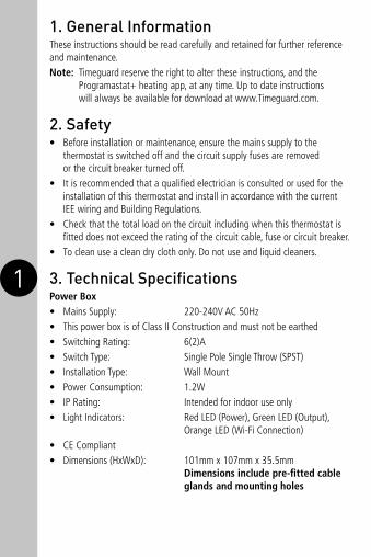
1. General InformationThese instructions should be read carefully and retained for further reference and maintenance.Note: Timeguard reserve the right to alter these instructions, and the
Programastat+ heating app, at any time. Up to date instructions will always be available for download at www.Timeguard.com.
2. Safety• Before installation or maintenance, ensure the mains supply to the
thermostat is switched off and the circuit supply fuses are removed or the circuit breaker turned off.
• It is recommended that a qualified electrician is consulted or used for the installation of this thermostat and install in accordance with the current IEE wiring and Building Regulations.
• Check that the total load on the circuit including when this thermostat is fitted does not exceed the rating of the circuit cable, fuse or circuit breaker.
• To clean use a clean dry cloth only. Do not use and liquid cleaners.
3. Technical SpecificationsPower Box• Mains Supply: 220-240V AC 50Hz• This power box is of Class II Construction and must not be earthed• Switching Rating: 6(2)A • Switch Type: Single Pole Single Throw (SPST)• Installation Type: Wall Mount • Power Consumption: 1.2W• IP Rating: Intended for indoor use only• Light Indicators: Red LED (Power), Green LED (Output),
Orange LED (Wi-Fi Connection)• CE Compliant• Dimensions (HxWxD): 101mm x 107mm x 35.5mm
Dimensions include pre-fitted cable glands and mounting holes

2 3
Thermostat• This thermostat is of Class II Construction and must not be earthed• Connection: 2 wire• Installation Type: Using either the surface mount box
supplied or a BS flush mount wall box (min 35mm depth)
• Wi-Fi Protocol: 802.11b/g/n• Network Protocol: IPv4 TCP• Frequency Range: 2.412 – 2.484 GHz • 5 Operating Modes: Permanent ON or OFF, Auto Timed,
Frost and Holiday• Programmes: 6 timed periods per day, with weekly repeats• Back Light: Yes• Operating Temperature Range: 0°C to +40°C• Set Temperature Range: Minimum +5°C to maximum +35°C• Temperature Adjustment: 0.5°C steps• Swing 0.5 or 1.0 C• CE Compliant• Dimensions (HxWxD): 90mm x 90mm x 46mm
TRTWIFI Thermostat – Front ViewThe heating
symbol will show
when heat is
demanded
The override
symbol will
show when
temperature has
been manually
changed
+/- setting
buttons
The Wi-Fi icon
will show when
the device is
connected to
the internet
The frost symbol
will show when
frost protection
mode is active
Holiday
mode icon
Auto mode
icon
5°C to 35°C set
temperature range

3 4
TRTWIFI Power Box – Front View
Red LED:
illuminates
when power is
supplied from
the mains
Orange LED: flashes
twice regularly when
connected to the
internet and pulses
when in pairing
mode. The orange
LED will flash quickly
when there is a
communication issue
Manual Output
Button: functions
only when there
is no internet
connection as an
ON/OFF button
Green LED: illuminates when
output is switched ON
TRTWIFI MAC address and ID Wi-Fi number label
Important: Do not remove this label from the side of the product.

4 5
4. Contents• 1x TRTWIFI Thermostat• 1x TRTWIFI Power Box • 1x Instruction Manual• Mounting Kit Note: All instructions are to be left with the customer
after installation
5. Installation 5.1 Ensure the mains supply is switched off and the circuit supply fuses
are removed or the circuit breaker turned off. 5.2 Disconnect the mains supply from the wiring centre.5.3 Mount the power box next to the wiring centre (where fitted),
or the boiler.5.4 Use the power box as a template to mark the position of the mounting
screws. Drill the mounting hole taking care to avoid any joists, electrical cables or water/gas pipes that may be hidden beneath the surface.
5.5 Insert the rawl plugs into the holes that have been drilled and align the power box with the mounting holes. Then insert the screws and tighten until a firm hold of the power box is ensured.
5.6 Connect the live (brown) and neutral (blue) wires on the power box to a 230V AC supply from the wiring centre, making sure the polarities match up accordingly with the wiring centre. Refer to the connection diagram (section 6) for reference.
5.7 Remove the connections from the existing thermostat from the wiring centre. If there is a neutral connection (blue) this is no longer required for the installation and must be disconnected. Refer to the connection diagram (section 6) for reference.
5.8 Connect the existing thermostat connections in the wiring centre to the two black wires from the power box flex marked boiler. These are volt free connections, and are not polarity sensitive. Refer to the connection diagram (section 6) for reference.
5.9 Connect the previously removed wires that go from the wiring centre to the thermostat to the white wires from the power box, marked thermostat. The wires are not polarity sensitive. Remove the existing thermostat if fitted. Refer to the connection diagram (section 6) for reference.
5 6
Press tab down
Remove the front plate
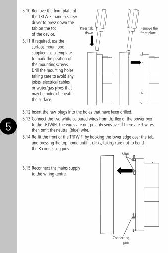
5.10 Remove the front plate of the TRTWIFI using a screw driver to press down the tab on the top of the device.
5.11 If required, use the surface mount box supplied, as a template to mark the position of the mounting screws. Drill the mounting holes taking care to avoid any joists, electrical cables or water/gas pipes that may be hidden beneath the surface.
5.12 Insert the rawl plugs into the holes that have been drilled.5.13 Connect the two white coloured wires from the flex of the power box
to the TRTWIFI. The wires are not polarity sensitive. If there are 3 wires, then omit the neutral (blue) wire.
5.14 Re-fit the front of the TRTWIFI by hooking the lower edge over the tab, and pressing the top home until it clicks, taking care not to bend the 8 connecting pins.
5.15 Reconnect the mains supply to the wiring centre.
Clips
Connecting pins

6 7
6. Connection Diagram The diagram below shows a typical thermostat wiring to a wiring centre.
The diagram below shows how the TRTWIFI would replace a typical thermostat setup. Note: Check boiler instructions before connecting.

7
IMPORTANT: If a volt free installation is required use suitable cable for your supply/load requirements in regards to the boiler.
230V 50Hz Mains Supply to Power Box Live Supply (Brown or Red) to LNeutral Supply (Blue or Black) to N
Supply/Load (Boiler)The boiler connections from the power box (black wires) are volt free and are not polarity sensitive.
TRTWIFI and Power Box ConnectionsThe thermostat connections from the power box (white wires) connect to the TRTWIFI terminals. This wiring is volt free and is not polarity sensitive.
7. SetupNote: the mobile or tablet device must be connected to a 2.4 GHz band on the router. Pairing on the 5GHz band will result with paring either timing out or being unsuccessful. Refer to your ISP (Internet Service Provider) on separating the bands if required.
7.1 Ensure your phone or tablet is connected to your local Wi-Fi network.
7.2 Download the Timeguard Programastat+ app onto your phone or tablet by searching for Timeguard on Google Play or the Apple store.

8
7.3 Install the App, and open it to the registration page.
7.4 Users must first register, and then log in to use App. First time users must use the main account log in.
Note: User names and passwords cannot contain any spaces or special characters, and must use letters and numbers only.
7.5 Then, press the + button (bottom right on phones screen to open the add devices menu.
7.6 The Wi-Fi network the mobile or tablet is connected to will be shown on the App, enter the password for the network SSID. Important – DO NOT PRESS START AS OF YET.
9 10
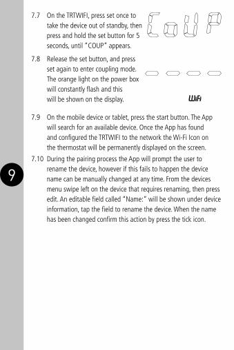
7.7 On the TRTWIFI, press set once to take the device out of standby, then press and hold the set button for 5 seconds, until “COUP” appears.
7.8 Release the set button, and press set again to enter coupling mode. The orange light on the power box will constantly flash and this will be shown on the display.
7.9 On the mobile device or tablet, press the start button. The App will search for an available device. Once the App has found and configured the TRTWIFI to the network the Wi-Fi Icon on the thermostat will be permanently displayed on the screen.
7.10 During the pairing process the App will prompt the user to rename the device, however if this fails to happen the device name can be manually changed at any time. From the devices menu swipe left on the device that requires renaming, then press edit. An editable field called “Name:” will be shown under device information, tap the field to rename the device. When the name has been changed confirm this action by press the tick icon.

10
7.11 Swipe the device name left to edit the name, and set the location. Chose the country and city nearest to your location. This will display the outside temperature on the home screen.
Note: Device names cannot contain any spaces or special characters.
8. Features of the TRTWIFI Thermostat Thermostat Manual Override• The set temperature can be overridden on the thermostat as a temporary
override until the next programme change using the + and – buttons. Mode Button• The mode button is used to change between different operating modes;
these modes include Auto, Holiday, OFF, ON & Frost protection mode. Power Box If the Wi-Fi icon is flashing,the thermostat has lost connection to the
server. Re-connection is automatic when the Wi-Fi is restored. During this period the thermostat will follow the program entered. It can be over ridden using the + and - buttons.

11 12
HELPLINE020 8450 0515
9. Features of the Android and IOS App General• The app can be accessed, and the device controlled from any accessible
Wi-Fi zone. Once Wi-Fi is set up on the device, the App can also control the TRTWIFI through 4G. The TRTWIFI must be connected to a Wi-Fi network.
• The App can be downloaded from the Google Play store or Apple Store.• There are useful programming tips and help available on the Timeguard
YouTube channel. You can access the link directly from our website www.timeguard.com or go to the YouTube home page and search ‘Timeguard’.
Device Home Screen• From log in, the user is presented with a list of devices.
Each of these has a device home screen. When a device is selected, the home screen is then shown.
Back Button
Mode
Mode entry Programme entry
Next programme
change
Outdoor temperature
Household temperature
Set temperature
Device name

12
Manual Override• The temperature can be manually over ridden, by touching on the set
temperature and selecting a new one. This will override the programmed temperature until the next programmed change. The symbol will show on the screen. To revert back to the programmed temperature, touch the symbol and the override will be cancelled.
Operating Modes• The following options are available in mode settings through the devices
home screen.

13 14
Auto: Output is controlled by the target temperature set for the day periods. The target temperature for a programmed period can be temporarily overridden using the manual override function.
Permanent OFF: Output will remain off until auto is re-enabled by the user. In this mode, manual override is disabled and programmes will not run.
Permanent ON: Output will switch on when the temperature drops below the target temperature set. Once the target temperature has been reached the output will switch OFF. This action will repeat indefinitely unless the mode has been changed.
Holiday: Output is switched off until the date entered by the user, at which time the programme schedule will default back to running as normal.
Frost Protection Mode: Output is switched off unless the room temperature drops below 5°C.
• Only one mode can be selected at any time. Permanent OFF, ON, and holiday can be cancelled by returning the App to Auto mode or by pressing the mode button on the thermostat.
Programme Entry• The App supports multiple programmed times, with an easy repeat function
for different days. Up to 6 timed periods can be added with a target temperature from 5°C to 35°C.
• Timed periods and their temperatures are programmed via the programme key on the device home page. Hold the chosen programme set (normally named default) and press edit to begin setting your timed periods for the device. Hold the chosen time or temperature down to edit the timed periods and their temperature counterparts, hold the day MTWTFSaSu to change weekly repeats, or select the – or + buttons to add or remove pages.
The default plan is: 06:00 21°C 08:00 17°C 12:00 21°C 14:00 17°C 16:30 21°C 22:30 17°C

14 15
Programme time
Active days
Set temperature
Add new days,
(7 max)
New settings
Number of
pages (dots)

15
This shows the times when a temperature change has been programmed. The thermostat will maintain the programmed temperature until the next change.
16
Quick Programming Tips• Up to 6 timed temperature periods are allowed per day.• They can be edited or deleted by holding the time or temperature.• If there are less than 6 periods, new periods can be added using the + key.• The active repeats are shown in dark blue and active days for other pages
are shown in turquoise. • Days can be selected and deselected by touching the day required. • The dots or grey squares show the number of pages, with the bold square
being the active page.• If a day is de-selected, it shows grey; this would mean that the programme
last will continue to run until the next active day with a programme takes over.
• If there are grey days, a new page can be added using the + page button. If there are no grey days, new pages cannot be added because all the days would be active on one of the pages from that programme set.
• If individual day programming is required, this can be achieved by having only one active day per page until no additional pages can be added. (Page 1 M, Page 2 Tu, Page 3 W, Page 4 Th) etc.
Note: On exiting programming, any days that are grey will be deleted. Days cannot be left inactive. If a day is missing, the last temperature set will be active until the next programmed day.
Resetting the Thermostat• Put the thermostat into couple mode, (see page 8). Press + or - to see the
following menu options; Couple, Time entry, programming, copy, technical, and reset. Press set to select.
• Technical can be used to re-calibrate the displayed temperature.• It is recommended that the Programastat+ App is used to perform all
programming operations, but changes made here at the thermostat will be reflected in the App on your phone.

17
Advanced Settings
The advanced settings menu can be found on the mode settings page relevant to the user’s device and allows the user to do the following
• Users: Allows the main account holder to add additional users know as sub account users. Sub-account users can manipulate the control aspects of the TRTWIFI but will not be able to delete the device from the main holders account. Sub-account users must register via the user’s option in the advanced settings menu while the main account holder is logged in, this way the App will register any sub-account user to the main account holders TRTWIFI device.
IMPORTANT Sub-account users must not register via the registration screen when they download the App, this will result in creating a main account.
• Controls: Allows the user to change the temperature swing between 0.5 and 1.0, and turn on the optimum start function and proportional control function.
• App download: Allows the user to check which version of the App they are using and check for updates. This feature is only available on the Android version of the App. IOS users must update the App via the Apple Store.
• User manual: Provides links to our website, the relevant instructions and to our YouTube channel.
• About: Provides the company address and contact details for any problems with the unit.
• Config devices: Allows the user to change the router or extension the device is connected to.
• Time format: Allows the user to change the time format between a 12/24 hour clock.
• Privacy policy: Directs the user to the Timeguard privacy policy page on our website.

18
3 Year GuaranteeIn the unlikely event of this product becoming faulty due to defective material or manufacture within 3 years of the date of purchase, please return it to your supplier in the first year with proof of purchase and it will be replaced free of charge. For the second and third years or any difficulty in the first year telephone the helpline on 020 8450 0515.
Note: A proof of purchase is required in all cases. For all eligible replacements (where agreed by Timeguard) the customer is responsible for all shipping/postage charges outside of the UK. All shipping costs are to be paid in advance before a replacement is sent out.

Zerofour – April 201867.058.619 (Issue 1)
Timeguard Limited. Victory Park, 400 Edgware Road,
London NW2 6ND Sales Office: 020 8452 1112
or email [email protected]
For a product brochure please contact:
HELPLINE020 8450 0515
or email [email protected]
www.timeguard.com
Qualified Customer Support Co-ordinators will be on-line to assist in resolving your query.
If you experience problems, do not immediately return the unit to the store.
Telephone the Timeguard Customer Helpline;