Embed Size (px)
Citation preview
www.andersonpower.com All Data Subject To Change Without Notice
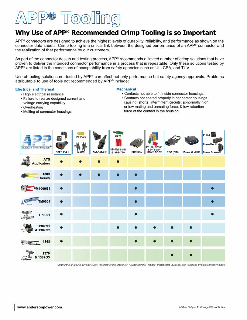
Why Use of APP® Recommended Crimp Tooling is so ImportantAPP® connectors are designed to achieve the highest levels of durability, reliability, and performance as shown on the connector data sheets. Crimp tooling is a critical link between the designed performance of an APP® connector and the realization of that performance by our customers.
As part of the connector design and testing process, APP® recommends a limited number of crimp solutions that have proven to deliver the intended connector performance in a process that is repeatable. Only these solutions tested by APP® are listed in the conditions of acceptability from safety agencies such as UL, CSA, and TUV.
Use of tooling solutions not tested by APP® can affect not only performance but safety agency approvals. Problems attributable to use of tools not recommended by APP® include:
Electrical and Thermal • High electrical resistance • Failure to realize designed current and voltage carrying capability • Overheating • Melting of connector housings
Mechanical • Contacts not able to fit inside connector housings. • Contacts not seated properly in connector housings causing: shorts, intermittent circuits, abnormally high or low mating and unmating force, & low retention force of the contact in the housing.
www.andersonpower.comAll Data Subject To Change Without Notice
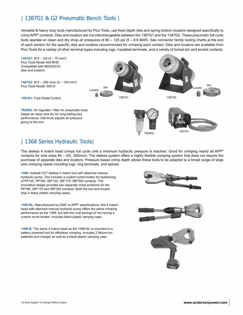
| 1387G1 & G2 Pneumatic Bench Tools |
Versatile & heavy duty tools manufactured by Pico Tools, use fixed depth dies and spring bottom locators designed specifically to crimp APP® contacts. Dies and locators are not interchangeable between the 1387G1 and the 1387G2. These pneumatic full cycle tools operate on clean and dry shop air pressures of 80 – 125 psi (5 – 8.6 BAR). See connector family tooling charts at the end of each section for the specific dies and locators recommended for crimping each contact. Dies and locators are available from Pico Tools for a variety of other terminal types including lugs, insulated terminals, and a variety of turned pin and socket contacts.
1387G1: #12 – 2/0 (4 – 70 mm²) Pico Tools Model 400-BHD Compatible with M22520/23 dies and locators
1387G2: #12 – 250 mcm (4 – 120 mm²)Pico Tools Model: 500-D
1391G1: Foot Pedal Control
TA0002: Air regulator / filter for pneumatic tools. Keeps air clean and dry for long lasting tool performance. Dial knob adjusts air pressure going to the tool.
| 1368 Series Hydraulic Tools|
The dieless 4 indent head crimps full cycle until a minimum hydraulic pressure is reached. Good for crimping nearly all APP® contacts for wire sizes #4 – 4/0, 300mcm. The dieless system offers a highly flexible crimping system that does not require the purchase of separate dies and locators. Pressure based crimp depth allows these tools to be adapted to a broad range of large wire crimping needs including lugs, ring terminals, and splices.
1368: Hubbell VC7 dieless 4 indent tool with attached manual hydraulic pump. Tool includes a custom turret locator for positioning of PP120, PP180, SB®120, SB®175, SB®350 contacts. The innovative design provides two separate crimp positions for the PP180, SB®175 and SB®350 contacts. Both the tool and locator ship in black plastic carrying cases.
1368-NL: Manufactured by DMC to APP® specifications, this 4 indent head with attached manual hydraulic pump offers the same crimping performance as the 1368, but with the cost savings of not having a custom turret locator. Includes black plastic carrying case.
1368-B: The same 4 indent head as the 1368-NL is mounted to a battery powered tool for effortless crimping. Includes 2 lithium-ion batteries and charger as well as a black plastic carrying case.
1391G1TA0002
1387G1 1387G2
DieLocator
DieLocator
www.andersonpower.com All Data Subject To Change Without Notice
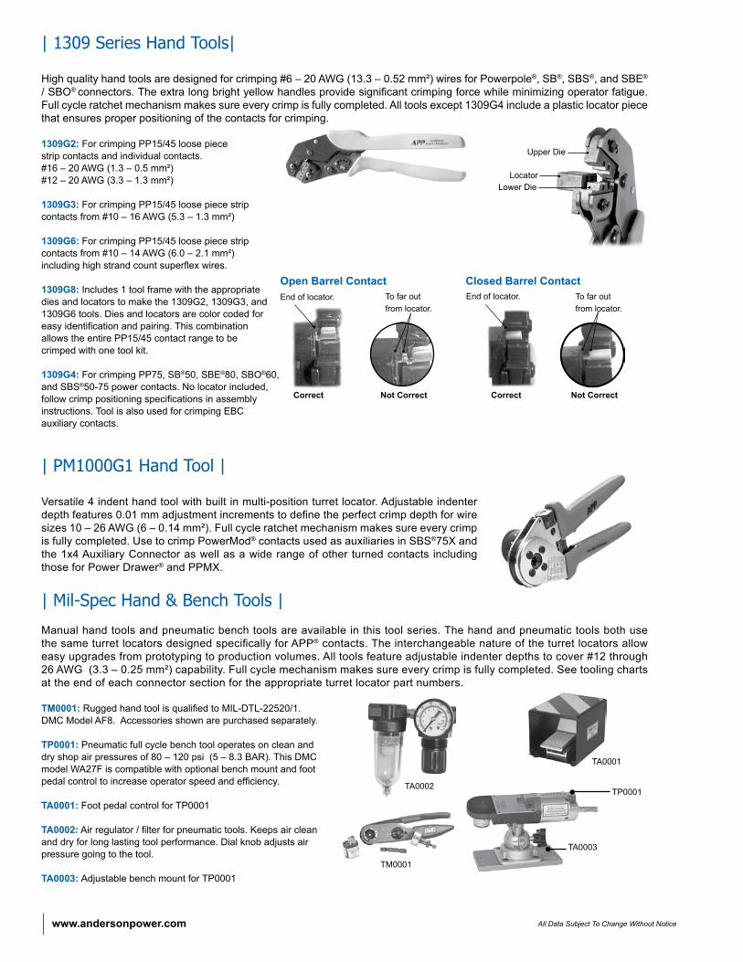
| 1309 Series Hand Tools|
High quality hand tools are designed for crimping #6 – 20 AWG (13.3 – 0.52 mm²) wires for Powerpole®, SB®, SBS®, and SBE® / SBO® connectors. The extra long bright yellow handles provide significant crimping force while minimizing operator fatigue. Full cycle ratchet mechanism makes sure every crimp is fully completed. All tools except 1309G4 include a plastic locator piece that ensures proper positioning of the contacts for crimping.
1309G2: For crimping PP15/45 loose piece strip contacts and individual contacts. #16 – 20 AWG (1.3 – 0.5 mm²) #12 – 20 AWG (3.3 – 1.3 mm²)
1309G3: For crimping PP15/45 loose piece strip contacts from #10 – 16 AWG (5.3 – 1.3 mm²)
1309G6: For crimping PP15/45 loose piece strip contacts from #10 – 14 AWG (6.0 – 2.1 mm²) including high strand count superflex wires.
1309G8: Includes 1 tool frame with the appropriate dies and locators to make the 1309G2, 1309G3, and 1309G6 tools. Dies and locators are color coded for easy identification and pairing. This combination allows the entire PP15/45 contact range to be crimped with one tool kit.
1309G4: For crimping PP75, SB®50, SBE®80, SBO®60, and SBS®50-75 power contacts. No locator included, follow crimp positioning specifications in assembly instructions. Tool is also used for crimping EBC auxiliary contacts.
| PM1000G1 Hand Tool |
Versatile 4 indent hand tool with built in multi-position turret locator. Adjustable indenter depth features 0.01 mm adjustment increments to define the perfect crimp depth for wire sizes 10 – 26 AWG (6 – 0.14 mm²). Full cycle ratchet mechanism makes sure every crimp is fully completed. Use to crimp PowerMod® contacts used as auxiliaries in SBS®75X and the 1x4 Auxiliary Connector as well as a wide range of other turned contacts including those for Power Drawer® and PPMX.
| Mil-Spec Hand & Bench Tools |
Manual hand tools and pneumatic bench tools are available in this tool series. The hand and pneumatic tools both use the same turret locators designed specifically for APP® contacts. The interchangeable nature of the turret locators allow easy upgrades from prototyping to production volumes. All tools feature adjustable indenter depths to cover #12 through 26 AWG (3.3 – 0.25 mm²) capability. Full cycle mechanism makes sure every crimp is fully completed. See tooling charts at the end of each connector section for the appropriate turret locator part numbers.
TM0001: Rugged hand tool is qualified to MIL-DTL-22520/1. DMC Model AF8. Accessories shown are purchased separately.
TP0001: Pneumatic full cycle bench tool operates on clean and dry shop air pressures of 80 – 120 psi (5 – 8.3 BAR). This DMC model WA27F is compatible with optional bench mount and foot pedal control to increase operator speed and efficiency.
TA0001: Foot pedal control for TP0001
TA0002: Air regulator / filter for pneumatic tools. Keeps air clean and dry for long lasting tool performance. Dial knob adjusts air pressure going to the tool.
TA0003: Adjustable bench mount for TP0001
Upper Die
LocatorLower Die
TA0001
TP0001
TA0003
TA0002
Open Barrel Contact Closed Barrel ContactEnd of locator. To far out
from locator.End of locator. To far out
from locator.
Correct Not Correct Correct Not Correct
TM0001
www.andersonpower.comAll Data Subject To Change Without Notice
| Press and Applicator Tools |
Anderson Power Products®, in partnership with Application Tooling Solutions, has engineered a line of application tooling for APP®’s reeled contacts. All applicators have been designed to meet or exceed UL requirements. See connector family tooling charts at the end of each section for the specific press, air feed kit, and applicator recommended for crimping each contact.
• Designed Specifically For APP® Contacts Provides crimps that meet or exceed UL requirements
• World-Wide On-Site Service Provided through ATS’s extensive field service network
• Mini-Style Applicators Can Be Adapted To Most Existing Presses AMP, K & T presses, Kenco presses, and most other manufacturers
• Contact ATS Directly to Purchase or Lease Tooling
P.O. Box 6780, Harrisburg, PA 17112 USA T:877-671-2955 F:717-810-2862 www.applicationtooling.com
| Crimping Technical Reference |
Crimping, Soldering, and Assembly Best Practices. Instructions for proper assembly are available for each connector and should be followed. These best practices are for reference only.
Stripping Wire InsulationProblems with cable harness and connector systems often begin with improper or accidental cutting of wire strands when stripping wire insulation. Each strand is important, and all of them must be included in the contact barrel to avoid unnecessary hot spots during later operation. When removing insulation, position a sharp blade at a right angle and apply a steady controlled pressure cutting only the cable insulation and not the copper wire strands. Wires should be stripped to the lengths specified in the specific connector assembly instruction.
Cleaning Copper WireCopper oxide, a non-conductive material accumulates on copper wires exposed to oxygen and moisture. Aged and badly tarnished copper wire needs to be thoroughly cleaned to realize the rated performance of the connector and wire. Heavy oxidation can be scraped off with a stiff wire brush that penetrates the entire bundle and cleans every strand. For light surface oxidation a 3M Scotch Bright™ pad is recommended. The wires are ready for insertion into the contact barrel when they are burnished to their original bright copper finish. Contact barrels are lined with silver or tin plating to assure consistently high conductivity which will be reduced if the barrel is crimped around aged or tarnished wire.
CrimpingAPP® connectors are designed to achieve the highest levels of durability, reliability, and performance as shown on the connector data sheets. Crimp tooling is a critical link between the designed performance of an APP® connector and the realization of that performance by our customers.
As part of the connector design and testing process, APP® recommends a limited number of crimp solutions that have proven to deliver the intended connector performance in a process that is repeatable. Only these solutions tested by APP® are listed in the conditions of acceptability from safety agencies such as UL, CSA, and TUV.
Use of tooling solutions not tested by APP® can affect not only performance but also safety agency approvals. Problems attributable to use of tools not recommended by APP® include:
Electrical and Thermal • High electrical resistance • Failure to realize designed current and voltage carrying capability • Overheating • Melting of connector housings
Mechanical • Contacts not able to fit inside connector housings. • Contacts not seated properly in connector housings causing: shorts, intermittent circuits, abnormally high or low mating and unmating force, & low retention force of the contact in the housing
www.andersonpower.com All Data Subject To Change Without Notice
Soldering The alternative to crimping is to solder all cable strands within the contact barrel. When using an open flame, make sure that you are not in an area where explosive gasses are present. The right proportion of solder is essential if this procedure is employed. Use a quality 60/40 solder (60 percent tin, 40 percent lead) in wire form with a rosin flux core. Cable strands should be separately fluxed with rosin paste, and the contact should be held in a vise with the barrel end facing up. Apply heat to the outside of the barrel while the solder flows in beside the wire strands.
Here are some things to avoid when soldering: A. Don’t use too much solder, to the point that it flows out of the contact barrel. B. Don’t allow flux or solder on the outside of the contact. This will interfere with contact mounting within the installation or with the contact connection to a mating connector. C. Don’t overheat and cause excessive solder to “wick” up into the cable and stiffen it. This could interfere with contact flexibility when connectors are mated. D. Don’t solder when contact is in the connector housing. Solder away from the housing and then insert the contact into the housing after it has cooled.
NOTE: Underwriters Laboratories (UL) requires the use of a cable clamp for soldered connections to unsupported wires.
| Determining If A Good Crimp Has Been Made |
1. Assure the correct wire size and type is used for the specific contact being crimped.
2. Follow the assembly instructions for the connector. Special attention should be paid to wire preparation and stripping.
3. Use the correct application tooling as recommended by Anderson Power Products® (tool, die, & locator).
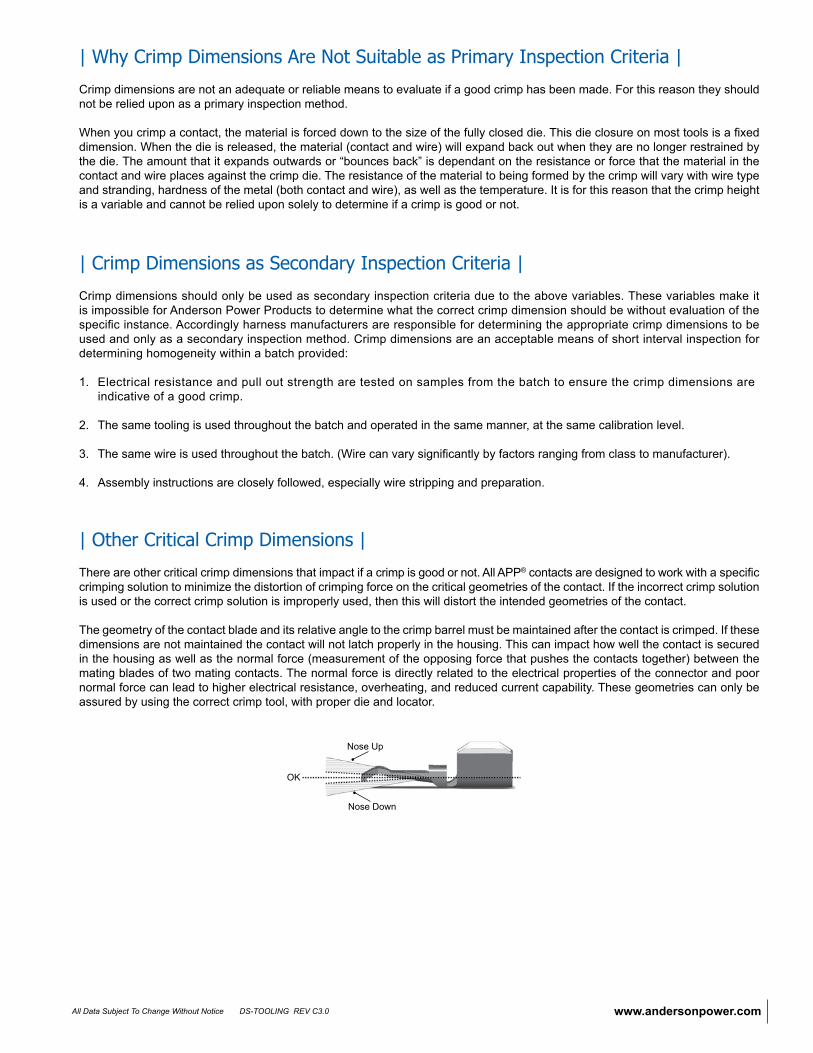
4. Make several crimps for testing, and record crimp dimensions in both “x” and “y” planes.
5. Test the electrical resistance across a mated pair of connectors to the standard of the information provided on the data sheet. a. The electrical resistance values should be similar to (or less than) what we publish for that connector in our catalogs. Please see the “Avg. Mated Contact Resistance” on the data sheet for the specific connector.
6. Test the pull out strength per the table to the right. a. To achieve the electrical performance published in our literature the pull out values at minimum should meet the UL 486A values for the wire size being used. The first column (lower value) pull out is the minimum per UL486A. The second column is what APP tries to achieve when designing our crimp solutions. Any force within this range is acceptable. 7. If crimps are within electrical and mechanical specifications then the crimp dimensions are suitable to be used as a secondary inspection criteria.
22 8 - 12 3.6 - 5.4
20 13 - 16 5.9 - 7.3
18 20 - 30 9.1 - 13.6
16 30 - 40 13.6 - 18.1
14 50 - 60 22.7 - 27.2
12 70 - 85 31.8 - 38.6
10 80 - 125 36.3 - 56.7
8 90 - 180 40.8 - 81.6
6 100 - 200 45.4 - 90.7
4 140 - 280 63.5 - 127
3 160 - 320 72.3 - 145.1
2 180 - 360 81.6 - 163.3
1 200 - 400 90.7 - 181.4
1/0 250 - 500 113.4 - 226.8
2/0 300 - 600 136.1 - 272.2
3/0 350 - 700 158.8 - 317.5
4/0 450 - 775 204.1 - 351.5250 500 - 800 226.8 - 362.9
300 550 - 800 249.5 - 362.9
Wire Size AWG or MCM
Contact Retention Force Range
Contact Retention Force Range
Lbf kgf
www.andersonpower.comAll Data Subject To Change Without Notice
| Why Crimp Dimensions Are Not Suitable as Primary Inspection Criteria |
Crimp dimensions are not an adequate or reliable means to evaluate if a good crimp has been made. For this reason they should not be relied upon as a primary inspection method.
When you crimp a contact, the material is forced down to the size of the fully closed die. This die closure on most tools is a fixed dimension. When the die is released, the material (contact and wire) will expand back out when they are no longer restrained by the die. The amount that it expands outwards or “bounces back” is dependant on the resistance or force that the material in the contact and wire places against the crimp die. The resistance of the material to being formed by the crimp will vary with wire type and stranding, hardness of the metal (both contact and wire), as well as the temperature. It is for this reason that the crimp height is a variable and cannot be relied upon solely to determine if a crimp is good or not.
| Crimp Dimensions as Secondary Inspection Criteria |
Crimp dimensions should only be used as secondary inspection criteria due to the above variables. These variables make it is impossible for Anderson Power Products to determine what the correct crimp dimension should be without evaluation of the specific instance. Accordingly harness manufacturers are responsible for determining the appropriate crimp dimensions to be used and only as a secondary inspection method. Crimp dimensions are an acceptable means of short interval inspection for determining homogeneity within a batch provided:
1. Electrical resistance and pull out strength are tested on samples from the batch to ensure the crimp dimensions are indicative of a good crimp.
2. The same tooling is used throughout the batch and operated in the same manner, at the same calibration level.
3. The same wire is used throughout the batch. (Wire can vary significantly by factors ranging from class to manufacturer).
4. Assembly instructions are closely followed, especially wire stripping and preparation.
| Other Critical Crimp Dimensions |
There are other critical crimp dimensions that impact if a crimp is good or not. All APP® contacts are designed to work with a specific crimping solution to minimize the distortion of crimping force on the critical geometries of the contact. If the incorrect crimp solution is used or the correct crimp solution is improperly used, then this will distort the intended geometries of the contact.
The geometry of the contact blade and its relative angle to the crimp barrel must be maintained after the contact is crimped. If these dimensions are not maintained the contact will not latch properly in the housing. This can impact how well the contact is secured in the housing as well as the normal force (measurement of the opposing force that pushes the contacts together) between the mating blades of two mating contacts. The normal force is directly related to the electrical properties of the connector and poor normal force can lead to higher electrical resistance, overheating, and reduced current capability. These geometries can only be assured by using the correct crimp tool, with proper die and locator.
Nose Up
Nose Down
OK
DS-TOOLING REV C3.0