Embed Size (px)
Citation preview
1
Why fuel cell based trucks will replace the Diesel engine – a thermodynamic feasibility study
Final report, REU-NSF Site. In Chicago, Illinois, May 28- August 2, 2002
Orlando Rodriguez
Advisor: Andreas A. Linninger Laboratory for Product and Process Design
Department of Chemical Engineering, University of Illinois at Chicago e-mail: {orodri7, linninge} @UIC.edu

2
TABLE OF CONTENTS:
Abstract: …………………………………………………………………………………………… 3
Introduction and Background: …………………………………………………………………...
4
1 Theory: …………………………………………………………………………………………... 1.1 Estimating horsepower demand based in weight difference …………….………………
1.2 Estimation of fuel consumption due to difference in weight ……………………………
7 7 8
2 Results: ………………………………………………………………………………………….. 2.1 Differences between a diesel engine truck and a fuel cell truck…………………………. 2.1a Diesel engine truck characteristics ………………………………………………….. 2.1b Fuel cell truck characteristics, pure hydrogen fuel .……………………………….. 2.1c Fuel cell truck characteristics, with reformer ……………………………………… 2.1d Comparison …………………………………………………………………………...
2.2 Determining horsepower demand due to weight difference ……………………………. 2.3 Fuel consumption ………………………………………………………………………….. 2.3a Fuel consumption of diesel truck ………………………………………….………… 2.3b Fuel consumption of fuel cell truck, Pure hydrogen approach …………………… 2.3c Fuel consumption, fuel cell truck with reformer …………………………………...
11 11 11 12 13 13 15 17 17 19 20
3 Conclusion and Significance: ……………………………………………………………………
23
3
Abstract:
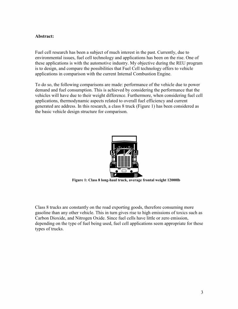
Fuel cell research has been a subject of much interest in the past. Currently, due to environmental issues, fuel cell technology and applications has been on the rise. One of these applications is with the automotive industry. My objective during the REU program is to design, and compare the possibilities that Fuel Cell technology offers to vehicle applications in comparison with the current Internal Combustion Engine. To do so, the following comparisons are made: performance of the vehicle due to power demand and fuel consumption. This is achieved by considering the performance that the vehicles will have due to their weight difference. Furthermore, when considering fuel cell applications, thermodynamic aspects related to overall fuel efficiency and current generated are address. In this research, a class 8 truck (Figure 1) has been considered as the basic vehicle design structure for comparison.
Figure 1: Class 8 long-haul truck, average frontal weight 12000lb
Class 8 trucks are constantly on the road exporting goods, therefore consuming more gasoline than any other vehicle. This in turn gives rise to high emissions of toxics such as Carbon Dioxide, and Nitrogen Oxide. Since fuel cells have little or zero emission, depending on the type of fuel being used, fuel cell applications seem appropriate for these types of trucks.
4
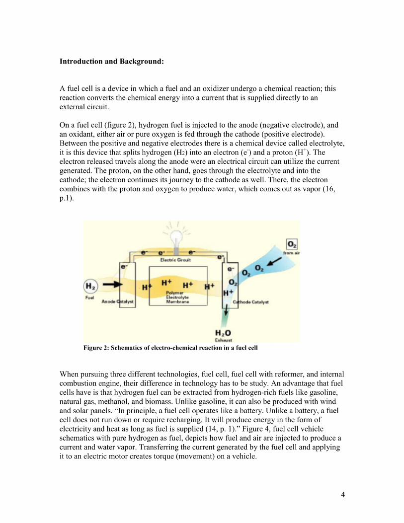
Introduction and Background: A fuel cell is a device in which a fuel and an oxidizer undergo a chemical reaction; this reaction converts the chemical energy into a current that is supplied directly to an external circuit. On a fuel cell (figure 2), hydrogen fuel is injected to the anode (negative electrode), and an oxidant, either air or pure oxygen is fed through the cathode (positive electrode). Between the positive and negative electrodes there is a chemical device called electrolyte, it is this device that splits hydrogen (H2) into an electron (e-) and a proton (H+). The electron released travels along the anode were an electrical circuit can utilize the current generated. The proton, on the other hand, goes through the electrolyte and into the cathode; the electron continues its journey to the cathode as well. There, the electron combines with the proton and oxygen to produce water, which comes out as vapor (16, p.1).
Figure 2: Schematics of electro-chemical reaction in a fuel cell When pursuing three different technologies, fuel cell, fuel cell with reformer, and internal combustion engine, their difference in technology has to be study. An advantage that fuel cells have is that hydrogen fuel can be extracted from hydrogen-rich fuels like gasoline, natural gas, methanol, and biomass. Unlike gasoline, it can also be produced with wind and solar panels. “In principle, a fuel cell operates like a battery. Unlike a battery, a fuel cell does not run down or require recharging. It will produce energy in the form of electricity and heat as long as fuel is supplied (14, p. 1).” Figure 4, fuel cell vehicle schematics with pure hydrogen as fuel, depicts how fuel and air are injected to produce a current and water vapor. Transferring the current generated by the fuel cell and applying it to an electric motor creates torque (movement) on a vehicle.

5
Fuel tank, H2 Water
Hydrogen
Fuel Cell Current Electric Motor
Figure 4: Fuel cell vehicle schematics, pure hydrogen approach As seen on figure 5, fuel cell vehicles could also relied on an onboard fuel reformer to operate on other fuel. “A fuel cell system which includes a “fuel reformer” can utilize the hydrogen from any hydrocarbon fuel – from natural gas to methanol, and even gasoline. Since the fuel cell relies on chemistry and not combustion, emission … would still be much smaller then emissions from the cleanest fuel combustion process (14, p. 1).” Reformer
Fuel tank Hydrogen
Fuel
Fuel Cell Current Water Electric Motor
Figure 5: Fuel cell vehicle schematics with reformer exhaust depends on fuel being used
Fuel supplier
Air
Exhaust, no emission
Fuel supplier
Exhaust
Air
Fuel Gasoline Exhaust N2, CO2
H2O, and small concentrations of CO.
Figure 3: Fuel cell car
6
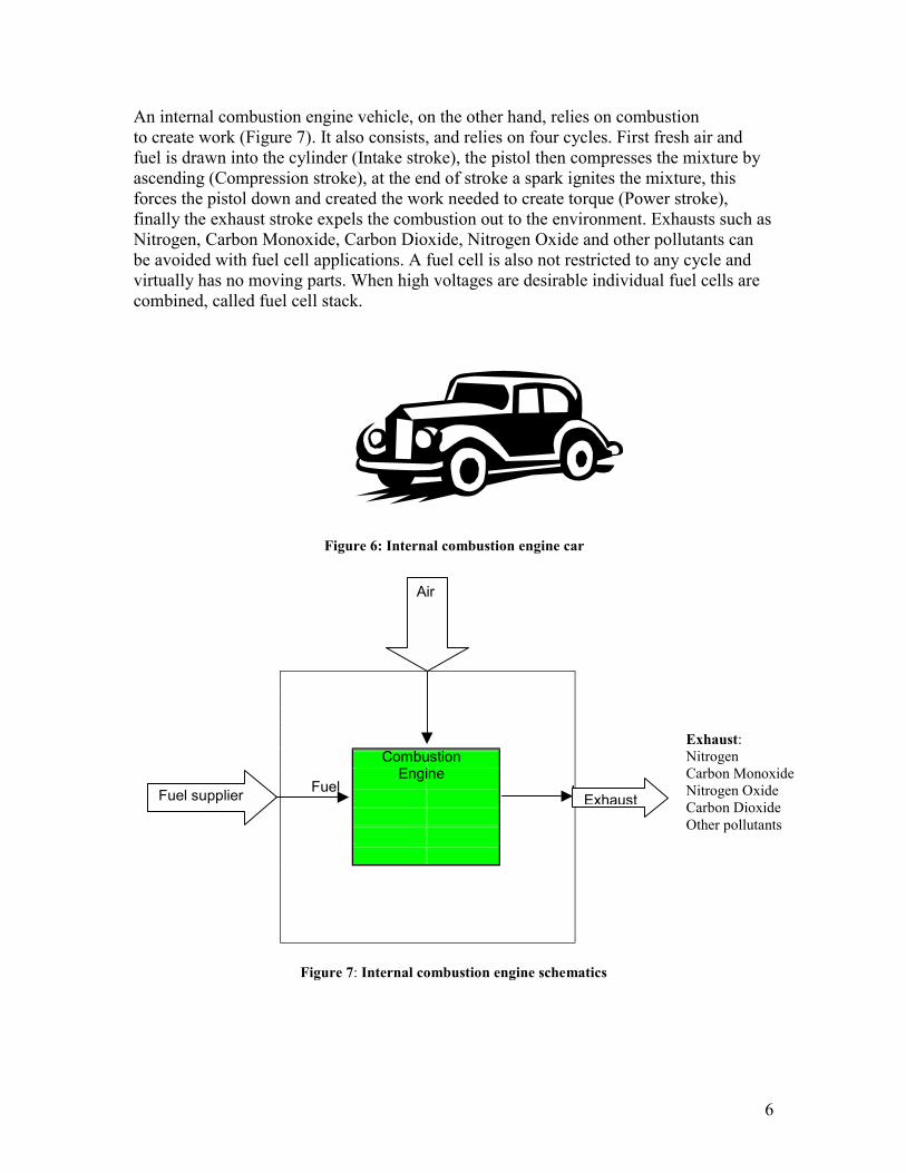
An internal combustion engine vehicle, on the other hand, relies on combustion to create work (Figure 7). It also consists, and relies on four cycles. First fresh air and fuel is drawn into the cylinder (Intake stroke), the pistol then compresses the mixture by ascending (Compression stroke), at the end of stroke a spark ignites the mixture, this forces the pistol down and created the work needed to create torque (Power stroke), finally the exhaust stroke expels the combustion out to the environment. Exhausts such as Nitrogen, Carbon Monoxide, Carbon Dioxide, Nitrogen Oxide and other pollutants can be avoided with fuel cell applications. A fuel cell is also not restricted to any cycle and virtually has no moving parts. When high voltages are desirable individual fuel cells are combined, called fuel cell stack.
Figure 7: Internal combustion engine schematics
Combustion Engine
Air
ExhaustFuel supplier Fuel
Exhaust: Nitrogen Carbon Monoxide Nitrogen Oxide Carbon Dioxide Other pollutants
Figure 6: Internal combustion engine car

7
1 Theory: To study the performance between two possible fuel cell technologies in comparison with the internal combustion engine, four steps are required.
!"First, the equations that will be needed for steps three and four need to be derived.
!"Second, the differences in weight between a diesel engine truck and fuel cell trucks have to be considered. This is done by first considering only the weight of the parts that will be affected the most when applying fuel cell technology.
!"Third, once the weight of each truck has been estimated and a comparison has been made, certain constraints such as cruising speed and distance travel will be imposed to determine the power demand.
!"Fourth, once the power demand is known, fuel and energy consumption can be determined by considering the mechanical efficiency and by applying some thermodynamic calculations.
Figure 8: Free body diagram of class 8 truck A good way to compare the mechanical efficiency of different vehicles is by drawing a free body diagram (Figure 8). The free body diagram allows for comparisons to be made for vehicles that operate either at different or similar conditions. Such conditions include the stiffness of a hill, the drag created by wind resistance or their different in weight. Here, only the difference in weight will be considered, since it is the affects of weight difference by fuel cell applications that is of most interest. In other words, the vehicles will be exposed to similar operating conditions to study the affects that weight differences has on the performance of the vehicles. 1.1 Estimating horsepower demand based on weight difference To obtain the horsepower demand, the weight of the vehicle will be considered in conjunction with other external forces. Such forces include drag, load, and friction. The equations of motion can be derived by summing all the forces in the x-direction (Σ Fx ) as indicated in the free body diagram (figure 8). At constant speed (no acceleration) equation 1 is derived. From the equation of motion (equation 1) we solve for the frictional coefficient (Fr), since it is friction that requires or demands energy to be put in to create movement on the vehicle. Once the frictional constant is known from equation 2, the power equation (equation 3) can be use so that a comparison can be made between
mg V
Fr
D
JN
X
y
Φ
Φ Load
8
the horsepower demand of each vehicle. Pout is referring to as the horsepower demand that needs to be delivered outside the system to create motion. Σ Fx = ma = 0 (no acceleration) = Fr – D – (sinΦ)mg = 0 (1) Fr = D + (sinΦ)mg (2) By combining the equation of motion with the power equation we arrive to the following expression (equation 4). Were Fr is my friction, V is the cruising velocity, D is my drag, m is the mass of the vehicle, g is the force of gravity, and Φ is the angle of inclination. Pout = Fr* V (3) Pout = (D + (sinΦ)mg)* V (4) It becomes clear from equation 1 that if both vehicles were exposed to similar operating conditions, the power demand from the engine would greatly depend on the weight of the vehicle. 1.2 Estimation of fuel consumption due to difference in weight As explained before, Pout is the power that the engine delivers in order to overcome friction created by other external forces acting on the body. In order to supply this power (Pout) we need to provide our engine or electric motor with a certain amount of power, Pin. This power in is related to the mechanical efficiency of the engine; therefore we can use our previous information to determine the power that needs to be supply to the engine or electric motor. This information will also help in determining the amount of fuel that needs to be supplied.
Table 1: Efficiencies Mechanical Efficiencies
Electric motor 90% Diesel engine 35%
For diesel engines, “ Thermal efficiency of 54% have been demonstrated by single cylinder engine testing of advanced diesel engine concepts developed under Department of Energy funding (21, p. 1).” As seen on table 1, we have decided to use a diesel engine efficiency of 35%, which for today’s standards is considered to be a maximum efficiency. An electric motor on the other hand, with an average efficiency of 90%, looses only 10% of the power delivered (20, p. 2). The electric motor is more efficient because it does not rely on combustion to use this power; it just uses the electric current. An electric motor can actually have a better efficiency, but not worse, if better lubrication is imposed to reduce friction.
The efficiency of the engine or electric motor is related to the power supply out of the system (Pout) by the law of Mechanical Efficiency (equation 5).
9
e (efficiency) = Pout / Pin (5) Pin = Pout / e (6) On equation 5, Pin is the power supply to the engine or electric motor. It is this power that is later used, on a diesel engine through combustion, and creates the horsepower demand (Pout). Pin (Diesel Engine) = Pout / 0.35 (7) Pin (Electric Motor) = Pout / 0.90 (8) Knowing the power supply (Pin) from equations 7 and 8, allows to calculate the rate of fuel consumption.
#" For the diesel truck engine the power supply to the engine (Pin) and the fuel Heating Value (HV) for gasoline need to be considered. Once these two values are know the rate of fuel consumption can be estimated.
[X gal / hr] * [HV] = [Pin ] (9) [X] = [Pin ] / [HV] gal / hr (10)
Pin can be determined from equation 7, and the HV for gasoline can be obtained from reference 9, page 2.
#" For the fuel cell trucks, the amount of power that needs to be supplied to the electric motor needs to be known first. Since the power the electric motor demands is the power the fuel cells needs to supply.
[Pin kJ / s] * [trip m] * [ hr / Speed m] * [3600 s / hr] = Energy Needed J (11)
Equation 11 computes the amount of energy that the fuel cell need to deliver which is proportional to the power supply (Pin), the cruising speed, and the distance traveled. Once the energy needed is known, fuel consumption of hydrogen gas can be determined by dividing by the Heating Value of the reaction shown below for Proton Exchange Membrane Fuel Cells (PEMFC). The HV can be calculated by using the standard molar enthalpies, and Hess’s Law (7, p. 105-109). From the reaction for PEMFC H2 + 1/2O2 H2 O The standard enthalpy of reaction is ΔH° = H° H2 O(g) - H° H2 (g) – H° ½ O2(g)

10
The standard molar enthalpy for O2(g) and H2(g) is zero and for H2O(g), at standard temperature and pressure, is –241.8 kJ/mol, negative means exothermic(5, p. 847). The standard molar enthalpy for the above reaction is.
ΔH° = -241.8 kJ / mol (12)
By multiplying the standard molar enthalpy by the molar mass of H2 the HV can be determined. From equations 13 and 14 the amount of hydrogen that the fuel cell needs to produce can be calculated in grams.
Heating Values of Hydrogen HV = [ΔH° kJ/mol] * [1 mole H2 /2.01588 g] = 119.95 kJ/g H2 (13) Fuel consumption in grams
[Energy Needed J] / [HV J/g] = X g H2 (14)
“ If the fuel cell is powered with pure hydrogen, it has the potential to be up to 80-percent efficient. That is, it converts 80 percent of the energy content of the hydrogen into electrical energy (13, p. 2).” This in turns means that dividing equation 14 by 80% can approximate the fuel demand.
#" A fuel cell truck with a Reformer would be less efficient, for example “when we add a reformer to convert methanol to hydrogen, the overall efficiency drops to about 30 to 40 percent (13, p. 2).” To determine the overall fuel consumption, first, from equations 11 and 14, the amount of hydrogen needed for the trip will be calculated. Once the amount of hydrogen that the reformer need to supplied is known, the following calculations need to be done to calculate fuel consumption. First, the Heat of Combustion (HC), and Heating Value (HV) of the fuel being used need to be known. Also the moles of both hydrogen and other product that are emitted during the process need to be calculated.
X[HV + HC] = Σ [Cp(T) * moles * ΔT] H2 + [Cp(T) * moles * ΔT] N2 … other products
(15)
The energy valance, equation 15, state that the moles of the product times its specific heat capacity Cp value at T = 1800K (typical combustion temperature) and multiply by ΔT (the combustion temperature minus the standard temperature, ΔT = T - T° = 1,800 K – 298 K = 1502 K) give the number of energy release. Summing for all other reaction, and dividing by the HV and HC gives the amount of fuel needed, equation 16.
X = Σ { [Cp(T) * moles * ΔT] H2 + [Cp(T) * moles * ΔT] N2 … other Products } / [HV + HC]
(16)
Were X is the amount of fuel.

11
2 Results: When considering a class 8 truck design that uses fuel cell technology in comparison with a diesel engine truck, their difference in weight is of great importance in determining power and fuel demands. To approach this, the major significant differences between a diesel truck and a possible fuel cell truck design have to be considered. 2.1 Differences between a diesel engine truck and a fuel cell truck. When applying fuel cell technology to a diesel truck, the parts that are affected the most and contribute a considerable amount of weight will be considered. These are, the diesel engine, the transmission, and the fuel tank. The diesel engine, which utilizes fuel to create torque, will be replaced by an electric motor and fuel cell stack. “It won’t need a transmission or drive shafts; wires will deliver power directly to … electric motors integrated into the wheels (10, p. 1).” The fuel tank, on the other hand, will either be replaced by a compress hydrogen storage unit or by other fuels like gasoline or methanol in which a reformer would have to be utilized to extract the hydrogen.
Table 2: Vehicle parts that are the most affected when considering fuel cell applications
Diesel Truck Fuel Cell Truck Diesel Engine Electric motor & Fuel Cells Transmission None Fuel Tank Reformer plus fuel or Pure Hydrogen
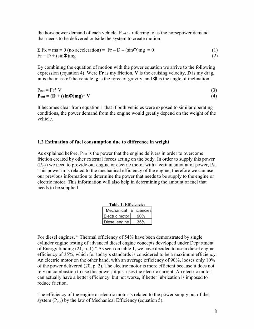
To determine the horsepower demand, of the engine or electric motor, the weight of each component mentioned above has to be considered. The main focus is on PEM (Proton Exchange Membrane) fuel cells. PEM fuel cells have been chosen because they are considered to be more suitable for vehicle applications, and their high efficiency when pure hydrogen is used. 2.1a Diesel engine truck characteristics A typical Class 8 Truck (Figure 9) weights about 12000 lb. For this truck design I have chosen a 500 hp diesel engine whose weight is 2867 lb (11, p. 1). With a fuel capacity of 100 gallons, the fuel tank, an aluminum cylinder, would weight about 560 lb (17, p.1). The transmission weight about 880 lb. Table 3 as well as figure 9 summarize these main components.
Table 3: Diesel engine truck components and specifications
Parts Specifications Engine 500hp, 2867lb Transmission 880lb Fuel Tank Gasoline, 100 gallons, 560lb
12
~880lb Engine Transmission ~2867lb Fuel ~560lb Tank
Figure 9: Diesel engine truck diagram 2.1b Fuel cell truck characteristics, pure hydrogen fuel
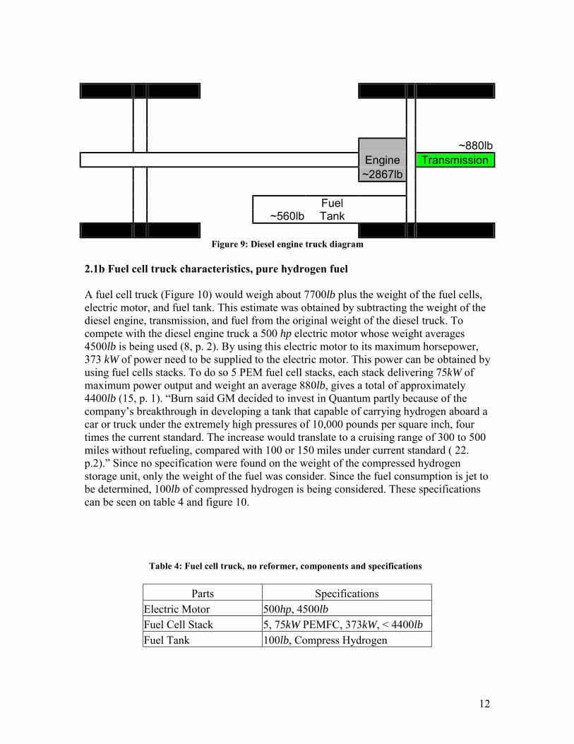
A fuel cell truck (Figure 10) would weigh about 7700lb plus the weight of the fuel cells, electric motor, and fuel tank. This estimate was obtained by subtracting the weight of the diesel engine, transmission, and fuel from the original weight of the diesel truck. To compete with the diesel engine truck a 500 hp electric motor whose weight averages 4500lb is being used (8, p. 2). By using this electric motor to its maximum horsepower, 373 kW of power need to be supplied to the electric motor. This power can be obtained by using fuel cells stacks. To do so 5 PEM fuel cell stacks, each stack delivering 75kW of maximum power output and weight an average 880lb, gives a total of approximately 4400lb (15, p. 1). “Burn said GM decided to invest in Quantum partly because of the company’s breakthrough in developing a tank that capable of carrying hydrogen aboard a car or truck under the extremely high pressures of 10,000 pounds per square inch, four times the current standard. The increase would translate to a cruising range of 300 to 500 miles without refueling, compared with 100 or 150 miles under current standard ( 22. p.2).” Since no specification were found on the weight of the compressed hydrogen storage unit, only the weight of the fuel was consider. Since the fuel consumption is jet to be determined, 100lb of compressed hydrogen is being considered. These specifications can be seen on table 4 and figure 10.
Table 4: Fuel cell truck, no reformer, components and specifications
Parts Specifications Electric Motor 500hp, 4500lb Fuel Cell Stack 5, 75kW PEMFC, 373kW, < 4400lb Fuel Tank 100lb, Compress Hydrogen

13
Fuel Tank ~100lb Electric Fuel Cell Motor ~4500lb ~4400lb
Figure 10: Fuel cell truck diagram, compressed hydrogen approach
2.1c Fuel cell truck characteristics, with reformer
If any other hydrogen rich fuel were considered as the choice of fuel, an onboard reformer would have to be added. As stated by the McDermott Technology, an onboard reformer would have an estimated weight of 440lb (17, p.4). In addition, the weight of the fuel would have to be considered. For simplicity, and because it can be more easily applied to the market, gasoline will be the fuel of choice.
Table 5: Fuel Cell Truck, With Reformer, components and specifications
Parts Specifications Electric Motor 500hp, 4500lb Fuel Cell Stack 5, 75kW PEMFC, 373kW, < 4400lb Fuel Tank Gasoline, 100 gallons, 560lb Reformer 440lb
Fuel Tank ~560lb Electric Fuel Cell Motor ~4500lb Reformer ~440lb ~4400lb
Figure 11: Fuel cell truck, with reformer

14
2.1d Comparison
Knowing an estimated weight of the crucial components allows for a comparison between the diesel truck and the fuel cell truck. Figure 12 concludes that the fuel cell truck is ~39% more massive that diesel truck, and that the Fuel cell truck with a reformer is ~46% more massive that diesel truck.
46%
1%26%
27%
26%
25%
43%
3% 3%
Figure 12: Weight comparison
24%
7%
5%64%
A: Diesel Truck (12000 lb) 24% Diesel Engine 7% Transmission 5% Fuel 64% Other parts
B: Fuel Cell Truck, No Reformer (16700 lb) 26% Fuel Cells 27% Electric Motor 1% Fuel, Compressed Hydrogen 46% Other Parts
C: Fuel Cell Truck With reformer (17600lb) 25% Fuel Cells 26% Electric Motor 3% Fuel Tank (gasoline) 3% Onboard Reformer 43% Other parts
15
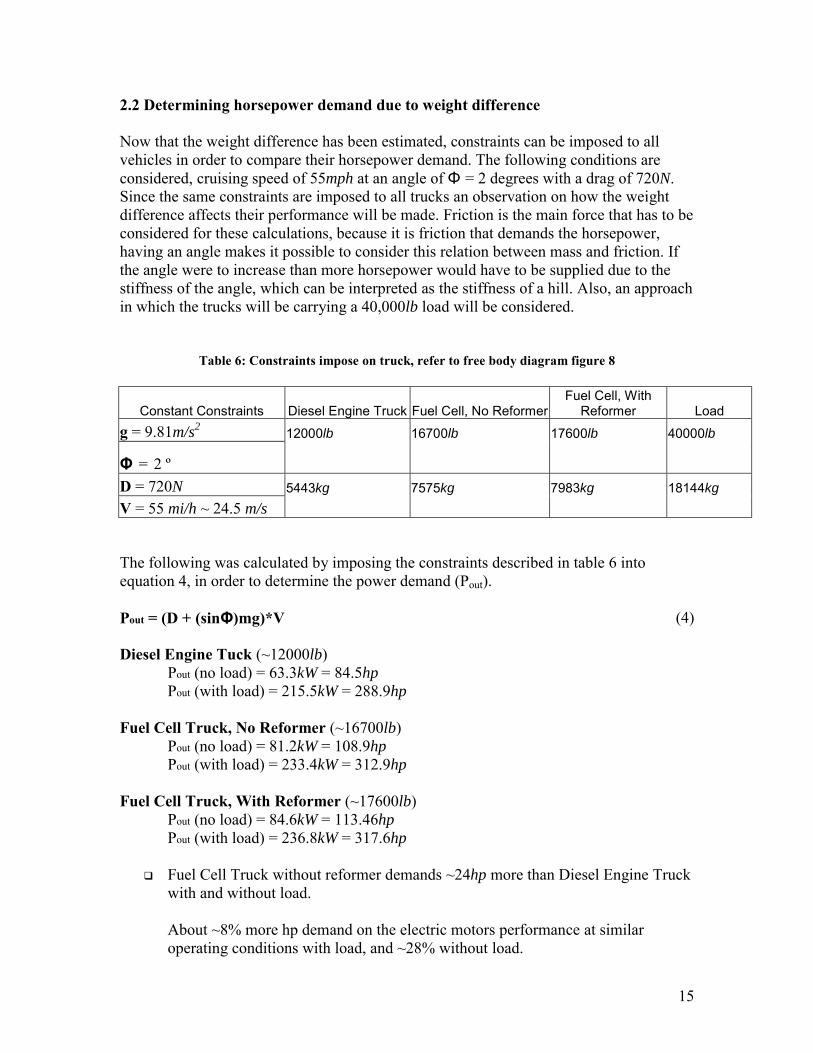
2.2 Determining horsepower demand due to weight difference Now that the weight difference has been estimated, constraints can be imposed to all vehicles in order to compare their horsepower demand. The following conditions are considered, cruising speed of 55mph at an angle of Φ = 2 degrees with a drag of 720N. Since the same constraints are imposed to all trucks an observation on how the weight difference affects their performance will be made. Friction is the main force that has to be considered for these calculations, because it is friction that demands the horsepower, having an angle makes it possible to consider this relation between mass and friction. If the angle were to increase than more horsepower would have to be supplied due to the stiffness of the angle, which can be interpreted as the stiffness of a hill. Also, an approach in which the trucks will be carrying a 40,000lb load will be considered.
Table 6: Constraints impose on truck, refer to free body diagram figure 8
Constant Constraints Diesel Engine Truck Fuel Cell, No Reformer Fuel Cell, With
Reformer
Load g = 9.81m/s2 12000lb 16700lb 17600lb 40000lb
Φ = 2 º D = 720N 5443kg 7575kg 7983kg 18144kg V = 55 mi/h ~ 24.5 m/s
The following was calculated by imposing the constraints described in table 6 into equation 4, in order to determine the power demand (Pout). Pout = (D + (sinΦ)mg)*V (4) Diesel Engine Tuck (~12000lb) Pout (no load) = 63.3kW = 84.5hp
Pout (with load) = 215.5kW = 288.9hp Fuel Cell Truck, No Reformer (~16700lb) Pout (no load) = 81.2kW = 108.9hp Pout (with load) = 233.4kW = 312.9hp Fuel Cell Truck, With Reformer (~17600lb) Pout (no load) = 84.6kW = 113.46hp Pout (with load) = 236.8kW = 317.6hp
#" Fuel Cell Truck without reformer demands ~24hp more than Diesel Engine Truck with and without load. About ~8% more hp demand on the electric motors performance at similar operating conditions with load, and ~28% without load.
16
#" Fuel Cell Truck with reformer demands ~29hp more than Diesel Engine Truck with and without load.
About ~10% more hp demand on the electric motors performance at similar operating conditions with load, and ~33% without load.
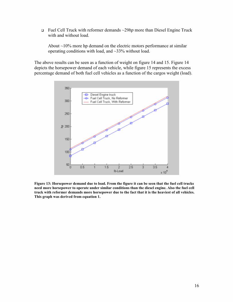
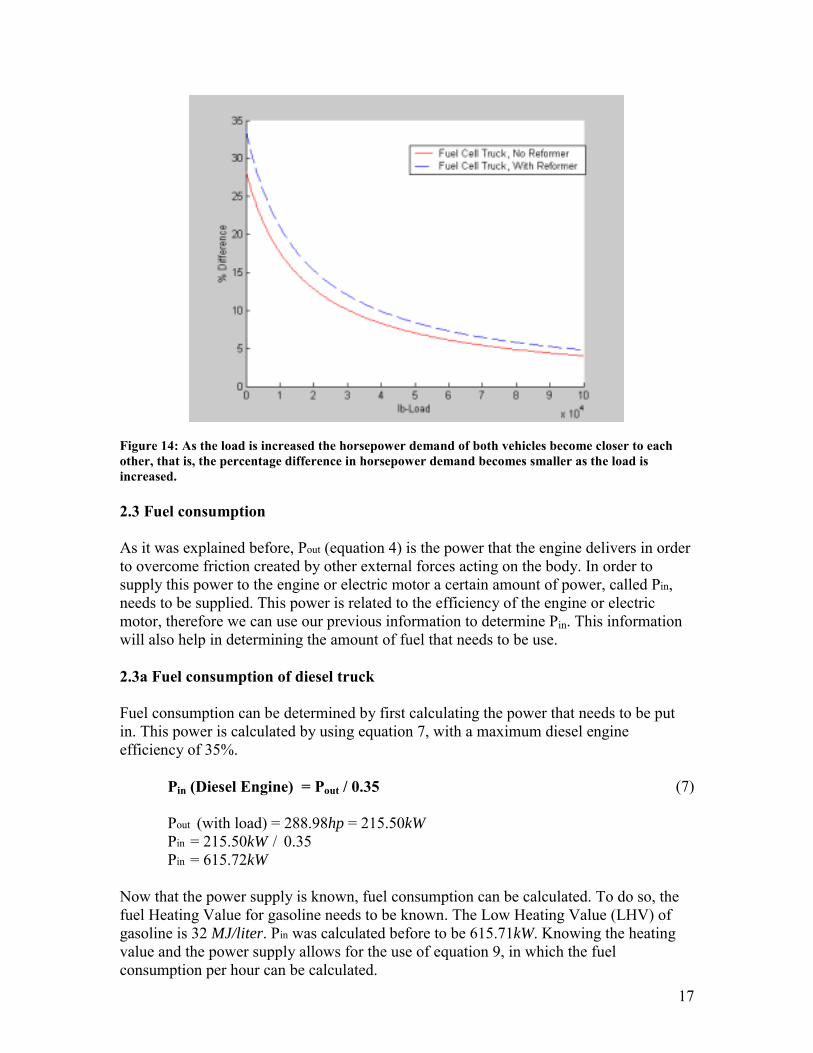
The above results can be seen as a function of weight on figure 14 and 15. Figure 14 depicts the horsepower demand of each vehicle, while figure 15 represents the excess percentage demand of both fuel cell vehicles as a function of the cargos weight (load).
Figure 13: Horsepower demand due to load. From the figure it can be seen that the fuel cell trucks need more horsepower to operate under similar conditions than the diesel engine. Also the fuel cell truck with reformer demands more horsepower due to the fact that it is the heaviest of all vehicles. This graph was derived from equation 1.
17
Figure 14: As the load is increased the horsepower demand of both vehicles become closer to each other, that is, the percentage difference in horsepower demand becomes smaller as the load is increased. 2.3 Fuel consumption As it was explained before, Pout (equation 4) is the power that the engine delivers in order to overcome friction created by other external forces acting on the body. In order to supply this power to the engine or electric motor a certain amount of power, called Pin, needs to be supplied. This power is related to the efficiency of the engine or electric motor, therefore we can use our previous information to determine Pin. This information will also help in determining the amount of fuel that needs to be use.
2.3a Fuel consumption of diesel truck Fuel consumption can be determined by first calculating the power that needs to be put in. This power is calculated by using equation 7, with a maximum diesel engine efficiency of 35%. Pin (Diesel Engine) = Pout / 0.35 (7)
Pout (with load) = 288.98hp = 215.50kW Pin = 215.50kW / 0.35
Pin = 615.72kW Now that the power supply is known, fuel consumption can be calculated. To do so, the fuel Heating Value for gasoline needs to be known. The Low Heating Value (LHV) of gasoline is 32 MJ/liter. Pin was calculated before to be 615.71kW. Knowing the heating value and the power supply allows for the use of equation 9, in which the fuel consumption per hour can be calculated.

18
[X gal / hr] * [LHV] = [Pin ] (9) [X] * [3.79 L / 1 gal] * [32 MJ / L] * [1 hr / 3600s] = [615.71 kJ / s] [X] * [33688.89 hr J / gal s] = [615.71 kJ / s]
X = 18.276 gal / hr Cruising at 55 mph, we arrived at the following fuel consumption… [hr/55m] * [18.275 gal/hr] = 0.33 gal / m
Figure 15: Fuel rate of consumption at 55mph speed vs. load, as expected fuel consumption increases
as the load is increased. Derived from equation 9
Table 7: Diesel engine truck, derived values
LHV 32 MJ / L Power demand (Pout) 250.50kW Power supply (Pin) 615.71 kW Speed 55 mph Load 40,000lb Fuel Tank 100 gallons, Gasoline Fuel consumption 0.33 gal / m
From the above calculation, it was determined that the12,000lb Diesel Engine Truck with a 40,000lb load and a cruising speed of 55 mph will consume an average of one third of a gallon per mile. This mean that it can go for up to 300mile without refueling.
19
2.3b Fuel consumption of fuel cell truck, Pure hydrogen approach
To calculate the fuel consumption for the fuel cell truck with no reformer, the power supplied (Pin) needs to be known. It was previously determined the horsepower demand to be 312.96hp for the 16,700lb fuel cell truck with a 40,000lb load. With an electric motor efficiency of 90%, equation 8 is used to find the power supply. Pin (Electric Motor) = Pout / 0.90 (8)
Pout (with load) = 312.96hp = 233.38kW Pin = 233.38kW / 0.90 Pin = 259.31kW
Now that the power supply is known, fuel consumption can be calculated. As it was with the diesel engine truck a 300m trip is also considered. The following thermodynamic calculations are as follow. From equation 11 it follows that the energy needed for the trip is 5091.927 MJ. [Pin kJ / s] * [trip m] * [ hr / Speed m] * [3600 s / hr] = Energy Needed J (11) [259.31 kJ / s] * [300 m] * [ hr / 55 m] * [3600 s / hr] = 5091.927 MJ
From equations 14 the amount of Hydrogen consumed by the fuel cell for the 300m trip at 55mph can be calculated to be. [HV] [Energy Needed J] = X g H2 (14) [1 g H2 / 119.95 kJ] [5091.927 MJ] = 42486.683 g H2 = 93.67lb H2 Since pure hydrogen is being used, a fuel cell would have a maximum efficiency of 80% (13, p. 1). This means that in order for the fuel cell to produce the 259.31kW of power needed it would have to consume 93.67lb/0.80 = 117.09 lb of H2.

20
Figure 16: Fuel rate of consumption of fuel cell with pure hydrogen approach, at 55mph speed vs.
load.
Table 8: Fuel cell truck, Compresses hydrogen, derived values
HV of H2 119.95 kJ/g Power demand (Pout) 233.38 kW Power supply (Pin) 259.31 kW Energy needed 5091.927 MJ Load 40,000 lb Fuel Tank 100 lb, Compress H2 Fuel consumption 117.09 lb H2 Speed 55 mph Distance Travel 300 miles
From the above calculation it can be said that the 16,700lb fuel cell truck with a 40,000lb load would consume approximately 117.09lb of hydrogen for a 300m trip at 55mph. It can be observed that from the calculation the fuel cell truck will consume 17 lb more hydrogen that what it was initially considered. No additional calculations are needed because 17 lb of extra weight to the fuel cell truck would no significantly affect the rate of hydrogen consumption. 2.3c Fuel consumption, Fuel cell truck with reformer Calculating the fuel consumption of a fuel cell vehicle with reformer requires additional information from the reformer. The power supplied (Pin) and the energy needed for the trip need to be known to calculate the fuel consumption. To do so equations 8 and 11 are used in the same way when determining fuel consumption for pure hydrogen approach. Pin (Electric Motor) = Pout / 0.90 (8)

21
Pout (with load) = 317.60hp = 236.80kW Pin = 236.80kW / 0.90 Pin = 263.11kW
[Pin kJ / s] * [trip m] * [ hr / Speed m] * [3600 s / hr] = Energy Needed J (11) [263.11 kJ / s] * [300 m] * [ hr / 55 m] * [3600 s / hr] = 5166.524 MJ
From equations 14 the amount of Hydrogen consumed by the fuel cell for the 300m trip can be calculated to be. [HV] [Energy Needed J] = X g H2 (14) [1 g H2 / 119.95 kJ] [5166.524 MJ] = 43072.314g H2 = 94.96lb H2 Since the fuel cell is assumed to have an efficiency of 80%, the fuel consumption for the fuel cell will be 118.70lb H2. Now that the amount of hydrogen gas that the reformer needs to produce is known, the amount of gasoline needed for the trip can be estimated. According to Michael A. Inbody, and James C. Hedstrom among others from the Energy and Process Engineering Group at Los Alamos National Laboratory, a synthetic gasoline reformer would produce 36% H2, 28% N2, 17% CO2, and 17% H2O (6, p. 2). This in turns means that the following information is needed in order to make use of equation 16.
Table 9: moles and specific heat capacity values needed for the 94.96lb of H2.
Product Percentage Mass Moles of product Cp (1800K) ΔT = 1502 K H2 36% 118.70lb ‘ 53.84kg 26707.94 moles 33.65 J/mole* K 1502 K N2 28% 92.32lb ‘ 41.88kg 1494.99 moles 35.64 J/mole* K 1502 K
CO2 17% 56.05lb ‘ 25.43kg 577.84 moles 59.93 J/mole* K 1502 K H2O 17% 56.05lb ‘ 25.43kg 1411.58 moles 49.92 J/mole* K 1502 K
With the above information and with a HV of gasoline of 32 MJ/ L = 47.687 MJ/ kg, and a Heat of Combustion of – 44 MJ/ kg, it can me determined from equation16 that.
X = [1349.88 MJ (H2) + 80.03 MJ (N2) + 52.01 MJ (CO2) + 105.84 MJ (H2O)] / [3.387 MJ/kg] X = 468.78 kg of Gasoline, with the density of gasoline of 2.7594 kg/gal. X = 169.88 Gallons of Gasoline
X = Σ { [Cp(T) * moles * ΔT] H2 + [Cp(T) * moles * ΔT] a …} / [HV + HC] (16)
22
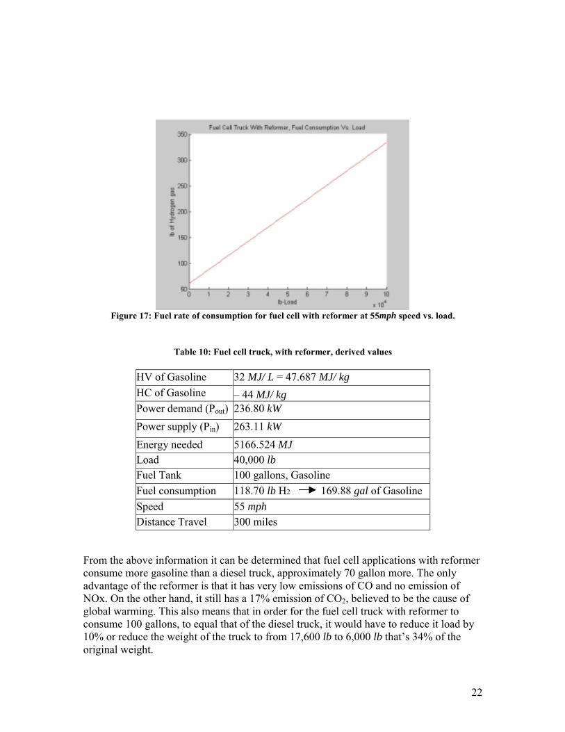
Figure 17: Fuel rate of consumption for fuel cell with reformer at 55mph speed vs. load.
Table 10: Fuel cell truck, with reformer, derived values
HV of Gasoline 32 MJ/ L = 47.687 MJ/ kg HC of Gasoline – 44 MJ/ kg Power demand (Pout) 236.80 kW Power supply (Pin) 263.11 kW Energy needed 5166.524 MJ Load 40,000 lb Fuel Tank 100 gallons, Gasoline Fuel consumption 118.70 lb H2 169.88 gal of Gasoline Speed 55 mph Distance Travel 300 miles
From the above information it can be determined that fuel cell applications with reformer consume more gasoline than a diesel truck, approximately 70 gallon more. The only advantage of the reformer is that it has very low emissions of CO and no emission of NOx. On the other hand, it still has a 17% emission of CO2, believed to be the cause of global warming. This also means that in order for the fuel cell truck with reformer to consume 100 gallons, to equal that of the diesel truck, it would have to reduce it load by 10% or reduce the weight of the truck to from 17,600 lb to 6,000 lb that’s 34% of the original weight.

23
3 Conclusion and Significance:
In theory, when comparing the power and fuel demand that a diesel engine truck has vs. two possible trucks with fuel cell applications the following observations were made. Table 11: Horsepower demand for a 300 mile trip at 55mph cruising speed, with a 40,000 lb load on
a hill with a 2 degree slope.
Trucks Weight lb More massive
that Diesel Truck Horsepower
demand Percentage hp demand
Diesel Engine 12000 288.9hp Fuel Cell With Pure Hydrogen 16700 39% 312.9hp 28% Fuel Cell With Reformer 17600 46% 317.6hp 33%
Fuel Cell Trucks were determined to be approximately 40% more massive than the Diesel Engine Truck (table 11). This difference in weight is mostly due to the fuel cell stacks and the electric motor. As we know, electric motors require big magnets to operate; this in turn makes them twice as massive as the diesel engine. Fuel cell stacks, on the other hand, become more massive as more electricity is needed. Fuel cell technology is constantly improving and companies are currently working to reduce their size and weight, which would definitely benefit the performance of class 8 fuel cell truck vehicles.
Table 12: The above values were derived from the following constraints, a 300 mile trip at 55mph cruising speed, with a 40,000 lb load on a hill with 2 degrees of inclination. The energy consumption
in Btu of Hydrogen was determined with a LHV of 51572. 5 Btu/lb at standard pressure and temperature, and the energy consumption of gasoline with a LHV of 115000 Btu/gal.
Trucks Fuel Consumption Energy Consumption
in MBtu Difference in
Energy Demand Diesel Engine 100 gallons of Gasoline 11.500 2 times that of H2 Fuel Cell With Reformer 169.88 gallons of Gasoline 19.536 3 times that of H2 Fuel Cell With Pure Hydrogen 117.09 lb of H2 6.038
0
5
10
15
20
1 2 3
Weight, K lb
Energy Requare, MBtu
Figure 18: Weight comparison in the thousands of pounds, and energy consumption in MBtu for a 300 mile trip at 55mph.
Diesel Engine Fuel Cell, Compressed Hydrogen
Fuel Cell, Reformer
24
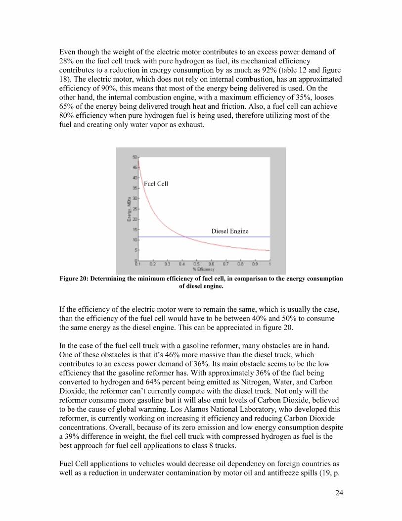
Even though the weight of the electric motor contributes to an excess power demand of 28% on the fuel cell truck with pure hydrogen as fuel, its mechanical efficiency contributes to a reduction in energy consumption by as much as 92% (table 12 and figure 18). The electric motor, which does not rely on internal combustion, has an approximated efficiency of 90%, this means that most of the energy being delivered is used. On the other hand, the internal combustion engine, with a maximum efficiency of 35%, looses 65% of the energy being delivered trough heat and friction. Also, a fuel cell can achieve 80% efficiency when pure hydrogen fuel is being used, therefore utilizing most of the fuel and creating only water vapor as exhaust.
Figure 20: Determining the minimum efficiency of fuel cell, in comparison to the energy consumption
of diesel engine.
If the efficiency of the electric motor were to remain the same, which is usually the case, than the efficiency of the fuel cell would have to be between 40% and 50% to consume the same energy as the diesel engine. This can be appreciated in figure 20. In the case of the fuel cell truck with a gasoline reformer, many obstacles are in hand. One of these obstacles is that it’s 46% more massive than the diesel truck, which contributes to an excess power demand of 36%. Its main obstacle seems to be the low efficiency that the gasoline reformer has. With approximately 36% of the fuel being converted to hydrogen and 64% percent being emitted as Nitrogen, Water, and Carbon Dioxide, the reformer can’t currently compete with the diesel truck. Not only will the reformer consume more gasoline but it will also emit levels of Carbon Dioxide, believed to be the cause of global warming. Los Alamos National Laboratory, who developed this reformer, is currently working on increasing it efficiency and reducing Carbon Dioxide concentrations. Overall, because of its zero emission and low energy consumption despite a 39% difference in weight, the fuel cell truck with compressed hydrogen as fuel is the best approach for fuel cell applications to class 8 trucks. Fuel Cell applications to vehicles would decrease oil dependency on foreign countries as well as a reduction in underwater contamination by motor oil and antifreeze spills (19, p.
Fuel Cell
Diesel Engine

25
1-2) Despite these and other environmental advantage that fuel cell applications have to offer, many obstacles prevent their vehicle applications to the market.
!"First, fuel cell applications to vehicles is a new concept to engineers, in other words more testing needs to be done to make sure that it is both safe for the environment and consumer.
!"Second, current fuel cells sell for about $3,000 to $5,000 per kW, preventing any vehicle with fuel cell applications to be introduced to the market because of its capital cost. If world mass production of fuel cells were achieved than their price would come down.
!"Third, even if fuel cell prices dropped there would still be no fuel distribution infrastructure of hydrogen gas to live up to the consumer demands.
It is important to have such infrastructure to accommodate and encourage drivers to pursue a hydrogen economy. Therefore, it is recommended that future research be made in determining both the cost of establishing a hydrogen infrastructure that servers the public in an efficient way, as well as determining the challenges that need to be overcome when it comes to transportation and distributing. Such problems need to be overcome first in order to have a safe and confident transition from the current gasoline infrastructure to a future hydrogen economy.

26
Reference:
1. Douglas C. Giancoli, Physics for scientists & Engineeres, 3rd Edition, Volume I, Prentice Hall, 2000
2. EG&G Services Parsons, Inc. Fuel Cell Handbook (Fifth Edition), Morgantown,
West Virginia, 2000
3. Frank Kreith, Dena Sue Potestio, and Chad Kimbell, Ground Transportation for the 21st Century, ASME, New York, 1999.
4. Jim Motavalli, Forward Drive, Sierra Club Books, San Francisco, 2000
5. Michael J. Morgan and Howard N. Shapiro, Fundamentals of Engineering
Thermodynamics (Fourth Edition), John Wiley and Sons, Inc. New York, 200 (pages 715 – 717, 847 table A-25).
6. Michael A Inbody, James C. Hedstrom, Jose I. Tafoya, Kenneth R. Stroh, and
Nicholas E. Vanderborgh, “Transient Carbon Monoxide Control for PEM Fuel Cell Sytems” , Energy and process Engineering Group. Los Alamos National Laboratory, Los Alamos New Mexico, 1998 Fuel Cell seminar
7. P.W. Atkins, Physical Chemistry (Second Edition), W.H. Freeman and Company,
San Francisco, 1982 (pages 105-109).
8. Baldor Motors and Drives, “AC motors manufacturer and specifications” http://www.baldor.com
9.
BIN, “Bioenergy Conversion Factors”. http://bioenergy.ornl.gov/papers/misc/energy_conv.html
10. Business 2.2 – magazine article- “A Wild Vision for Fuel-Cell Viecles”, By Atuart Brown, April 2002 Issue. http://www.business2.com/articles/mag/0,1640,39589,FF.html
11. Caterpillar, Heavy Duty Equipment, “Diesel Engines“ http://www.cat.com 12. 13
Ford Company, Fuel Cell Cars, “How Internal Combustion Engine Works?” http://www.howstuffworks.com/news-item10.htm Ford Company, Fuel Cell Cars, “How Fuel Cell Works?” http://www.howstuffworks.com/fuel-cell4.htm
14. Fuel Cells 2000, “How Fuel Cells Work?” http://www.fuelcells.org/ 15. Isecorp, “Fuel Cell applications to commercial buses”.
http://www.isecorp.com/spec_30_foot_FCV.htm
27
16. Schatz Energy Research Center, “How a Fuel Cell Works:” http://www.humboldt.edu/~serc/index.shtml
17.
18.
19.
20.
21.
22.
Sterling Company, “Heavy Duty Truck Specifications” http://www.sterlingtrucks.com McDermott Technology Inc., “Compact Fuel Processor for Fuel Cell-Powered Vehicles”, Fuel Cell Technology Review Conference, August 3-5 1999. Monroe County Solid Water Management District, “Motor Oil and the Environment”, South Bloomington, IN. Bangor Hydro Electric Company, “The Future of Electrics”. http://www.bhe.com/about/future_elec.cfm Thermal Barrier Coatings For Low Emission, High Efficiency Diesel Engine Applications. M. B. Beardsley, P. G. Happoldt and K. C. Kelley, Caterpillar Inc. E. F. Rejda and D. F. Socie University of Illinois. April 26-28 1999 MSNBC, GM Article, “GM says its future is in fuel cells” http://www.msnbc.com/news/586532.asp