Embed Size (px)
Citation preview

www.SpecialtyFlange.comCopyright © 2006 Specialty Flange & Fitting, Inc. All Rights Reserved. • Phone: (856) 728-8530 • Fax: (856) 728-1304
649 Lebanon Avenue, Williamstown, NJ, 08094 • Email: [email protected]
Wholesaler of Carbon, Stain less, and Special ty A l loyPipe, Valve, & Fi t t ing Products for Over 25 Years
F L A N G EP R O D U C TC A T A L O G
SLIP-ON
THREADEDWELD NECK
LAP JOINT
SOCKET WELD
B
BLIND
ORIFICE UNIONS WITH PLATES

1. The C and Y dimensions include the 1/16” raised face for the 150# and 300# weight classes.2. Tolerances are standard as per ANSI B 16.5
3. The Y3 dimension is the length for a “true” lap joint, however, it isusually accepted to make these to a standard slip-on length.4. All shown dimensions are in inches. 5. Bolts 1/8” smaller than hole dia.
X
B
R
O
C Y
1/16”Raised
Face
SLIP-ON (SO)
R
O
C Y
1/16”Raised
Face
THREADED (TH)
X
B2
H
R
O
CY2
1/16”Raised
Face
WELD NECK (WN)
X
X
B3
O
C Y3
LAP JOINT (L J)
f r
B2
XB
R
O
C Y
1/16”Raised
Face
SOCKET WELD (SW)
D
B
R
O
C
1/16”Raised
Face
BLIND (BL)
Nominal Pipe Size
O(Outside Diam-eter)
R(Raised Face)
X(HubDia.)
C(General
Thick-ness)
Y(OverallLength)
Y2 Y3 B(Inside Diam-eter)
B2 B3 fr(fillet
radius)
D H(Dia. bevel hub)
# of Holes -
Diameter
Bolt Circle Dia.
1/2” 3.50 1.38 1.19 0.44 0.62 1.88 0.62 0.88 0.90 0.12 0.38 0.84 4 - 0.62 2.38
3/4” 3.88 1.69 1.50 0.50 0.62 2.06 0.62 1.09 1.11 0.12 0.44 1.05 4 - 0.62 2.75
1” 4.25 2.00 1.94 0.56 0.69 2.19 0.69 1.36 1.38 0.12 0.50 1.32 4 - 0.62 3.12
1-1/4” 4.62 2.50 2.31 0.62 0.81 2.25 0.81 1.70 1.72 0.19 0.56 1.66 4 - 0.62 3.50
1-1/2” 5.00 2.88 2.56 0.68 0.88 2.44 0.88 1.95 1.97 0.25 0.62 1.90 4 - 0.62 3.88
2” 6.00 3.62 3.06 0.75 1.00 2.50 1.00 2.44 2.46 0.31 0.69 2.38 4 - 0.75 4.75
2-1/2” 7.00 4.12 3.56 0.88 1.12 2.75 1.12 2.94 2.97 0.31 0.75 2.88 4 - 0.75 5.50
3” 7.50 5.00 4.25 0.94 1.19 2.75 1.19 3.57 3.60 0.38 0.81 3.50 4 - 0.75 6.00
3-1/2” 8.50 5.50 4.81 0.94 1.25 2.81 1.25 4.07 4.10 0.38 0.88 4.00 8 - 0.75 7.00
4” 9.00 6.19 5.31 0.94 1.31 3.00 1.31 4.57 4.60 0.44 0.94 4.50 8 - 0.75 7.50
5” 10.00 7.31 6.44 0.94 1.44 3.50 1.44 5.66 5.69 0.44 0.94 5.56 8 - 0.88 8.50
6” 11.00 8.50 7.56 1.00 1.56 3.50 1.56 6.72 6.75 0.50 1.06 6.63 8 - 0.88 9.50
8” 13.50 10.62 9.69 1.12 1.75 4.00 1.75 8.72 8.75 0.50 1.25 8.63 8 - 0.88 11.75
10” 16.00 12.75 12.00 1.19 1.94 4.00 1.94 10.88 10.92 0.50 1.31 10.75 12 - 1.00 14.25
12” 19.00 15.00 14.38 1.25 2.19 4.50 2.19 12.88 12.92 0.50 1.56 12.75 12 - 1.00 17.00
14” 21.00 16.25 15.75 1.38 2.25 5.00 3.12 14.14 14.18 0.50 1.63 14.00 12 - 1.12 18.75
16” 23.50 18.50 18.00 1.44 2.50 5.00 3.44 16.16 16.19 0.50 1.75 16.00 16 - 1.12 21.25
18” 25.00 21.00 19.88 1.56 2.69 5.50 3.81 18.18 18.20 0.50 1.94 18.00 16 - 1.25 22.75
20” 27.50 23.00 22.00 1.69 2.88 5.69 4.06 20.20 20.25 0.50 2.13 20.00 20 - 1.25 25.00
22” 29.50 25.25 24.25 1.81 3.13 5.88 4.25 22.22 22.25 0.50 2.38 22.00 20 - 1.38 27.25
24” 32.00 27.25 26.12 1.88 3.25 6.00 4.38 24.25 24.25 0.50 2.50 24.00 20 - 1.38 29.50
CLASS 150#ANSI B16.5 • Standard Forged Flanges
Dimensional Data
This dim
ensio
n is de
term
ined
by the
pip
e
sche
dule
and
its co
rresp
ond
ing insid
e d
iam
ete
r.
Copyr ight © 2006 Special ty F lange & Fi t t ing, Inc. A l l R ights Reser ved. • Phone: (856) 728-8530 • Fax: (856) 728-1304649 Lebanon Avenue, Wi l l iamstown, NJ, 08094 • Emai l :sales@Special tyF lange.com • Web S i te:Special tyF lange.com
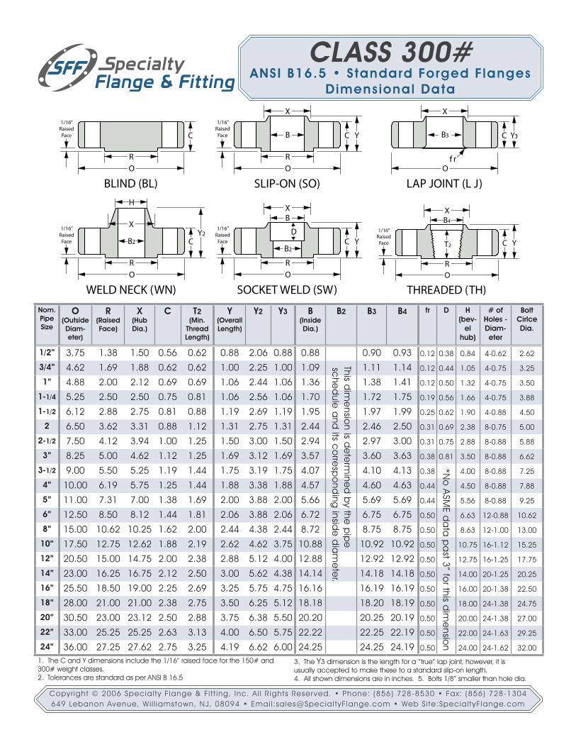
1. The C and Y dimensions include the 1/16” raised face for the 150# and 300# weight classes.2. Tolerances are standard as per ANSI B 16.5
3. The Y3 dimension is the length for a “true” lap joint, however, it isusually accepted to make these to a standard slip-on length.4. All shown dimensions are in inches. 5. Bolts 1/8” smaller than hole dia.
Nom.Pipe Size
O(Outside Diam-eter)
R(Raised Face)
X(HubDia.)
C T2(Min.
ThreadLength)
Y(OverallLength)
Y2 Y3 B(Inside Dia.)
B2 B3 B4 fr D H (bev-
el hub)
# of Holes - Diam-eter
Bolt Cirlce Dia.
1/2” 3.75 1.38 1.50 0.56 0.62 0.88 2.06 0.88 0.88 0.90 0.93 0.12 0.38 0.84 4-0.62 2.62
3/4” 4.62 1.69 1.88 0.62 0.62 1.00 2.25 1.00 1.09 1.11 1.14 0.12 0.44 1.05 4-0.75 3.25
1” 4.88 2.00 2.12 0.69 0.69 1.06 2.44 1.06 1.36 1.38 1.41 0.12 0.50 1.32 4-0.75 3.50
1-1/4 5.25 2.50 2.50 0.75 0.81 1.06 2.56 1.06 1.70 1.72 1.75 0.19 0.56 1.66 4-0.75 3.88
1-1/2 6.12 2.88 2.75 0.81 0.88 1.19 2.69 1.19 1.95 1.97 1.99 0.25 0.62 1.90 4-0.88 4.50
2 6.50 3.62 3.31 0.88 1.12 1.31 2.75 1.31 2.44 2.46 2.50 0.31 0.69 2.38 8-0.75 5.00
2-1/2 7.50 4.12 3.94 1.00 1.25 1.50 3.00 1.50 2.94 2.97 3.00 0.31 0.75 2.88 8-0.88 5.88
3” 8.25 5.00 4.62 1.12 1.25 1.69 3.12 1.69 3.57 3.60 3.63 0.38 0.81 3.50 8-0.88 6.62
3-1/2 9.00 5.50 5.25 1.19 1.44 1.75 3.19 1.75 4.07 4.10 4.13 0.38 4.00 8-0.88 7.25
4” 10.00 6.19 5.75 1.25 1.44 1.88 3.38 1.88 4.57 4.60 4.63 0.44 4.50 8-0.88 7.88
5” 11.00 7.31 7.00 1.38 1.69 2.00 3.88 2.00 5.66 5.69 5.69 0.44 5.56 8-0.88 9.25
6” 12.50 8.50 8.12 1.44 1.81 2.06 3.88 2.06 6.72 6.75 6.75 0.50 6.63 12-0.88 10.62
8” 15.00 10.62 10.25 1.62 2.00 2.44 4.38 2.44 8.72 8.75 8.75 0.50 8.63 12-1.00 13.00
10” 17.50 12.75 12.62 1.88 2.19 2.62 4.62 3.75 10.88 10.92 10.92 0.50 10.75 16-1.12 15.25
12” 20.50 15.00 14.75 2.00 2.38 2.88 5.12 4.00 12.88 12.92 12.92 0.50 12.75 16-1.25 17.75
14” 23.00 16.25 16.75 2.12 2.50 3.00 5.62 4.38 14.14 14.18 14.18 0.50 14.00 20-1.25 20.25
16” 25.50 18.50 19.00 2.25 2.69 3.25 5.75 4.75 16.16 16.19 16.19 0.50 16.00 20-1.38 22.50
18” 28.00 21.00 21.00 2.38 2.75 3.50 6.25 5.12 18.18 18.20 18.19 0.50 18.00 24-1.38 24.75
20” 30.50 23.00 23.12 2.50 2.88 3.75 6.38 5.50 20.20 20.25 20.19 0.50 20.00 24-1.38 27.00
22” 33.00 25.25 25.25 2.63 3.13 4.00 6.50 5.75 22.22 22.25 22.19 0.50 22.00 24-1.63 29.25
24” 36.00 27.25 27.62 2.75 3.25 4.19 6.62 6.00 24.25 24.25 24.19 0.50 24.00 24-1.62 32.00
X
B
R
O
C Y
1/16”Raised
Face
SLIP-ON (SO)
B2
H
R
O
CY2
1/16”Raised
Face
WELD NECK (WN)
X
X
B3
O
C Y3
LAP JOINT (L J)
f r
B2
XB
R
O
C Y
1/16”Raised
Face
SOCKET WELD (SW)
D
B
R
O
C
1/16”Raised
Face
BLIND (BL)
R
O
C Y
1/16”Raised
Face
THREADED (TH)
T2
XB4
This dim
ensio
n is de
term
ined
by the
pip
e
sche
dule
and
its co
rresp
ond
ing insid
e d
iam
ete
r.
*No
ASM
E da
ta p
ast 3” fo
r this dim
ensio
n
CLASS 300#ANSI B16.5 • Standard Forged Flanges
Dimensional Data
Copyr ight © 2006 Special ty F lange & Fi t t ing, Inc. A l l R ights Reser ved. • Phone: (856) 728-8530 • Fax: (856) 728-1304649 Lebanon Avenue, Wi l l iamstown, NJ, 08094 • Emai l :sales@Special tyF lange.com • Web S i te:Special tyF lange.com

Nom.Pipe Size
O(Outside Diam-eter)
R(Raised Face)
X(HubDia.)
C T2(Min.
ThreadLength)
Y(OverallLength)
Y2 Y3 B(Inside Dia.)
B2 B3 B4 fr D H (bev-
el hub)
# of Holes - Diam-eter
Bolt Cirlce Dia.
1/2” 3.75 1.38 1.50 0.56 0.62 0.88 2.06 0.88 0.88 0.90 0.93 0.12 0.38 0.84 4-0.62 2.62
3/4” 4.62 1.69 1.88 0.62 0.62 1.00 2.25 1.00 1.09 1.11 1.14 0.12 0.44 1.05 4-0.75 3.25
1” 4.88 2.00 2.12 0.69 0.69 1.06 2.44 1.06 1.36 1.38 1.41 0.12 0.50 1.32 4-0.75 3.50
1-1/4 5.25 2.50 2.50 0.81 0.81 1.12 2.62 1.12 1.70 1.72 1.75 0.19 0.56 1.66 4-0.75 3.88
1-1/2 6.12 2.88 2.75 0.88 0.88 1.25 2.75 1.25 1.95 1.97 1.99 0.25 0.62 1.90 4-0.88 4.50
2 6.50 3.62 3.31 1.00 1.12 1.44 2.88 1.44 2.44 2.46 2.50 0.31 0.69 2.38 8-0.75 5.00
2-1/2 7.50 4.12 3.94 1.12 1.25 1.62 3.12 1.62 2.94 2.97 3.00 0.31 0.75 2.88 8-0.88 5.88
3” 8.25 5.00 4.62 1.25 1.38 1.81 3.25 1.81 3.57 3.60 3.63 0.38 0.81 3.50 8-0.88 6.62
3-1/2 9.00 5.50 5.25 1.38 1.56 1.94 3.38 1.94 4.07 4.10 4.13 0.38 4.00 8-1.00 7.25
4” 10.75 6.19 6.00 1.50 1.62 2.12 4.00 2.12 4.57 4.60 4.63 0.44 4.50 8-1.00 8.50
5” 13.00 7.31 7.44 1.75 1.88 2.38 4.50 2.38 5.66 5.69 5.69 0.44 5.56 8-1.12 10.50
6” 14.00 8.50 8.75 1.88 2.00 2.62 4.62 2.62 6.72 6.75 6.75 0.50 6.63 12-1.12 11.50
8” 16.50 10.62 10.75 2.19 2.25 3.00 5.25 3.00 8.72 8.75 8.75 0.50 8.63 12-1.25 13.75
10” 20.00 12.75 13.50 2.50 2.56 3.38 6.00 4.38 10.88 10.92 10.88 0.50 10.75 16-1.38 17.00
12” 22.00 15.00 15.75 2.62 2.75 3.62 6.12 4.62 12.88 12.92 12.94 0.50 12.75 20-1.38 19.25
14” 23.75 16.25 17.00 2.75 2.88 3.69 6.50 5.00 14.14 14.18 14.19 0.50 14.00 20-1.50 20.75
16” 27.00 18.50 19.50 3.00 3.06 4.19 7.00 5.50 16.16 16.19 18.19 0.50 16.00 20-1.62 23.75
18” 29.25 21.00 21.50 3.25 3.12 4.62 7.25 6.00 18.18 18.20 18.10 0.50 18.00 20-1.75 25.75
20” 32.00 23.00 24.00 3.50 3.25 5.00 7.50 6.50 20.20 20.25 20.19 0.50 20.00 24-1.75 28.50
22” 34.25 25.25 26.25 3.75 --- 5.25 7.75 6.88 22.22 22.25 --- 0.50 22.00 24-1.75 30.63
24” 37.00 27.25 28.25 4.00 3.62 5.50 8.00 7.25 24.25 24.25 24.19 0.50 24.00 24-2.00 33.00
This dim
ensio
n is de
term
ined
by the
pip
e
sche
dule
and
its co
rresp
ond
ing insid
e d
iam
ete
r.
*No
ASM
E da
ta p
ast 3” fo
r this dim
ensio
n
1. The C and Y dimensions do not include the 1/4” raised face for the 600# and above weight classes.2. Tolerances are standard as per ANSI B 16.5
3. The Y3 dimension is the length for a “true” lap joint, however, it isusually accepted to make these to a standard slip-on length.4. All shown dimensions are in inches. 5. Bolts 1/8” smaller than hole dia.
B2
XB
R
O
1/4”Raised
Face
SOCKET WELD (SW)
DC YB2
H
R
O
Y21/4”
RaisedFace
WELD NECK (WN)
C
X
X
B
R
O
C Y
1/4”Raised
Face
SLIP-ON (SO)
B
R
O
1/4”Raised
Face
BLIND (BL)
C
X
B3
O
C Y3
LAP JOINT (L J)
f r
R
O
1/4”Raised
Face
THREADED (TH)
C YT2
XB4
CLASS 600#ANSI B16.5 • Standard Forged Flanges
Dimensional Data
Copyr ight © 2006 Special ty F lange & Fi t t ing, Inc. A l l R ights Reser ved. • Phone: (856) 728-8530 • Fax: (856) 728-1304649 Lebanon Avenue, Wi l l iamstown, NJ, 08094 • Emai l :sales@Special tyF lange.com • Web S i te:Special tyF lange.com
*No
ASM
E da
ta p
ast 3” fo
r this dim
ensio
n
Nom.Pipe Size
O(Outside Diam-eter)
R(Raised Face)
X(HubDia.)
C T2(Min.
ThreadLength)
Y(OverallLength)
Y2 Y3 B(Inside Dia.)
B2 B3 B4 fr D H (bev-
el hub)
# of Holes - Diam-eter
Bolt Cirlce Dia.
1/2” 4.75 1.38 1.50 0.88 0.88 1.25 2.38 1.25 0.88 0.90 0.93 0.13 0.38 0.84 4-0.88 3.25
3/4” 5.13 1.69 1.75 1.00 1.00 1.38 2.75 1.38 1.09 1.11 1.14 0.13 0.44 1.05 4-0.88 3.50
1” 5.88 2.00 2.06 1.13 1.13 1.63 2.88 1.63 1.36 1.38 1.41 0.13 0.50 1.32 4-1.00 4.00
1-1/4 6.25 2.50 2.50 1.13 1.19 1.63 2.88 1.63 1.70 1.72 1.75 0.19 0.56 1.66 4-1.00 4.38
1-1/2 7.00 2.88 2.75 1.25 1.25 1.75 3.25 1.75 1.95 1.97 1.99 0.25 0.63 1.90 4-1.13 4.88
2 8.50 3.62 4.13 1.50 1.50 2.25 4.00 2.25 2.44 2.46 2.50 0.31 0.69 2.38 8-1.00 6.50
2-1/2 9.63 4.12 4.88 1.63 1.88 2.50 4.13 2.50 2.94 2.97 3.00 0.31 0.75 2.88 8-1.13 7.50
3” 9.50 5.00 5.00 1.50 1.63 2.13 4.00 2.13 3.57 3.60 3.63 0.38 * 3.50 8-1.00 7.50
4” 11.50 6.19 6.25 1.75 1.88 2.75 4.50 2.75 4.57 4.60 4.63 0.44 * 4.50 8-1.25 9.25
5” 13.75 7.31 7.50 2.00 2.13 3.13 5.00 3.13 5.66 5.69 5.69 0.44 * 5.56 8-1.38 11.00
6” 15.00 8.50 9.25 2.19 2.25 3.38 5.50 3.38 6.72 6.75 6.75 0.50 * 6.63 12-1.25 12.50
8” 18.50 10.62 11.75 2.50 2.50 4.00 6.38 4.50 8.72 8.75 8.75 0.50 * 8.63 12-1.50 15.50
10” 21.50 12.75 14.50 2.75 2.81 4.25 7.25 5.00 10.88 10.92 10.92 0.50 * 10.75 16-1.50 18.50
12” 24.00 15.00 16.50 3.13 3.00 4.63 7.88 5.63 12.88 12.92 12.92 0.50 * 12.75 20-1.50 21.00
14” 25.25 16.25 17.75 3.38 3.25 5.13 8.38 6.13 * 14.18 14.18 0.50 * 14.00 20-1.63 22.00
16” 27.75 18.50 20.00 3.50 3.38 5.25 8.50 6.50 * 16.19 16.19 0.50 * 16.00 20-1.75 24.25
18” 31.00 21.00 22.25 4.00 3.50 6.00 9.00 7.50 * 18.20 18.19 0.50 * 18.00 20-2.00 27.00
20” 33.75 23.00 24.50 4.25 3.63 6.25 9.75 8.25 * 20.25 20.19 0.50 * 20.00 20-2.13 29.50
24” 41.00 27.25 29.50 5.50 4.00 8.00 11.50 10.50 * 24.25 24.19 0.50 * 24.00 20-2.63 33.50
B2
XB
R
O
1/4”Raised
Face
SOCKET WELD (SW)
DC YB2
H
R
O
Y21/4”
RaisedFace
WELD NECK (WN)
C
X
X
B
R
O
C Y
1/4”Raised
Face
SLIP-ON (SO)
B
R
O
1/4”Raised
Face
BLIND (BL)
C
X
B3
O
C Y3
LAP JOINT (L J)
f r
R
O
1/4”Raised
Face
THREADED (TH)
C YT2
XB4
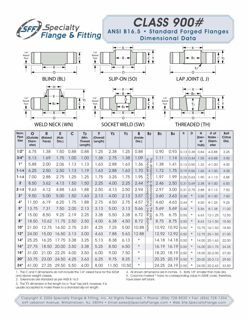
1. The C and Y dimensions do not include the 1/4” raised face for the 600# and above weight classes.2. Tolerances are standard as per ANSI B 16.53. The Y3 dimension is the length for a “true” lap joint, however, it isusually accepted to make these to a standard slip-on length.
4. All shown dimensions are in inches. 5. Bolts 1/8” smaller than hole dia.5. Columns marked * have no corresponding value in ASME code, therefore, have been left blank.
This dim
ensio
n is de
term
ined
by the
pip
e sc
hed
ule a
nd its c
orre
spo
nding
inside
dia
me
ter.
CLASS 900#ANSI B16.5 • Standard Forged Flanges
Dimensional Data
Copyr ight © 2006 Special ty F lange & Fi t t ing, Inc. A l l R ights Reser ved. • Phone: (856) 728-8530 • Fax: (856) 728-1304649 Lebanon Avenue, Wi l l iamstown, NJ, 08094 • Emai l :sales@Special tyF lange.com • Web S i te:Special tyF lange.com
Nom.Pipe Size
O(Outside Diam-eter)
R(Raised Face)
X(HubDia.)
C T2(Min.
ThreadLength)
Y(OverallLength)
Y2 Y3 B(Inside Dia.)
B2 B3 B4 fr D H (bev-
el hub)
# of Holes - Diam-eter
Bolt Cirlce Dia.
1/2” 4.75 1.38 1.50 0.88 0.88 1.25 2.38 1.25 0.88 0.90 0.93 0.13 0.38 0.84 4-0.88 3.25
3/4” 5.13 1.69 1.75 1.00 1.00 1.38 2.75 1.38 1.09 1.11 1.14 0.13 0.44 1.05 4-0.88 3.50
1” 5.88 2.00 2.06 1.13 1.13 1.63 2.88 1.63 1.36 1.38 1.41 0.13 0.50 1.32 4-1.00 4.00
1-1/4 6.25 2.50 2.50 1.13 1.19 1.63 2.88 1.63 1.70 1.72 1.75 0.19 0.56 1.66 4-1.00 4.38
1-1/2 7.00 2.88 2.75 1.25 1.25 1.75 3.25 1.75 1.95 1.97 1.99 0.25 0.63 1.90 4-1.13 4.88
2 8.50 3.62 4.13 1.50 1.50 2.25 4.00 2.25 2.44 2.46 2.50 0.31 0.69 2.38 8-1.00 6.50
2-1/2 9.63 4.12 4.88 1.63 1.88 2.50 4.13 2.50 2.94 2.97 3.00 0.31 0.75 2.88 8-1.13 7.50
3” 10.50 5.00 5.25 1.88 2.00 2.88 4.63 2.88 3.57 3.60 3.63 0.38 * 3.50 8-1.25 8.00
4” 12.25 6.19 6.38 2.13 2.25 3.56 4.88 3.56 4.57 4.60 4.63 0.44 * 4.50 8-1.38 9.50
5” 14.75 7.31 7.75 2.88 2.50 4.13 6.13 4.13 5.66 5.69 5.69 0.44 * 5.56 8-1.63 11.50
6” 15.50 8.50 9.00 3.25 2.75 4.69 6.75 4.69 6.72 6.75 6.75 0.50 * 6.63 12-1.50 12.50
8” 19.00 10.62 11.50 3.63 3.00 5.63 8.38 5.63 8.72 8.75 8.75 0.50 * 8.63 12-1.75 15.50
10” 23.00 12.75 14.50 4.25 3.31 6.25 10.00 7.00 10.88 10.92 10.92 0.50 * 10.75 12-2.00 19.00
12” 26.50 15.00 17.75 4.88 3.63 7.13 11.13 8.63 12.88 12.92 12.92 0.50 * 12.75 16-2.13 22.50
14” 29.50 16.25 19.50 5.25 * * 11.75 9.50 * 14.18 14.18 0.50 * 14.00 16-2.38 25.00
16” 32.50 18.50 21.75 5.75 * * 12.25 10.25 * 16.19 16.19 0.50 * 16.00 16-2.63 27.75
18” 36.00 21.00 23.50 6.38 * * 12.88 10.88 * 18.20 18.19 0.50 * 18.00 16-2.88 30.50
20” 38.75 23.00 25.25 7.00 * * 14.00 11.50 * 20.25 20.19 0.50 * 20.00 16-3.13 32.75
24” 46.00 27.25 30.00 8.00 * * 16.00 13.00 * 24.25 24.19 0.50 * 24.00 16-3.63 39.00
This dim
ensio
n is de
term
ined
by the
pip
e sc
hed
ule a
nd its c
orre
spo
nding
inside
dia
me
ter.
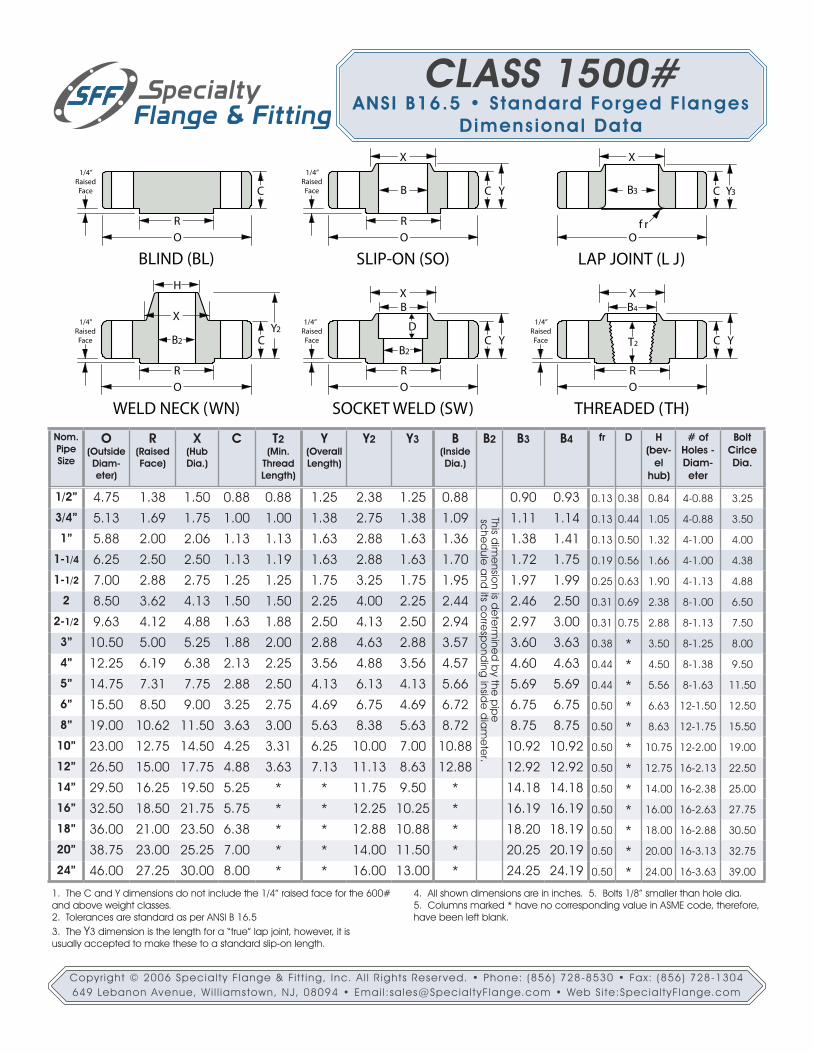
1. The C and Y dimensions do not include the 1/4” raised face for the 600# and above weight classes.2. Tolerances are standard as per ANSI B 16.53. The Y3 dimension is the length for a “true” lap joint, however, it isusually accepted to make these to a standard slip-on length.
4. All shown dimensions are in inches. 5. Bolts 1/8” smaller than hole dia.5. Columns marked * have no corresponding value in ASME code, therefore, have been left blank.
B2
XB
R
O
1/4”Raised
Face
SOCKET WELD (SW)
DC YB2
H
R
O
Y21/4”
RaisedFace
WELD NECK (WN)
C
X
X
B
R
O
C Y
1/4”Raised
Face
SLIP-ON (SO)
B
R
O
1/4”Raised
Face
BLIND (BL)
C
X
B3
O
C Y3
LAP JOINT (L J)
f r
R
O
1/4”Raised
Face
THREADED (TH)
C YT2
XB4
CLASS 1500#ANSI B16.5 • Standard Forged Flanges
Dimensional Data
Copyr ight © 2006 Special ty F lange & Fi t t ing, Inc. A l l R ights Reser ved. • Phone: (856) 728-8530 • Fax: (856) 728-1304649 Lebanon Avenue, Wi l l iamstown, NJ, 08094 • Emai l :sales@Special tyF lange.com • Web S i te:Special tyF lange.com

Nom.Pipe Size
O(Outside Diam-eter)
R(Raised Face)
X(HubDia.)
C T2(Min.
ThreadLength)
Y(OverallLength)
Y2 Y3 B(Inside Dia.)
B2 B3 B4 fr D H (bev-
el hub)
# of Holes - Diam-eter
Bolt Cirlce Dia.
1/2” 5.25 1.38 1.69 1.19 1.13 1.56 2.88 1.56 0.88 0.90 0.93 0.13 0.38 0.84 4-0.88 3.50
3/4” 5.50 1.69 2.00 1.25 1.25 1.69 3.13 1.69 1.09 1.11 1.14 0.13 0.44 1.05 4-0.88 3.75
1” 6.25 2.00 2.25 1.38 1.38 1.88 3.50 1.88 1.36 1.38 1.41 0.13 0.50 1.32 4-1.00 4.25
1-1/4 7.25 2.50 2.88 1.50 1.50 2.06 3.75 2.06 1.70 1.72 1.75 0.18 0.56 1.66 4-1.13 5.13
1-1/2 8.00 2.88 3.13 1.75 1.75 2.38 4.38 2.38 1.95 1.97 1.99 0.25 0.63 1.90 4-1.25 5.75
2 9.25 3.62 3.75 2.00 2.00 2.75 5.00 2.75 2.44 2.46 2.50 0.31 0.69 2.38 8-1.13 6.75
2-1/2 10.50 4.12 4.50 2.25 2.25 3.13 5.63 3.13 2.94 2.97 3.00 0.31 0.75 2.88 8-1.25 7.75
3” 12.00 5.00 5.25 2.63 2.50 3.63 6.63 3.63 3.57 3.60 3.63 0.37 * 3.50 8-1.38 9.00
4” 14.00 6.19 6.50 3.00 2.75 4.25 7.50 4.25 4.57 4.60 4.63 0.44 * 4.50 8-1.63 10.75
5” 16.50 7.31 8.00 3.63 3.00 5.13 9.00 5.13 5.66 5.69 5.69 0.44 * 5.56 8-1.88 12.75
6” 19.00 8.50 9.25 4.25 3.25 6.00 10.75 6.00 6.72 6.75 6.75 0.50 * 6.63 8-2.13 14.50
8” 21.75 10.62 12.00 5.00 3.75 7.00 12.50 7.00 8.72 8.75 8.75 0.50 * 8.63 12-2.13 17.25
10” 26.50 12.75 14.75 6.50 4.25 9.00 16.50 9.00 10.88 10.92 10.92 0.50 * 10.75 12-2.63 21.25
12” 30.00 15.00 17.38 7.25 4.75 10.00 18.25 10.00 12.88 12.92 12.92 0.50 * 12.75 12-2.88 24.38
1. The C and Y dimensions do not include the 1/4” raised face for the 600# and above weight classes.2. Tolerances are standard as per ANSI B 16.53. The Y3 dimension is the length for a “true” lap joint, however, it isusually accepted to make these to a standard slip-on length.
4. All shown dimensions are in inches. 5. Bolts 1/8” smaller than hole dia.5. Columns marked * have no corresponding value in ASME code, therefore, have been left blank. 6. ASME does not list the socket weld type flange as an option for 2500#. 7. ASME Code limits dimensions to 12” Nominal Pipe Size.
B2
XB
R
O
1/4”Raised
Face
SOCKET WELD (SW)
DC YB2
H
R
O
Y21/4”
RaisedFace
WELD NECK (WN)
C
X
X
B
R
O
C Y
1/4”Raised
Face
SLIP-ON (SO)
B
R
O
1/4”Raised
Face
BLIND (BL)
C
X
B3
O
C Y3
LAP JOINT (L J)
f r
R
O
1/4”Raised
Face
THREADED (TH)
C YT2
XB4
This dim
ensio
n is de
term
ined
by the
pip
e sc
hed
ule a
nd its c
orre
spo
nding
inside
dia
me
ter.
CLASS 2500#ANSI B16.5 • Standard Forged Flanges
Dimensional Data
Copyr ight © 2006 Special ty F lange & Fi t t ing, Inc. A l l R ights Reser ved. • Phone: (856) 728-8530 • Fax: (856) 728-1304649 Lebanon Avenue, Wi l l iamstown, NJ, 08094 • Emai l :sales@Special tyF lange.com • Web S i te:Special tyF lange.com

CLASS 300#ANSI B16.36 • Ori f ice Flanges
Sl ip-On Dimensional Data
Nom.Pipe Size
O(Outside Diam-eter)
R(Raised Face)
X(HubDia.)
C TT(Dia. of pressure
connection)
Y(OverallLength)
B(Inside Dia.)
# of Holes -
Diameter
Dia. of Bolts
Bolt Cirlce Dia.
1” 4.88 2.00 2.12 1.50 0.25 1.88 1.36 4-0.69 .625 3.501-1/2 6.12 2.88 2.75 1.50 0.25 1.88 1.95 4-0.81 .750 4.50
2 6.50 3.62 3.31 1.50 0.25 1.94 2.44 8-0.69 .625 5.002-1/2 7.50 4.12 3.94 1.50 0.25 2.00 2.94 8-0.81 .750 5.88
3” 8.25 5.00 4.62 1.50 0.375 2.06 3.57 8-0.81 .750 6.624” 10.00 6.19 5.75 1.50 0.50 2.12 4.57 8-0.81 .750 7.886” 12.50 8.50 8.12 1.50 0.50 2.12 6.72 12-0.88 .750 10.628” 15.00 10.62 10.25 1.62 0.50 2.44 8.72 12-1.00 .875 13.0010” 17.50 12.75 12.62 1.88 0.50 2.62 10.88 16-1.12 1.000 15.2512” 20.50 15.00 14.75 2.00 0.50 2.88 12.88 16-1.25 1.125 17.7514” 23.00 16.25 16.75 2.12 0.50 3.00 14.14 20-1.25 1.125 20.2516” 25.50 18.50 19.00 2.25 0.50 3.25 16.16 20-1.38 1.250 22.5018” 28.00 21.00 21.00 2.38 0.50 3.50 18.18 24-1.38 1.250 24.7520” 30.50 23.00 23.12 2.50 0.50 3.75 20.20 24-1.38 1.250 27.0024” 36.00 27.25 27.62 2.75 0.50 4.19 24.25 24-1.62 1.500 32.00
1. The C and Y dimensions include the 1/16” raised face.2. Tolerances are standard as per ANSI B 16.36
3. All shown dimensions are in inches. 4. Other sizes may be available per request.
B
R
O
C Y
1/16”Raised
Face
ORIFICE - SLIP-ON (OS)
XTT
.94”
Copyr ight © 2006 Special ty F lange & Fi t t ing, Inc. A l l R ights Reser ved. • Phone: (856) 728-8530 • Fax: (856) 728-1304649 Lebanon Avenue, Wi l l iamstown, NJ, 08094 • Emai l :sales@Special tyF lange.com • Web S i te:Special tyF lange.com

Nom.Pipe Size
O(Outside Diam-eter)
R(Raised Face)
X(HubDia.)
H(Bevel HubDia.)
C TT(Dia. of pressure
connection)
Y(OverallLength)
B2
(Inside Dia.)
# of Holes -
Diameter
Dia. of Bolts
Bolt Cirlce Dia.
1” 4.88 2.00 2.12 1.32 1.50 0.25 3.25 4-0.69 .625 3.501-1/2 6.12 2.88 2.75 1.90 1.50 0.25 3.38 4-0.81 .750 4.50
2 6.50 3.62 3.31 2.38 1.50 0.25 3.38 8-0.69 .625 5.002-1/2 7.50 4.12 3.94 2.88 1.50 0.25 3.50 8-0.81 .750 5.88
3” 8.25 5.00 4.62 3.50 1.50 0.375 3.50 8-0.81 .750 6.624” 10.00 6.19 5.75 4.50 1.50 0.50 3.62 8-0.81 .750 7.886” 12.50 8.50 8.12 6.63 1.50 0.50 3.94 12-0.88 .750 10.628” 15.00 10.62 10.25 8.63 1.62 0.50 4.38 12-1.00 .875 13.0010” 17.50 12.75 12.62 10.75 1.88 0.50 4.62 16-1.12 1.000 15.2512” 20.50 15.00 14.75 12.75 2.00 0.50 5.12 16-1.25 1.125 17.7514” 23.00 16.25 16.75 14.00 2.12 0.50 5.62 20-1.25 1.125 20.2516” 25.50 18.50 19.00 16.00 2.25 0.50 5.75 20-1.38 1.250 22.5018” 28.00 21.00 21.00 18.00 2.38 0.50 6.25 24-1.38 1.250 24.7520” 30.50 23.00 23.12 20.00 2.50 0.50 6.38 24-1.38 1.250 27.0024” 36.00 27.25 27.62 24.00 2.75 0.50 6.62 24-1.62 1.500 32.00
B2
H
R
O
CY
1/16”Raised
Face
ORIFICE - WELD NECK (OW)
XTT
.94”
1. The C and Y dimensions include the 1/16” raised face.2. Tolerances are standard as per ANSI B 16.363. All shown dimensions are in inches.
4. It is most standard to have an NPT of 1/2” in the side of the flange, however, other sizes may be available upon request. 5. Other nominal pipe sizes may be available per request.
This dim
ensio
n is de
term
ined
by the
pip
e
sche
dule
and
its co
rresp
ond
ing insid
e d
iam
ete
r.
CLASS 300#ANSI B16.36 • Ori f ice FlangesWeld Neck Dimensional Data
Copyr ight © 2006 Special ty F lange & Fi t t ing, Inc. A l l R ights Reser ved. • Phone: (856) 728-8530 • Fax: (856) 728-1304649 Lebanon Avenue, Wi l l iamstown, NJ, 08094 • Emai l :sales@Special tyF lange.com • Web S i te:Special tyF lange.com

Nom.Pipe Size
O(Out-side
Diam-eter)
R(Raised Face)
X(HubDia.)
H(Bevel HubDia.)
C TT(Dia. of pres-surecon-nec-tion)
Y(Over-
allLength)
B2(In-side Dia.)
Dia. of
Bolts
Bolt Cirl-ce
Dia.
RF RJP E F r W1”
1-1/2
2
2-1/2
3”
4” 10.75 6.19 5.75 4.50 1.50 0.50 4.00 R37 5.875 0.312 0.469 0.03 1.06 8 1.00 1.00 .875 8.50
6” 14.00 8.50 8.12 6.63 1.88 0.50 4.62 R45 8.312 0.312 0.469 0.03 1.06 12 1.12 1.12 1.000 11.50
8” 16.50 10.62 10.25 8.63 2.19 0.50 5.25 R49 10.625 0.312 0.469 0.03 1.06 12 1.25 1.25 1.125 13.75
10” 20.00 12.75 12.62 10.75 2.50 0.50 6.00 R53 12.750 0.312 0.469 0.03 1.06 16 1.38 1.38 1.250 17.00
12” 22.00 15.00 14.75 12.75 2.62 0.50 6.12 R57 15.000 0.312 0.469 0.03 1.06 20 1.38 1.38 1.250 19.25
14” 23.75 16.25 16.75 14.00 2.75 0.50 6.50 R61 16.500 0.312 0.469 0.03 1.06 20 1.50 1.50 1.375 20.75
16” 27.00 18.50 19.00 16.00 3.00 0.50 7.00 R65 18.500 0.312 0.469 0.03 1.19 20 1.60 1.60 1.500 23.75
18” 29.25 21.00 21.00 18.00 3.25 0.50 7.25 R69 21.000 0.312 0.469 0.03 1.19 20 1.75 1.75 1.625 25.75
20” 32.00 23.00 23.12 20.00 3.50 0.50 7.50 R73 23.000 0.375 0.531 0.06 1.25 24 1.75 1.75 1.625 28.50
24” 37.00 27.25 27.62 24.00 4.00 0.50 8.00 24 2.00 2.00 1.875 33.00
B2
H
R
O
CY
1/4”Raised
Face
ORIFICE - WELD NECK (OW)
XTT
.94”
(raised face type)
1. The C and Y dimensions do not include the 1/4” raised face.2. Tolerances are standard as per ANSI B 16.363. All shown dimensions are in inches.
4. It is most standard to have an NPT of 1/2” in the side of the flange, however, other sizes may be available upon request. 5. Other nominal pipe sizes may be available per request.
B2
H
P
O
CY
ORIFICE - WELD NECK (OR)(ring joint type)
X
E
TT
.75”
F
23˚E
Groove DetailSpecial one or two
piece ring andorifice plate assembly
r W
This dim
ensio
n is de
term
ined
by the
pip
e
sche
dule
and
its co
rresp
ond
ing insid
e d
iam
ete
r.
Gro
ove
#
Gro
ove
Pitch D
ia.
Gro
ove
D
ep
th
Gro
ove
W
idth
Rad
iusA
t Botto
m
Spe
cial
Ova
l
# o
f Ho
les
Dia
. of H
ole
s
Dia
. of H
ole
s
CLASS 600#ANSI B16.36 • Ori f ice FlangesWeld Neck Dimensional Data
Copyr ight © 2006 Special ty F lange & Fi t t ing, Inc. A l l R ights Reser ved. • Phone: (856) 728-8530 • Fax: (856) 728-1304649 Lebanon Avenue, Wi l l iamstown, NJ, 08094 • Emai l :sales@Special tyF lange.com • Web S i te:Special tyF lange.com
* * * S i z e s 3 ” a n d s m a l l e r f o r t h e 6 0 0 # O r i f i ce c l a s s a r e
d i m e n s i o n a l l y t h e s a m e a s 3 0 0 #

Nom.Pipe Size
O(Out-side
Diam-eter)
R(Raised Face)
X(HubDia.)
H(Bevel HubDia.)
C TT(Dia. of pres-surecon-nec-tion)
Y(Over-
allLength)
B2(In-side Dia.)
Dia. of
Bolts
Bolt Cirl-ce
Dia.
P E F r W1” 5.88 2.00 2.06 1.32 1.50 0.25 3.25 R16 2.000 0.250 0.344 0.03 1.00 4 1.00 .875 4.00
1-1/2 7.00 2.88 2.75 1.90 1.50 0.25 3.50 R20 2.688 0.250 0.344 0.03 1.00 4 1.12 1.000 4.88
2 8.50 3.62 4.12 2.38 1.50 0.25 4.00 R24 3.750 0.312 0.469 0.03 1.06 8 1.00 .875 6.50
2-1/2 9.62 4.12 4.88 2.88 1.62 0.25 4.12 R27 4.250 0.312 0.469 0.03 1.06 8 1.12 1.000 7.50
3” 9.50 5.00 5.00 3.50 1.50 0.375 4.00 R31 4.875 0.312 0.469 0.03 1.06 8 1.00 .875 7.50
4” 11.50 6.19 6.25 4.50 1.75 0.50 4.50 R37 5.875 0.312 0.469 0.03 1.06 8 1.25 1.125 9.25
6” 15.00 8.50 9.25 6.63 2.19 0.50 5.50 R45 8.312 0.312 0.469 0.03 1.06 12 1.25 1.375 12.50
8” 18.50 10.62 11.75 8.63 2.50 0.50 6.38 R49 10.625 0.312 0.469 0.03 1.06 12 1.50 1.375 15.50
10” 21.50 12.75 14.50 10.75 2.75 0.50 7.25 R53 12.750 0.312 0.469 0.03 1.06 16 1.50 1.375 18.50
12” 24.00 15.00 16.50 12.75 3.12 0.50 7.88 R57 15.000 0.312 0.469 0.03 1.06 20 1.50 1.375 21.00
14” 25.25 16.25 17.75 14.00 3.38 0.50 8.38 20 1.62 1.500 22.00
16” 27.75 18.50 20.00 16.00 3.50 0.50 8.50 20 1.80 1.600 24.30
18” 31.00 21.00 22.25 18.00 4.00 0.50 9.00 20 2.00 1.875 27.00
20” 33.75 23.00 24.50 20.00 4.25 0.50 9.75 20 2.12 2.000 29.50
24” 41.00 27.25 29.50 24.00 5.50 0.50 11.50 20 2.62 2.500 35.50
B2
H
R
O
CY
1/4”Raised
Face
ORIFICE - WELD NECK (OW)
XTT
.94”
(raised face type)
B2
H
P
O
CY
ORIFICE - WELD NECK (OR)(ring joint type)
X
E
TT
.75”
F
23˚E
Groove DetailSpecial one or two
piece ring andorifice plate assembly
r W
1. The C and Y dimensions do not include the 1/4” raised face.2. Tolerances are standard as per ANSI B 16.36.3. All shown dimensions are in inches.4. It is most standard to have an NPT of 1/2” in the side of the flange, however, other sizes may be available upon request.
5. Spaces left blank have no corresponding values as per ASME code. Usually this denotes a recommendation not to use this style at the cor-responding size.6. Other nominal pipe sizes may be available per request.
This dim
ensio
n is de
term
ined
by the
pip
e
sche
dule
and
its co
rresp
ond
ing insid
e d
iam
ete
r.
Gro
ove
#
Gro
ove
Pitch D
ia.
Gro
ove
D
ep
th
Gro
ove
W
idth
Rad
iusA
t Botto
m
Spe
cial
Ova
l
# o
f Ho
les
Dia
. of H
ole
s
CLASS 900#ANSI B16.36 • Ori f ice FlangesWeld Neck Dimensional Data
Copyr ight © 2006 Special ty F lange & Fi t t ing, Inc. A l l R ights Reser ved. • Phone: (856) 728-8530 • Fax: (856) 728-1304649 Lebanon Avenue, Wi l l iamstown, NJ, 08094 • Emai l :sales@Special tyF lange.com • Web S i te:Special tyF lange.com

Nom.Pipe Size
O(Out-side
Diam-eter)
R(Raised Face)
X(HubDia.)
H(Bevel HubDia.)
C TT(Dia. of pres-surecon-nec-tion)
Y(Over-
allLength)
B2(In-side Dia.)
Dia. of
Bolts
Bolt Cirl-ce
Dia.
P E F r W1” 5.88 2.00 2.06 1.32 1.50 0.25 3.25 R16 2.000 0.250 0.344 0.03 1.00 4 1.00 .875 4.00
1-1/2 7.00 2.88 2.75 1.90 1.50 0.25 3.50 R20 2.688 0.250 0.344 0.03 1.00 4 1.12 1.000 4.88
2 8.50 3.62 4.12 2.38 1.50 0.25 4.00 R24 3.750 0.312 0.469 0.03 1.06 8 1.00 .875 6.50
2-1/2 9.62 4.12 4.88 2.88 1.62 0.25 4.12 R27 4.250 0.312 0.469 0.03 1.06 8 1.12 1.000 7.50
3” 10.50 5.00 5.25 3.50 1.88 0.375 4.62 R35 5.375 0.312 0.469 0.03 1.06 8 1.25 1.125 8.00
4” 12.25 6.19 6.38 4.50 2.12 0.50 4.88 R39 6.375 0.312 0.469 0.03 1.06 8 1.38 1.250 9.50
6” 15.50 8.50 9.00 6.63 3.25 0.50 6.75 R46 8.312 0.375 0.531 0.06 1.12 12 1.50 1.375 12.50
8” 19.00 10.62 11.50 8.63 3.62 0.50 8.38 12 1.75 1.625 15.50
10” 23.00 12.75 14.50 10.75 4.25 0.50 10.00 12 2.00 1.875 19.00
12” 26.50 15.00 17.75 12.75 4.88 0.50 11.12 16 2.12 2.000 22.50
14” 29.50 16.25 19.50 14.00 5.25 0.50 11.75 16 2.38 2.250 25.00
16” 32.50 18.50 21.75 16.00 5.75 0.50 12.25 16 2.60 2.500 27.80
18” 36.00 21.00 23.50 18.00 6.38 0.50 12.88 16 2.88 2.750 30.50
20” 38.75 23.00 25.25 20.00 7.00 0.50 14.00 16 3.12 3.000 32.75
24” 46.00 27.25 30.00 24.00 8.00 0.50 16.00 16 3.62 3.500 39.00
1. The C and Y dimensions do not include the 1/4” raised face.2. Tolerances are standard as per ANSI B 16.36.3. All shown dimensions are in inches.4. It is most standard to have an NPT of 1/2” in the side of the flange, however, other sizes may be available upon request.
5. Spaces left blank have no corresponding values as per ASME code. Usually this denotes a recommendation not to use this style at the cor-responding size.6. Other nominal pipe sizes may be available per request.
This dim
ensio
n is de
term
ined
by the
pip
e
sche
dule
and
its co
rresp
ond
ing insid
e d
iam
ete
r.
Gro
ove
#
Gro
ove
Pitch D
ia.
Gro
ove
D
ep
th
Gro
ove
W
idth
Rad
iusA
t Botto
m
Spe
cial
Ova
l
# o
f Ho
les
Dia
. of H
ole
s
B2
H
R
O
CY
1/4”Raised
Face
ORIFICE - WELD NECK (OW)
XTT
.94”
(raised face type)
B2
H
P
O
CY
ORIFICE - WELD NECK (OR)(ring joint type)
X
E
TT
.75”
F
23˚E
Groove DetailSpecial one or two
piece ring andorifice plate assembly
r W
CLASS 1500#ANSI B16.36 • Ori f ice FlangesWeld Neck Dimensional Data
Copyr ight © 2006 Special ty F lange & Fi t t ing, Inc. A l l R ights Reser ved. • Phone: (856) 728-8530 • Fax: (856) 728-1304649 Lebanon Avenue, Wi l l iamstown, NJ, 08094 • Emai l :sales@Special tyF lange.com • Web S i te:Special tyF lange.com

Nom.Pipe Size
O(Out-side
Diam-eter)
R(Raised Face)
X(HubDia.)
H(Bevel HubDia.)
C TT(Dia. of pres-surecon-nec-tion)
Y(Over-
allLength)
B2(In-side Dia.)
Dia. of
Bolts
Bolt Cirl-ce
Dia.
P E F r W1” 6.25 2.00 2.25 1.32 1.50 0.25 3.62 R18 2.375 0.250 0.344 0.03 1.00 4 1.00 .875 4.25
1-1/2 8.00 2.88 3.12 1.90 1.75 0.25 4.38 R23 3.250 0.312 0.469 0.03 1.06 4 1.25 1.125 5.75
2 9.25 3.62 3.75 2.38 2.00 0.25 5.00 R26 4.000 0.312 0.469 0.03 1.06 8 1.12 1.000 6.75
2-1/2 10.50 4.12 4.50 2.88 2.25 0.25 5.62 R28 4.375 0.375 0.531 0.06 1.19 8 1.25 1.125 7.75
3” 12.00 5.00 5.25 3.50 2.62 0.375 6.62 R32 5.000 0.375 0.531 0.06 1.19 8 1.38 1.250 9.00
4” 14.00 6.19 6.50 4.50 3.00 0.50 7.50 8 1.62 1.500 10.75
6” 19.00 8.50 9.25 6.63 4.25 0.50 10.75 8 2.12 2.000 14.50
8” 21.75 10.62 12.00 8.63 5.00 0.50 12.50 12 2.12 2.000 17.25
10” 26.50 12.75 14.75 10.75 6.50 0.50 16.50 12 2.62 2.500 21.25
12” 30.00 15.00 17.38 12.75 7.25 0.50 18.25 12 2.88 2.750 24.38
14”
16”
18”
20”
24”
1. The C and Y dimensions do not include the 1/4” raised face.2. Tolerances are standard as per ANSI B 16.36.3. All shown dimensions are in inches.4. It is most standard to have an NPT of 1/2” in the side of the flange, however, other sizes may be available upon request.
5. Spaces left blank have no corresponding values as per ASME code. Usually this denotes a recommendation not to use this style at the cor-responding size.6. Other nominal pipe sizes may be available per request.
This dim
ensio
n is de
term
ined
by the
pip
e
sche
dule
and
its co
rresp
ond
ing insid
e d
iam
ete
r.
Gro
ove
#
Gro
ove
Pitch D
ia.
Gro
ove
D
ep
th
Gro
ove
W
idth
Rad
iusA
t Botto
m
Spe
cial
Ova
l
# o
f Ho
les
Dia
. of H
ole
s
B2
H
R
O
CY
1/4”Raised
Face
ORIFICE - WELD NECK (OW)
XTT
.94”
(raised face type)
B2
H
P
O
CY
ORIFICE - WELD NECK (OR)(ring joint type)
X
E
TT
.75”
F
23˚E
Groove DetailSpecial one or two
piece ring andorifice plate assembly
r W
CLASS 2500#ANSI B16.36 • Ori f ice FlangesWeld Neck Dimensional Data
Copyr ight © 2006 Special ty F lange & Fi t t ing, Inc. A l l R ights Reser ved. • Phone: (856) 728-8530 • Fax: (856) 728-1304649 Lebanon Avenue, Wi l l iamstown, NJ, 08094 • Emai l :sales@Special tyF lange.com • Web S i te:Special tyF lange.com