Embed Size (px)
Citation preview

UNIVERSITY OF TASEANIA
DEPARTMENT OF , PHLSICS
THE DESIGN PROBLEMS OF HIGH
APERTURE TRIPLEP OBJECTIVES
by
K. Edam, M. Tech., Calcutta, India.
Thesis submitted for the
Degree of Master of Science
September 1969

K. EDARA The Design Problems of High Aperture Triplet Objectives.
ABSTRACT
An investigation has been made of the roots of a certain cubic equation
f(Yob) = 0, which arises in the theory of the type-111 triplet photographic
objective. It has been shown that with the residuals and the parameter
values such as might be used in the type 111 triplet, this equation gives
three positive roots of which only one leads to a practical solution.
It was shown that if certain parameters which enter into the coefficients
of Yob in this cubic equation are given values much greater than is usual
in a type 111 objective, a second root of the equation leads to a practical
solution. In this way, a new region of triplet solution has been opened - up
characterised by low powers for the components in the initial thin lens
arrangement. It was expected that this region would provide a basis for the
development of high aperture objectives.
The general physical principles underlyin -g the achievement of these high
values of initial parameters has involved a careful study of the properties
of thick meniscus shaped cemented triplet components of negative power.
A procedure for the design of a type 131 objective, which is the simplest
form of objective incorporating these principles, has been developed and is
described with numerical examples. A study of more complex objectives is
needed to exploit the principles which have been opened up in this work. The
time available for the investigation has not permitted the study of type 133
and other objectives from this point of view.

DECLARATION STATIMENT
I, K. Edara, hereby declare that, except as stated therein, the Thesis
contains no material which has been accepted for the award of any other
degree or diploma in any University, and that, to the b.st of mg'
knowledge and belief, the Thesis contains no copy or paraphrase of
material previously published or written by another person, except when
due reference is made in the text of the Thesis.
K. EDARA

ACKNOMEDGEMENTS
I wish to thank my Supervisor, Dr. P.D. Cruickshank, for suggesting
the study of "The Design Problems of High Aperture Triplet Objectives",
and for his many valuable comments and helpful discussions.
I thank Professor P.S. Gill, Director, Central Scientific Instruments
Organisation, Chandigarh, for having provided me with the opportunity of
having advanced training in optical design in the University of TasmAnia t
under the supervision of Dr. Cruickshank. I thank the Director General,
UNESCO, for the award of the Fellowship.
I wish to express mg sincere thanks to Mrs. B.J. Brown for plotting
the spot diagrams, to Mrs. J. Scott and Mrs. R. Francey for the typing work,
Mrs. E.W. Williams for the drawing work, and to the staff of the Computer
Centre.

TABLE OF CONTENTS
Page
ABSTRACT
CHAPTER I Introduction
1.1 Review of the Literature
1.2 The Design of Triplet Objectives 3
CHAPTER II
2.1 Theory of the Basic Triplet 7
2.2 A Study of the Roots of the Cubic Equation 12
CHAPTER III General Properties of the New Class of Objectives
3.1 Some properties of the Cemented Triplets of Negative Power 18
3.2 Summary of the New Class of Triplets 22
CHA or IV An Investigation of a 1.11 Triplet
4.1 Design Procedure 24
4.2 Description of the Programme 26
4.3 A Numerical Example 28
4.4 Survey of Type 131 Properties 32
4.5 Conclusions 38
REFERENCES 4.1

ABSTRACT
An investigation has been made of the roots of a certain cubic equation
f(Yob) = O s which arises in the theory of the type-111 triplet photographic
objective. It has been shown that with the residuals and the parameter values
such as might be used in the type-111 triplet, this equation gives three
positive roots of which only one leads to a practical solution.
It was shown that if certain parameters which enter into the
coefficients of yob in this cubic equation are given values much greater than
is usual in a type-111 objective, a second root of the equation leads to a
practical solution. In this way, a new region of triplet solution has been
opened up characterised by low powers for the components in the initial thin
lens arrangement. It was expected that this region would provide a basis for
the development of high aperture objectives.
The general physical principles underlying the achievement of these high
values of initial parameters has involved a careful study of the properties of
thick meniscus shaped cemented triplet components of negative power.
procedure for the design of a type 131 objective, which is the simplest
form of objective incorporating these principles, has been developed and is
described with numerical examples. A. study of WCTV complex objectives is
needed to exploit the principles which have been opened up in this work. The
time available for the investigation has not permitted the study of type 133
and other objectives from this point of view.
INTRODUCTION
1.1 REVIEW of the LITHIATTITM.
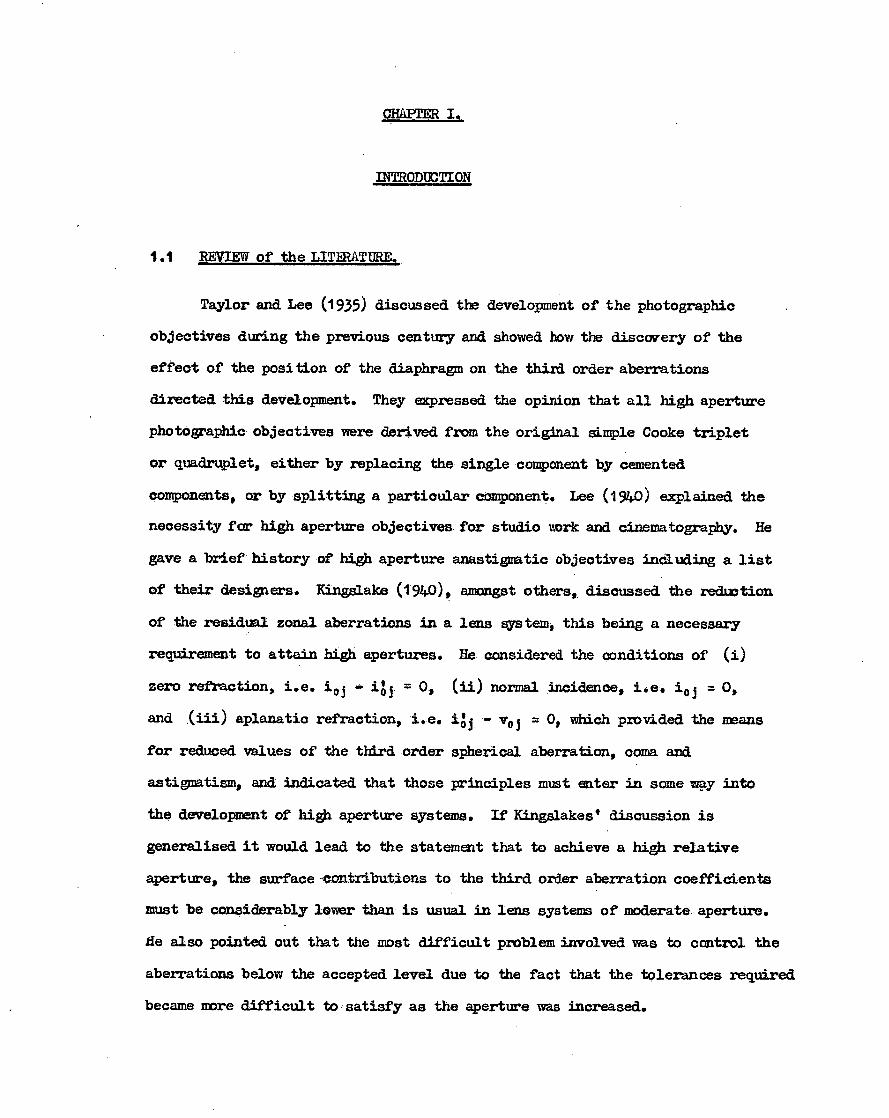
Taylor and Lee (1935) discussed the development of the photographic
objectives during the previous century and showed how the discovery of the
effect of the position of the diaphragm on the third order aberrations
directed this development. They expressed the opinion that all high aperture
photographic objectives were derived from the original ample Cooke triplet
or quadruplet, either by replacing the single component by cemented
components, or by splitting a particular component. Lee (1940) explained the
necessity for high aperture objectives for studio work and cinematography. He
gave a brief history of high aperture anastigmatic objectives including a list
of their designers. Eingslake (1940) amongst others, discussed the reduction
of the residual zonal aberrations in a lens system, this being a necessary
requirement to attain high apertures. He considered the conditions of (i)
zero refraction, i.e. Jo ig j = o, (ii) normal incidence, i.e. Jo = 0,
and (iii) aplanatic refraction, i.e. ilj - vo = 0, which provided the means
for reduced values of the third order spherical aberration, coma and
astigmatism, and indicated that those principles must eater in someway into
the development of high aperture systems. If Kingslakest discussion is
generalised it would lead to the statement that to achieve a high relative
aperture, the surface contributions to the third order aberration coefficients
must be considerably lower than is usual in leas systems of moderateaperture.
fie also pointed out that the most difficult problem involved was to control the
aberrations below the accepted level due to the fact that the tolerances required
became more difficult to satisfy as the aperture was increased.

2.
In a very detailed article Nerte (1943) reviewed the development of high
aperture objectives up to 1943. According to this reviewer the earliest
successful lenses belonged to the "Ernostar" series (Fig. 1.1), designed by
Bertele, but these were soon superseded by the "Sonnar" lenses developed by
the same designer (Fig. 1.2). Excellent objectives of this type were produced
having relative apertures of C(1.5 C/2 in focal lengths of 50 •- 100 mnu and
covering semifields up to 25 degrees. In addition to these, lenses of the
"Double Gauss" type (Fig. 1.3) had been extensively developed, resulting in
objectives of similar qpnlity.
Kimgelake (1944), (Fig. 1.4),explained the importance of glass selection
in high aperture anastigmats making special reference to the Ektar C/1.5 lens
designed by Schade. He stressed the importance of• using high refractive indices
for the positive elements, to form the collective surfaces in the cemented
components. This tended to smooth out the zonal residuals of axial and
oblique spherical aberration. The same author (1949), commedted on the
difficulty of designing a high aperture system, especially when it had to cover
a large angular field with a short focal length.
Kaprelian (1949) explained (Fig. 1.5) the necessity of avoiding strongly
curved surfaces (other than those which are splenetic or zero refracting). At
such surfaces the angle of refraction, 41, increases reapidly with the height
of the ray resulting in the development of very high values of higher order
aberrations. He also described in a condensed form how to control aberrations
with the help of glass constants and the stop position. He pointed out that
commercially produced lenses were more or less limited to the aperture range
g(t.5 - f/2 because of the practical difficulties of design and production.
Apertures greater than f/1.5 were only designed for special applications.

-3
AG. 1.3 BRITISH PATENT NO. 685 572/1936
IV II 25rnm
I20mm
15mm 24
20*
10mm 4 . 15.
40' 5mm
•5°
jar ni Ili RI 0 5° 15° 27 22°
•rvor -1 +1
FIG. 11 GERMAN PATENT NO. 441 594/1925
15°
20 .5*
1
10°
.3 0
5mm
. +50%
77-7 1179;RI0° -2 -1.13 -0.5
FIG 1.2 FRENCH PATENT NO. 837 616/1938
SK-T3 IF -S n = 15313 1567 w180 2.34
9(-1 1.610 177
SF-5 1973 310
9<-18 ism 1130
1.1F-6 1532 204
EK-32 1744 218 per cent FIG. 16 KODAK PROJECTION EKTAR f/1.5
FIG. 1.4 KODAK .. EKTAR . f/15
35MM
30mrn
2 5 mrn
20mm
15mm
Omm
50mm
•45mm
3 5mm
Omm
25rnm
Omm
15mm
•
10mm
5 mrn,
-to -its
FIG. 15 REFRACTION AT LARGE APERTURES
F/15
20

3.
Schade (1950) described the modification of the petzval portrait lens
(Fig. 1.6) in order to increase the aperture to get better resolving power,
contrast and back focal distance.
This review shows that there are very few papers which explain the
physical principles underlying the development of high aperture photographic
objectives and none which describes logical methods for their design. The
patent literature, of course, contains examples of the construction of such
systems, but here again, the physical principles leading to any particular
construction are not disclosed.
1.2 THE DESIGN of TRIPLET OBJECTIVIZ.
The purpose of this thesis is to investigate logical methods of developing
the design of high aperture systems from the Cooke triplet. In this connection
a twief resume of papers on the design of triplets is given.
Taylor (1895) arrived at the triplet construction by considering what
happened when the components of an achromatic doublet were separated. He
noticed that this separation increased the power of the system without increasing
the petzvel sum. To control the other aberrations he split the positive element
into two parts and placed one on either side of the negative element. He
obtained an ititial thin lens arrangement for the three powers and two
separations by solving five equations based on assumed residual values of
spherical aberration, petzval sum, longitudinal and transverse colour and the
total power of the system. He then constructed the system and measured the
aberrations. Using these measured aberrations he changed the original residuals
to obtain the final solution. Thus in view of this assessment the description
"optical designing - an art" was justified in the nineteenth century.

After Taylor, Schwarschild (1905), Kerber (1916), Berek (1930) and
Conracly (1960) described methods for the design of triplet objectives, but
in all these methods it was necessary to make repeated trials for the
determination of some parameter of the system.
Stephens (1948) developed the thin lens analysis of the triplet
taking into account both near and infinitely distant object planes. He
obtained a solution for prescribed values of the petzval sum, total power,
longitilAinAl colour, transverse colour and the height h3, the intersection
height of the axial ray at the third lens. He maintained the prescribed
values of the Seidel aberrations after thickening the system, and analysed
the final design by trigonometrical ray traces. His methodl however failed
to deal with the control of spherical aberration and provided no guide to the
important matter of the selection of glass for the lenses of the system. He
believed that the other triplet types, Helier, Pentac etc. could be generated
from the same procedures which he had used for the triplets.
Cruickshank (1956, 58, 60, 68) explaiped that all triplets with cemented
components could be generated from the simple Cooke triplet, or as he called it
type 111 triplet or basic triplet (Pig. 1.7). Thus in view of the fundamental
importance of the simple triplet, he developed the complete design theory, and
examined its properties in a detailed and systematic manner, including glass
selection. His method enables any newcomer in this field to design photographic
objectives based on the triplet family, methodically. According to him "The
triplet objective may be regarded logically as derived from the Wollaston lens
by the addition of a compound correcting system comprised of a positive and a
negative lens placed in front of the diaphragm". The main function of this

211 112
113 212
T iIll 111 k I
311
312
r
313
Li
IT" 1-7 321
1
ill r fAl ll L W) 121 221
rr7
122 222
/7". 232 132
TYPICAL TRIPLET CONSTRUCTIONS
133 Fig 1.7.

5 .
corrector was to introduce aberrations. Thus he replaced the h 3 parameter
of Stephens by the new parameter x, the power of the corrector. He also
showed (1968) that, for a given set of glasses and prescribed residuals, the
spherical aberration, spherical to seventh order could be approximated by a
quadratic function of x, thus:
spherical aberration = B3 x2 + B2 X + Bt 4. 0 ( )
where B3 B2 an 21 are cnastants. The values of x for which the lens system
has a resiAual spherical aberration up to seventh order of amount Hi are the
roots of the equation
Bar + X + — i, =o (1.1)
Cruickshank's initial solution for the three powers and two airspaces was
based on prescribed values of x, petzval sum, total power, longttudinal and
transverse colour. He gave the complete design procedure for an infinitely
distant object plane and then introduces modifications for finite conjugates:
In 1960 he discussed in detail the general physical principles of the
generation of triplets with cemented components. He illustrated this with an
example of a Pentac (type 212) objective developed from a typical set of
aberration residuals and fictitious glasses. He included graphs showing the
variation of the fifth order coefficients of the Pentac system with x, Which
indicated very clearly the optimum value of x. This example illustrated the
use of the fictitious glasses in obtaining the initial solution of a triplet
system with cemented components and also the use of the Buchdahl (1954)
aberration coefficients as a measure of the correction state of the design:
It showed clearly the advantage of being able to see the trend of the design
using fifth order coefficients.

6 .
Cruickshank and Hills (1960) have show' how the aberration coefficients
developed by Euehdahl (1950 may be used in the development of the design of
an optical system. In this connection the essential feature of these
coefficients is that irrespective of order they are obtained by a summation
over all the surfaces of the• system.
In his 1958 paper Cruickshank developed a cubic equation for the r/
determination of the initial arrangement. He noted that "In general only
one root of this equation gives a physically useful solution. There is an
rtant exce tion however in one case in which a second root leads to the
possibility of the construction of another group of objectives of high
aperture."
In this thesis an account is given of an attempt to investigate this other
group of objectives in detail. It was hoped that this would provide a logical
starting point for the development of high aperture systems.

ihroa 413'0 = 41 a
1hroa Li (PjYaj = X a
1/2
(2.1)
(2.2)
=R4 (2,3)
CHAPTER II.
2.1 RY of the BASIC
It has been stated in the previous chapter that any system of the triplet
type has an equivalent triplet, or, as we shall call it, a Basic Triplet. In
this section me will summarise the important practical case of the initial
design of a triplet photographic objective corrected for an object plane at
infinity, as given by (1958). This summary will introduce most of
the required notation. The three lens components a, b and o have the glass
constants (Na , Va ), (Nb, Vb) and (ti c , Irc ) respectively. Disregarding the axial
thicknesses of the leases, five variables are required to specify the system
initially, namely the powers 98, (Pb, 9c and the separations ti and t2 of the
three coaxial lenses. The following five conditions may then be fulfilled:
(i) The power of the system shall be unity; (ii) The power of the corrector
shall be x; (iii) The system shall have a petzval curvature coefficient, c14- = R4 2
for the petzval sum; And for the object plane at infinity the system shall have
(iv) A residual longitudinal paraxial chromatic aberration, R62 and (v) A
residual transverse chromatic aberration Et" for an incident pencil of obliquity,
va , the diaphragm being coincident with the central thin lens b. Using well
known relations for systems of separated thin lenses in air these five conditions
may be formulated analytically as follows:

jeo = R6 (26)
p i yo i yj = R 7 (2.5) 3-a
Where yj and yo j are the incident heights at the jth component of a principal
paraxial ray (b-ray) of obliquity va , and an axial (a-,ray) paraxial ray
respectively, and vld is the inclination angle of the axial ray after refraction
at the jth component. Since the diaphragm is initially in coincidence with the
second thin lens of the system, the incident heights of the principal paraxial
ray are such that
4/4 = -t1n2 ; Yob = 0 ;
(2.6)
while for the axial ray
Yob = Yea - tivla = Yoa( 1 4a ) (2.7)
Yoc = •Yob tdC (2.8)
A substantial reduction in the symbols specifying the glasses of the system is
achieved by writing
liAlb =0; Na/Nc = Y •
In addition we can also write
2Relia = P (2.10
F1/4 71To = L (2.11)
14.7Vo =T (2.12)

(2 .13)
(2. 14)
- (2.15)
(2.16)
(2.17)
9a + Yob91) + Yoc9c = 1
9a + Yob96
9a + PT!) + Ytk
9a+ iraYtt9b + Eroc9c =
(1 + T)tt 9a - t2E3r0c9c =
with this notation equations (2.1) - (2.5) now become
9 .
The solution of equations (2.13) - (2.17) is quite easy. Equations (2.13) and
(2.14) give at once
(2.18)
(2.19)
(2.20)
(2.21)
(2.22)
(2.23)
(2 .24)
Yoc9c = 1 - X
and combining this with equations (2.17), (2.6), (2.7) it follows that
tt =(i Yob)/9a
t2 = 11 - (1 + T)yobiA(1 -
Combining equations (2.8) and (2.11) gives
Kyob C( 1 — thoc = x
where K = +X(1 + T E)
Subtracting (2.14) from (2.16) yields
9Wob(aYob - 1 ) + - X)3roc = L X
which on combination with (2.21) gives
91) = (K3ra1 - 1,)/( 1 Wrob )Yob

10,
Equations (2.18), (2.8) and (2.20) together give
(pc = — 02 Acyob — x)
(2 .25)
while equations (2.14) and (2.24-) give
(Pa X Yob9b
+ X - (K ctX)Yobl/( 1 aYob)
(2.26)
If q . (pc are now eliminated from equation (2.15) by means of equations
(2.24) - (2.26), we obtain the cubic equation
Gollb + Cieob + Coro t) +G0 = 0 (2.27)
where GI = +coc(x - P) (2.28)
= ic(P - L 2x - pc) + alyE (1 - )2 x (2.29)
= pic(x +L) - lyg(1 x)2 - x (x -)1 + Lx (2.30)
Go = (2.31)
This cubic equation will have three roots, so that three initial arrangements
may be possible. The coefficients can be computed for the given residuals and
the roots can be obtained by successive approximation.
From the initial solution, three shapes So , Sb, Sc corresponding to
powers cat (Pb' T c are available to control three characteristics of the system.
The analystical theory (Cruickshank, 1968) shows that one can calculate three
thin lens shapes So , Sb, Sc of the basic triplet to achieve the specified
third order aberration residuals 172 , R , E4 for coma, astigmatism or flat
tangential field condition, and distortion.

it.
It will be seen in general that the third order aberration coefficients
in the thickened system0.2 , e4 or Os = 303 + 04 , will differ from the
corresponding specified residuals R2 , R4, Rs of the thin system. A stage of
differential correction is therefore required. In the light of this fact, it
is just as effective to introduce arbitrary, but reasonable, shapes in the
thin lens system, carry out the standard thickening procedure and use the
differential correction method to adjust shapes in order to achieve the
prescribed residuals 1 26 R." E4 in the thickened system.
This method is quite convenient with the above assumed stop position
because the shape change at any lens affects only the contributions of that
lens to the third order aberration coefficients.
It is essential to prescribe some residuals R6 and R7 to minimise the
longitudirAl chromatic aberration near the 0.7 -• 0.8 zone of the full aperture
and to correct the transverse chromatic aberration at some field angle using
the wavelengths for which the system is to be achromatised. It mill be seen
in general that the paraxial chromatic aberration residuals B.67 B7 of the thin
system differ from the corresponding traced values l c h, tc h of the thick
system. To achieve the prescribed residuals in the thick system the same as
in the thin system, the tso parameters L and T are adjusted with differential correction
method by forming the derivatives al c h/aL and at c hAT.
Finally, we adjust the spherical aberration to seventh order for the zone
of radius p to such a value that the total spherical aberration of the system
is suitably corrected. The parameter x is used for this purpose.
The main advantage of this basic triplet theory is that the above procedure
can be applied to design any triplet of the basic triplet family shown in Figure
17 of Chapter I.

12.
2.2 A STUDY of the ROOTS of the CUBIC EQUATION.
The equation (2.27) is of the form f(yob) = 0, where f(Yob) is a .
cubic polynomial. The coefficients of the polynomial are cagplicated
functions (see equations 2.6 to 2.31) of the glass constants and. the
residuals of the system. The analysis of the dependence of the roots of
this equation on these quantities is therefore a complex problem. It is
fairly obvious that certain of these quantities have a greater range of
variation than others. Among these area, P and The ratio 190/ = a
can be varied quite widely. A doublet as the first component may have an
effective 11-value (see section 3.1) anywhere from 40 to 300 or more quite
easily, while a negative doublet or triplet for the central component may
have an effective Ih-number as low as 10: It is clear, then, theta can be
Varied continuously in practical systems: The ratio "cloth = E can also be
varied continuously in the same way by replacing the last component by a
cemented doublet or triplet, but the range of variation is more limited.
The ranges of variation for and y, ratios of refractive indices, are
much more limited still. We shall find, that the parameter P can be increased
considerably beyond the ordinary value (about 0.6), Which it has in normal type
111: triplets. It should be remembered that P = 2N4Na, where N4 is the third
order petzval curvature coefficient in the thin lens system. The replacement
of. thin lenses by thick ones may often result in a reduction of the petzval
sum, especially if meniscus and thick cemented components are used. It is
therefore not unpractical to consider values of P up to about Wice the value
which is usual in the type 111 triplets, provided the thick lens replacemeuts are
designed with a reduction of petzval sum in mind. This point is considered
further in Chapter III.

1 3.
In Fig. (2.1), curve (1) is the graph of the polynomial f( %Yob)' and its
intersections with the yo b axis give the three roots of the equation f(yo b) = O.
The curve has been drawn for values of the residuals such as might be used in
the design of a type 111 triplet. In particular, P has the value 0.60. Of the
three positive roots, it is clear that only the second root yo b = 0.84 provides
the basis for a practical system. The first root Yob
undesirably high powers far the components; while according to equations (2.19),
(2.20), the third root, y o b greater than unity, would give negative values for
both air spaces.
Curves (2), (3) and (4.) in Figure (2.1) are similar graphs of f(yob)
corresponding to the values P = 0.8, 1.0, 1.2 respectively. An interesting
feature is that an increase in P results in the reduction of the value of the
third root of the equation and raises the question as to whether this third
root can be less than unity. Curve (4) shows that increasing P to the value
1.20 does not produce the desired result, for in this ease the curve falls
below the yo b axis. The cubic equation then has only one real positive root
Yob = 0.02, which is not of practical use. A third root of the equation less
than unity cannot be obtained simply by increasing P for this set of residuals.
Figures (2.2) and (2.3) which are drawn for the cases in which the power x
of the corrector system has values of -0.2 and +0.2 respectively, show that the
variation of this parameter with these residuals and glass constants does not
alter the situation significantly.
We consider next the effect of the variation of the glass parameter a
in the range 1.4 to 5.0, say. This could mean, for example, that we are allowing
the effective V-number of the glass of the central component to be reduced
= 0.045 would lead to

f (Yob)
X =-0.60
Yob
(3) (2) (1) (4)
8
7
6
5
4
3
2
0
2
3
- 1.0 - 0.5 0 0.5 1.0 1.5 2.0 2.5 3.0 3.5 4.0 4.5
FIG (2.1)
The effect of the variation of P on f(yob) Vs yob curves in type 111 triplets
GLASSES:
SK 6 1.6163 56.11
BASF10 1.6541 38.87
SK 6 1.6163 56.11
GLASS CONSTANTS:
c<= 1.4435, /3 = 0.9772, E =1.0 -1.0.
RESIDUALS:
L=0.1, T = 0.0 .
(1) P =0.6, (2) P :0.8. (3) P =1.0 . (4) P =1.2.

(2)
(3) (4) Yo b
- 1.0 - 0.5 0 0.5 1.0 1.5 2.0
2. 5
3.0 3.5
4.0 4.5
FIG (2.2)
The effect of the variation of P on f(yob) Vs yob curves in type 111 triplets
GLASSES: SK 6 1.6163 56.11
BASF10 1.6541 38.87
SK 6 1.6163 56.11
GLASS CONSTANTS:
= 1.4435, /3 0 .9772, 4 =1. 0, r 1.0 .
RESIDUALS:
8
7
6
5
4
3
2
0
2
3
T = 0.0 .
(1) P0.6, (2) P = 0. 8, (3) P =1.0, (4) P 1.2.

(1) (2)
X = 0.20
f(yob )
(3)
Yob
(4)
8
7 .
6
5
4
3
2
2
3
- 1.0 - 0.5 0 0.5 1.0 1.5 2.0 2.5 3.0 3.5 4.0 4.5 Fig (2.3)
The effect of the variation of P on f(yob) Vs yob curves in type 111 triplets
GLASSES:
SK 6 1.6163 56.11
BASFIO 1.6541 38.87
SK 6 1.6163 56.11
GLASS CONSTANTS:
O(: 1.4435, /3 =0.9772;4 =1.0, f =1.0.
RESIDUALS:
L=0.1, 1=0.0.
(1) P=0.6, (2)P :0.8 (3)P =1.0, (4)P =1.2.

14.
progressively. Such a variation could be achieved practically if the single
negative component were replaced by a suitable negative doublet or triplet.
In Fig. (2.4(a), curve (1) shows the result of increasing a from its
earlier value of 1.44435 to 3.00000, P having the value 1.10. The equation
f(ye b) = 0 now has three real roots between 0 and 1, and the possibility of
a new basis fora practical lens system arises. Curves (2) and (3) show the
graphs of f(yo b) for the cases in which a has the values 3.5 and 4.0
respectively. Investigation of the initial thin lens solution corresponding
to the new third root is not very encouraging, far, as Figure 2.4(b) shows,
the power of the first component and the first air space are both negative.
These will not provide a practical lens system.
Fig. 2.5(a),(b), show similar curves resulting fram changing the value of
x from-0.6 to -0.2. From Figure 2.5(b), it can be seen that the first
component now has a small positive power and the first air space is now also
positive, but large. This suggests that further investigation of the effect of
the increase x should be made.
With this in mind,X was increased to +0.20 and the corresponding curves
are represented in Fig. 2.6(a),(b). It can be easily observed from Fig. 2.6(b)
that the initial solutions have become much more practical and offer promise of
a reasonable basis for a lens system.
Because of the important part played by the parameter cc , it is more
informative to present the results obtained so far in graphs in which a is the
independent variable.

t t2
- 0.2 0 0.2 0.4 0.6
Fig 2.6(a)
0.8 1.0 0 3.25 375 4.25 4.75 5.25
Fig 2.6( b)
\
if(yob)
. (1) (7)
Yob
(1) (2) (3)
d = 3.0
04 = 3.5 04 = 4. 0
z :0.20 (3)
-0.2 0 0.2 0.4 0.6
Fig 2.4(a)
0.8 1.0
-0.2 0 0.2 0.4 06 Fig 2.5(a)
0.8 1.0
1 f (yob) -
Yob
(1)
(21_ (3) Z = -0.6
(1) (2) (3)
(34 = 3.0 04 = 3.5 c4 = 4.0
I
I f(yob) Yob
(Tr (2)
(3)
(1) 04 = 3.0 (2) 04 :3.5 (3) 04 = 4..0
X r0.2
1 i
0.4
0.2
- 0.2
-0.4
- 0.6
- 0.8
0.8
0.6
0.4
0.2
- 0.2
- 0.4
0a
t 2
0,
0 b
t i
° b
t i
2
0 3.25 375 4.25 4.75 5.25
Fig 2.5(b)
2.0
INI T
IAL
SO
LUTI
ON
PARA
METE
RS
3.25 3.75 4.25 4.75 5.25
Fig 2.4(b)
ct
- 1.2
- 1.6
1.4
1.2
0.8
0.4
-0.4
-0.8
0.8
0.4
INIT
IAL
SOLU
TIO
N P A
RAM
ETERS
1.2
-0.4
(4 ,0
-0.8
0.6
0.4
0.2
- 0.2
- 0.4

15.
Fig. 2,7(a) shows the roots of the cubic equation (2.27) as a function of
a, for different values of P. Curves (1) and OP are drawn for the case in
which P = 0.6. These curves show the variation witha of two of the roots. The
remaining root which has a value close to zero and has no practical significance
is not shown. If a triplet is designed with P = 0.6 then the root of the cubic
equation on which it is based must lie on the curve (1) because this is the only
useful root below unity. Curves (2) and (2)' show the corresponding roots for
the case in which P = 1.0. It can be observed from curve (2)' that the values
of the roots represented in this branch are much reduced compared with the values
summarised in curve (1)'. On curve (2)t however, all the values still lie above
unity. If P is increased to 1.05 it becomes clear that a change has occurred in
the solution of the cubic equation, resulting in the roots lying in the continuous
curve (3), provided ct7.2.15. In curve (3) for a2.15 we obtain two positive
roots for each value of cc and these both have values below unity. The smaller of
these two roots belongs to the general conditions represented in curves (1) and
(2,, on which the design of the traditional triplet is based, while the larger
most correspond to a set of new conditions which may lead to another class of
triplet solutions. The effect of increasing P beyond 1.05 can be seen in curves.
(4), (5) and (6), which are drawn for the P values 1.1, 1.15 and 1.2 respectively.
The new conditions represented in the upper portions of these continuous curves
will be the main subject of further investigation.
From the values of yo b on the continuous curves (3) (4.) and (5) are
computed the powers itp o , 9b, cc and the separations t i , t2 of the basic thin
triplet, using the appropriate equations from (2.19) to (2.26). The results
of these computations are plotted in figures 2.7(b) to 2.7(e). The interesting
feature of Fig, 2,7(b) and 2.7(c) is the great reduction in the powers of the

Fig 2.7(a)•
1.0 1.5 2.0 2.5 3.0 3.5 4.0 4.5 5.0 5.5
(1)
(2)
(2) (3)
(4) 5)
NT
(6)
'\\ N
The effect of the variation of P on the
the cubic equation (2.27).
positive roots of
P-0.6, (1) (2) P-1.0, (3) P=1.05, (4) P=1.10,
(5) P=1.15, (6) P=1.2.
The remaining glass constants and residuals are as follows..
4. = 1. 0, 4 =0.9772,
r =1.0, 7c =0.2,
1=0.1k 1:0.0.
7.0
6.0
5.0
4.0
3.0
2,5
1.2
1.0
0.8
0.6
0.4
0.2
0
0.2
0.4

(5) (4) (3)
-4.0
0
1.0 2.0
3.0 4.0
5.0 6.0 ..
Fig
2.7
(e)
Fig
2.7
(b)
1.0 2.0
3.0 4.0
5.0 6.0
Fig
2.7
(c)
The v
aria
tion o
f Initia
l Solu
tion p
ara
mete
rs
corre
spond to
the v
alu
e o
f the ro
ots o
n cu
rves
(3), (4), and (5
) in fig
(2.7
a).
(4)
1.0 2.0
3.0 4.0
5.0 6.0
Fig
2.7
(d)
(5)
(4) 0.1
(3)
0.2
GC.
2.5
0 0
LU
_.1 _0.5
LU
0
c3j -2
.5
-3.0
-3.5
1.5
1.0
•0.5
•0
1. \0 20
3. 0 4
2.0
POW ER OF BACK LENS, Ø.
2.5
2.0
1.5
1.0
06
0 6
0
(1.5
0.4
0
0.6
0.5
0.3
0.2
0.1
FRONT AIR SPACE t • 1 -
0.3

16.
components corresponding to these yo b-values. The curves of t, and t2 which
have lower slopes are associated with yob-values in the upper portion of curves
(3), (4) and (5) in Fig. 2.7(a). All these results look promising for the
existence of a new class of solutions, having much lower powers than in
traditional triplets.
The coefficients of the cubic equation (2.27) are not only functions of
x, P and a considered so far, but also of E, 0, y, L, T. although the ranges
of variation of these are more limited, the effects of their variations must
be investigated. In doing so we shall limit our considerations to the roots
represented by the upper portions of the continuous curves.
Figures 2.8(a) to 2.8(e) show the variations of the powers pa, Pb , pc
and the separations t , t2 , respectively, regarded. as functions of a for
different values of E far the case in which P = 1.10. Curves (1) (2), and
(3) are drawn for the C values 1.0, 1.2 and 1.4 respectively. These figures
show that the powers of the components change considerably with increase of E,
especially (pa and (Pb , whereas the values of the separations t, and t 2 do not
vary significantly. The minimum value of a for which solutions are possible
increases with C.
We consider next the effect of the variations of the &ass parameters
• Vhb = and lia/Nc = y. This could mean, the generation of fictitious glasses
(see Chapter III, Section 3.1) in the replacement of single components by
cemented components.
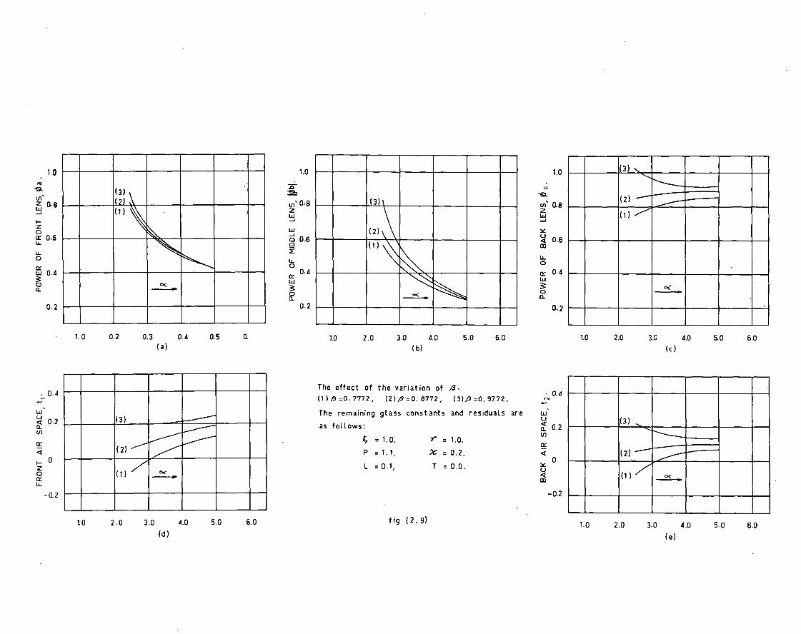
In Figures 2.9(a) to 2.9(e) curves (1), (2) and (3) are drawn for different
values of 0, namely 0.7772, 0.8772, 0.9772. These are similar to Figures 2.8(a)
to 2.8(e), and show that increasing 0 will increase the thin lens separations and
the power pc much more than the powers pa and Pb .

1.2 1.2
1.2 ( 2
• 1.0
LU
0.8
cr u- u_ 0.6
LU ce
004
(2)
(2 )
t; 1.0
Ln'
LU - 0.8
w 06
LU
0 0.4 a_
(1)
(3) ( 1 )
(3)
o(
a 0.4 a-
0.2
0.2
0.2
1.0 2.0 3.0 4.0 5.0 6.0
(a)
1.0 2.0 3.0 4.0 5.0 6.0
(b) 1.0 2.0 3.0 4.0 5.0 • 6.0
(c)
(2) (3) (1).
■■■$,•
1.0 2.0 3.0 4.0 5.0 6.0
(d)
The effect of the variation of 4. (20.4
(1)4 =1.0, (2)4=1.2, (3); =1.4. 4
The remaining glass constants and residuals are
as follows: c,
▪
02
4 = 0,9772, r = 1.0,
L = 0.1,
ZT ==00..20., • 0
P =1. 1,
fig (2.8).
(2)
o(
1.0 2.0 3.0 4.0 5.0 6.0
(e)
(3)
(2)
(1 )
3.0 4.0 (e)
1.0 2.0
(3)
1.0 2.0 3.0 4.0 5.0 6.0 (c)
5.0 6.0
1.0
2 0.8
cc 06
IL
u_
w 0.4
uls 0.8
O 0.6
IL
• 0.4
1.0
0 2
(3)
0.3 0.4 (a)
1.0 0.2 0.5 0.
0.2
w 0.2
ce
0
(3)
(2)
- 0.2
tO 2.0 3.0 4.0 (d)
5.0 6.0
. 0.4
1.0 2.0 3.0 4.0 5.0 6.0 ( b)
The effect of the variation of • • 0.4 (1)/3 =0.7772, (2)fi =O. 8772, (3)/3 =O. 9772.
The remaining glass constants and residuals are
as follows: a_
•
0.2 4 = 1.0, = 1.0, P =1.1, X =0.2,
L =0.1, T =0.0.
•
0
co
-02
flg (2.9)
1.0
-Q. cri 0.8 Ui
< 0.6
IL
co
cc 04 Li
0.2

0
•••■
POWER OF BACK LENS, 0 c •
co CO
BACK AIR' SPACE, t 2
'ZLL
6'0 =
V
IA
—et 0
0
in
The rem
aining gla
ss constants
and
resid uals are
POWER OF FRONT LENS, 0 2 ,
P o P P _. ,..)
FRONT AIR SPACE, t i ,
oo 0) CO
POWER OF MIDDLE LENS, Icibl
LI

1.0 2.0 .30 40
(b)
2.0 1.0 2.0 3.0 4.0 5.0 6.0
( 2 )
3.0 4.0 (c)
5.0 60 5.0 6.0
1.0 2.0 3.0 4.0 5.0 6.0 (e)
3.0 4.0 (d)
5.0 6.0 1.0 2.0 fig (2.11)
The effect of the variation of L.
(1) L=0.1, (2) L=0.3, (3) L=0.5,
The remaining glass constants and residuals are
as follows:
4 = 1.0, /3 =0.9772,
r = 1. 0, P =1.1,
T =0.0.
• CV 0.4
Ui
a. 0 2
cc
<0 CD
1.4
(f) z 1.2 Ui
a) 1 . 0
U- 0
08
0 a.
0.6
0 E 0.6
a_ 0 2
0.8
0-1 0.4
° 0.2
(1) (2)
( 3) eb<
.11.•■■
(1)
(1)\ (2) (

1.2 1.2
. 1.0
6 0.8
0 cc 0.6
LL
u_
ce w 0.4
a_
02
0,c
0.2
1.6
(2)
c<
0 6
( 1 )
1.0 2.0 3.0 4.0
(a)
1.0
2.0
3.0 4.0
(d)
1.0 2.0 3.0 4.0 5.0 6.0 (b)
The effect of the variation of T.
(1) 1=0.0, (2) 1=0.2, (3) 1=0.4.
The remaining glass constants and residuals are
as follows:
4 = 1.0 , fi =0.9772.
r 1 . 0, 0.2,
P = 1. 1, L :0.1.
fig (2.12)
1.0 2.0 3.0 4.0
5.0 6.0 (c)
1.0 2.0 3.0 4.0 5.0 6.0 (e)
5.0 6.0
5.0 6.0
06
(3)
- 0.2

17.
Similar curves (1), (2), (3) in Figures 2.10(a) to 2.10(e), drawn for
the values y = 0.8, 0.9 1.0 respectively, show that the increase of y will
decrease the values of all the parameters of the initial solution. The
reductionsin the airspaces and in the powers Icbl and cc are more noticeable
than the reduction in c a .
The parameters L and T cannot be chosen as degrees of freedom in the
same way as the glass constants because R and 134 are to be prescribed to
control the chromatic aberrations of the system. However, variations of these
are considered at this stage because the values of L and T in the new class of
triplets may differ considerably from the corresponding values in the type 111
triplet objectives on account of the presence of compound components.
In Figures 2.11(a) to 2.11(e) the curves (1), (2), (3) for which L has
the values 0.1, 0.3, 0.5 respectively show the resulting change in the powers
and the separations. These do not call for any particular comment. Figures
2.12(a) to 2.12(e) show the effects of the increase of T. The curves (1), (2)
and (3) are drawn for T values of 0.0, 0.2 and 0.4.- It can be seen that the
main result of increasing T is an increase of the first airspace, t it together
with a substantial decrease of the second airspace, t2 , which has even become
negative in two of the cases considered. It will wear subsequently that
advantage can be taken of this effect of T in a very interestinstLganner.-

CHAPTER III
GENERAL PROPERTIES OF .THE NEW CLASS OF OBJECTIVES
3.1 SOME PROPERTIES of CEMENTED TRIPLETS of NEGATIVE POWER.
In his discussion of the triplet family of objectives, Cruickshank
(1958, pp27-29) has shown that any thin lens (T,R,i) of power ç and with
glass constants awl in the basic triplet can be replaced by a set of thin
lenses Oct qoaNi sIrt ( Ic2 (PA 01.2 ) (kn , 11nNe) in contact, the replacing group
having the same power, the same petzval sum and same paraxial chmratic
aberrations as the singlet it replaces, provided that
4 + 4 . • • k = ( 3 . 1 )
10; %/N2 4- • • • knAln =
(3.2 )
+ k2/v2 + . . . kriv, = ifv (3.3)
This means that it is possible to design a cemented component, which is
equivalent as regards power, petzval sum, and the paraxial chromatic aberrations
to a thin lens having within a certain range any value of N, and, independently
thereof, any value of V. The artificial glass refractive index generated in
this may is known as a fictitious refractive index &Di the i-numberproduced is
called the effective V.-number.
In order to maintain the same power, the same petzval sum, and the same
chromatic aberrations as the singlet it replaces and to obtain variation over
a considerable range, for the important parameter a in the new class of thin
lens initial solutions discussed in the previous chapter, we replace the
central thin lens ((pb,k,ib) in the basic triplet by a set of three thin lenses
(kopb,N,A ), (k 2 cpb,N2 „Iir2 (k391),N3,V3) in axial contact. Them the equations
(3.1) - (3.3) become

19.
ks +k 3 =1
(3.4)
1C2/1\12 Ifs = 14b
(3.5)
Ic /v, + k2/v2 + k, /113 = (3.6)
The three unknowns ILI ,k2 ,k 3 for a given set of glasses can be calculated
for any value of "rfb and ilb, i.e. for any value of a and from equations
(3.4) - (3.6). The values are given by
= 46.1 /63 K2 = ; K3 A3A
= 1 1 1
lAb 1/112 1/143
vv2 i/v3
1 .1 i
i/N, 1/171b i/B3
i/v, 1filb 1/113
1 .1 i
f/N, i/N2 inft,
1/v1 1/112 Viih r
=
1/112 i/N3
1/v2 1"

20.
Multiplying the power cb by k1 1k2 ,1c3 in turn, we obtain the powers of the
individual components of the replacing triplet.
To avoid an excessive number of air-glass surfaces, we may decide
that the components of this triplet should be cemented together. When the
shape factor of one component is arbitrarily selected; the shapes of the
remaining components are then fixed by the cementing condition. There is
thus only one shape factor for the compound component. We shall use the
shape of the front component of this cemented triplet to specify the shape
factor of the whole component.
It mill be remembered that we increased the value of P in the thin
basic triplet system, assuming that the replacement of a thin component by a
thickened meniscus cemented component may often lead to a reduction of the
petzval sum of the Whole objective. We study, therefore, the variation in
the value of the petzval curvature coefficient e4 of a cemented negative
triplet with change of shape.
In Figure3.1, curve (1) is drwan for the case in which
(1) =•—1,
Elb = 1.8381, Vb = 19.4233
In this figure, we have not plotted 04 itself, but the related quantity 2m4Nb *
which is the value of the parameter P, for this component. The curve shows
that as S increases the value of P becomes more negative.. Similar curves (2)
and (3) are drawn for the cases
(2) 9 = .1, gb = 1.8381, . 16.6486
and (3) = -1, gb = 1.8381, = 14.5676

0 0.5 1.0 1.5 2.0 2.5 3.0
3.5 4.0 4.5
Fig 3.1
_ -trip = 19.4233
Vb = 16.6486
( 1)
GLASSES:
1.65426 58.27 1.50349 56.15 1.67158 32.76
CEMENTED FII)=1.8381 TRIPLET
\TID = 14.5676
( 3 ) ( 2)
I
- 10
- 1. 5
-2.0
-3.5
-4.0
-4.5

21.
respectively, and these curves show P to be changing more rapidly with S than
curve (1). It becomes clear, then, that the negative contribution, which the
thickened cemented triplet makes to the value of the parameter P can be
substantially increased by change of its shape and by reduction of its
effective V-number il) ; Our next consideration is to know the particular
surface or surfaces of this wripmand triplet; responsible for the reduction
of P. It is observed that the last curvature of this compound triplet turns
out to be deep with increase of shape and produces very high negative values
of P. The P values of the last surface corresponding to the case (2) in
Figure 3.1 are computed; and these results are represented by curve (3) in
Figure 3.2. The curve (2) in Figure 3.2 is the sane as the curve : (2) in
Figure 31 which is draun for comparison.
The use of a cemented triplet having a positive shape factor and low
value of Vb as the central component in a triplet objective results in
reduction of the P-value of the whole objective, because the P-value is
unaffected by the object position. This fully justifies our earlier assumption
that larger values of P used in the basic triplet initial solution could lead
to useful practical solutions.
We will now study the variation of the locations of the printipal points
of the cemented negative triplet. To do this, the principal point distarces
are computed for the components given in cases (1) and (2) of Figure 3.1, and
the results of these computations are plotted in Figure 3.3 as functions of S.
For case (1), curves (1), (1)t represent the variation of first and second'
principal point distances with increase in S. The effect of decreasing VI) can
be seen in similar curves (2),(2)° drawn for case (2). All these curves show
that the first principal point distance is always greater than the second
principal point distance for a given value of 'lb and S.

Lf) va
q c:
0 cri
■■•■•■ C•4 ...—.
./ z z /
/ ao•■••
r)
LC) Ul cm.
Cv) VIZ I 1 1 I o
d

PRINCIPAL POINT DISTANCES lpb, lipb.
P cri
P •■•• 0
r.. P ul
P a) 0 CO
Ni Vb = 19 . 4233
=16.6486 % N (1) ,
(2)'

22.
3.2 SI31EllaRY of the NED7 CLASS of TRIPLETS.
The new region discussed in Chapter II was arrived at in the initial
solutions of the basic triplet by increasing the normal values of the
parameters a, P, and x. Increasing ot means decreasing the V-number of
the central component of the basic triplet for a given V-number of the first
component. The only way to fulfil this condition for a given V-number of
the first component of the basic triplet is to replace the central thin lens
of the basic triplet by a compound component.
In order to maintain the same power, the same petzval sum and the sane
chromatic aberrations as the singlet it replaces, one has to replace the
central thin lens of the basic triplet by three thin lenses in axial contact.
The large values of P used in the initial solution will be reduced to an
acceptable level in the actual system of the whole objective if a positive
meniscus shape and low VI, of the central compound component are maintained.
This central compound triplet with positive meniscus shape will have its
principal points at a considerable distance from its vertices. It is clear,
then; that these triplet j.ives with a thick cemented central triplet must
have, in the initial arrangement, a high positive value of t i to accommodate
this central component, and a low or even negative value of t2 to maintain a
compact objective. The tmall of the distribution of principal points in the
class of triplet objectives are illustrated in Figures 3.4(a) and 3.4.(b).
While we investigated the initial solutions in the last Chapter, we
noticed that a high positive value of t s and a low or even negative value of
t2 could be obtained by increasing the parameter T. It follows, therefore,
that the required positive value of ti and low value of t2 can be provided in

4.1■■••
c.) ....■■•
_0 0. =MP
c., 4,
_0
.. 0-
...............................„............ ..................................................4
'----■----_---------

.0 a. •••Illm moo
40.1
MIND ■ND ■•■ 4■1.
CNI =Mr. MEM •■••
4-0
co ■11, ■••■• ONO OEM. ■11, 4■0. MOM

23.
this class of objectives by giving an appropriate positive value of T in the
initial solution. But the next question is -whether this value of T is
consistent with control of the transverse colour.
- We begin to see now how the important parameters 0, P and T are
interrelated to control the over all optical characteristics of this class of
objectives. With a thorough understanding of the effects of these parameters,
together with the effects (studied in the second chapter) on the initial
solutions of the other parameters, we are in a position to progress towards
practical solutions for this class of objectives.
The design of this class of objectives should start then with the
selection of reasonably high values of a, Po x, T, along with moderate
values of the other parameters. This should give a suitable initial
arrangement with large front air space and small rear air space. Next, the
central component in the basic triplet is replaced by a compound negative
triplet and this should give possible triplet objective belonging to this
new group, i.e. this group starts with the type 131 triplet. The remaining
triplets of this family could be 132, 133, 231, 232, ... etc. The
replacenent of components other than the central component by compound
components provides more degrees of freedom and one can expect better
performance with increased aperture and wide field, compared to the optimum
131 triplet.
In the next Chapter, we try to develop the practical application of these
ideas by considering the design of 131 triplet objectives.

CHAPTER IV
AN INVESTIGATION OF THE DESIGN OF A 131 TRIPLET
4.1 DESIGN PROCEDURE.
We begin with the five selected glasses (N8 ,V8 ), (NI ,Y1 ), * (N2 ,112 ),
(N3 ,V3 ), ti.c:„Vc ), the residuals R4 ,R6 , R7 corresponding to P, L, T and the
parameters a, O s X which will lead to a solution lying in the new region
suggested in Figure 2.7 of Chapter II. Along with these, the resiauAls
R2 , ES and Rs are selected (normally zero values at the initial stage) and
the basic triplet initial solution parameters 9a , 9b, 9c , tl , t2 are
computed by using the appropriate equations (2.19) - (2.26) of Chapter II.
Having done this, the glass constants 4, Vb can be evaluated from equations
it) = 13/N8 , Vb = a/Va . Using these constants, the three constants k ip k2 ,, k3
will be calculated by solving three simultaneous equations (3.4) - (3.6) of
Chapter III. Then the three thin lens powers Pb1, b2s are calculated 9
from the equations cb t = kopb, 9132 = 1 2 9b, 9ba = k3 9b. These power
calculations complete the replacement of the central thin lens of the basic
triplet by three thin lenses in axial contact, i.e. the basic thin triplet is
converted into a thin 131 triplet having the same initial residuals and values
for x,P, L, T as the basic triplet.
The next step is to compute the thin lens curvatures of the 131 triplet
for a set of three arbitrary shapes S ao Sb, Sc . The thin system is then
thickened, introducing the prescribed axial thicknesses d 2 , d4 , da , ds of
the five components, using Cruickshank's (1968) standard thickening procedure,
which keeps the total and the individual powers of the three thick components
a, b, c equal to the totand the individual powers of the corresponding thin

25.
components. The two standard paraxial rays, i.e. the axial paraxial ray
(3701 = 1, vo, = 0) and the principal paraxial ray (yl = p, V1 = 1) for the
allotted stop position (fixed initially at the first principal point of the
central compound)', for an object plane at infinity are traced through the
system. From the results of these two traces, we compute the third order
aberration coefficients 04, 0a 6 03, 04. 05 and, for convenience, .06 = 303 + 04.
The next step is to adjust the three available shapes Sa , Sb, Sc 80 as to
make 02 = R2 , 03 or 06 = R3 , cla 611 Rs , using the standard Cruickshank (1968)
differential correction method based on the following equations:
or
Ash a;
Las asa
a:4 asa
.das a;
As .1302
a asb
As + IX, sat,
+ -a°6
a a°b
As + ria3
a a Sb
Asb +La2 A
As +.123 b ac c
Asb+ a Se
A a se
ac ••• 02
as = R3 - 03
tiSc = R3 - 06
C
(4..1)
(4-.2 )
(4.3)
This is essentially an iteration process and each iteration brings the
aberration coefficients closer to the desired residual values. This method
is very convenient because the same procedure can be applied to any triplet
of the basic triplet family.

26.
After adjusting the shapes, the paraxial traces for the wavelengths
for which the system is to be .achromatised are computed through the system
and the paraxial chromatic aberrations, l c h, and tc h, of the thick system
are adjusted to have the prescribed values Et 6 and R7 . This is done by the
differential correction method explained in Chapter II.
The next stage of the design will be to make the spherical aberration
to seventh order for the zone of radius p equal to the prescribed resiami
Eti thus satisfying the equation
Q1 pa+ .t1 p5 + Ti p = R
(4.0
It is clear from Cruickshank's equation (1.1), mentioned in the review of the
literature, that the sperical aberration of the basic triplet is very closely
a quadratic function of x. At this point, this relationship is assumed to be
valid for any triplet derived from the basic triplet because X determines the
power distribution, between the two positive components of the triplet, whether
the components are single or compound. All these steps are now organized into
a single computing programme, which is described in the following section.
4.2 ,DESCRIPT;ON of the PROGRAME.
The main programme can be best understood from the block diagram (4.0).
It starts by reading the refractive indices of the selected glasses, the axial
thicknesses of the lenses, the initial values of o6 0, I", x, p and the
residuals RI , R2 , R3 , Rs, RG, R7. With these input values it computes the
* Throughout this problem Buchdahls optical aberration coefficients are used.

NEW ROOT INI.SOL : 4..3,0b4c ti ,ti
INPUT SQL. OF CUBIC.EQ.
.44 111{.■1 THICKENING
STOP POSITION
a a + 0.1 FALSE
1(1, k2, k3 ki0b,k20b,
k30b
THIRD-ORDER AB.COE.
6 .B + 0.0
a ° a INI
FALSE
FIFTH-ORDER AB.COE
FIFTH-ORDER AB.COE.
SPH. TO SEVENTH ORDER AB.
OUTPUT FINAL ADJUST x ADJUST T ADJUST L
ADJUST SHAPES FALSE
*PRINT '1(1 k2, k for X1 > a > X1 X3 > a > X.
END
BLOCK DIAGRAM Fig (4.0)

27.
initial solution corresponding to the new region. Then it replaces the
central thin lens b of the basic triplet by three thin lenses in axial
contact and thickens the system in accordance with the prescribed axial
thicknesses, using a given set of arbitrary shapes. The two standard
paraxial rays are traced with the computed position of the paraxial entrance
pupil corresponding to a given position of the stop. The third order
aberration coefficients are evaluated next, and this is followed by a
discrindnation which tests uttether02 R2 , 06 =R3 , anrlos = Rs ., If any
one of these conditions is not achieved, , small changes are-bade in the shapes
Ss, 5b Sc and the approximate derivatives aot/aSi (i = 2,5,6 j = a pb,c) are
calculated. The shapes are then adjusted iteratively until the required
conditions are achieved. In practice, this takes approximately 5 or 6
iterations. Should the conditions not be achieved within 10 iterations, the
programme alters the value of a and begins again. If the required conditions
cannot be satisfied within the prescribeda range, then the value of 0 changes,
and, with the initial value of a, restarts the programme. By this means,
sample solutions are explored within the complete a and 0 ranges prescribed
in the programme.
The next discrimination tests the condition lch = Rs, after tracing the
paraxial rays in the prescribed colours. If lch /R6, then the approximate
derivative alch/aL is calculated and L is adjusted until the condition is
achieved. Similarly, T is adjusted until tch = R7. After emerging from these
iterations, the fifth and seventh order spherical aberration coefficients are
computed. Then if the flag integer G/ 1 the remaining fifth order aberration
coefficients are computed and printed out.

28.
If G = 1, the programme proceeds to compare the spherical aberration
to seventh order with the prescribed residual NI ! If 8.0,1‘it., then the
approximate derivative asphkx is calculated and x is adjusted until
sph =RI . The fifth order coefficients for this system are then computed
and printed out and the constructional data of the system are punched out on
a separate output to serve as the input data of the standard programme for
seventh order coefficients available in the design section.
4.3 A NIMMICAL EXAMPLE,.
TO give some idea of the operation of the programme, a brief account is
given of a typical numerical example. In the input data, we give the
refractive indices and V-numbers of the selected glasses, and values for the
parameters cx, 0, Ps 70 and each of the residuals RI to R2 (exclvaing
as are necessary to ensure that the solution obtained will belong to the "now
region" which is of interest. The axial thicknesses for the various components
are aslo assigned.
N8 = 1.65426
The chosen values are:
Va = 58.27 a = 3.2 14 = 0.000184 da = 0.08
= 1.65426 = 58.27 0 = 0.84 Pg =0 & =0.08
N2 = 1.50349 =56'' P = 1.20 = 0 ds s 0:08
D6 = 1.67158 Vg = 32.76 X = 0 *3 = 0 . 4 = 0.02
Nc = 1.67341 = 46.82 = 0.001734 de = 0.08
=0.008580
The value of p for which the sph aberration will be computed is p = 0.2222 and
the stop is assumed to coincide with the first principal point of the central
component.

29.
The programme begins by solving for the initial thin lens arrangement
of the objective, i.e. the "basic triplet", giving the powers and separations
as
cpa = 1.227706 Pbc = -1.38852 (pc = 1.151832
ti = 0.345648 t2 = 0.185640
In the next stage, the central negative component is replaced by three
thin lens in axial contact according to equations (3.4) - (3.6). The k-values
obtained are
= -0.591023 ka = -1.2971148 k3 = 2.888138
and the powers of the three Components become
cb t = 0.820647 9b2 = 1.801070 91)3 = —4.010237
Assuming arbitrary shapes 4, 4, Sc for the components of the thin 131 triplet
= 1.5
Sb = 2.5 Sc = 1.0 .
The programme computes thin lens curvatures and this thin system is then
thickened and. adjusts shapes by differential correction method until 02 = R2,
06 = RI, and = Rs . This takes five iterations. '
After adjusting the shapes, the programme computes the paraxial longitudinAl
chromatic aberration lc b s compares it with R# and by variation of L adjusts the
system until lc b = Rs . This takes two iterations. In a similar manner, a further
two iterations serve to adjust T to such a value t c h = 11.4. ttt this point the
coefficients pl , 171 are calculated and the spherical aberration to seventh order
is calculated for the zone of p = 0.2222, this is compared with R I and X is
adjusted until sph = R t . The shapes of the three lenses and x value at this
stage are
Sa = 1 .6514 Sb = 1.7379 Sc = 0.5373 x = 0.425.

3a.
The specifications of the system corresponding to these shapes is
punched out and is given below:
C d N
2.487622 0 1
0.663353 0.08 1.65426
1.225344 0.090555 1
0.371941 0.08 1.65426
-2.896428 0.08 1.5030
2.737914 0.02 1.67158
1.301541 0.232867 1
.00.42678874 0.08 1.67341

The aberration coefficients up to fifth order are calculated next, and
later the seventh order aberration coefficients using another programme. The
coefficients for this system are shown below:
= -87.922
= -177.250
• = -132.76°
• = -178.410
• = -57.458
= -236.87
•T4 = -144.180
TEI = '4264460
• = ''0• 814-6
• 0 = -7.5763 ,
.41.8:978
-50413
Ti a =
• -26433 .
• =
1'1 6 = 41...211 Ti 7 = -i 139
• = 24673
fri 9 .329
T20 = 4.2.543
e4 = 0.51.30
02 =0
era = •.0.0971
.04 = 0.2927
*era = 0
= -5.6687
= -12.334
= -8.1418
= -12.2230
= -3.8008
= -8.9351
= .4.0952
=
= .4,2525
= oe2.3146
= -0.79982
= -1.6290
P.9
As
• =
t12 =

32.
The total time required for the Elliott 503 machine for this run,
excluding the seventh order aberration coefficients,as just under three
minutes.
UL_RYS1_of TYPE 131 PROPERTIES.
- In high aperture systems; the aberration which mainly limits aperture
of the system is the spherical aberration. We have assumed in section 4.1
that the spherical aberration is a quadratic function on in this class of
objectives. To test this assumption, the computing programme was used to
calculate the spherical aberration coefficients Ot ,P4 for a number of
values of v. The results are plotted in Figures 41 and 4.2. In the former,
the variations of the separate coefficients withX are shown, and in the
latter the total spherical Aberration to seventh order is plotted for three
different zones of the apertures, namely p = 0.25 (4/2), 0.227 (C/2.2),
0.208 (C/24)1 In figure 4.3, the spherical Aberration curve for the g/2.2
zone, has been redrawn (curve (1)), and is compared with Curve (2), which is
drawn for the same zone on the assumption that spherical aberration is a
quadratic function of x • The coefficients are RB, Ei, Bs of the quadratic
are determined in the usual way by computing for three different values of
x. The good agreement between the curves (1) and (2) over the main region of
interest dhows that this assumption is reasonably valid in these systems also.
This is how Cruickshank's introduction ofX is so useful in photographie
objectives.
Returning to Figure 4.2, it is evident that for a certaim - range of
maximum apertures it is possible to select values of x for which the total
spherical aberration is corrected. In this class of objectives, therefore,

- 6 -60
- 8
- 10
- 20 -120
- 40 -
0.325
d 4 L
0 2
P1.20
0.375
3.2 a t2446 =0.1
= 303
0.425 0.475
/3 0.84 Y=096 T = 0.5
+04 =05 .o.
0525 0.575
Fig ( 1.1)
0.625 0.675 0.725 0.775

lt) 43.
Is
CD
CN 4 c• 141 ,.., er; Cs. v.: ^ .... CV
II 11 II II N •
_ Al
I
a...ft
Iwo
(E)// .....,
-,
..441111
= (E) = (z) =
(L)
•
1
■•■••- -
1 •
co 8
c•J
4:3
01) 0 cp
•H d S

co 0 0 d
0 ii d
Hd S
WS
cs 6 N
t■ d
(13. 0
0.16
Col
4 %moll.
to .ch O IL.
al 1 II bin N
ci d co
ci Na- ,-.. + N 3 ift
N IF— 2 2 ....
I. . N N •
00
0
- _ -
0=6 N Iwo
awes& OMI
•
• ,i /
•
..1.■=1
■
-
1•1 •■••■•

33.
we have the familiar situation of the left-hand and right-hand solutions
determined by particular values of x • The question arises as to which of
the two available solutions is the better. Inspection of Figure 4.1 shows
that the zonal aberrations will be less for the left-hand solution because
of the comparative values of the coefficients. The decision to give
preference to the left-hand solution should rest, however, on a wider basis
of information than the spherical aberration only. In other words, the
general performance of the systems corresponding to the two solutions should
be compared. To do this, we have drawn in Figure 4.4. the variations of all
the fifth order coefficients as a function of x as given by the computation
using the programme.
It can be seen that the coefficients of linear coma, 1,12 p,3 , and the
coefficients of cubic astigmatism, p,4 , 116 , have fairly large values, and
it is obvious that these aberrations will limit the useful field of the
objectives. From the fact that these coefficients are slightly less in
magnitude for the value of x corresponding to the left-hand solution, it
becomes quite clear that the left-hand solution is to be preferred rather
than the right-hand solution.
For the time being, we can restrict our considerations in the further
investigation of the left-hand solution only. For the aperture f/2.2, Figure
4.2 shows that the left-hand solution corresponds to X 0.425, is a reasonable
value to correct spherical aberration, and this is based on the original value
of a = 3.2. At this point, consideration is given to the effect on the
spherical aberration curve of small variations in a . Using the prograrmie again,
we obtain results which are plotted in Figure 4.5. It is clear from this
Figure that the spherical aberration curve as a whole rises with increase of a

0.3 035 0.4 (145 0.5 0.55 0.6 0.65 Ec 7 0.75 0.8
Fig (4.4) p3.2 R•0.84
4 a l.2MS ea 0.110101 L 0.1 T'0.5 P 1.20 0 2 s 3a3 • as as s 0.
1.4
1.2
0.4
0.2
0
-2
- 4
- 6
- 12
• -14
- 16
• ol
- 8
-10
112

...MI.
qr.
Cs1 .....
- -
CD • o
cn u)
-- O
IL
.4
d
\ \ / 1
_ -
/
-
CO
0
cl o
ii c$ HdS
0
qg
d 1

34.
and effects very profoundly the value of X for which spherically corrected
left-hand solutions are obtained. It also means that there is a limit
beyond which we cannot increase a if we are to obtain spherically corrected
solution at a maximum prescribed aperture.
In earlier chapters, it was stressed that higher values ofa are
desirable as they give low powers for the components and greater reduction of
the petzval sum in this class of objectives. We have reached a point,
however, at which it is evident that there is complicated interrelation
between the parameters a ,x , and p in their effects on the correction of
the spherical aberration of the system.
The more general effects of the variation of a are shown in Figures
4.6 and 4.7 where the variations of 01 , 44, and the fifth order and seventh
order aberration coefficients are shown.
It is evident from these figures that once again the coefficients of
linear coma T2 , 173 and the coefficients of astigmatism p4 116, 1'44 T6
have considerable magnitudes. In addition, ch rises rapidly with increase of
04 and this will lead to rapidly indieasing zonal aberration. The real
problem in covering a moderate aperture is to balance spherical aberration
with reasonable zonal residuals and at the same time reduce the comatic and
astigmatic coefficients so that a reasonable angular field may be covered.
Another important point to be considered at this stage in Figure 4.6
is the variation in the value of 04 with a. In the previous chapter, we
came to the conclusion that the petzval sum will reduce (i) with decrease of
Trb, i.e. with increase of a for a given II-number of the first component, and
(ii) with increasing positive value of the shape of the central component.-

1111 M NAN
10. 1
3, 15
,20,
fall
betw
een
the
bro k
en L
ines
. IIII '
11
MIME Si, 6j.
Ply
E
9
CNI
S3dVHS
0 ,k; C.1
N
I Z
0S
6 Do
P D
+E D
E° D
/I
D
v.o N
fof n
ET1

.35.
It appears from Figure 4.6 that the e4 value is practically unaffected by
variation of a. If anything, it is increasing slightly with increase of a.
The reason for the near constancy of e4 is that the reduction in 0 4 due to
the increase in a is campensatel by a reduction in the shape of Sb with
increasing a. This becomes apparent from Figure 4:6B where the shape changes
in the components as calculated in the programme are plotted as functions of
a. Dhat is observed in the aotual problem is that with increase of a, the
shape of the central compound decreases, and its negative contribution to the
petzval sum decreases in amount. At the same time, the shape S a of the first
component increases with increase of a resulting in a reduction of its positive
contribution to ca , and thus these two shape changes compensate each other,
leaving the total e4 practically unaffected.
Returning to Figures 4.6 and 4.7, it is clear that the fifth and seventh
order aberrations, being of the same sign, will augpent each other. This
seggests that positive third oilier residuals are inevitable. To balance the
effects of these negative coefficients, it ts necc:sary in the first place to
observe the effects of the introduction of positive third order residuals.
Beginning with R2 = 0.1, the same programme was used again to compute the new
values of the fifth order aberration coefficiznts and the results are plotted
in Figure 4.8. It can be seen from this Figure that there is a considerable
improvement in fifth order, spherical, comatic and astigmatic coefficients,
but this is at the expense of an increase Luc,.
Next, in addition to R2 = 0.1, a residual Rs = 0.15 was given in the
programme data and the results are presented in Figure 4.9. This Figure
presents the useful information that there is an overall improvement in fifth
order coefficients of coma and astigmatism, and there is a reduction in the

Sr • SD l'O
a ZD
*0 PD + CDC
\ IL 11111111111111 ■11\
6n U.T1 Zlii
9 Ti Cii
q q 0
ID o
es. ct o •
i 7 If 13 o 7
ei 7
.r 7
D -rt
303 0
4 =
o.
472
= o
.1, a
5 =
o.
\
PD U
ri erl 71
.
L 9ri

value of It is observed that the introduction of the R2 , R4 residuals
has had little effect on the seventh order aberration coefficients and it is
not possible to do much with these coefficients.
The remaining third order residual to be considered is that for 03. UP
to this point, we have made 303 4 e4 ='0. In Figure 4,10, we show the
result of making the mean field flat in the third order rather than the
tangential field,
203 + 04 = R.3 = 0
(4.5)
It is evident that the fifth order comatic, and astigmatic coefficients, are
increased, but there is a significant decrease in the value of a, . Since this
is accompanied by more negative value of pi , the spherical aberration balance
can only be obtained for apertures lower than those used previous4. The off-
axis performance is worsened. In the next run with the programme the adjustment
403 + e4 = = 0 was made, giving 03 about -0.07. The general results of this
change are shown in Figure 4,11 and indicate a general improvement in the values
of the fifth order coefficients. A further run with the adjustment 303 + e4 = 0.15,
thus making 03 about -0.03, gives the results shown in Figure 4,12.. It follows
from this study of the effects of the variation of the value of 03 on the
solutions that in the type 131 objective it is difficult to obtain good spherical
and comatic correction at a high aperture, together with flat anastigmatic field.
If we are prepared for the mean focal field to be curved, the opportunity for
developing a system with an aperture of C12 would be considerably enhanced. One
way remains of improving the situation on the axis a little, and that is a
further increase in the third order distortion residual, Rt . This means that the

3.5 3.6 3.3 3.4 Fig (1.4)
3.2 3.1 3.0
b I 0.6
1.4
1.2
1.0
0.8
0.4
0.2
o
-2
- 4
I - 8
- 10
-12
-14
- 6
,
0 1
0.4
d ..
11 1111 1112
49 . . 14 P / ______...-----.
P7 _....■
.
P1 ,...3
f
,
(4
203 + 04 2 02 =al
0 05 =.15
I I .

3.3 3.4 3.5 3.6 Fig (4.11)
3.0 3.1 3.2
112 il
9 1110
1-1 U 9
117
P.
11 2 403 + a4 =0
a2 = oi cr5 =15
I I
1.0
0.8
0.6
b I 0.4
02
0
2
4
6
8
10
12
14

3.5 3.6 3.0 3.1 3.2 3.3 3.4 Fig (4.12)
411 119
412
47
46
410
k _
114
142 3 3 + cri iff.15
02.T 0.1 05 =.15
,
0.8
0.6
b 0.4
0.2
0
2
4
6
-8
-10
-12
714

37.
distortion is quite deliberately allowed to increase, but, in any case,
since the angular field to be expected is not very great the effects of the
increased distortion will not be serious. As a conpromise, then, R s is
allowed to attain the value of 0.2. This device has probably been used by
Bertele and others because Lee (1940) mentions that the triplet objectives
with central compound components suffer from distortion. at this stage,
further investigations were made on the effects of small changes in P and 0,
but nothing really significant resulted from this. It mould seem that the
general results summarised in the last few figures indicate the general
possibilities inherent in type 131 objectives. Figure 4.13 shows a check of
the spherical aberration of the system, curve (1) showing the spherical
aberration based on the calculated values of 019 pi , /7" while curve (2) shows
the results obtained by a full ray trace. The agreement is of the order whiCh
one can expect, and curve (2) indicates that a system might be reasonably
expected to have a good performance on axis, at an aperture p = 0.22, i.e.
g/2.25, or thereabouts. Figure 4.14 shows the spot diagrams of this system at
the relative aperture 0.25 on axis and at 4° off axis. It is obvious that the
field covered for this objective will be quite small. This prompted an
investigation of what might happen if the aperture of the system is decreased a
little. In Figure 4.15, spherical aberration curves for the e-line, both
predicted (curve (1)) and traced (curve (2)) are shown for a system having a
relative aperture about 4/2.5. In Figure 4.16, the spot diagrams up to 12° off
axis are Shown for this system and they indicate clearly that the type 131
construction is not capable of being pushed to much higher apertures than this.
Comparison of Figures 4.14 and 4.16 shows the effect of trading away a little
aperture in order to gain field coverage.

•
• •
. • . . • . . .••
• •
( 1 ) = SPH (2 ) = TOTAL SPH
- 0.002 -0.001 0
0.001 0.002
Fig (4 .13)
V = 0 °
V= 40
-7002
- 0O1 •
•
•
o •
[
•
.001
.
(a)
X = -0.00 4 (b)
Fig ( 4.14)

1 0.2
- 0.08
(1) = SPH (2) = TOTAL SPH
- 0.04
I
-0.003 -0.002 -0.001 0 0.001 0.002
Fig (4.15)

—.002 V=2 ° v o' V = 4 °
(b) tc) (a)
.002
—.002 V=8 ° V = 6 ° V = 10 °
_001
, 001 . . •
• .
etoitifio,‘„,„„
(e) (d)
—.0 0 1 V=12 °
.003
— 0
• .001
• .002
•
.• • • •
t 'p
stsi:Y.) .•1 •..•• • •••.: ••"•-••■••.:•.: ; •• •
(9)
X =-0.002
Fig (4.16)
—.001
.001
.002

DISTORTION IN C,E,F LINES TOTAL SPH. IN C,E,F LINES
- 0.003 - 0.002 -0 001 0 0.001 0.002
Fig 4.17(a)
C E F
-0.002 -0.001 0 0.001 0.002
Fig 4.17(13)
,i

38'
So far, the question of chromatic correction of the objective has not
been considered, in particular a high value of T has been used without any
real investigation of the resulting transverse chromatic aberration. In
Figure 4.17a, spherical aberration curves are plotted for the C, E, F lines
and in 4.17B the distortion curves are plotted for the sane lines, It is
seen from these Figures that neither of these aberrations are in any sense
out of control. Small adjustments of 'L and T would suffice to bring the C
and F lines closer together an 4 .1 decrease the chromatic aberrations still
further.
4.5 CONCLUSIONS.
We have faced three difficulties in controlling the aberrations in the
investigation of the design of 131 triplet objectives to achieve high aperture
with a reasonable field. The first difficulty was in balancing the spherical -
aberration with low zonal aberrations. The second one was in reducing the
magnitudes of the emetic coefficients, and the third hurdle was in controlling
the astigmatism. The first two difficulties can be eliminated to a reasonable
extent, subject to the limitations of the type of the construction with low
powers. The control of astigmatism to cover a reasonable field can be obtained
• only with low petzval sum in the triplet. If one goes to the second Chapter, it
is clear that we developed a new region which gives low powers with high values
of a, P, X in the initial solution, and we proved later that the high value of
a is practicable by replacing the central component by a compound component. In
the next Chapter, we showed that the high value of P used in the thin system can
be reduced to a very low and practical value, with positive meniscus shape and

39.
with low V of the compound negative triplet, i.e. we developed the physical
principles to meet the requirements of high aperture systems, which also
cover a reasonable field: Lccordingly, we achieved an aperture of f/2 - f/2:2,
in an objective which covers a narrow field: The field limitation is due to
high petzval sum value present in the system: This means we could not obtain
a final solution with reasonable positive meniscus shape, i.e. the last
curvature of the compound triplet is not deep enough to cause substantial
reduction in the total petzval sum. This shows that the power distribution
in this compound triplet is not in the proper proportion to obtain the proper
shapes. This means that the glass selection was not good enough to get the
proper power distribution which decides the proper shape. In this compound
triplet, it is not only the fourth curvature that matters, but also the
cemented third surface curvature because this third surface with deep negative
curvature contributes high amounts of negative third order spherical, comatic,
and astigmatic coefficients, and these aberrations will enhance with the high
negative magnitudes of fifth and seventh order coefficients, resulting in the
system suffering from the over-corrected aberrations. This is what happened in
the investigation .o. the d-sig4 of 131 objectives with the selected glasses
mentioned in section 4.3. This reveals the fact that no high aperture system
with moderate field coverage can be designed with large third order surface
aberration coefficients. Under these circumstances, one has to increase the
refractive index of the central component of the compound component to have
smaller curvature. The amount of increase must be judged by the magnitudes of
the power. One has to change the refractive index of the last component in a
similar fashion to obtain the final solution with deep fourth curve. Thus the
glass selection is also very important, especially in the compound component.

40.
The real problem in getting a good solution at the final stage lies in
understanding the properties of the surfaces involved in the objective to
be designed. Besides the glass selection, in 131 triplet the field will
be limited by coma, and distortion because this objective cannot have
symmetry with respect to aperture stop. The distortion can be eliminated
to a reasonable extent at the cost of little increase in q values,
. provided one is prepared for longer objectives, i.e. the distortion is very
sensitive to the length of the back air space. This is what Kingslake
(1940, p.65) mentions about the triplets with central compound components,
that "His (Bertele) plan was to weaken the rear face by tftking power from the
rear to the front, where it was added in the form of an approximately
aplanatic meniscus-shaped lens immediately following the normal front lens.
The resulting distortion was then balanced out by increasing the rear surface".
Probably in the 131 one can reach aperture of f/2 with an angular,fie4d
+ 15° with the proper glass selection.
If one satisfies in his design the conditions developed in the second
and third chapters (low powers, low petzval sum value ... etc.), in the final
solutions these objectives give excellent central definition with moderate
field coverage.
A study of more complex objectives is needed to exploit the principles
which have been opened up in this work. The writer commenced the detailed study
of the 133 objective. It had been hoped originally that his stay in Hobart
would afford an opportunity to make a thorough study of this objective, but the
necessity of returning to India has not permitted him to do this.

41.
REFERENCES
1. Berek, M. (1930) Grundhagen der praktischen optik, Berlin, p.121
2. Buchdahl, H.A. (1954) Optical Aberration Coefficients, Monograph,
Oxford University Press
3. Conrady, A.E. (1960) Applied Optics and Optical Design, Oxford Press, Vol. 11.
4. Cook, G.H. (1956) Modern Gins Camera Lenses, J. Smpte §.5
5. Cruickshank, F.D. (1956) Revere d'Optique, 15, 292
6; Cruickshanki F.D. (1958) The Design of Photographic Objectives of Triplet
Family. Mist. J. Physi jj, 41 ,54
7. Cruickshank, F.D. and Hills, G.A.L. (1960) Use of Optical Aberration
Coefficients in Optidal Design. J.Opt.Soc. .5g, 379,387
8. Cruickshank, F.D. (1960) The Design of Photographic Objectives of Triplet
Family. (The initial design of compound triplet systems) Atist.J. Phys.
111, 27 - 42
Cruickshank, F.D. (1962) Tracts in Geometrical Optics and Optical Design (Nos. 1,2,3) University of Tasmania.
10.Cruickshank, F.D. (1968) Leoture notes on advanced optical design.
11.Ford, P.W. (1962) Use of Optical AterratiOn Coefficients, Ph.d. Thesis
12.Hersberger, M. (1947) Light Distribution in the Optical Image. J.Opt.Soc.
32, 485.493.
13.Hopkins, R.E. (1962) NTLHDBK 10-27
14.Kaprelian, E.K. (1949) Objective Lenses of C/1 Aperture and Greater. IL J.App.Phys. 86..99
15.Kerber, A. (1916) Zeits. f. Instrumentenk. 16, 68, 269 .
16.Kingslake„ R. (1934) J.Opt.Soc.Amer. a, 182
17. Kingslake, R. (194.0) The Design of Wide-Aperture Photographic Objectives. J. App. Phye. 110 56.69
18. Kingslalre, R. (1944) Optical Glass from the View Point of the Lens Designer. J. American Ceramic Soo. Vol. a, 189-195
19.Kingslake, R. (1949) New Series of Lenses for 16mm. Cameras. J. ampte2, 509-521

42.
20.Lee, H.W. (1940) New Lens Systems Reports on Progress in Physics I.
130-149 (p.130).
21.Merte' (1943) Theory and Production of Photographic Lenses since 1929 Part II.
P.444.
22. Schade, E.W. (1950) A New f/1,5 Lens for Professional i6mm. Projectors.
J. Smpte 337-345,
23.Schwarzschild, K. (1905) Untersuchungen zur Gecmetricschen Optik III,
Berlin, 40.
24.Stephens, R.E. (1948) J. Opt. Soo. Amer. 2, 1032.
25.Taylor, M.D. (1893) Brit. pat. 22607/93.
26.Taylor, H.D. (1904) Monthly Notioes Roy. Ast. Soo, May, 615.
27.Taylor, Vic and Lee, H.W. (1935) The Development of the Photographic Lens,
Proc. Phy, Soo, hz 502-518,