Embed Size (px)
Citation preview

Who we are?On the market since 1993
Geo Globe Polska (formerly Kruk i Fischer) was established in 1993 as a joint venture enterprise with a German
partner Dr K.G. Fischer. In response to the vast market potential we are still developing and enlarging the range of
our services. Our leading technology then was vacuum thermoforming of plastics such as: ABS, PE, PS, PP, PMMA,
which involves heating plastic to a point of plasticity before it is injected by ram pressure into the closed mold
cavity. After several years – as a result of reorganization – Kruk i Fischer became a family-owned business with all the
capital being owned by the members of the Kruk family. A step forward in the history of Kruk i Fischer was the
purchasing of MIPLAST Sp. z o.o. – former Nitron S.A. Scientific Research Centre with its registered seat in Mikołów
in the year of 2003. In the years to follow the Enterprise has been earning reputation of a leader on the plastic
industry market. Then the market launch of GEOMAXX® geocells in 2005 – our flagship product – following a two-
year testing in our company labs, became the boosting success. In 2008 we received an EU grant support from the
European Regional Development Fund following the Sectoral Operational Programme Improvement of the
Competitiveness of Enterprises, years 2004–2006 for our project called Innovative Technology of Geocells of
Various Resistances and Temperature Resistance.
Another grant from the EU funds from the European Fundation of Regional
Development the Regional Operational Programme of the Silesia
Voivodeship (ROP SV) for years 2007-2013 for the project called:
"Innovative technology for production of sheets and film production
based on obtained granulate" allowed us to extend our possibilities.
Clear cut development strategyWe can say that it is the existence of our two strengths that makes us a strong and dynamically developing
enterprise. We are aiming to develop strategy based on solid information, to win advantage on the competitive
market and to create efficient, customer-oriented and cost-effective enterprise. Our mission is a broader
development on the European markets while keeping a strong position of a leader on our domestic market in
Poland.
Everything tailor-madeOur aim is the delivery of tailor-made services. Fast and efficient sales require an individual approach to consumer
preference!
On October 1st, 2008 the enterprise was transformed from a limited liability company into a limited
joint-stock partnership, changing alsoits business name
into Geo Globe Polska.
Geo Globe Polska Spółka z ograniczoną odpowiedzialnością
Spółka komandytowa
43-190 Mikołówul. Dzieńdziela 30
tel. +48 32 226 07 96fax +48 32 226 05 [email protected]
www.geoglobe.pl www.geoglobe.pl
Everything Tailor Made
GEOCELLS

Geocells
Load Support
Roadway shoulders
Unpaved roads
Channels and hydraulic structures
Erosion control / Slope protection
Retaining walls
Railway
Airports
Co to takiego?
Co to takiego?
Co to takiego?
Co to takiego?
Co to takiego?
Co to takiego?
Co to takiego?
2
5
7
10
12
15
18
21
24
What is it?
Geocellswhat is it?
The cellular confinement system was developed in the late 1970s as part
of a scientific research of Presto Product Co. with the U.S. Army Corps of
Engineers. This method was used as a pioneering project in operation
Desert Storm during the Persian Gulf War where there was a need for a
very fast and effective transportation of heavy military equipment.
how it works?
Cellular confinement system improves the performance of such
cohesionless materials as gravel or sand. By confining the material, the
geosynthetic structure enables also the proper density of compaction.
The main elements of this system are open sections filled with various infill
materials. This infill improvement helps to eliminate the need for more
costly, complicated structural elements or expensive techniques. Cellular
confinement system provides optimal solutions for poor carrying capacity
of soil and at the same time cost-effective soil stabilization results.
Cellular confinement system has
been popular on the Polish
market as geocell, fabricated
polyethylene. Its operating
temperature ranges from -50°C
to +80°C, its melting point can
vary from +125°C to +132°C.
The complexity of the system and its versatility is ensured by realizing, at
the minimum cost, a range of features currently required for the
earthworks and water structures, such as reinforcement, filtration,
separation, drainage, protection. The simplicity of the solution and its
effectiveness arise from the possibility of using weak aggregate as the infill
material. The aggregate locked inside each cell of the geocells system and
compacted according to specific compaction index increases the load
bearing even up to over dozens of times. Installing the system does not
require complicated tools nor methods, which leads to possibility of
elimination of unnecessary more expensive technologies and the resulting
total costs.
Section expanded
H
W
210
mm
– sta
ndar
d ce
ll
L
The plastic and its product itself are not
regarded as dangerous to health. Also,
thanks to its insolubility in water and
chemical resistance (also in soil) it is
regarded as not presenting a risk to the
environment.
cell
length
(l)
cell width (w)
stre
tchin
g d
irect
ion
Single cell view
Cell dimentions
Connected sections – abutted cells walls
Everything Tailor Made
GEOCELLS
2

Cellular confinement system is manufactured in two variants: cellular confinement system from non-perforated textured strips, marking (TN), cellular confinement system from perforated textured strips, marking (TP).Geocells are also available with the following cell depths: 50 mm, 75 mm, 100 mm, 150 mm, 200 mm, 300 mm.The width dimension of the strip indicates the cell depth. Cellular confinement system is also available in different variants regarding the cell size that is determined by following weld spacing:• small cells: 330 mm ± 2% – the marking GWS 330 356 mm ±2% – the marking GWS 356• medium cells: 375 mm ±2% – the marking GWS 375 462 mm ± 2% – the marking GWM 462• large cells: 660 mm ± 2% – the marking GWL 660 71 2 mm ± 2% – the marking GWL 712 750 mm ± 2% – the marking GWL 750
The general rule is that the bigger load or the weaker subsoil, the deeper (higher) cells are required. The higher (deeper) and the smaller the cell is, the better load bearing capability.
Cellular confinement system brings about the following effects reduction of road-structure thickness as different from the conventional solutions due to elimination of deep soil replacement, increasing shear resistance of the geocell infill materials due to its their confinement and compaction within the cells, reduction of soil settlement as the effect of natural compaction and prevention of lateral movements of aggregate infill of geocell, reduction of high stresses to the subbase as the result of the improved load distribution on the adjacent geocells, enabling stormwater filtration through the bedding layers thanks to the application of loose materials, stability and erosion resistance of earth slope surfaces, soil reinforcing and stabilization for example under road embankments and sports fields.
Different type of infill materialWith reference to the design requirements and geotechnical site conditions, the application of different types of infill materials is possible: topsoil with various selected vegetation, various mineral materials including sand, gravel, aggregate or stones, concrete of various strengths and surface finishes, lon-site fill materials, with reference to the design requirements – combined options of the ones above.
Perforation benefits perforations and a textured surface increase the friction angle between aggregate infill and the cell wall, generating better aggregate lockup and greater overall load distribution, perforations facilitate lateral cell-to-cell drainage of excessive ground and surface water, reducing the negative effects of trafficking over saturated soils.
InstallationLightweight sections are delivered in collapsed form and are easily expanded. They can be fast and easily expanded in an uncomplicated manner. Infill can be placed manually, with simple tools or construction equipment.Geocell is installed using rectangular stretcher frames – their aim is to expand the suitably dimensioned sections. Stretcher frames used in installation are necessary to obtain proper section geometry. They are used only during infilling and are designed for multiple use.Individual geocell sections can be easily connected using versatile clip arms, staples and anchors. For more demanding constructions some other accessories are also used including tendons, anchoring systems, etc. Suitably dimensioned geocell sections are shipped to the construction site in their collapsed form, banded and secured with stretch foil on pallets. Sections are folded in such a manner that is easy to unfold and expand them at site.
Flexible design solutionGeocell constructions can be easily adapted to a wide range of design requirements and site conditions. The versatility of the system results from its inherent flexibility, unique load deformation behavior and suitability for a wide range of infill materials and foundation soils.
Natural colored facingStandard wall sections are available with green, tan, or black fascia colors to create a blending with natural environments. Special fascia colors can be manufactured to meet unique aesthetic requirements. To meet up your individual expectations we have prepared polyethylene which is ultraviolet light- stabilized to resist color fading and increase system durability and quality performance to levels meeting typical engineering requirements.
3
Strengths of cellular confinement
The confining cell structure imparts an effective cohesion to the infill
material, thereby increasing its shear strength and stiffness. This
improvement results from the hoop strength of the cell walls, the passive
resistance of the adjacent cells and the high frictional interaction between
the infill and the cell walls.
The cell wall structure shows improved lateral load spreading as the result
of increased wall-infill interface friction.The blocks create a flexible structure bridge system of increased stiffness.
The structural bridge results in significant improvements in the long-term
performance of the load support system and helps to reduce the thickness
of structural support elements.
The advantages of using cellular confinement system (geocells) for single-
layer road bases, yards or paved surfaces is the reduction of costs of ground
works and infill materials.
The cellular confinement system enables also the application of less
expensive on-site aggregate infill in place of more costly imported
materials. As loads are distributed through the structural bridge over the
soft subgrade, the thickness and weight of structural support elements can
be reduced by 50% or more in comparison to the conventional load
support.
1
2
3
1
2
3
2
3
1
23
23
Distribution of confinement strengths
Load
Rutting without confinement Load distribution with the Geocells system
4
Rutting without cellular confinement system – starts when the wedge 1 pushes and displaces zones 2 and 3
The system of geocells prevents rutting of the ground confining zone 2 by stopping
Confinement strengths created by friction strengths between the infill material and the cells walls.
Confinement strengths created by passive resistance of adhering cells.
Confinement strengths created by passive resistance of adhering cells.

Everything Tailor Made
LOAD SUPPORT
Loadsupport
Improving subsoil stability
Confinement with the load support system produces a
stiff base with high flexural strength. Acting like a semi-
rigid slab, loads are distributed latterly reducing
subgrade contact pressures. Minimizes load-related
deformation and settlement.
Intermodal Yards
Cellular confinement system improves load
distribution characteristics on paved and unpaved surfaces. Subgrade
contact pressure from dynamic and static loadings are distributed
throughout the three-dimensional cellular network of the geosystem.
This reduces pavement deflections and rutting and minimizes
maintenance costs.
Track Ballast
The cellular confinement system prevents lateral displacement of
ballast and sub-ballast materials. This improves track structure
stiffness for greater rail alignment and stability. Differential and total
settlement of the ballast, even on low-strength subgrades, is
significantly reduced. Long-term
track performance in high-traffic areas such as grade crossings,
switches and turnouts can be greatly reduced.
Typical applications
permanent and temporary site access roads
permeable, load-supporting surfaces
foundation mattresses and pipeline protection
boat ramps and low water crossings
trails and walkways
roadway shoulders
base for asphalt/modular block pavements
transportation/storage yards
intermodal/port facilities
transportation and container terminals
The subgrade thickness of gravel and breakstone
requires 50% or less base material when material
is confined to achieve the same load support
requirements. Geocells allow to use lower quality
sand in temporal or permanent road
constructions, even over soft subgrades.
5
TYPICAL LOAD SUPPORT STRUCTURE
Grass pavementGranular pavementPavement base stabilization
surface material
perforated geocells section
geocells infill material
granular subbasegeotextilesubgrade
6
asphalt concrete surface
granular subbase
perforated geocellssection aggregated baseinfill Geotextile
subgrade
asphalt surface
perforated geocellssection aggregated infill
granular subbase
Geotextile
subgrade subgrade
Geotextile
granular subbase
topsoil/sod surface
perforated geocells section70/30 aggregate/topsoil mix

Roadway shoulders
Stable and lasting roadway shoulders together with proper road conditions belong to the most significant factors
contributing to road safety. In many countries in Europe long-time attempts have been made to solve this problem,
appropriating funds to improve road safety. According to German ADAC statistics 56 800 road accidents in which
2350 people died in 2005 were caused by unstable roadway shoulders. 150 geocell projects of reinforcing and
modernizing roadway shoulders were completed in Germany in the years of 2006 and 2007 within as few as 20
months. Roadway shoulders in Poland leave a lot to be desired and unquestionably this is one of those areas where
the application of geocells, in addition to increasing road
safety would also bring technical and economical
advantages.
Such reinforced shoulder serves also well for safer cycling
and pedestrian traffic. In addition to minimizing the risk
significantly through a stable, resistant to lane grooves
surface of controlled geometry, we can achieve economic
effects through our technology as:
it is possible to use locally available compactable materials,
conventional subgrade is not required,
the compact size of geosynthetic materials makes it good for transportation,
simple, technical methods can be used (standard plate compactors),
installation is fast (for example 3 persons can install more than 200 running meters per working shift).
Construction description – practical solution
The suggested structural solution for the reinforcement and regeneration of hard shoulder can be applied in both
built-in areas as well as on land not built on. This solution guarantees construction safety at loads of 115 kN per axle.
Two shoulder widths are offered: 1.0 m and 1.5 m – these are the most common soft shoulder widths on Polish
roads. Geocell sections widths correspond to this width:
przy szerokości docelowej pobocza 1.0 m sekcja ma 5 komórek po 20,3 cm
przy szerokości docelowej pobocza 1.5 m sekcja ma 7 komórek po 20,3 cm
Geocells would improve and simplify repairs,
reinforcement and regenerations of soft
shoulder of regional, district and rural roads (it
would reduce the potential for soil loss along
bituminous roadways) as it is commonly made
in other EU countries.
ROADWAY SHOULDERS
Typical grass pavement
GRASS ACCESS LANE (WIDTH VARIES)grass surfacesod or topsoil70/30 aggregate/topsoil mixperforated geocells sectiongeotextile
granular subbasegeotextile (if required)subgrade
7
Everything Tailor Made
Typical granular pavement
GRANULAR ACCESS ROAD
crushed stone surface
crushed stone infillperforated geocells section
granular subbasegeotextile (if required)subbase
Benefits of geocells distributes loads laterally and reduces vertical deflection and subgrade contact pressures, significantly minimizes surface rutting, when confined, base material requirements can be reduced by 50% or more by substantially reducing the
loading on sub-surface soils, controls shearing and lateral movement of the coarse and permeable infill material, with open aggregate infill, reduces storm water runoff and creates on-site water detention/retention basin, does not require deep-soil excavation which significantly reduces costs, easy to install even in difficult conditions, installation does not require heavy duty equipment and small dimensions during transportation can also
reduce costs, reduces high stresses on the subbase as a result of the vertical load distribution on lateral distribution, reduces vertical deflections, minimizing down-slope migration of particles, minimizes impact of differential and overall settlement even on low-strength subgrades, the perforated system facilitates natural drainage and provides greater resistance to upward displacement
caused by freeze/thaw cycles.
5 cm – granular surface cover, granulation no bigger than 0/50 mm
separating layer – non-woven geotextile, single-side needled
N=16÷25 kN/m
1:1,51,42
0,20
CONSTRUCTION OF A ROAD SHOULDERwith a target width – 1,0 m
road schoulder cut o� (removing vegetation)avarage width 10 cm
1,00
existing surface constructionwithout changes 8%
20 cm – CCS with cells infilled with material, granulation no bigger than 0/50 mm
8

Basic works at shoulder reinforcement
removing vegetated topsoil and disposed of at an off-site, preparing a bed of the depth of 25 cm and putting the ground next to the excavation (non-swelling soil), trimming the edge of bituminous roadway, expanding geotextile, non-woven, single stitch was used, with tensile strength of N=16÷25 kN/m, expanding cellular confinement system, filling and compacting geocells, 25 cm (compaction index Is 0,98).
The most economic variant of reinforcement occurs when it is possible to use soil from the shoulder. The soil
should have characteristics of ground which is resistant to upward displacement caused by freeze/thaw cycles. The
system should be filled up to the height of 25 cm with excavation ground (20 cm filling the geocells, 5 cm covering),
which is the thickness of compacted infill layer. If the Investor has got recycled asphalt (recycled asphalt – material
obtained after milling the bituminous courses),it can be used as the covering part of the thickness of 5 cm. This layer can prevent excessive vegetation on the soft
shoulder. The system should be filled up to the height of 20 cm with excavation ground, which is the thickness of
compacted infill layer. The infill aggregate grain size should not exceed 50mm. Grains bigger than that should be
removed prior to compaction, and replaced with infill material. If the material in roadway shoulder is non-swelling
soil, it should be mixed with stone or blast furnace aggregate. If adding aggregate is not economical, the
excavated material should be disposed of at an off-site and replaced with non-swelling soil. The infill aggregate
grain size cannot exceed 50mm.
In order to improve the shoulder quality
(minimizing vegetation, dusting at dry weather)
medium-breaking asphalt emulsion can be
used and covered with stone aggregate with
grain size of 0/5 mm.5 cm – granular surface cover, granulation no
bigger than 0/50 mm
existing surface constructionwithout changes
1,50
1,92
0,20
1:1,5
CONSTRUCTION OF A ROAD SHOULDERwith a target width – 1,5 m
road schoulder cut o� (removing vegetation)avarage width 10 cm
8%
5 cm – granular surface cover, granulation no bigger than 0/50 mm
separating layer – non-woven geotextile, single-side needledN=16÷25 kN/m
20 cm – CCS with cells infilled with material, granulation no bigger than 0/50 mm
9 10
Unpaved roads(eg. forestry roads)
Maintaining roads in proper conditions, not only paved surfaces but also
local, forestry, fire escape routes or access roads can cause problems due to
inappropriate characteristics of subsoil which can cause rutting, dents,
break outs, washing out and settlements of unpaved surfaces.
A modern solution for maintenance, reconstruction and construction of
roads – especially on impervious low strength soils – is the cellular
confinement system (geocells).
This system brings economical and technical benefits related
to the limitation of deep soil replacement, opportunity to use
aggregate of lower quality (recycled quality), enabling highly
effective drainage system and considerably extended
operational life in comparison to the conventional solutions.
The system can be used for the construction of permanent and
temporary roads. Improving load bearing capacity of roads of
granular and permeable surfaces used by heavy-duty equipment; at the
same time – minimizing costs. The system reduces the amount of surface
water and replenishes groundwater supplies. Traffic or parking surfaces
can be covered with vegetation, which is a very beneficial solution for the
preserved areas.
The cellular confinement system stabilizes
the material of road subgrade; acting like a
semi-rigid slab, loads are distributed latterly
reducing subgrade contact pressures and
minimizing deformations and settlement.
0,1m GWS 100 section with crushed stone infill
Construction concept of a local or forestry road on a weak subbase
0,05m crushed stone surface
0,1m granular subbase
geotextile
subgrade
GRANULAR ACCESS ROAD
TYPICAL GRANULAR PAVEMENT SURFACE
UNPAVED ROADSEverything Tailor Made

non-woven needled geotextile i.e. PES Polifelt TS 40/TS 50with tearing strength N≥ 14 –16 kN/m
surface of aggregates, gravel concentrated mechanically up to Is ≥ 0,97
Construction concept of a forestry road and stabilizing the bottom of a loess gully
road width 2,5–5m
inclination 1–2%
0,3
0,25
GWS 150 perforated and textured cellular system infilled with aggregates,gravel mechanically concentrated up to Is ≥ 0,97
construction layer of aggregates, gravel i.e. 0/31 mechanically concentrated and stabilized
11
Forest roadsGeocell cheap and fast method of stabilizing
forestry roads prevents the washing out of
embankments by rainwater and groundwater
without interfering in the natural environment.The system supports a proper development and
protection of tree roots, which do not damage
the construction.
12
Channels and hydraulic
structures
The cellular confinement system takes advantage of the unique properties
of hydraulic structures. This becomes possible thanks to the confinement
of such materials as topsoil, aggregate or concrete, thanks to which we can
adapt the type and weight of the infill material to a wide range of design
requirements to the hydraulic, structural and geotechnical requirements.
Geocells offer a number of different types of flexible protection for outflow
sewers and hydraulic structures. The system ensures stability and
protection of channels exposed to corrosive forces.
Channel protectionUsing cellular confinement system gives deformed cover of a precisely
defined roughness and stability. It creates single- and multi-layer
protection systems complying to a wide range of structural and hydraulic
requirements. A vegetated embankment is ideal for areas with intermittent
flow, muddy valleys and steep walled stream channels. Concrete is
recommended for areas with continuous or high flow.
Vegetated protectionCellular confinement system increases the natural resistance to erosive forces, protecting the root zone of vegetated layer. Reinforces vegetation during high flow, directing the flow rather over the layer than through its inside.
perforated Geocells sectionwith topsoil, stone or concreteinfil as required by designPARTIAL ISOMETRIC
CHANNEL SYSTEM
non-woven geotextilebetween founation soiland Geocells as required
finished slope
CHANNELS AND HYDRAULIC STRUCTURESEverything Tailor Made
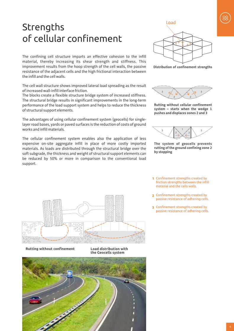
SOIL FILLED (GRASS) CHANNEL PROTECTION SYSTEM
geocells
non-woven geotextileanchor stake with a hook
high strength polyester tendons
geocell protection systemwith topsoil infill and seeded
Concrete protectionAfter filling with concrete the geocells act like a flexible slab and stable expansion joints. The geocells bend and adapt to the minor subgrade movements, reducing cracking of the concrete. The cellular confinement system is ideal for protection of channels exposed to severe erosive conditions, as well as channels with continuous flows.
Benefits of geocells subgrade drainage requirements and the deformation potential within the structure can also be addressed, the system can be designed for a particular site based upon compatibility with local environmental, ecological and aesthetic requirements, enables the construction of concrete slab as channel reinforcement, confines infill material, improving their properties.
Typical applications storm water diversion and containments process water channels drainage ditches intermittent or continuous flow channels flood banks storm water containments fire protection containments channels at sports facilities
13
Geocells ditch protection systemsee general guidelines forselection of infill materials
DITCH PROTECTION SYSTEM
native soil
TENDONS WHERE REQUIRED BY DESIGN
water level
non-woven geotextileanchors
CONCRETE FILLED CHANNEL PROTECTION SYSTEM
Geocells channel protection systemwith topsoil infill and seededabove normal water level
-
water level
Geocells channel protectionsystem with concrete infill belownormal water level
-
native soil
non-woven geotextileanchors
Constant flow channels
SOIL FILLED (GRASS) CHANNEL PROTECTION SYSTEM
Geocells channel protection systemwith topsoil infill and seeded
water level
native soil
tendons where required by design
non-woven geotextile
anchors
Intermittent flow channels
14

SOIL FILLED (GRASS) CHANNEL PROTECTION SYSTEM
geocells
non-woven geotextileanchor stake with a hook
high strength polyester tendons
geocell protection systemwith topsoil infill and seeded
Concrete protectionAfter filling with concrete the geocells act like a flexible slab and stable expansion joints. The geocells bend and adapt to the minor subgrade movements, reducing cracking of the concrete. The cellular confinement system is ideal for protection of channels exposed to severe erosive conditions, as well as channels with continuous flows.
Benefits of geocells subgrade drainage requirements and the deformation potential within the structure can also be addressed, the system can be designed for a particular site based upon compatibility with local environmental, ecological and aesthetic requirements, enables the construction of concrete slab as channel reinforcement, confines infill material, improving their properties.
Typical applications storm water diversion and containments process water channels drainage ditches intermittent or continuous flow channels flood banks storm water containments fire protection containments channels at sports facilities
13
Geocells ditch protection systemsee general guidelines forselection of infill materials
DITCH PROTECTION SYSTEM
native soil
TENDONS WHERE REQUIRED BY DESIGN
water level
non-woven geotextileanchors
CONCRETE FILLED CHANNEL PROTECTION SYSTEM
Geocells channel protection systemwith topsoil infill and seededabove normal water level
-
water level
Geocells channel protectionsystem with concrete infill belownormal water level
-
native soil
non-woven geotextileanchors
Constant flow channels
SOIL FILLED (GRASS) CHANNEL PROTECTION SYSTEM
Geocells channel protection systemwith topsoil infill and seeded
water level
native soil
tendons where required by design
non-woven geotextile
anchors
Intermittent flow channels
14

Erosion control
/ Slope protection
In case of single-layer cover materials of earth slopes and embankments the walls of the cells confine the topsoil creating a series of mini dams controlling downslope movement of the infill through increasing its resistance to storm water runo� while creating a natural environment for vegetation. This can result in resistant and durable protective covers even in case of steep earth slopes and embankments.
The earth retention systems (retaining walls) produced with our technology perform the same functions as the conventional earth retention structures and can cost-e�ectively replace the conventional solutions while meeting all site challenges and shortening the installation time.
Vegetated slopesThe geosystem confines and reinforces topsoil and vegetation. The cells increase the resistance to erosive forces, protecting the root zone from loss of soil particles. The system works particularly well on steep slopes and in areas of low-to-moderate flows.
Aggregate slopesThe geosystem improves the erosive resistance of granular materials. The hydraulic energy dissipates and single soil particles do not move downwards as they are protected against gravity forces and exposure to concentrated hydraulic flow.
perforated Geocells sectionwith topsoil, stone or concreteinfil as required by design
PARTIAL ISOMETRIC CHANNEL SYSTEM
non-woven geotextilebetween founation soiland Geocells as required
finished slope
EROSION CONTROL / SLOPE PROTECTION
15
Everything Tailor Made
SOIL FILLED (GRASS) CHANNEL PROTECTION SYSTEM
Concrete-armored slopesThanks to geocell sections it is no longer necessary to use costly, complex structural elements requiring long-term preparation. After filling with concrete the geocells act like a flexible slab and stable expansion joints. The geocells bend and adapt to the minor subgrade movements, reducing cracking of the concrete.
Cellular confinement sections with large cellsCellular confinement sections with large cells wrap and protect the root area of vegetation layer. It is easy to planting shrubs and small trees inside the cells. Large cells are ideal for moderate vegetated slopes with minimal hydraulic flow.
Benefits of geocells with concrete infilling the systems becomes a flexible concrete mat with integrated expansion structure, e�ectively protects slopes and support the structure filled with granular materials (sand, gravel and other mineral materials), fast installation of slope reinforcement and structure durability, minimizing the need to use heavy duty equipment
geocells
non-woven geotextileanchor stake with a hook
high strength polyester tendonsgeocell protection systemwith topsoil infill and seeded
16

Retaining walls
The multi-layered geocells become an ideal solution for retaining walls,
while fulfilling all structural design requirements.Geocell earth retention system offers desirable aesthetics and
environmental benefits from a naturally-vegetated, near
vertical fascia with the same structural stability found in
conventional retaining wall systems.
Geocells allow for construction flexibility, meeting site
challenges when subgrade soils are compressible or
construction is in difficult-to-access locations.
Retaining wallsThe multi-layered confinement system is used for a wide range of earth
retention design requirements. The conventional stability methods may be
used in for system; also computer programmes are available for a broad
range of parameters including subgrade, embankment and loads.The fascia of the retaining walls may be covered with various finishes
including topsoil with various selected vegetation. Simple, effective
construction techniques make the system ideal for installations in remote
or restricted-access sites.
Gravity wall structuresThe cellular confinement system confines and reinforces the granular layer
forming a bulk structure. The structure distributes the lateral forces of the
ground and is a load bearing structure thanks to high frictional interaction
between the layers. Possible subsoil deflections do not affect the loss ofload bearing capacity. Geocells may support various finishes of fascia or
may be covered with natural vegetation topsoil.
Geocomposite retaining wallsCellular confinement system helps to eliminate the need for more costly,
complicated structural elements. The system combines into covered fascia
walls which can be integrated with the slope through various anchoring
solutions. The outer cells may be filled with topsoil in order to sustain the
natural layer of vegetation.
Rock face protection – stacked geocells fasciaFascia protection for steepened slopes. Geocells create a layered wall structure without requirements for additional earth reinforcement when simple fascia protection is required over a structurally-stable soil embankment.
It is characteristic for the geocells that the
system is a very economical and much
cheaper than conventional solutions and do
not require a deep foundation.
200 mm
rock face
clear stone
perforated drainage pipewrapped in Geotextile
bedrock
geocells stackedfacia
RETAINING WALLS
18
Everything Tailor Made
TYPICAL STAKE/TENDON CREST ANCHOR SYSTEM
Stake and crest anchorage
Anchor tied to tendon
Anchor trench
Earth anchor
earth anchor
clip engaged to tendon withclove hitch or moore hitch knotand bearing against cell wall
anchor hooked over cell wall
anchor, J–pin or wood stake
clip engaged to tendon withclove hitch or moore hitch knotand bearing against cell wall
Deadman anchor
stake anchor bearingagainst cell wall
deadman anchors orcontinuous
pipe
Typical applications steep shoreline and slopes, protection of slopes and bridge and viaduct abutments, protection of earth slopes and covering of waste disposal areas, protection of geomembrane, earth retention walls in shoreline, corrosion protection of flood banks, motorway embankments,
BEFORE
AFTER
17

stacked perforated geocellswall sections outer cells withtopsoil infill & vegetated
granular infill
perforated drainage pipe wrapped in Geotextile
stacked perforated geocellswall sections outer cells withtopsoil infill & vegetated
200 mm
perforated drainage pipewrapped in Geotextile
geosynthetic reinforcement
granular infill
non-woven geotextile
REINFORCED SLOPE – STACKED GEOCELLS FACIA
Geocomposite retaining wallsGeocomposite retaining walls where wall facing sections are integrated with geosynthetic earth reinforcement layers The construction is based on geocomposite materials where wall facing sections are integrated with geosynthetic earth reinforcement layers. This solution uses many combines features in order to increase the structural stability. The most common elements include geotextiles, geogrids, anchors, etc.
Gravity Wall StructureThe geocell gravity wall system is used when space constraints do not allow the use of earth reinforcement materials. The system is constructed as a layered gravity wall structure that resists lateral pressures and maintains structural integrity even when significant subgrade deformations occur.
stacked perforated geocellswall sections outer cells withtopsoil infill & vegetated
granular or concretelevelling pad
200 mm
non-woven geotextile
geosynthetic reinforcement
granular infill
topsoil or soil cover
perforated drainage pipewrapped in Geotextile
19
Benefits for the environmentThe multi-layered geocell system features horizontal terraces with exposed outer facia cells, creating a natural
environment for selected sustainable vegetation. The vegetated system allows rain water to fall on the exposed
horizontal soil terrace, maximizing water collection, and minimizing runoff.Evaporation of topsoil moisture is controlled through the impervious vertical wall structure creating an
environment for healthy vegetation. By maintaining a near vertical profile the system limits site disruption and
reduces valuable land use.
Wall selection criteriaThe earth retention system can be designed in a variety of wall configurations to meet specific site and
reinforcement requirements. Selection of the wall type is influenced by the project site soil conditions, space
accessibility or restrictions, availability of suitable backfill materials, project economics and the desired aesthetics
of the completed site.
Benefits The system is an accepted retaining wall system for fill or embankment support, Classical methods of stability analysis can be applied for a broad range of infill, backfill, ground water and
surcharge parameters, Simple, effective construction techniques make the system ideal for installations in remote or restricted access sites.
Multi-Layered Channel SystemGeocell sections layered along channel side slopes with vegetative infill offer a natural appearance, stability and protection to channels exposed to erosive conditions of water.
This multi-layered configuration can tolerate differential settlement without loss of system integrityand provides a near-vertical profile, reducing valuable land use.
When applied in areas of anticipated high-energy water impact, the geocell sections can be wrappedwith coir fabric to reduce the potential for soil loss in the outer face while vegetation is being established or infilled with large aggregate or concrete grout.
Benefits of geocells Maintains structural stability against known
externally imposed loads, Adapts to a wide range of design requirements
and site conditions, Will not corrode or degrade as concrete, steel and
timber-based systems, Allows use of aggregate to minimize hydrostatic
conditions, Easy to transport and construct at difficult or
remote locations, Allows use in higher velocity-flow channel
applications with large aggregate or concrete infill in
outer cells, Offers aesthetics and environmental benefits of
a sustainable living wall structure with desiredvegetation and plantings.
Typical applicationsThe multi-layered design makes the system very
adaptable to specific retaining wall application
requirements and wall types. fascia protection for steepened slopes, geocomposite retaining walls where wall facing
sections, are integrated with geosynthetic earth
reinforcement layers, gravity wall structure where space accessibility or
restrictions are a problem, multi-layered channel protection structure, retaining walls in landscape design, bioengineered walls, steepened embankments, dike and levee protection, culvert headwalls, vegetated channel structures, sound barriers.
20
200 mm

stacked perforated geocellswall sections outer cells withtopsoil infill & vegetated
granular infill
perforated drainage pipe wrapped in Geotextile
stacked perforated geocellswall sections outer cells withtopsoil infill & vegetated
200 mm
perforated drainage pipewrapped in Geotextile
geosynthetic reinforcement
granular infill
non-woven geotextile
REINFORCED SLOPE – STACKED GEOCELLS FACIA
Geocomposite retaining wallsGeocomposite retaining walls where wall facing sections are integrated with geosynthetic earth reinforcement layers The construction is based on geocomposite materials where wall facing sections are integrated with geosynthetic earth reinforcement layers. This solution uses many combines features in order to increase the structural stability. The most common elements include geotextiles, geogrids, anchors, etc.
Gravity Wall StructureThe geocell gravity wall system is used when space constraints do not allow the use of earth reinforcement materials. The system is constructed as a layered gravity wall structure that resists lateral pressures and maintains structural integrity even when significant subgrade deformations occur.
stacked perforated geocellswall sections outer cells withtopsoil infill & vegetated
granular or concretelevelling pad
200 mm
non-woven geotextile
geosynthetic reinforcement
granular infill
topsoil or soil cover
perforated drainage pipewrapped in Geotextile
19
Benefits for the environmentThe multi-layered geocell system features horizontal terraces with exposed outer facia cells, creating a natural
environment for selected sustainable vegetation. The vegetated system allows rain water to fall on the exposed
horizontal soil terrace, maximizing water collection, and minimizing runoff.Evaporation of topsoil moisture is controlled through the impervious vertical wall structure creating an
environment for healthy vegetation. By maintaining a near vertical profile the system limits site disruption and
reduces valuable land use.
Wall selection criteriaThe earth retention system can be designed in a variety of wall configurations to meet specific site and
reinforcement requirements. Selection of the wall type is influenced by the project site soil conditions, space
accessibility or restrictions, availability of suitable backfill materials, project economics and the desired aesthetics
of the completed site.
Benefits The system is an accepted retaining wall system for fill or embankment support, Classical methods of stability analysis can be applied for a broad range of infill, backfill, ground water and
surcharge parameters, Simple, effective construction techniques make the system ideal for installations in remote or restricted access sites.
Multi-Layered Channel SystemGeocell sections layered along channel side slopes with vegetative infill offer a natural appearance, stability and protection to channels exposed to erosive conditions of water.
This multi-layered configuration can tolerate differential settlement without loss of system integrityand provides a near-vertical profile, reducing valuable land use.
When applied in areas of anticipated high-energy water impact, the geocell sections can be wrappedwith coir fabric to reduce the potential for soil loss in the outer face while vegetation is being established or infilled with large aggregate or concrete grout.
Benefits of geocells Maintains structural stability against known
externally imposed loads, Adapts to a wide range of design requirements
and site conditions, Will not corrode or degrade as concrete, steel and
timber-based systems, Allows use of aggregate to minimize hydrostatic
conditions, Easy to transport and construct at difficult or
remote locations, Allows use in higher velocity-flow channel
applications with large aggregate or concrete infill in
outer cells, Offers aesthetics and environmental benefits of
a sustainable living wall structure with desiredvegetation and plantings.
Typical applicationsThe multi-layered design makes the system very
adaptable to specific retaining wall application
requirements and wall types. fascia protection for steepened slopes, geocomposite retaining walls where wall facing
sections, are integrated with geosynthetic earth
reinforcement layers, gravity wall structure where space accessibility or
restrictions are a problem, multi-layered channel protection structure, retaining walls in landscape design, bioengineered walls, steepened embankments, dike and levee protection, culvert headwalls, vegetated channel structures, sound barriers.
20
200 mm
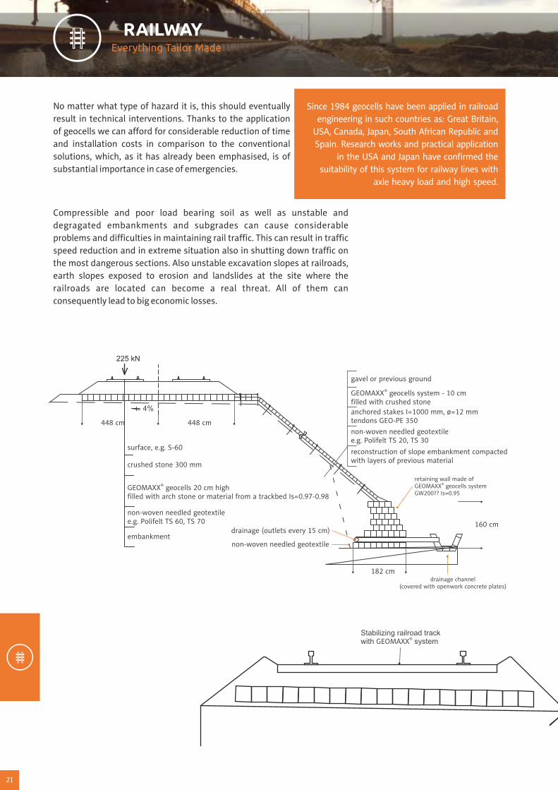
No matter what type of hazard it is, this should eventually result in technical interventions. Thanks to the application of geocells we can a�ord for considerable reduction of time and installation costs in comparison to the conventional solutions, which, as it has already been emphasised, is of substantial importance in case of emergencies.
Compressible and poor load bearing soil as well as unstable and degragated embankments and subgrades can cause considerable problems and di�culties in maintaining rail tra�c. This can result in tra�c speed reduction and in extreme situation also in shutting down tra�c on the most dangerous sections. Also unstable excavation slopes at railroads, earth slopes exposed to erosion and landslides at the site where the railroads are located can become a real threat. All of them can consequently lead to big economic losses.
Since 1984 geocells have been applied in railroad engineering in such countries as: Great Britain,
USA, Canada, Japan, South African Republic and Spain. Research works and practical application
in the USA and Japan have confirmed the suitability of this system for railway lines with
axle heavy load and high speed.
RAILWAY
21
Previous experience in solving the geotechnical problems related to repairs,
modernization and construction of railway lines have confirmed the possibility and
technical and economic purposefulness of use of cellular confinement systems in
several typical applications.
Thanks to the technology based on the application of GEOMAXX® geocells system we can provide technical and economic solutions to the following problems:
stabilization and support of the substructure of rail tracks on the soft and flexible soil (including during the application of sleepers, pre-tension prestressed concrete switch sleepers and jointless rail tracks), construction of stable and long-life road and rail crossing, liquidation of wet-beds, repeated used of breakstone during the repairs of railway subgrades, limitation of deep soil replacement, reduction of the propagation of oscillation and vertical and horizontal vibration from railway subgrades (protection of historic buildings), prevention of the occurrence of stray currents and extending the life of rails and crossovers, enabling the construction of stable and long-life connections of subgrades to bridges and viaducts, enabling the application of any type of surfaces along and inside the railway subgrade that remain environmentally beneficial while taking care of the aesthetic landscape design, enabling quick repairs and modernization of stable road and rail crossings on poor subsoil, enabling a significantly faster modernization or repair of subgrade, frequently with tra�c continued on the neighbouring track, stabilization and corrosion protection of earth slopes, excavation slopes and embankments, possibility to form embankments on poor load bearing soils, possibility to form earth retention walls and soil sound absorbing structures.
22
Everything Tailor Made
225 kN
4%
448 cm 448 cm
182 cm
160 cm
® STABILIZING THE TRACKWAY WITH GEOMAXX SYSTEMWITH DITCH PROTECTION AND EROTION COTROL FOR SLOPES
Non-woven geotextile
Anchors
Tendons
®GEOMAXX slope protection system(with topsoil infill and seeded)
®GEOMAXX ditch buildwith concrete infill
Stabilizing railroad track®with GEOMAXX system
gavel or previous ground®GEOMAXX geocells system - 10 cm
filled with crushed stoneanchored stakes I=1000 mm, ø=12 mmtendons GEO-PE 350non-woven needled geotextilee.g. Polifelt TS 20, TS 30
reconstruction of slope embankment compactedwith layers of previous material
retaining wall made of®GEOMAXX geocells system
GW200?? Is=0.95
surface, e.g. S-60
crushed stone 300 mm
®GEOMAXX geocells 20 cm highfilled with arch stone or material from a trackbed Is=0.97-0.98
non-woven needled geotextilee.g. Polifelt TS 60, TS 70
embankmentdrainage (outlets every 15 cm)
non-woven needled geotextile
drainage channel(covered with openwork concrete plates)
21
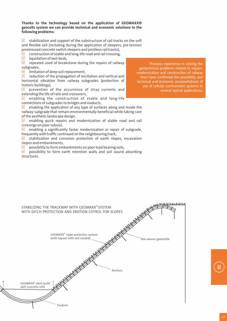

23
Constructing airports and infrastructure for civil and military aviation with geocells
More than 25 years of practice have shown that GEOMAXX® geocells, especially when dealing with weak or unstable soils, are a justified technical and economical alternative for building (among others): airstrips (conventional pavement foundation or directly as turf and soil surfaces), runaway borders, de-icing pads, back stops, dikes at airfields, reservoirs for leachate after cleaning airfield surfaces, foundation and safety tubs for fuel tanks, airfield damage repair, foundation and soil platforms for special devices (for example – free standing constructions of reinforced soil for radar stations).
Typical cross-section for airstrip turf or soil surface construction.
AIRPORTS
24
Everything Tailor Made
®GEOMAXX
AIRSTRIP SHOULDER REINFORCED WITH GEOCELLS
WEAK SOIL OF AIRSTRIP SHOULDER
Turf soil surface
®GEOMAXX sectionswith sand/soil mixture infill (70% / 30%)
Granular subfoundation
Geotextile
Soil foundation
STABILIZING A TRACK-WAY WITH GEOMAXX SYSTEM®
Top view
Drainage ditch
3,20 m
2,60 m
Drainage
Foundation and GEOMAXX infill:®
crushed stone,diameter of grain 20 mm
Subsoil (crushed stonewith min. thickness 200 mm below the tie)
Sections of GEOMAXX type GWS330150TPC®
or GWS330200TPCLength when streched - 4,20 m
(perpendicular stretch to the rail axis)
TYPICALCROSS-SECTION
Properly formednative soil
Sections GEOMAXX type GWS330150TPC®
or GWS330200TPC(depending on the ground durability)
Sections GEOMAXX®
type GWS330200TPC2,44 m width when spread
®Installing the systemGEOMAXXin a trackbed in Ptaszkowa

Deicing aircraft platforms - engineering and ecological problemHaving in mind the program of modernizing and building national airports (Warsaw, Gdansk, Poznan) building deicing aircraft platforms is one of the airport infrastructure elements required for the given airport class in the certain climatic conditions. The research carried in the USA by FAA (Federal Aviation Administration) have shown, that even a layer of ice on the aircraft's wings as thin as 0,4 mm reduces the ability of raising up by 12% - 24%. For safety reasons it is forbidden to allow any ice-covered aircraft to set o�.
Besides the factors of the air tra�c, there is also an important issue of protecting the soil-water environment from pollution. It is an important issue, because the surfaces of such platforms for international airports can cover areas of 6-12 ha (equivalent to approx. 7 -11 football pitches).
Deicing of an aircraft is usually being carried with a use of liquids, a mixture of ethylene glycol (60%) water (40%) or propylene glycol with lower freezing point. Covering an aircraft with such mixture protects against repeated freezing for approx. 70 minutes. At high humidity, in certain winter conditions, 700-4500 liters of the liquid is used, while in case of harder conditions it takes even up to 18 000 liters. Some part of the liquid flows down onto the apron and the rest of it is being removed during the takeo�. If the start of an airplane is getting delayed, the whole process is being repeated. Liquids used for deicing are toxic and should not stay on the apron, aggravating the storm water drainage.
This complexity of the problem results from the fact, that deicing platforms require a proper drainage system, regenerating and cleansing the e�uents, ensured soil isolation from pollution and the foundation of the platform needs to protect the whole structure against irregular subsidence of the ground. In case of weak, compressible and heterogeneous soils it is often associated with deep soil exchange. Taking into account a surface of such platform, which needs to serve for few up to over a dozen airplanes we have to deal with huge financial outlays.
1091,5
203
7,5
310
170
401
concrete surface (based on Portland cement thickness of approx. 400 mm)
asphalt concrete layer (thickness approx. 170 mm)
PP needled nonwoven geotextiles
HDPE geomembrane (1.5 mm)
foundation with crushed concrete
GEOMAXX® geocells of 20mm height, filled with compacted aggregate to Is> 0.98
PP needled nonwoven geotextiles
PP needled nonwoven geotextiles
Example cross-section of the platform for deicing of aircrafts
25 26
CertificatesOur company and our products our recognizably certified:
ISO 9001
ISO 14001
Technical Approval
Factory Production Control Certificate
Higienic Certificate
Certificate of Conformity (Railway Institute)
All certificates are regularly renewed.
AchievementsOur achievements were honored with many awards, among others for:
Product development
Innovativeness
Finance
Export and Sales
The Geo Globe Polska is constantly looking for new innovative solutions.
Unique performance What makes Geo Globe Polska stand out from its competitors is both quality and a comprehensive range of provided
services. We take greatest care of every detail at each stage of work. Our production involves the highest technology.
We have electronic data flow of documentation and ERP management system in use. Thanks to our professionally
equipped laboratory our products undergo a thorough testing before they reach our Client.
Our team – professionals and enthusiasts There is more than a hundred qualified specialists in Geo Globe Polska, among them a lot of employees with life
experience in plastic processing industry.
Certified qualityIn Geo Globe Polska we opt for quality. In 2005 we implemented and certified an integrated environment and quality
management system that conforms to ISO 9001 and ISO 14001 standards. Our products hold many approvals and
certifications. We are also very proud of our cooperation with Barbara Experimental Mine in Mikołów, Central Mining
Institute in Katowice, Building Technical Institute and Road and Bridge Research Institute.
Awards For the three consecutive years our company has been awarded Gazela Biznesu, a prestigious award for the most
dynamically developing companies. In 2008 Geo Globe Polska was among the laureates of the 18th edition of Teraz
Polska contest for the production of cellular confinement system, winning the highest assessment scores in analyses
carried out by a panel of experts in the category of Best Products. Dun and Brand Street Poland together with its partner
Getin Bank granted to Geo Globe Polska the Certificate of Transparent Enterprise. Being awarded is an expression of
financial reliability and honesty; it also boosts our prestige and competitiveness on the market. We have also been
exceptionally honoured during the 6th Gala Event of the Polish Nationwide Ranking Export Leaders.

Who we are?On the market since 1993
Geo Globe Polska (formerly Kruk i Fischer) was established in 1993 as a joint venture enterprise with a German
partner Dr K.G. Fischer. In response to the vast market potential we are still developing and enlarging the range of
our services. Our leading technology then was vacuum thermoforming of plastics such as: ABS, PE, PS, PP, PMMA,
which involves heating plastic to a point of plasticity before it is injected by ram pressure into the closed mold
cavity. After several years – as a result of reorganization – Kruk i Fischer became a family-owned business with all the
capital being owned by the members of the Kruk family. A step forward in the history of Kruk i Fischer was the
purchasing of MIPLAST Sp. z o.o. – former Nitron S.A. Scientific Research Centre with its registered seat in Mikołów
in the year of 2003. In the years to follow the Enterprise has been earning reputation of a leader on the plastic
industry market. Then the market launch of GEOMAXX® geocells in 2005 – our flagship product – following a two-
year testing in our company labs, became the boosting success. In 2008 we received an EU grant support from the
European Regional Development Fund following the Sectoral Operational Programme Improvement of the
Competitiveness of Enterprises, years 2004–2006 for our project called Innovative Technology of Geocells of
Various Resistances and Temperature Resistance.
Another grant from the EU funds from the European Fundation of Regional
Development the Regional Operational Programme of the Silesia
Voivodeship (ROP SV) for years 2007-2013 for the project called:
"Innovative technology for production of sheets and film production
based on obtained granulate" allowed us to extend our possibilities.
Clear cut development strategyWe can say that it is the existence of our two strengths that makes us a strong and dynamically developing
enterprise. We are aiming to develop strategy based on solid information, to win advantage on the competitive
market and to create efficient, customer-oriented and cost-effective enterprise. Our mission is a broader
development on the European markets while keeping a strong position of a leader on our domestic market in
Poland.
Everything tailor-madeOur aim is the delivery of tailor-made services. Fast and efficient sales require an individual approach to consumer
preference!
On October 1st, 2008 the enterprise was transformed from a limited liability company into a limited
joint-stock partnership, changing alsoits business name
into Geo Globe Polska.
Geo Globe Polska Spółka z ograniczoną odpowiedzialnością
Spółka komandytowa
43-190 Mikołówul. Dzieńdziela 30
tel. +48 32 226 07 96 +34606 35 47 87fax +48 32 226 05 [email protected]@geomaxx.eswww.geoglobe.pl,www.geomaxx.es
www.geoglobe.pl
Everything Tailor Made
GEOCELLS