Embed Size (px)
Citation preview

www.white-rodgers.com00
RE
LA
YS
an
dT
RA
NS
FO
RM
ER
S
RELAYS and
TRANSFORMERS INDEX
WHITE-RODGERS CONTACTORS 108 – 111 Model(s) Description Page(s)
CONTACTORS: 1 Pole .............................................................. Definite Purpose ................................................................................................ 08 2 Pole .............................................................. Definite Purpose ................................................................................................ 09 3 Pole .............................................................. Definite Purpose ................................................................................................ 0-
WHITE-RODGERS RELAYS 112 – 117 Model(s) Description Page(s)
Potential Relays ............................................................................................................................................................................ 2 Potential Relays ............................................. Cross Reference ................................................................................................ 3 Enclosed Relays Enclosed Fan Relays ...................................................................................................................................... 4 Enclosed Heavy Duty Relays Enclosed Fan Relays ................................................................................................................. 5 Switching Relays .......................................................................................................................................................................... 6-7
DC POWER (SOLENOIDS) CONTACTORS 118 – 120 Model(s) Description Page(s)
Type 70 / 120 .................................................. Single Pole Normally Open ............................................................................... 9 Type 124 / 586 ................................................ Single Pole Normally Open/Single Pole Double Throw ..................................... 20
CLASS 2 TRANSFORMERS AND FAN CONTROL CENTERS 101 – 105 Model(s) Description Page(s)
Class 2 Transformers .................................... Replacement Guide ........................................................................................... 0 90-T / T40 / 5400 / S80 / 90 Series ................. Class 2 Transformers/Fan Control Centers/2 Pole Switching Relays ............... 02-05
AIR CONDITIONING 106 – 107 Model(s) Description Page(s)
Pullout Disconnects ...................................... Cutler Hammer .................................................................................................. 06-07

www.white-rodgers.com 0
RE
LA
YS
an
dT
RA
NS
RO
RM
ER
S
Model Suggested Model Suggested Model SuggestedNumber Replacement Number Replacement Number Replacement
3TZ66 90-T40M 90-403F 90-T40F3 AT72D96 90-T40M23TZ67 90-T40F3 90-503F 90-T50F3 AT72D204 90-T40M3TZ68 90-T40M3 90-604C 90-T60C3 AT72D246 90-T40M3TZ69 90-T60C3 90-754C 90-T75C3 AT72D683 90-T40M3TZ70 90-T75C3 90-T00C 90-T00C AT72D69 90-T40M240F 90-T40F 90-T40F 90-T40F AT87A007 90-T50M3402F 90-T40F2 90-T40F2 90-T40F2 AT87A049 90-T50F3403F 90-T40F3 90-T40F3 90-T40F3 AT87A056 90-T50F34A420L 90-T40M 90-T40M 90-T40M AT87A06 90-T50M34A424L 90-T40M3 90-T40M2 90-T40M2 AT88A005 90-T75C34B420L 90-T40M 90-T40M3 90-T40M3 AT88A02 90-T75C34B42L 90-T40M2 90-T50C3 90-T50C3 BTR-403 90-T40M4E420L 90-T40F 90-T50F3 90-T50F3 BTR-405 90-T40F4E42L 90-T40F2 90-T50M3 90-T50M3 BTR-406 90-T40F25030 90-T40M3 90-T60C3 90-T60C3 BTR-482 90-T40F350302 90-T40M 90-T75C3 90-T75C3 GT-443 90-T40M350303 90-T40M2 AT20A004 90-T40M3 GT-444 90-T40F50304 90-T40M3 AT40A000 90-T40M GT-446 90-T40F35034 90-T50M3 AT40A08 90-T40M3 S8-30 90-T40M5036 90-T60C3 AT40A026 90-T40M2 S8-220 90-T40M503F 90-T50F3 AT40B032 90-T40F2 S8-280 90-T40M5032 90-T75C3 AT40B206 90-T40F S8-38 90-T40M50327 90-T50C3 AT40B24 90-T40F3 S8-330 90-T40M50352 90-T40F AT40B388 90-T40F2 S8-373 90-T40F50353 90-T40F2 AT50A007 90-T50M3 S8-374 90-T40S250354 90-T40F3 AT50B46 90-T50M3 S8-407 90-T40M504C 90-T50C3 AT50B237 90-T50F3 S8-424 90-T40M604C 90-T60C3 AT75A008 90-T75C3 S8-427 90-T40M620-205 90-T40F AT20A23 90-T40F3 S8-442 90-T40M620-206 90-T40F2 AT40A2 90-T40F3 S8-484 90-T40M620-402 90-T40M3 AT40A39 90-T40F3 S84A-89 90-T40F620-403 90-T40M3 AT72D006 90-T40M S84G- 90-T40M620-404 90-T40M3 AT72D04 90-T40M2 S84G-73 90-T40M620-405 90-T40F AT72D022 90-T40M2 Y65AJ- 90-T40M620-406 90-T40F2 AT72D048 90-T40M Y65AP- 90-T40M3620-482 90-T40F3 AT72D055 90-T40M2 Y65AR- 90-T40M620-502 90-T50M3 AT72D063 90-T40M2 Y65AS- 90-T40F620-752 90-T75C3 AT72D089 90-T40F Y65BR- 90-T40M3754C 90-T75C3 AT72D05 90-T40F2 Y65BS- 90-T40F290-40F 90-T40F AT72D88 90-T40M Y65SR- 90-T40M390-402F 90-T40F2
CLASS 2 TRANSFORMERREPLACEMENT GUIDE

www.white-rodgers.com02
RE
LA
YS
an
dT
RA
NS
FO
RM
ER
S
CLASS 2TRANSFORMERS
Model Mars Jard Number Part No. Part No. VA Hz Primary Connections Sec. Connections 90-T40M1 50302 40M 40 60 20V Leads 24V Leads 90-T40M2 50303 402M 40 50/60 208/240V Leads 24V Leads 90-T40M3 50304 403M 40 60 20/208/240V Leads 24V Leads 90-T50M3 5034 503M 50 60 20/208/240V Leads 24V Leads
MULTI-MOUNT (CLOSED CONSTRUCTION) UNIVERSAL MOUNTING WITH PLATE
90-T40S1 THRU 90-T75C3 24 VOLT SECONDARYCLASS 2 TRANSFORMERS ENERGY LIMITINGFor Industrial, Heating and Air Conditioning Controls Applications
SPECIFICATIONSAgency . . . . . . . . . . . . . . . . . . . . . . . . . . . U.L. file number E33334
FEATURES• Color coded primary leads.• Multi-mount styles available.
90-T40F1
Model Mars Jard Number Part No. Part No. VA Hz Primary Connections Sec. Connections 90-T40F1 50352 40F 40 60 20V Leads 24V Leads 90-T40F2 50353 402F 40 50/60 208/240V Leads 24V Leads 90-T40F3 50354 403F 40 60 20/208/240V Leads 24V Leads T40-24 – – 40 50/60 20/208/240V Leads 24V Leads 90-T50F3 – 503F 50 60 20/208/240V Leads 24V Leads
FOOT-MOUNT (OPEN CONSTRUCTION)
Model Mars Jard Number Part No. Part No. VA Hz Primary Connections Sec. Connections 90-T50C3 50327 504C 50 50/60 20/208/240V Leads 24V Leads 90-T60C3 50327 604C 60 50/60 20/208/240V Leads 24V Leads 90-T75C3 5032 754C 75 50/60 20/208/240V Leads 24V Leads 90-T100C1 – – 00 60 20V Leads 25V Leads 90-T100C2 – – 00 50/60 208/240V Leads 25V Leads
FOOT-MOUNT (MANUAL RESET, OPEN CONSTRUCTION)
Primary Side Secondary Side Common 120V 208V 240V Common 24V * Black White Red Orange Blue Yellow
TRANSFORMER LEAD COLOR CODING
90-T40S3
90-T75C3
WALL PLUG-INIsolation Step Down TransformerFEATURES• Sealed tamper and impact resistant case.• Output termination is screw terminals.• Non-polarized 20V plug-in blades.• Trouble free maintenance.• Isolated from power source.
SPECIFICATIONSDimensions, 5401A-1 . . . . . . . . . . . . . . 3”H x 2/2”W x 3/4”DDimensions, 5402A-1 . . . . . . . . . . . . . . 3”H x 23/4”W x 2/4”DOutput terminals . . . . . . . . . . . . . . . . . . . #6-32 screwsAgency ratings . . . . . . . . . . . . . . . . . . . . C.S.A. and U.L. class 2
5401A-1 Model Number Primary Secondary
5401A-1 20VAC, 60 Hz, 0.4A 24VAC, 0VA 5402A-1 20VAC, 60 Hz, 0.3A 24VAC, 25VA
NEW!
NEW!
* Black is common with respect to the transformer winding, not the external circuit.

www.white-rodgers.com 03
RE
LA
YS
an
dT
RA
NS
RO
RM
ER
S
CLASS 2 TRANSFORMERS – ENERGY LIMITINGVarious Standard Configurations of Step Down TransformersDesigned to Power 24V AC Control Systems
FEATURES• Energy limiting design, unaffected by momentary short circuit.• Continued short circuit of secondary will cause primary winding to open in to 2 minutes without creating a fire hazard.• Maximum ambient temperature is 50°F.
SPECIFICATIONSAgency . . . . . . . . . . . . . . . . . . . . . . . . . . . U.L. listed
S84Z-401
S84Z-90
S84A-410
Model Primary to Output Terminations Number Secondary Voltages Rating Line Load
S84Z-401 20/208/240v to 25v 60Hz 40 VA 2”leads 2” leads
SkELETON TYPE WITH VERTICAL & HORIZONTAL CHANNEL FRAMES FOR MOUNTING
Model Primary to Output Terminations Number Secondary Voltages Rating Line Load
S84-11 20v to 25v 60Hz 40 VA 0”leads Screw terminals S84Z-90 20/208/240v to 25v 60Hz 40 VA 0”leads Screw terminals
UNIVERSAL MOUNTED TYPES (Plate, Foot or Hub Mount)
Model Primary to Output Terminations Number Secondary Voltages Rating Line Load
S81-125 20v to 25v 60Hz 40 VA 0”leads Screw terminals S84A-410 Same as S8-25 except transformer recessed in plate and U.L. recognized.
PLATE MOUNTED TYPES
Model Primary to Output Terminations Number Secondary Voltages Rating Line Load
S82A-310 20v to 25v 20 VA 0”leads Screw/spade terminals
HUB MOUNT Class 2 Not Wet/Class 3 Wet (C.S.A. Certified and U.L. Listed)
Model Primary to Output Terminations Number Secondary Voltages Rating Line Load
S84A-310 20v to 25v 40 VA 0”leads Screw/spade terminals
UNIVERSAL MOUNTED TYPES (Plate, Foot or Hub Mount) Class 2 Not Wet/Class 3 Wet (C.S.A. Certified and U.L. Listed)
CLASS 2TRANSFORMERS
S84A-310
S82A-310
Indicates Canadian Model Number: call -800-305-6953 to order
www.white-rodgers.com04
RE
LA
YS
an
dT
RA
NS
FO
RM
ER
S
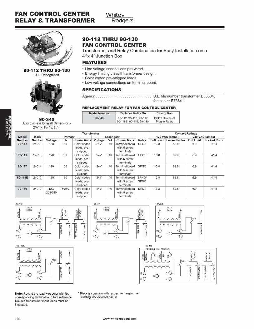
90-112 THRU 90-130FAN CONTROL CENTERTransformer and Relay Combination for Easy Installation on a4”x 4”Junction Box
SPECIFICATIONSAgency . . . . . . . . . . . . . . . . . . . . . . . . . . . U.L. file number transformer E33334, fan center E7364
FEATURES• Line voltage connections pre-wired.• Energy limiting class II transformer design.• Color coded pre-stripped leads.• Low voltage connections on terminal board.
Approximate Overall Dimensions2/8” x 7/8” x 2/4”
FAN CONTROL CENTERRELAY & TRANSFORMER
Transformer Contact Ratings Model Mars Primary Secondary 120 VAC (amps) 240 VAC (amps) Number Number Voltage Hz Connections Voltage VA Connections Relay Full Load Locked Rotor Full Load Locked Rotor 90-112 2400 20 60 Color coded 24V 40 Terminal board DPDT 3.8 82.8 6.9 4.4 leads, pre- with 5 screw stripped terminals 90-113 2403 20 60 Color coded 24V 40 Terminal board SPDT 3.8 82.8 6.9 4.4 leads, pre- with 5 screw stripped terminals 90-117 2404 20 60 Color coded 24V 40 Terminal board SPNO 3.8 82.8 6.9 4.4 leads, pre- with 5 screw stripped terminals 90-118E 2402 20 60 Color coded 24V 40 Terminal board SPNO/ 3.8 82.8 6.9 4.4 leads, pre- with 5 screw SPNC stripped terminals 90-130 2400 20/ 50/60 Color coded 24V 40 Terminal board DPDT 3.8 82.8 6.9 4.4 208/240 leads, pre- with 5 screw stripped terminals
90-112 THRU 90-130U.L. Recognized
Model Number Replaces Relay On Description
90-340 90-2, 90-3, 90-7 DPDT Universal 90-8E, 90-9, 90-30 Plug-in Relay
REPLACEMENT RELAY FOR FAN CONTROL CENTER
BR
OW
N N
.C.
RE
D
BLA
CK
RE
D N
.C.
CO
MM
ON
BLA
CK
C
Y
G
WH
ITE
W
R
CO
M
BLA
CK
N.O
.
COIL
BLA
CK
Y
RE
D N
.O.
VIO
LET
CO
MM
ON
CG
W
COIL
R
BLA
CK
G
BLA
CK
R
RE
D/Y
EL N
.O.
120 V60 HZ
90-112
120 V60 HZ
90-118
G
120 V60 HZ
WH
ITE
R
W
C
208/240 V60 HZ
Y
W
G
WH
ITE
R
W
BLA
CK
CO
MM
ON
BR
OW
N N
.C.
BLA
CK
CO
MM
ON
BR
OW
N N
.C.
RE
D N
.O.
Y
C
COIL
240
RE
D
208
BLU
E
WH
ITE
90-119
Y
BLA
CK
YE
LLOW
N.C
.
COIL
90-113
RE
D N
.O.
120 V60 HZ
BLA
CK
C
RE
D
COIL
90-117
RE
D N
.O.
*
* Black is common with respect to transformer winding, not external circuit.
Note: Record the lead wire color with it'scorresponding terminal for future reference.Unused transformer input leads must beinsulated.
120
WH
ITE
BLA
CK
BR
OW
N N
.C.
BLA
CK
COIL
VIO
LET
CO
MM
ON
YE
LLOW
N.C
.
CO
MM
ON
RE
D/Y
EL N
.O.
240
RE
D
BLU
E
YW
R
RE
D N
.O.
208
120/208/240 V60 HZ
CG
CO
M
90-130
*
90-340
50/60 HZ 50/60 HZ
E
www.white-rodgers.com 05
RE
LA
YS
an
dT
RA
NS
RO
RM
ER
S
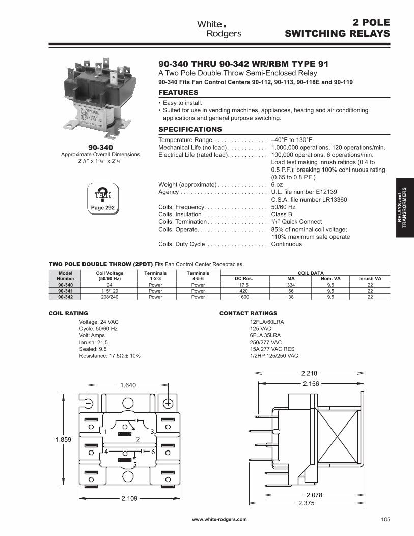
90-340 THRU 90-342 WR/RBM TYPE 91A Two Pole Double Throw Semi-Enclosed Relay90-340 Fits Fan Control Centers 90-112, 90-113, 90-118E and 90-119
SPECIFICATIONSTemperature Range . . . . . . . . . . . . . . . . –40°F to 30°FMechanical Life (no load) . . . . . . . . . . . . ,000,000 operations, 20 operations/min.Electrical Life (rated load). . . . . . . . . . . . 00,000 operations, 6 operations/min. Load test making inrush ratings (0.4 to 0.5 P.F.); breaking 00% continuous rating (0.65 to 0.8 P.F.)Weight (approximate) . . . . . . . . . . . . . . . 6 ozAgency . . . . . . . . . . . . . . . . . . . . . . . . . . U.L. file number E12139 C.S.A. file number LR13360Coils, Frequency. . . . . . . . . . . . . . . . . . . 50/60 HzCoils, Insulation . . . . . . . . . . . . . . . . . . . Class BCoils, Termination . . . . . . . . . . . . . . . . . . /4” Quick ConnectCoils, Operate. . . . . . . . . . . . . . . . . . . . . 85% of nominal coil voltage; 0% maximum safe operateCoils, Duty Cycle . . . . . . . . . . . . . . . . . . Continuous
FEATURES• Easy to install.• Suited for use in vending machines, appliances, heating and air conditioning applications and general purpose switching.
Model Coil Voltage Terminals Terminals COIL DATA Number (50/60 Hz) 1-2-3 4-5-6 DC Res. MA Nom. VA Inrush VA 90-340 24 Power Power 7.5 334 9.5 22 90-341 5/20 Power Power 420 66 9.5 22 90-342 208/240 Power Power 600 38 9.5 22
TWO POLE DOUBLE THROW (2PDT) Fits Fan Control Center Receptacles
Voltage: 24 VAC Cycle: 50/60 Hz Volt: Amps Inrush: 2.5 Sealed: 9.5 Resistance: 7.5Ω ± 0%
COIL RATING
Approximate Overall Dimensions2/8” x 7/8” x 2/4”
2 POLESWITCHING RELAYS
2FLA/60LRA 25 VAC 6FLA 35LRA 250/277 VAC 5A 277 VAC RES /2HP 25/250 VAC
CONTACT RATINGS
6
21
4
3
5
1.640
1.859
2.109 2.0782.375
2.156
2.218
90-340
?Page 292

www.white-rodgers.com06
RE
LA
YS
an
dT
RA
NS
FO
RM
ER
S
?OUTLINE
DRAWINGS300
Maximum Disconnect Type Model Main Amp Wire Size Range Horsepower Rating Number Construction Rating Al/Cu, 60° or 75°C 120 VAC 240 VAC DPU222R Galvanized Steel 60 #4-3 3 0 Non-Fused Pullout ACD222URNM Nonmetallic 60 #4-2 3 0 DPU222RGF ➀ Galvanized Steel 60 #4-3 3 0 DPF221R Galvanized Steel 30 #4-3 /2 3 DPF222R Galvanized Steel 60 #4-3 3 0 ACD221RNM Nonmetallic 30 #4-2 /2 3 ACD222RNM Nonmetallic 60 #4-2 3 0
NOTE Outline drawings, see Tech Help, page 300. Some air conditioning nameplates specify that fused disconnect switches be in-stalled. These specifications must be followed to conform to NEC requirements.
NON-FUSED PULLOUTSThe Industry Standard Pullout when Fuses are not Required
FEATURES• On/Off control provided by a pullout handle.• Pullout handle can be conveniently stored in the compartment in the OFF position, helping to prevent the handle from being misplaced.• Protective shield cannot be removed until the pullout handle is removed, disconnecting the power.
SPECIFICATIONSEnclosure . . . . . . . . . . . . . . . . . . . . . . . . . NEMA 3R outdoor enclosureAgency . . . . . . . . . . . . . . . . . . . . . . . . . . . U.L. listed file no. E5239Symmetrical Interrupting Rating . . . . . . . . 0,000 A Rms
Non-Fused Pullouts
FUSED PULLOUTSUsed when the Air Conditioner Manufacturer RequiresFused Protection
FEATURES• Fuses are installed behind the protective shield that cannot be removed until the pullout handle is removed, disconnecting the power.• Class H fuse clips are provided (fuses not included).• On/Off control provided by a pullout handle.• Pullout handle can be conveniently stored in the compartment in the OFF position, helping to prevent the handle from being misplaced.
SPECIFICATIONSEnclosure . . . . . . . . . . . . . . . . . . . . . . . . . NEMA 3R outdoor enclosureAgency . . . . . . . . . . . . . . . . . . . . . . . . . . . U.L. listed file no. E5239Symmetrical Interrupting Rating . . . . . . . . 0,000 A Rms
Fused Pullouts
Fused Pullout
➀ Includes 20 amp GFI receptacle to meet new NEC code requirements
AIR CONDITIONINGPULLOUT DISCONNECTS CUTLER-HAMMER

www.white-rodgers.com 07
RE
LA
YS
an
dT
RA
NS
RO
RM
ER
S
CUTLER-HAMMERAIR CONDITIONING
PULLOUT DISCONNECTS
MOLDED CASE SWITCHOperates Like a Light Switch...No More Lost Pullout HandlesFEATURES• Rugged molded case construction in a disconnect switch that looks like a circuit breaker but operates like an ordinary household light switch.• Plug-in molded case switch eliminates the need for pullout handles.• No need for replacement pullout handles due to loss or theft.
SPECIFICATIONSEnclosure . . . . . . . . . . . . . . . . . . . . . . . . . NEMA 3R outdoor enclosureAgency . . . . . . . . . . . . . . . . . . . . . . . . . . . U.L. listed file no. E5239Symmetrical Interrupting Rating . . . . . . . . 0,000 A RmsMolded Case Switch
Maximum Model Main Amp Wire Size Range Horsepower Rating Disconnect Type Number Construction Rating Al/Cu, 60° or 75°C 120 VAC 240 VAC Molded Case Switch DPB222R Galvanized Steel 60 #4-3 N/A 0
?OUTLINE
DRAWINGS300

www.white-rodgers.com08
RE
LA
YS
an
dT
RA
NS
FO
RM
ER
S
94-388 THRU 94-396 WR/RBM TYPE 121Straight-Through Wiring, Replaces /2 Pole Devices Used Primarily in Residential Central Air ConditioningFEATURES• Replaces many Type 7 contactors used by OEM’s.• Universal style mounting bracket fits existing mounting holes.• Screw terminals and /4” quick connect terminals for easy installation.SPECIFICATIONSTemperature Range . . . . . . . . . . . . . . . . . –40°F to 50°FMechanical Life (no load) . . . . . . . . . . . . . Conforms to UL and ARI specificationsElectrical Life . . . . . . . . . . . . . . . . . . . . . . Conforms to ARI specifications 94-388 thru 94-390 achieve 200,000 cycles, make LRA at .5 pf, break 25% of FLA at .75 pf at rated voltage, 0,000 cycles make and break LRA at .5 pf rated voltage 94-394 thru 94-396 achieve 00,000 cycles, make LRA at .5 pf, break 25% of FLA at .75 pf at rated voltage, 6,000 cycles make and break LRA at .5 pf rated voltageWeight (approximate) . . . . . . . . . . . . . . . . 7 oz.Agency . . . . . . . . . . . . . . . . . . . . . . . . . . . U.L. file number E75492 C.S.A. file number LR49538Coils Frequency . . . . . . . . . . . . . . . . . . . . 50/60 HzCoil Insulation. . . . . . . . . . . . . . . . . . . . . . Class B (30°C)Termination. . . . . . . . . . . . . . . . . . . . . . . . Screw and Double /4” Q.C.Operate. . . . . . . . . . . . . . . . . . . . . . . . . . . 85% of nominal coil voltage; 0% maximum safe operateDuty Cycle . . . . . . . . . . . . . . . . . . . . . . . . Continuous
Model Number Voltage Res DC Current Nominal Max. Inrush * 30 Amp ** 40 Amp AC OHMS MA VA VA 94-388 94-394 24 6.5 208 5 20 94-389 94-395 20 420 42 5 20 94-390 94-396 208/240 825 2 5 20
Approximate Overall Dimensions3/4” x 2” x 2/2”
COIL DATA
Type Voltage FLA LRA RES 94-388 277 30 50 40 thru 480 30 75 40 94-390 600 30 50 40 94-394 277 40 200 50 thru 480 40 00 50 94-396 600 40 80 50
CONTACT RATINGS
1 POLE DEFINITEPURPOSE CONTACTORS WITH BUS BAR (30A THRU 40A)
2.4452.541
2.313
1.6252.000
.8751.625
.215TYP. 4
40 Amp Model(with cover)
* 30 amp models have no cover on top as in line drawing below** 40 amp models have cover on top as in picture above
30 Amp Model (No Cover)

www.white-rodgers.com 09
RE
LA
YS
an
dT
RA
NS
RO
RM
ER
S
2 POLE DEFINITE PURPOSECONTACTORS (30A THRU 40A)
90-244 THRU 90-249 WR/RBM TYPE 122Designed for Air Conditioning and Heating Equipment
SPECIFICATIONSInsulating Material . . . . . . . . . . . . . . . . . . Contact block and carrier are high quality electrical-grade thermosetting resinTemperature Range . . . . . . . . . . . . . . . . . –40°F to 50°FMechanical Life. . . . . . . . . . . . . . . . . . . . . Conforms to UL and ARI specificationsElectrical Life . . . . . . . . . . . . . . . . . . . . . . Conforms to UL and ARI specificationsWeight (approximate) . . . . . . . . . . . . . . . . 9.5 oz.Agency . . . . . . . . . . . . . . . . . . . . . . . . . . . U.L. file number E75492 C.S.A. file number LR49598Coils Frequency . . . . . . . . . . . . . . . . . . . . 50/60 HzCoil Insulation. . . . . . . . . . . . . . . . . . . . . . Class B (30°C)Termination. . . . . . . . . . . . . . . . . . . . . . . . Pressure Connectors and Double /4” Q.C.Operate. . . . . . . . . . . . . . . . . . . . . . . . . . . 85% of nominal coil voltage; 0% maximum safe operateDuty Cycle . . . . . . . . . . . . . . . . . . . . . . . . Continuous
Model Number Voltage Res DC Current Nominal Max. Inrush * 30 Amp ** 40 Amp AC OHMS MA VA VA 90-244 90-247 24 250 6 32 90-245 90-248 20 224 50 6 32 90-246 90-249 208/240 997 25 6 32
Approximate Overall Dimensions3/4” x 2” x 25/8”
COIL DATA
Type Voltage FLA LRA RES 90-244 277 30 50 40 thru 480 30 75 40 90-246 600 30 50 40 90-247 277 40 200 50 thru 480 40 00 50 90-249 600 40 80 50
CONTACT RATINGS
FEATURES• Low VA coil for cooler operation and increased life.• Quiet operation.• Universal style mounting bracket fits existing mounting holes.• Double break contacts ensure positive make and break.• Screw terminals or pressure connectors and double /4” quick connects provided on all models for easy installation.
2.445
2.610
2.313
1.6252.000
.8751.625
.215TYP. 4
40 Amp Model(with cover)
* 30 amp models have no cover on top as in line drawing below** 40 amp models have cover on top as in picture above
30 Amp Model (No Cover)
www.white-rodgers.com0
RE
LA
YS
an
dT
RA
NS
FO
RM
ER
S
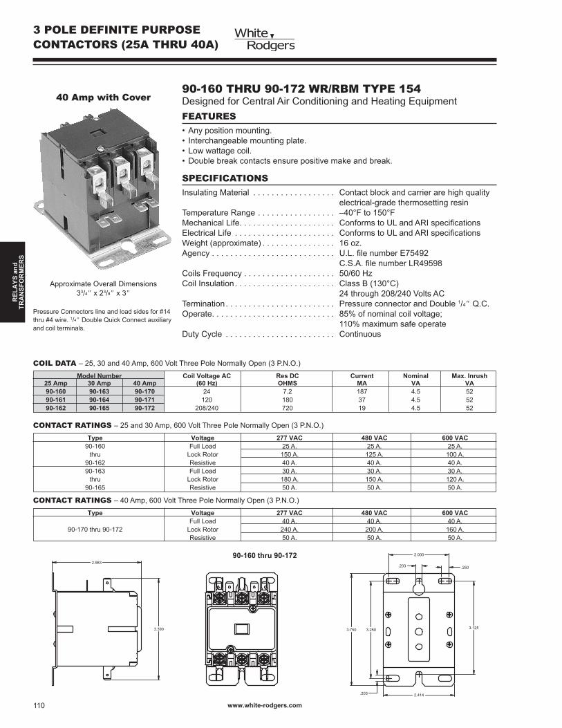
3 POLE DEFINITE PURPOSECONTACTORS (25A THRU 40A)
90-160 THRU 90-172 WR/RBM TYPE 154Designed for Central Air Conditioning and Heating Equipment
SPECIFICATIONSInsulating Material . . . . . . . . . . . . . . . . . . Contact block and carrier are high quality electrical-grade thermosetting resinTemperature Range . . . . . . . . . . . . . . . . . –40°F to 50°FMechanical Life. . . . . . . . . . . . . . . . . . . . . Conforms to UL and ARI specificationsElectrical Life . . . . . . . . . . . . . . . . . . . . . . Conforms to UL and ARI specificationsWeight (approximate) . . . . . . . . . . . . . . . . 6 oz.Agency . . . . . . . . . . . . . . . . . . . . . . . . . . . U.L. file number E75492 C.S.A. file number LR49598Coils Frequency . . . . . . . . . . . . . . . . . . . . 50/60 HzCoil Insulation. . . . . . . . . . . . . . . . . . . . . . Class B (30°C) 24 through 208/240 Volts ACTermination. . . . . . . . . . . . . . . . . . . . . . . . Pressure connector and Double /4” Q.C.Operate. . . . . . . . . . . . . . . . . . . . . . . . . . . 85% of nominal coil voltage; 0% maximum safe operateDuty Cycle . . . . . . . . . . . . . . . . . . . . . . . . Continuous
Model Number Coil Voltage AC Res DC Current Nominal Max. Inrush 25 Amp 30 Amp 40 Amp (60 Hz) OHMS MA VA VA 90-160 90-163 90-170 24 7.2 87 4.5 52 90-161 90-164 90-171 20 80 37 4.5 52 90-162 90-165 90-172 208/240 720 9 4.5 52
Approximate Overall Dimensions33/4” x 23/8” x 3”
COIL DATA – 25, 30 and 40 Amp, 600 Volt Three Pole Normally Open (3 P.N.O.)
Type Voltage 277 VAC 480 VAC 600 VAC 90-60 Full Load 25 A. 25 A. 25 A. thru Lock Rotor 50 A. 25 A. 00 A. 90-62 Resistive 40 A. 40 A. 40 A. 90-63 Full Load 30 A. 30 A. 30 A. thru Lock Rotor 80 A. 50 A. 20 A. 90-65 Resistive 50 A. 50 A. 50 A.
CONTACT RATINGS – 25 and 30 Amp, 600 Volt Three Pole Normally Open (3 P.N.O.)
FEATURES• Any position mounting.• Interchangeable mounting plate.• Low wattage coil.• Double break contacts ensure positive make and break.
40 Amp with Cover
Pressure Connectors line and load sides for #4 thru #4 wire. /4” Double Quick Connect auxiliary and coil terminals.
Type Voltage 277 VAC 480 VAC 600 VAC Full Load 40 A. 40 A. 40 A. 90-70 thru 90-72 Lock Rotor 240 A. 200 A. 60 A. Resistive 50 A. 50 A. 50 A.
CONTACT RATINGS – 40 Amp, 600 Volt Three Pole Normally Open (3 P.N.O.)
2.983
3.390 3.2503.750
.203 .250
2.000
3.125
.203 2.414
90-160 thru 90-172

www.white-rodgers.com
RE
LA
YS
an
dT
RA
NS
RO
RM
ER
S
92-459 THRU 92-4733 POLE HEAVY DUTY CONTACTORS
SPECIFICATIONSCoils, Voltages A.C. . . . . . . . . . . . . . . . . . . . . . 24 through 240Coils, Frequency. . . . . . . . . . . . . . . . . . . . . . . . 50/60 HzCoils, Termination . . . . . . . . . . . . . . . . . . . . . . . Single or Double /4” Q.C.Contacts, Pole Form. . . . . . . . . . . . . . . . . . . . . 3 PNOContacts, Material. . . . . . . . . . . . . . . . . . . . . . . Silver cadmium oxide (50-90 amp)Contacts, Termination. . . . . . . . . . . . . . . . . . . . Box lugs and dual quick connectAgency . . . . . . . . . . . . . . . . . . . . . . . . . . . . . . . U.L. recognized, CSA listed
Induct Resistive Locked @ Line Model Number FLA Per Pole Rotor Voltage 92-459 50 Amp 65 Amp 300 Amp 20v 92-460 50 Amp 65 Amp 300 Amp 240v 92-461 50 Amp 65 Amp 200 Amp 480v 200 Amp 600v
Approximate Overall Dimensions33/4” x 25/8” x 3/2”
(92-459 thru 92-465)
FEATURES• Interchangeable mounting.• Double break contacts.• Box lugs and dual quick connect terminals.
3 POLE CONTACTORS(50A/90A)
Induct Resistive Locked @ Line Model Number FLA Per Pole Rotor Voltage 92-463 60 Amp 75 Amp 360 Amp 20v 92-464 60 Amp 75 Amp 360 Amp 240v 92-465 60 Amp 75 Amp 300 Amp 480v 240 Amp 600v
50 60 Voltage Res. D.C. Current Nominal Max. Inrush Amp. Amp. A.C. OHMS Ma. VA VA
92-459 92-463 24 2.4 580 4 35 92-460 92-464 20 45.5 7 4 35 92-46 90-465 208/240 280 50 4 35
COIL DATA
Contact Ratings
Model Number Voltage FLA LRA RES 92-467 20/240 75 450 93 thru 480 75 375 93 92-469 600 75 300 93 92-471 20/240 90 540 20 thru 480 90 450 20 92-473 600 90 360 20
3.563
4.156
2.750 2.032.217(6 SLOTS)
.438 DIA.
3.750 3.188 3.250
.438.250
.2501.9382.1562.650
4.060
4.730
3.750
.406 DIA.
2.8752.500
3.7504.625
5.000
.190.203 DIA.(4 PLACES)
2.250
2.8752.500
.203 DIA.(6 HOLES)
92-459 thru 92-465
92-467 thru 92-473
75 90 Voltage Res. D.C. Current Nominal Max. Inrush Amp. Amp. A.C. OHMS Ma. VA VA
92-467 92-47 24 0.63 25 27 240 92-468 92-472 20 5.5 225 27 240 92-469 90-473 208/240 63.5 2 27 240

www.white-rodgers.com2
RE
LA
YS
an
dT
RA
NS
FO
RM
ER
S
90-63 THRU 90-71 TYPE 128000UNIVERSAL BRACkETUnmatched Versatility
SPECIFICATIONSTemperature Range . . . . . . . . . . . . . . . . . –40°F to 30°FMechanical Life (no load) . . . . . . . . . . . . . 500,000 operations, 60 operations/minElectrical Life (rated load). . . . . . . . . . . . . Meets U.L. and ARI specificationsOutline Drawings . . . . . . . . . . . . . . . . . . . See page 290Weight (approximate) . . . . . . . . . . . . . . . . 6.5 oz. eachAgency . . . . . . . . . . . . . . . . . . . . . . . . . . . U.L. file number SA1984 C.S.A. file number LR13360Class Insulation . . . . . . . . . . . . . . . . . . . . Class BDuty Cycle . . . . . . . . . . . . . . . . . . . . . . . . Continuous
FEATURES• Replaces thousands of OEM models.• Universal break-off bracket for mounting flexibility.• Guide to replace GE, RBM and other Steveco 90-#s included with each relay.
90-63
POTENTIAL RELAYS
Continuous Drop Model Mars Coil Pick-up Out Coil Data Number Number Voltage Min. Max. Max. DC Res. MA Nom. VA Inrush VA 90-63 9002 70 40 53 65 ,399 29.0 5 0 90-64 9003 395 245 275 40 7,47 2.7 5 0 90-65 9004 336 7 84 90 5,80 5.0 5 0 90-66 9005 395 208 239 30 7,47 2.7 5 0 90-67 9006 420 300 328 2 0,000 2.0 5 0 90-68 9007 495 323 352 35 ,950 0.0 5 0 90-26 9008 395 80 95 00 7,47 2.7 5 0 90-70 9009 256 278 306 5 3,36 9.5 5 0 90-71 900 420 223 252 50 0,000 2.0 5 0
MOTOR START APPLICATION PRO PAC
Model Suggested Model Suggested Model Suggested Model Suggested Model SuggestedNumber Replacement Number Replacement Number Replacement Number Replacement Number Replacement
28-6-355S 90-26 8239- 90-63 82239 90-65 82529 90-64 82594 90-6528-46-324M 90-63 8239-2 90-63 82240 90-65 82530 90-67 82595 90-6828-46-344R 90-65 8239-3 90-63 82242 90-64 82530-3 90-67 82596 90-6828-46-354A 90-64 8239-4 90-63 82243 90-64 8253 90-67 82597 90-6628-46-354U 90-66 8240 90-67 82244 90-64 8253-3 90-67 82598 90-6528-46-364V 90-7 8240-2 90-67 82245 90-66 82532 90-67 82599 90-6828-46-374F 90-68 8240-3 90-67 82250 90-64 82532-3 90-67 82759 90-6628-900-44B 90-64 8240-4 90-67 82252 90-67 82537 90-63 82762 90-6428-900-54B 90-68 824 90-67 82256 90-65 82538 90-63 82763 90-6328-900-344B 90-67 8242 90-67 82257 90-68 82539 90-63 82764 90-6828-900-36K 90-68 8242- 90-67 8226 90-66 82539-3 90-63 82765 90-6428-900-37K 90-63 8243 90-68 82262 90-65 82540 90-63 82768 90-6728-900-38K 90-67 8243- 90-68 82263 90-68 82540-3 90-63 82800 90-6628-900-42K 90-65 8244 90-64 82268 90-64 8254 90-63 8280 90-6628-900-454B 90-67 8246 90-64 82269 90-64 8254-3 90-63 82802 90-6428-900-474 90-63 8246- 90-64 82270 90-66 82542 90-65 82803 90-6428-900-486B 90-68 8247 90-67 8227 90-64 82542- 90-65 82804 90-6628-900-50K 90-68 8247- 90-67 82272 90-64 82542-3 90-65 82805 90-6428-900-52K 90-64 8248 90-63 82273 90-66 82548 90-64 82806 90-6428-900-593K 90-68 8248- 90-63 8229 90-67 82549 90-67 82808 90-6428-900-603K 90-68 8250 90-67 82296 90-64 82549-3 90-67 82809 90-6328-900-623K 90-65 8250- 90-67 82297 90-64 82550 90-67 828 90-2628-900-693K 90-64 825 90-68 82298 90-66 82550-3 90-67 8282 90-67
POTENTIAL RELAYS CROSS REFERENCE

www.white-rodgers.com 3
RE
LA
YS
an
dT
RA
NS
RO
RM
ER
S
POTENTIAL RELAYSCROSS REFERENCE
Model Suggested Model Suggested Model Suggested Model Suggested Model SuggestedNumber Replacement Number Replacement Number Replacement Number Replacement Number Replacement
28-900-734B 90-65 825- 90-68 82435 90-64 8255 90-64 8284 90-6428-990-073 90-68 8252 90-64 82439 90-67 82552 90-64 8285 90-6728-990-246B 90-65 8252- 90-64 82457 90-65 82552-3 90-64 8286 90-649002 90-63 8253 90-64 82467 90-26 82553 90-64 8287 90-649003 90-64 8253- 90-64 82477 90-65 82553-3 90-64 8288 90-649004 90-65 8255 90-64 8250 90-65 82556 90-64 8289 90-669005 90-66 8255- 90-64 82502 90-65 82556-3 90-64 82820 90-679006 90-67 8258 90-67 82503 90-68 82557 90-66 82825 90-649007 90-68 8258- 90-67 82504 90-68 82557-3 90-66 82826 90-649008 90-26 8259 90-64 82504-3 90-68 82558 90-66 82827 90-679009 90-67 8259- 90-64 82505 90-63 82558-3 90-66 8283 90-65900 90-7 8260 90-64 82505- 90-63 82559 90-65 82832 90-634E653 90-64 8260- 90-64 82507 90-67 82559-3 90-65 82835 90-634E654 90-65 8263 90-67 82507-3 90-67 8256 90-64 82836 90-684E655 90-66 8263- 90-67 82508 90-67 82562 90-67 82837 90-644E656 90-67 8265 90-65 82508- 90-67 82563 90-67 82838 90-674E657 90-68 8270 90-67 82508-2 90-67 82564 90-67 82839 90-64600-063 90-63 827 90-64 82508-3 90-67 82565 90-65 82840 90-67600-064 90-64 8273 90-67 82509 90-65 82567 90-67 8284 90-65600-065 90-65 8277 90-67 82509-3 90-65 82568 90-65 82842 90-64600-066 90-66 8298 90-67 8250 90-65 82569 90-64 82843 90-26600-067 90-67 82204 90-63 8250-3 90-65 82570 90-26 82845 90-65600-068 90-68 82209 90-66 8253 90-67 8257 90-67 82847 90-66600-070 90-70 822 90-64 8253-3 90-67 82572 90-63 82850 90-64600-07 90-7 8222 90-64 8254 90-67 82573 90-68 8285 90-68820028A0 90-67 8223 90-65 8254-3 90-67 82574 90-63 82852 90-64820028A02 90-63 8224 90-66 8255 90-68 82575 90-64 90002 90-63820028A04 90-66 8225 90-63 8255-3 90-68 82576 90-64 90003 90-65820028A80 90-64 8226 90-67 8256 90-64 82577 90-68 90004 90-64820028A83 90-64 8227 90-67 8256-3 90-64 82578 90-66 90005 90-6682068 90-67 8228 90-65 8257 90-64 82579 90-66 90006 90-67820ARR3A03 90-66 8229 90-65 8257-3 90-64 82580 90-68 90007 90-68820ARR3A6 90-64 8222 90-64 82520 90-63 8258 90-65 90008 90-26820ARR3A79 90-64 82223 90-66 8252 90-64 82582 90-65 90009 90-70820ARR3A82 90-64 82224 90-66 8252-3 90-64 82583 90-67 9000 90-7820ARR3B04 90-65 82225 90-66 82522 90-68 82584 90-64 900 90-648240- 90-67 82228 90-66 82523 90-64 82585 90-64 9002 90-688235 90-67 82229 90-63 82523-3 90-64 82586 90-64 9003 90-648235- 90-67 82230 90-68 82524 90-63 82587 90-65 9004 90-648236 90-65 8223 90-64 82525 90-67 82588 90-65 9005 90-678237 90-65 82232 90-67 82526 90-67 82589 90-68 9006 90-688237- 90-65 82233 90-67 82527 90-65 82590 90-67 9007 90-638238 90-65 82234 90-64 82527-3 90-64 8259 90-64 9008 90-678238- 90-65 82236 90-66 82528 90-64 82592 90-68 90020 90-688239 90-63 82237 90-66 82528-3 90-64 82593 90-65 9002 90-6390022 90-64 90023 90-68 90024 90-65 90025 90-68 90026 90-2690027 90-66 90- 90-63 90-0 90-66 90-3 90-64 90-4 90-64 90-5 90-67 90-6 90-68 90-7 90-63 90-8 90-67 90-2 90-6790-20 90-68 90-2 90-63 90-22 90-64 90-23 90-68 90-26 90-65 90-27 90-66 90-3 90-65 90-4 90-64 90-5 90-67 90-6 90-6790-63 90-63 90-64 90-64 90-65 90-65 90-66 90-66 90-67 90-67 90-68 90-68 90-7 90-65 90-70 90-70 90-7 90-7 90-8 90-67 90-9 90-68

www.white-rodgers.com4
RE
LA
YS
an
dT
RA
NS
FO
RM
ER
S
Approximate Overall Dimensions23/8” x 5/8” x /2”
90-290Q THRU 90-295Q WR/RBM TYPE 84Used for Switching Single or Two Speed Fan Motors, Solenoids, Re-lays, Resistive Loads and General Purpose Switching
SPECIFICATIONSTemperature Range . . . . . . . . . . . . . . . . . –40°F to 50°FMechanical Life (no load) . . . . . . . . . . . . . ,000,000 operations, 60 operations/min.Electrical Life (rated load). . . . . . . . . . . . . 00,000 operations, 6 operations/min. Load test making inrush rating (0.4 to 0.5 P.F.); breaking 00% continuous rating (0.64 to 0.8 P.F.)Weight (approximate) . . . . . . . . . . . . . . . . 2.5 oz.Agency . . . . . . . . . . . . . . . . . . . . . . . . . . . U.L. file number E12139 or E22381 C.S.A. file number LR13360Coils, Frequency. . . . . . . . . . . . . . . . . . . . 50/60 HzCoils, Insulation . . . . . . . . . . . . . . . . . . . . Class BCoils, Termination . . . . . . . . . . . . . . . . . . . /4” Quick ConnectCoils, Operate. . . . . . . . . . . . . . . . . . . . . . 85% of nominal coil voltage; 0% maximum safe operateCoils, Duty Cycle . . . . . . . . . . . . . . . . . . . Continuous
FEATURES• Compact, totally enclosed design.• For heating and cooling applications and general switching.• Quiet, reliable and economical.
Coil Data Model Number Coil Voltage AC Res DC Nom. Current Nominal Inrush SPNO SPDT (50/60 Hz) OHMS MA VA Sealed VA 90-290Q 90-293Q 24 90 25 3 4 90-291Q 90-294Q 20 2,000 25 3 4 90-292Q 90-295Q 240 7,000 2.5 3 4
SINGLE POLE NORMALLY OPEN (SPNO), SINGLE POLE DOUBLE THROW (SPDT)
Inductive Resistive
8 Amps Continuous 25 Amps. Inrush
CONTACT RATING 25/250 VAC
6 Amps Continuous
SPNO
SPDT
WIRING DIAGRAMS
ENCLOSEDFAN RELAYS

www.white-rodgers.com 5
RE
LA
YS
an
dT
RA
NS
RO
RM
ER
S
1 3
5 6
2 4
1.500MAX.
1.265MAX.
1.265
.500
1.842 2.156 2.670
.150 DIA.
HEAVY-DUTYENCLOSED FAN RELAYS
90-360 THRU 90-486 WR/RBM TYPE 184Heavy-Duty General Purpose Relay Operates in Any Position
SPECIFICATIONSTemperature Range . . . . . . . . . . . . . . . . –40°F to 50°FMechanical Life (no load) . . . . . . . . . . . . ,000,000 operations, 20 operations/min.Electrical Life (rated load). . . . . . . . . . . . 00,000 operations, 6 operations/min. Load test making inrush rating (0.4 to 0.5 P.F.); breaking 00% continuous rating (0.65 to 0.8 P.F.)Weight (approximate) . . . . . . . . . . . . . . . 2.3 oz.Agency . . . . . . . . . . . . . . . . . . . . . . . . . . U.L. file number E12139 or E22381 C.S.A. file number LR13360Coils, Frequency. . . . . . . . . . . . . . . . . . . 50/60 HzCoils, Insulation . . . . . . . . . . . . . . . . . . . Class BCoils, Termination . . . . . . . . . . . . . . . . . . /4” Quick ConnectCoils, Operate. . . . . . . . . . . . . . . . . . . . . 85% of nominal coil voltage; 0% maximum safe operateCoils, Duty Cycle . . . . . . . . . . . . . . . . . . Continuous
FEATURES• Compact, totally enclosed design.• For heating and cooling applications and general switching.• Quiet, reliable and economical.
Coil Data Model Number Coil Voltage AC Res DC Nom. Current Nominal Inrush SPNO SPDT SPNO/SPNC (50/60 Hz) OHMS MA VA Sealed VA 90-360 90-370 90-380 24 77 25 3 4 90-362 90-372 90-382 20 2,000 25 3 4 90-364 90-374 90-384 240 6,050 2.5 3 4 90-466 90-476 90-486 277 0,300 0.8 3 4
SINGLE POLE NORMALLY OPEN, SINGLE POLE DOUBLE THROW (SPDT) ISOLATED CONTACTS (SPNO/SPNC)
Inductive Resistive
2 Amps. Continuous 60 Amps. Inrush 8 Amps. @ 125 VAC Continuous
8 Amps. Continuous @ 277 VAC 48 Amps. Inrush @ 250 VAC
CONTACT RATING
SPNO
SPDT
WIRING DIAGRAMS
SPNO/SPNC
Totally Enclosed RelayOperates in Any Position
Isolated Coil and Mounting Bracket

www.white-rodgers.com6
RE
LA
YS
an
dT
RA
NS
FO
RM
ER
S
SWITCHINGRELAYS
90-101 THRU 90-105 RBM TYPE 129000Replaces RBM9256. Incorporates All Type 28000 FeaturesExcept Operating Coils Which are Designed for Standard Commercial Voltages. Features Screw or Quick Connect Terminals and a VarietyOf Mountings
SPECIFICATIONSTemperature Range . . . . . . . . . . . . . . . . . –40°F to 30°FMechanical Life (no load) . . . . . . . . . . . . . 500,000 operations, 60 operations/min.Electrical Life (rated load). . . . . . . . . . . . . 00,000 operations, 6 operations/min.Weight (approximate) . . . . . . . . . . . . . . . . 6.5 oz.Agency . . . . . . . . . . . . . . . . . . . . . . . . . . . U.L. file number E12139 C.S.A. file number LR13360Coils, Frequency. . . . . . . . . . . . . . . . . . . . 50/60 HzCoils, Insulation . . . . . . . . . . . . . . . . . . . . Class BCoils, Operate. . . . . . . . . . . . . . . . . . . . . . 85% of nominal coil voltage; 0% maximum safe operateCoils, Duty Cycle . . . . . . . . . . . . . . . . . . . Continuous
REPLACEMENT RELAY CONTAINS:. A single pole normally open (SPNO) relay or one pole normally open and one pole normally closed ( NO - NC) relay.2. Terminal screws, 5/6 x 8-32 Binding Head (See Note A).3. Auxiliary side bracket (See Note B).4. Instruction sheet.
NOTE A: All replacement relays furnished with screw terminals only.
NOTE B: Substitute side mounting bracket by attaching with screws, holding bracketmounted on replacement relay. When replacing Steveco relay having special bracket, remove bracket from replaced relay.
Model Mars Contacts Coil Voltage COIL DATA Number Number Form Rating (60 Hz) DC Res. MA Nom. VA Inrush VA 90-101 7004 N.O. - N.C.➀ Power 5 76 33 4 8 90-103 7006 N.O. - N.C.➀ Power 208/230 336 7 4 8 90-105 7002 N.O. - N.C.➀ Power 24 45.7 67 4 8
A.C. Power Pilot Voltage Inductive Resistive Inductive Resistive 20 VAC 0 60 – – 25 VAC – – – ➁ 240 VAC 5 30 – – 250 VAC – – 8 /2
277 VAC – – – – 480 VAC 4 20 – –
CONTACT RATINGS
Approximate Overall Dimensions23/8” x 7/8” x 7/8”
OLD NEW Model Number Model Number
90-100 90-101
90-102 90-103
90-104 90-105
90-106 90-105
90-107 90-101
90-108 90-103
OLD TO NEW
1NO - 1NC
WIRING DIAGRAMS
➀ Must be same polarity
➁ Single Phase for 000 Operations
CROSS REFERENCE

www.white-rodgers.com 7
RE
LA
YS
an
dT
RA
NS
RO
RM
ER
S
SWITCHINGRELAYS
90-109 AND 90-110 RBM TYPE 129000A “Lock-Out” Relay is used in Some Air Conditioning Systems to Pro-vide Manual Reset Protection with Automatic Reset Overloads, High or Low Pressure Cut-Out Controls, etc.
SPECIFICATIONSTemperature Range . . . . . . . . . . . . . . . . . –40°F to 30°FMechanical Life (no load) . . . . . . . . . . . . . 500,000 operations, 60 operations/min.Electrical Life (rated load). . . . . . . . . . . . . 00,000 operations, 6 operations/min.Weight (approximate) . . . . . . . . . . . . . . . . 6.5 oz.Agency . . . . . . . . . . . . . . . . . . . . . . . . . . . U.L. file number E12139 C.S.A. file number LR13360Coils, Frequency. . . . . . . . . . . . . . . . . . . . 50/60 HzCoils, Insulation . . . . . . . . . . . . . . . . . . . . Class BCoils, Operate. . . . . . . . . . . . . . . . . . . . . . 85% of nominal coil voltage; 0% maximum safe operateCoils, Duty Cycle . . . . . . . . . . . . . . . . . . . Continuous
CAUTION: Lock-out relays have special coils and settings. Do not substitute similar type relays even though they have same coil voltage.
Model Contacts Coil Voltage COIL DATA Number Form Rating (60 Hz) DC Res. MA Nom. VA Inrush VA 90-109 SPNC Pilot 24 45.7 67 4 8 90-110 SPNC Pilot 208/230 336 7 4 8
Approximate Overall Dimensions245/64” x 238/64” x 36/64”
SPNC
TH – Cooling Thermostat © – Compressor Contactor Coil O.L. – Motor Overload Protector Contacts L.C. – Limit Control Contacts ® – Lock-Out Relay Coil R – Lock-Out Relay Normally Closed Contacts
90-123 THRU 90-124 RBM TYPE 129000ARADD-A-RELAY ENCLOSED SWITCHINGBase with a Bushing, Locknuts and Position Locking Plate to Mountthis Relay in Standard Electric Box with /2” “Knock Out”. Relay hasDouble Break Silver Alloy Contacts and is Completely Enclosed. Op-erates in Any PositionSPECIFICATIONSTemperature Range . . . . . . . . . . . . . . . . . –40°F to 30°FMechanical Life (no load) . . . . . . . . . . . . . 500,000 operations, 60 operations/min.Electrical Life (rated load). . . . . . . . . . . . . 00,000 operations, 6 operations/min.Outline Drawings . . . . . . . . . . . . . . . . . . . See page 290Weight (approximate) . . . . . . . . . . . . . . . . 6.5 ozAgency . . . . . . . . . . . . . . . . . . . . . . . . . . . U.L. file number E12139 C.S.A. file number LR13360Coils, Frequency. . . . . . . . . . . . . . . . . . . . 50/60 HzCoils, Insulation . . . . . . . . . . . . . . . . . . . . Class BCoils, Operate. . . . . . . . . . . . . . . . . . . . . . 85% of nominal coil voltage; 0% maximum safe operateCoils, Duty Cycle . . . . . . . . . . . . . . . . . . . Continuous
Model Coil Voltage Coil Data Number (60 Hz.) DC Res. MA Nom. VA Inrush VA 90-123 24 45.7 67 4 8 90-124 20 76 33 4 8
90-123
OLD NEW Model Number Model Number
90-120 90-123
90-121 90-124
CROSS REFERENCE–OLD TO NEW
SPNO/SPNC
INDUCTIVE RESISTIVE
8 Amp Continuous HP – 20 V 8 Amp Continuous /2 HP – 250 V
CONTACT RATING – 250 VAC MAX

www.white-rodgers.com8
RE
LA
YS
an
dT
RA
NS
FO
RM
ER
S
F E A T U R E S• Heavy duty mounting brackets • Robust 5/6”-24 studs• Rated for Continuous Duty or Intermittent Duty• Isolated, grounded, and common coil configurations available• Dust and water resistant models available
S P E C I F I C A T I O N S• Contact Pole Forms . – Single Pole Normally Open (SPNO) . – Single Pole Double Throw (SPDT)• Coil Voltages . – Ranging from 6VDC to 48VDC• Operating Temperatures . – Ranging from -20°F to 50°F• Contact Ratings . – Normally Open . Ranging from 50A to 200A Continuous . Ranging from 200A to 800A Inrush . – Normally Closed . Ranging from 30A to 00A Continuous . Ranging from 30A to 300A Inrush
C U S T O M D E S I G N C A P A B I L I T I E S• Available options . – Options vary by product line . – Sealed cases . – Coil termination with /4” quick-connects . – High temperature coil assembly and housing . – Corrosion resistant mounting brackets . – Custom labels and packaging
DC POWERCONTACTORS
A P P L I C A T I O N S
• Emergency Vehicle Accessories
• Golf Cart Controls
• Bus Accessories
• Floor Sweepers/Scrubbers
• Handicap Lifts
• Utility Winches
• Motorized Wheel Chairs
• Marine Trim Control
• Forklifts
• Lawn & Garden Equipment

www.white-rodgers.com 9
RE
LA
YS
an
dT
RA
NS
RO
RM
ER
S
TYPE 70 SPNOSingle Pole Normally Open Contact, Dust Resistant and Case is not Isolated from BracketSPECIFICATIONSDimensions. . . . . . . . . . . . . . . . . . . . . . . . . . 2.47”L x 3.48”W x 2.40”HWeight . . . . . . . . . . . . . . . . . . . . . . . . . . . . . . . . . 4 oz.Temperature Range . . . . . . . . . . . . . . . . . . . -40° to +22°FTerminations, Contacts . . . . . . . . . . . . . . . . . 5/6”-24 UNF-2A threadTerminations, Coil . . . . . . . . . . . . . . . . . . . . . #0-32 UNF-2A threadRecommended Mounting . . . . . . . . . . . . . . . . . . . Plunger vertical with cap downHardware Torque, Contact Terminal . . . . . . . . . . . 45-55 in. lbs.Hardware Torque, Coil Terminal . . . . . . . . . . . . . . 2-8 in. lbs.Caution: A back-up wrench must be used to hold the bottom nut stationary.Agency . . . . . . . . . . . . . . . . . . . . . . . . . . . . . . . . . U.L. 538 Recognized, File AU238
Coil Coil Contact Rating (Amps) – Inductive Load Model Duty Terminal Pole Bracket Voltage Resistance Contact Voltage Normally Open Normally Closed Number Cycle ➂ Type ➀ Form Style D.C. (Ohms) ➁ Material D.C. Continuous Inrush Continuous Inrush 70-111225 Continuous 3A SPNO Standard 2 6 Copper 2 80 400 60 60 70-111224 Continuous 4 SPNO Standard 2 6 Copper 2 80 400 60 60 70-117224 Continuous 4 SPNO Standard 24 60 Copper 24 50 200 30 30 70-120224 Continuous 4 SPNO Standard 36 4 Copper 36 50 200 30 30
➀ “3A” = Coil Grounded to Case “4” = Isolated Coil➁ Coil resistance in Ohms @ 25°C➂ Intermittent duty designs available.
TYPE 120 SPNOSingle Pole Normally Open Contact, Dust Resistant, Water Resistant and Case is Isolated from BracketSPECIFICATIONSDimensions . . . . . . . . . . . . . . . . . . . . . . . . . 2.3”L x 2.88”W x 3.09”H (Std. Bracket)Dimensions . . . . . . . . . . . . . . . . . . . . . . . . . 2.50”L x 3.00”W x 3.03”H (L-Shaped Bracket)Weight . . . . . . . . . . . . . . . . . . . . . . . . . . . . . . . . . 6.0 oz.Temperature Range, Intermittent Duty . . . . . -20° to +50°FTemperature Range, Continuous Duty . . . . . -20° to +20°FTerminations, Contacts . . . . . . . . . . . . . . . . . 5/6”-24 studs, .495” min. lengthTerminations, Coil . . . . . . . . . . . . . . . . . . . . . #0-32, .45” min. lengthRecommended Mounting . . . . . . . . . . . . . . . . . . . Coil terminals up or horizontalHardware Torque, Contact Terminal . . . . . . . . . . . 45-55 in. lbs.Hardware Torque, Coil Terminal . . . . . . . . . . . . . . 2-8 in. lbs.Caution: A back-up wrench must be used to hold the bottom nut stationary.
Type 120 SPNO
Coil Coil Contact Rating (Amps) – Inductive Load Model Duty Terminal Pole Bracket Voltage Resistance Contact Voltage Normally Open Number Cycle ➀ Type ➁ Form Style D.C. (Ohms) ➂ Material D.C. Continuous Inrush ➃ 120-105711 Continuous 4 SPNO Standard 2 6.0 Silver Alloy 2 00 400 120-105851 Continuous 3A SPNO Standard 2 ➄ 6.0 Silver Alloy 2 00 400 120-106131 Intermittent 4 SPNO Standard 2 6.0 Copper 2 80 400 120-106132 Intermittent 4 SPNO L 2 6.0 Copper 2 80 400 120-107112 Continuous 4 SPNO L 4 26.0 Silver Alloy 4 00 400
➀ Intermittent Duty Cycle = 30 seconds “ON” maximum and 6 minutes “OFF”➁ “4” = Isolated Coil➂ Coil resistance in Ohms @ 25°C➃ Inrush Current: Current applied within the first 1/2 second of contact closure➄ Coil grounded to bracket
NOTE: CAUTION must be used in coil selection for use in 2 volt sytems where battery charging may expose coil to continuous, higher-than-rated voltage. 4 volt coils are recommended.White-Rodgers will not be responsible for consequences of misap-plied solenoids.
SPNODC POWERCONTACTORS
WARNING – FIRE HAZARDMust be installed in a dry and protected place. Failure to protect solenoid from water and other contaminants could result in Fire, Property Damage, Serious Personal Injury, or Death.
Type 70 SPNO
www.white-rodgers.com20
RE
LA
YS
an
dT
RA
NS
FO
RM
ER
S
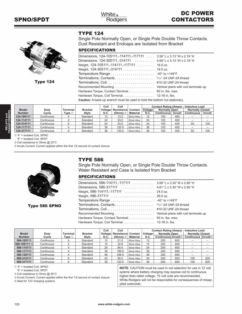
TYPE 124Single Pole Normally Open, or Single Pole Double Throw Contacts. Dust Resistant and Endcaps are Isolated from BracketSPECIFICATIONSDimensions, 24-05,-4,-7 . . . . 3.56”L x 3.3”W x 2.9”HDimensions, 24-305,-34 . . . . . . . . . . 4.69”L x 3.3”W x 2.9”HWeight, 24-05,-4,-7 . . . . . . . . . . 6.0 oz.Weight, 24-305,-34 . . . . . . . . . . . . . . . . . 9.0 oz.Temperature Range . . . . . . . . . . . . . . . . . . . . . . -40° to +49°FTerminations, Contacts . . . . . . . . . . . . . . . . . . . . 5/6”-24 UNF-2A threadTerminations, Coil . . . . . . . . . . . . . . . . . . . . . . . . #0-32 UNF-2A threadRecommended Mounting . . . . . . . . . . . . . . . . . . . . . . . Vertical plane with coil terminals upHardware Torque, Contact Terminal . . . . . . . . . . . . . . . 60 in. lbs. max.Hardware Torque, Coil Terminal . . . . . . . . . . . . . . . . . . 2-8 in. lbs.Caution: A back-up wrench must be used to hold the bottom nut stationary.
Type 124
Coil Coil Contact Rating (Amps) – Inductive Load Model Duty Terminal Bracket Voltage Resistance Contact Voltage Normally Open Normally Closed Number Cycle Type ➀ Style D.C. (Ohms) ➁ Material D.C. Continuous Inrush Continuous Inrush 124-105111 Continuous 4 Standard 2 3.2 Silver Alloy 2 00 400 – – 124-114111 Continuous 4 Standard 24 53.0 Silver Alloy 24 00 400 – – 124-314111 Continuous 6 Standard 24 53.0 Silver Alloy 24 00 400 50 00 124-117111 Continuous 4 Standard 36 20.0 Silver Alloy 36 00 400 – – 124-317111 Continuous 6 Standard 36 20.0 Silver Alloy 36 00 400 50 00➀ “4” = Isolated Coil, SPNO “6” = Isolated Coil, SPDT➁ Coil resistance in Ohms @ 25°C➂ Inrush Current: Current applied within the first 1/2 second of contact closure
TYPE 586Single Pole Normally Open, or Single Pole Double Throw Contacts. Water Resistant and Case is Isolated from BracketSPECIFICATIONSDimensions, 586-4,-7 . . . . . . . . . . . 3.69”L x 3.30”W x 2.90”HDimensions, 586-37 . . . . . . . . . . . . . . . . . 4.6”L x 3.30”W x 2.90”HWeight, 586-4,-7 . . . . . . . . . . . . . . . . . 24.0 oz.Weight, 586-37 . . . . . . . . . . . . . . . . . . . . . . . . . 26.0 oz.Temperature Range . . . . . . . . . . . . . . . . . . . . . . -40° to +49°FTerminations, Contacts . . . . . . . . . . . . . . . . . . . . 5/6”-24 UNF-2A threadTerminations, Coil . . . . . . . . . . . . . . . . . . . . . . . . #0-32 UNF-2A threadRecommended Mounting . . . . . . . . . . . . . . . . . . . . . . . Vertical plane with coil terminals upHardware Torque, Contact Terminal . . . . . . . . . . . . . . . 60 in. lbs. max.Hardware Torque, Coil Terminal . . . . . . . . . . . . . . . . . . 2-8 in. lbs.
Type 586 SPNO
Coil Coil Contact Rating (Amps) – Inductive Load Model Duty Terminal Bracket Voltage Resistance Contact Voltage Normally Open Normally Closed Number Cycle Type ➀ Style D.C. (Ohms) ➁ Material D.C. Continuous Inrush➂ Continuous Inrush➂
586-105111 Continuous 4 Standard 2 2.0 Silver Alloy 2 200 600 – – 586-108111➃ Continuous 4 Standard 5 32.8 Silver Alloy 5 200 600 – – 586-114111 Continuous 4 Standard 24 84.0 Silver Alloy 24 200 600 – – 586-117111 Continuous 4 Standard 36 89.0 Silver Alloy 36 200 600 – – 586-120111 Continuous 4 Standard 48 336.0 Silver Alloy 36 200 600 – – 586-314111 Continuous 6 Standard 24 84.0 Silver Alloy 24 200 600 00 200 586-317111 Continuous 6 Standard 36 20.0 Silver Alloy 36 200 600 00 200
➀ “4” = Isolated Coil, SPNO “6” = Isolated Coil, SPDT➁ Coil resistance in Ohms @ 25°C➂ Inrush Current: Current applied within the first 1/2 second of contact closure➃ Ideal for 2V charging systems
NOTE: CAUTION must be used in coil selection for use in 2 volt sytems where battery charging may expose coil to continuous, higher-than-rated voltage. 5 volt coils are recommended.White-Rodgers will not be responsible for consequences of misap-plied solenoids.
DC POWERCONTACTORSSPNO/SPDT