Embed Size (px)
Citation preview
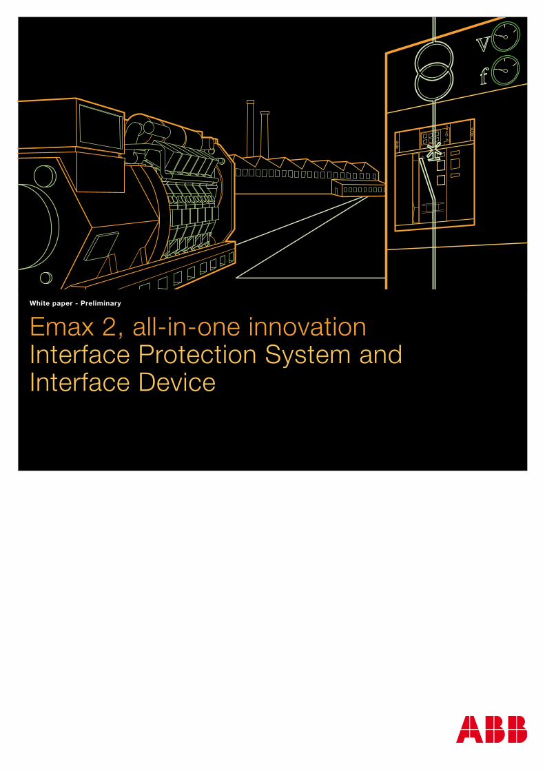
Emax 2, all-in-one innovationInterface Protection System and Interface Device
White paper - Preliminary

ABB | Interface Protection System and Interface Device 1
Index
General introduction ......................................................... 2
Emax 2 solution ................................................................ 2
Benefits ............................................................................ 2
General information on grid-connected operation............ 3
Technical rules for the connection of Active Users ............ 3
Prescribed Devices ......................................................... 4
Interface Device (ID) ....................................................... 4
Disconnection of the generating plant from the grid ......... 5
IPS and response to frequency changes .......................... 5
How it works ..................................................................... 6
Protection functions associated to the ID ......................... 6
Settings of the IPS ......................................................... 6
Local Command ............................................................. 8
Remote Disconnection.................................................... 8
Back-up in case of failure to open of the ID ..................... 8
Application scenarios ....................................................... 9
A-Emax 2 as Microgrid Main Circuit-Breaker ................... 9
B-Emax 2 as local generation Circuit-Breaker ............... 10
Programming on Ekip Connect ....................................... 11
Shopping list and wiring diagrams ................................. 18
Emax 2 with external voltage transformers .................... 18
Emax 2 with internal voltage outlets ............................. 20
Annex A - Definitions ...................................................... 22
Emax 2Interface Protection System and Interface Device
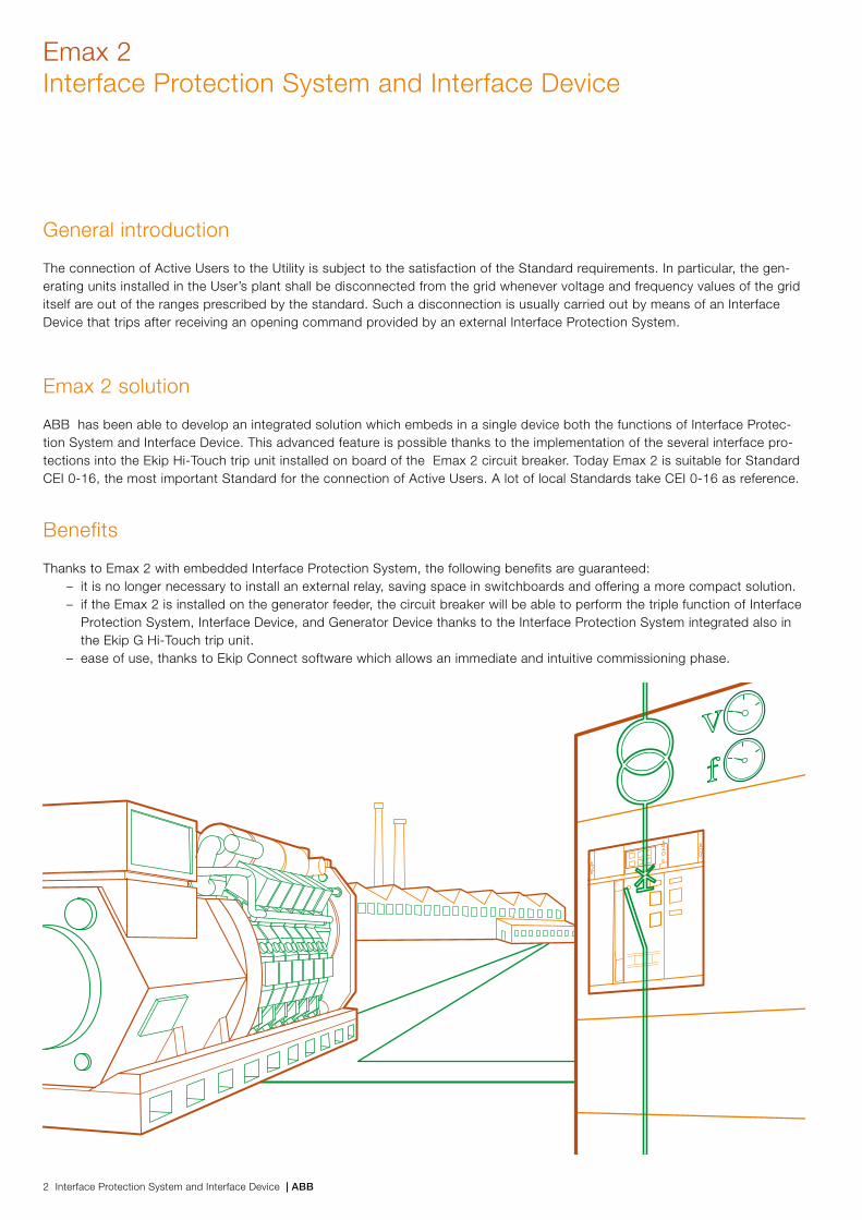
General introduction
The connection of Active Users to the Utility is subject to the satisfaction of the Standard requirements. In particular, the gen-erating units installed in the User’s plant shall be disconnected from the grid whenever voltage and frequency values of the grid itself are out of the ranges prescribed by the standard. Such a disconnection is usually carried out by means of an Interface Device that trips after receiving an opening command provided by an external Interface Protection System.
Emax 2 solution
ABB has been able to develop an integrated solution which embeds in a single device both the functions of Interface Protec-tion System and Interface Device. This advanced feature is possible thanks to the implementation of the several interface pro-tections into the Ekip Hi-Touch trip unit installed on board of the Emax 2 circuit breaker. Today Emax 2 is suitable for Standard CEI 0-16, the most important Standard for the connection of Active Users. A lot of local Standards take CEI 0-16 as reference.
Benefits
Thanks to Emax 2 with embedded Interface Protection System, the following benefits are guaranteed:– it is no longer necessary to install an external relay, saving space in switchboards and offering a more compact solution. – if the Emax 2 is installed on the generator feeder, the circuit breaker will be able to perform the triple function of Interface
Protection System, Interface Device, and Generator Device thanks to the Interface Protection System integrated also in the Ekip G Hi-Touch trip unit.
– ease of use, thanks to Ekip Connect software which allows an immediate and intuitive commissioning phase.
2 Interface Protection System and Interface Device | ABB
Emax 2Interface Protection System and Interface Device

General information on grid-connected operation
Technical rules for the connection of Active UsersIn case of Active Users connected to the MV distribution grid, the rules given in the Standard shall be complied with. In particu-lar, such rules apply to the Users’ generating plants with total power above 30 kW, or Users’ generating units with total genera-tion power exceeding 30% of the connection available power. Figure 1 shows the typical general scheme of connection for an Active User. In addition to the three prescribed devices, Figure 1 shows also the User’s generating units (priority loads) enabled or not to islanding operation in case of disconnection from the main grid.
Figure 1 - Typical connection diagram of an Active User
ACTIVE USER'S PLANT
PART OF MICROGRID NOT ENABLED TO ISLANDING OPERATION
GENERAL DEVICE (GD)
INTERFACE DEVICE (ID)
GENERATOR DEVICE (GenD)
GENERATOR
PART OF MICROGRID ENABLED TO ISLANDING OPERATION(PRIORITY LOADS)
POINT OF CONNECTION
MV DISTRIBUTION GRID
ABB | Interface Protection System and Interface Device 3
Prescribed Devices The devices to be provided when the User has grid-connected generating plants are:
– General Device (GD), placed immediately downstream of the point of connection and capable of disconnecting the whole User’s plant from the distribution grid. The GD can be realized by using either a MV three-pole circuit-breaker, withdraw-able version, equipped with shunt opening release or a MV three-pole circuit-breaker, equipped with shunt opening release and MV three-pole switch-disconnector installed on the supply side of the circuit-breaker itself;
– Interface Device (ID), able to ensure both the disconnection of part of the User’s plant (generators and possibly priority loads), thus allowing the loads to work in island-mode, as well as grid-connected operation;
– Generator Device (GenD), capable of excluding from the network the generating units only, separately. In case of LV gen-erating units, the GenD can consist of an automatic circuit-breaker.
The Standard CEI-016 and derived Standards allow one single device to perform more functions, based on the characteristics of the User’s plant, provided that, between the generating plant and the distribution grid, there are at least two circuit-breakers connected in series, or, as an alternative, one circuit-breaker and one contactor. In particular, the GenD can perform also the functions of the ID when having the necessary features.
Interface Device (ID)If the ID is installed on the LV side, it must consist of either an automatic circuit-breaker equipped with undervoltage release and controlled by the operator, or by a contactor coordinated with short-circuit protection devices suitable for disconnection. In case of plants with more generators, the interface device must be unique and such as to exclude all generators simulta-neously.
If required by the system, the use of multiple interface protections is admitted; but, in order not to affect and degrade the reliability of the system, the trip command of each protection must act on all the IDs present in the plant (the use of more IDs controlled by a single ISP is allowed). Thus, an abnormal condition detected even by a single ISP disconnects all the generators in the grid (“OR” logic function).
In case of installation of generators in already existing systems (grid-connected since at least one year), if the total power of the generators does not exceed 1000 kW, it is possible to install no more than three IDs, operating even without the “OR” logic function.
4 Interface Protection System and Interface Device | ABB
Emax 2Interface Protection System and Interface Device
Disconnection of the generating plant from the gridFunctioning of a generating plant working in parallel with the distribution grid is subject to definite conditions. In particular:
– grid-connected operation shall not cause service disruption on the distribution grid, so that high quality level of service is ensured for the other Users connected
– grid-connected operation shall be immediately and automatically interrupted in case of outage of the distribution grid or when the voltage and frequency values of the grid itself are out of the range of values defined by the Distribution System Operator (DSO);
– in case of voltage lack or voltage and frequency values on the distribution grid out of the range of values defined by the DSO, the parallel device of the generating plant shall not permit parallel-connection with the grid itself.
The ID guarantees disconnection of the generating plant from the grid in case of loss of mains.
In particular, the IPS, by acting on the ID, disconnects the generating plant from the distribution grid, thus preventing:– the User from supplying the distribution grid and leading to unintentional islanding conditions, in case of lack of voltage
on the grid itself;– the User from feeding the fault, in case of fault on the MV feeder line to which it is connected;– the conventional generator from being under such conditions to cause damages to the generator shaft itself in case of
automatic or manual reclosures of the circuit-breakers on the distribution grid.
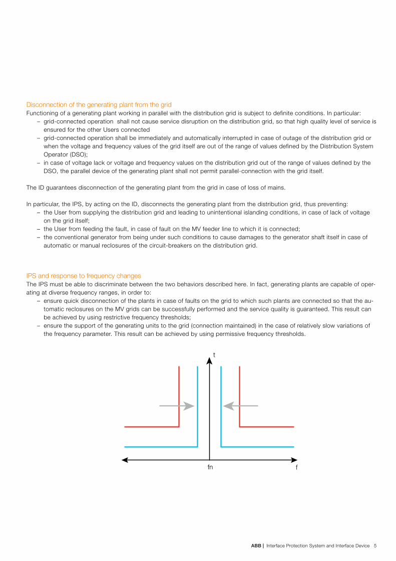
IPS and response to frequency changesThe IPS must be able to discriminate between the two behaviors described here. In fact, generating plants are capable of oper-ating at diverse frequency ranges, in order to:
– ensure quick disconnection of the plants in case of faults on the grid to which such plants are connected so that the au-tomatic reclosures on the MV grids can be successfully performed and the service quality is guaranteed. This result can be achieved by using restrictive frequency thresholds;
– ensure the support of the generating units to the grid (connection maintained) in the case of relatively slow variations of the frequency parameter. This result can be achieved by using permissive frequency thresholds.
fn
t
f
ABB | Interface Protection System and Interface Device 5

Settings of the IPSTable 1 shows the default settings of the IPS. If the DSO requires different values, they shall be specified when connecting the user’s plant to the grid.
Protection Tripping threshold Tripping time (1) ID Breaking time (2)
Overvoltage (ANSI 59, S1), based on the
calculation of the r.m.s. value
1.10 Un Variable as a function of the initial
and final voltage value
maximum value 603 s
The total breaking time of the ID
is obtained from the column on
the left by adding a maximum of
70 ms for MV and 100 ms for LV
equipment
Overvoltage (ANSI 59, S2) 1.20 Un 0.60 sUndervoltage (ANSI 27, S1) 3 0.85 Un 1.5 sUndervoltage (ANSI 27, S2) 4 0.3 Un 0.20 sVoltage-restrained overfrequency (ANSI
81>S1 restricted threshold) 5
50.2 Hz 0.15 s
Voltage-restrained underfrequency (ANSI
81<S1 restricted threshold) 5
49.8 Hz 0.15 s
Overfrequency (ANSI 81>S2 unrestricted
threshold) 5
51.5 Hz 1.0 s
Underfrequency (ANSI 81<S2 unrestricted
threshold) 5
47.5 Hz 4.0 s
Residual overvoltage (ANSI 59V0) 5% Um 6 25 sNegative sequence overvoltage (ANSI 59 Vi) 15% Un/En 7
Positive sequence undervoltage (ANSI 27 Vd) 70% Un/En 7
12345
6
7
A tolerance of ± 3% is allowedA tolerance of + 3% on the total is allowedMandatory threshold for static generators only.In case of conventional rotating generators, the value can be increased to 0.7 Un and t=0.150 s.For voltage values below 0.2 Un, the overfrequency and underfrequency protections shall be inhibited(disabled to give any command).Setting expressed as a percentage of the rated residual voltage Um measured at the ends of the open-delta configuration, or calculated inside the release (Um=3En=√3Un).Setting expressed as a percentage of the line-to-line voltage Un or as a percentage of the rated phase voltage En
Tab.1 – IPS settings
Emax 2Interface Protection System and Interface Device
How it works
Protection functions associated to the IDThe IPS associated with the ID requires a trip unit performing frequency, voltage and residual voltage protections. In addition, the IPS shall have a suitable voltage-restrained function for the detection of any fault condition on the MV grid.
Therefore, the following protections must be provided: 1. overvoltage (ANSI 59, with two thresholds);2. undervoltage (ANSI 27, with two thresholds);3. residual overvoltage on MV side (ANSI 59V0, delayed);4. voltage-restrained overfrequency (ANSI 81>threshold S1)5. voltage-restrained underfrequency (ANSI 81< threshold S1);6. overfrequency (ANSI 81>threshold S2, delayed);7. underfrequency (ANSI 81<threshold S2, delayed);
In particular, the voltage-restrained function is based on the following:– residual overvoltage protection (59V0, voltage-restrained for the activation of the restricted frequency thresholds);– negative sequence overvoltage protection (59Vi, voltage-restrained for the activation of the restricted frequency thresholds);– positive sequence undervoltage protection (27Vd, voltage-restrained for the activation of the restricted frequency thresholds).
6 Interface Protection System and Interface Device | ABB

Figure 2 shows the logic-operating diagram of the IPS.
Voltage measures
Residual overvoltage 59 V00.05÷0.50 Um
27.S20.05 Un ÷ 1 Un
27.S10.20 Un ÷ 1 Un
59.S11 Un ÷ 1.3 Un
59.S21 Un ÷ 1.3 Un
81<.S247 ÷ 50 Hz
81<.S147 ÷ 50 Hz
81>.S250 ÷ 52 Hz
81>.S150 ÷ 52 Hz
ID's undervoltage
releaseIPS trip
Negative sequence overvoltage 59 Vi0.40÷0.50 Un/En
Positive sequence undervoltage 27 Vd0.10÷0.90 Un/En
Local Command
Remote Disconnection
AND
OR
OROR
Voltage-restrained 81 V
T=0.1÷30s
T=3s
T=0.05÷5s
T=0÷0.2s
T=0.06÷5s
T=0.05÷1s
T=0.05÷5s
T=0.06÷5s
T=0.06÷5s
T=1÷240s
Fig.2
ABB | Interface Protection System and Interface Device 7
Local CommandIn the transient mode (stand-alone operation, no signals/commands by the DSO on the communication network), enabled by setting the “Local Command” associated to the “OR” gate of the voltage-restrained function, either low or high logic status is possible:
– if the “Local Command” is in low status (value “0”), it results into permanent operation with unrestricted thresholds, ex-cept when the voltage-restrained function 81V intervenes
– if the “Local Command” is in high status (value “1”), it results into permanent operation with restricted thresholds (due to any possible requirement of the DSO), regardless of the intervention of the voltage-restrained function 81V.
Remote DisconnectionWhen a fault occurs, the IPS is commanded to trip: in case of the communication network active, by the Remote Control, or in case of the communication network temporary inactive, by the voltage-restrained function 81 V.
The input status of the “Local Command” shall be low (default setting): as a consequence, the IPS works permanently with unrestricted thresholds. Only in case of DSO temporary requirements of increasing the IPS sensitivity, the “Local Command” status can be high (temporary authorization by the Transmission System Operator).
Back-up in case of failure to open of the IDFor the safe operation of the grid, for active plants with power ratings above 400 kW, it is necessary to provide a back-up in case of failure to open of the interface device. The back-up consisting in transferring the trigger command (issued by the IPS) to another tripping device, is constituted by a circuit (conditioned by the closed position of the interface device), which acts on the GD or on the GenD(s), with a delay not exceeding 1 s. Restoring of the back-up device must be performed only manually.
Emax 2Interface Protection System and Interface Device
8 Interface Protection System and Interface Device | ABB

ABB has been able to integrate in a single device the following functions to be used in the scenarios described below. Thanks to these embedded functions, the number of devices to be installed is reduced, with consequent space saving inside the switchboard.
To open the ID in case of an event shown in the logic scheme of Figure 2, the following digital inputs/outputs shall be used by means of Ekip Signalling 2K or 4K or 10K module:
– 1 input to receive the Local Command signal– 1 input to receive the Remote Disconnection signal– 1 output to command the undervoltage release YU – 1 output to fulfil the back-up function in case the circuit-breaker has not tripped after 1s from the command to the YU
(during the operation).– 1 output to verify the voltage restrained signal (only during the on-site tests).
Emax 2 with embedded Interface Protection System have been tested and certified in compliance with the Standard CEI 0-16 and are suitable for the following scenarios.
A - Emax 2 as Microgrid Main Circuit-BreakerIn such scenario (Figure 3), Emax 2 with embedded Interface Protection System can fulfill the double function of Interface Device and Interface Protection System. In case of IPS tripping, the LV microgrid downstream of the main circuit-breaker Emax 2 remains active thanks to both the local generation and the load shedding feature also embedded in the main circuit-breaker Emax 2.
Application scenarios
Fig. 3 – Emax 2 as Microgrid Main Circuit-Breaker
Utility
IPS+ID
GD
MV/LV Transformer
Loads
EnergyStorageSystem
PVPlant
Wind Plant Gen Set
G
ABB | Interface Protection System and Interface Device 9
To be used in this scenario, the main circuit-breaker Emax 2 (E1.2..E6.2, fixed or withdrawable) has to be equipped with:– Trip unit Ekip Hi-Touch– Interface Protection System function– Ekip Supply module 24/48Vdc and a switch mode power supply (Input 100-240Vac, Output 24Vdc)1
– Ekip 2K or 4K or 10K Signalling module to send/receive I/O signals– Undervoltage release YU– Set of three voltage transformers TJC (recommended) connected in open-delta configuration for MV zero-sequence de-
tection2
– Ekip Sinchrocheck3 module to receive the signal from the three previous VTs in open-delta configuration– Ekip Test & Programming Unit to connect the trip unit to a PC where the Ekip Connect software has to be installed.
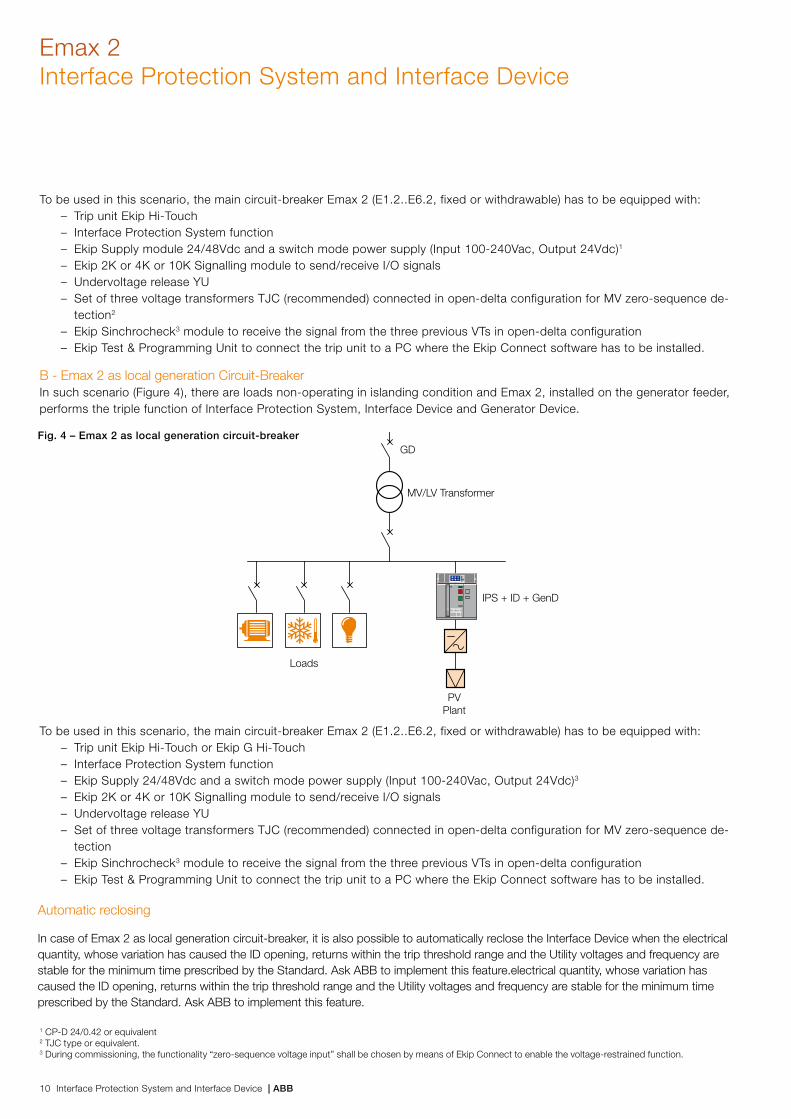
B - Emax 2 as local generation Circuit-BreakerIn such scenario (Figure 4), there are loads non-operating in islanding condition and Emax 2, installed on the generator feeder, performs the triple function of Interface Protection System, Interface Device and Generator Device.
1 CP-D 24/0.42 or equivalent2 TJC type or equivalent.3 During commissioning, the functionality “zero-sequence voltage input” shall be chosen by means of Ekip Connect to enable the voltage-restrained function.
To be used in this scenario, the main circuit-breaker Emax 2 (E1.2..E6.2, fixed or withdrawable) has to be equipped with:– Trip unit Ekip Hi-Touch or Ekip G Hi-Touch– Interface Protection System function– Ekip Supply 24/48Vdc and a switch mode power supply (Input 100-240Vac, Output 24Vdc)3
– Ekip 2K or 4K or 10K Signalling module to send/receive I/O signals– Undervoltage release YU– Set of three voltage transformers TJC (recommended) connected in open-delta configuration for MV zero-sequence de-
tection– Ekip Sinchrocheck3 module to receive the signal from the three previous VTs in open-delta configuration– Ekip Test & Programming Unit to connect the trip unit to a PC where the Ekip Connect software has to be installed.
Fig. 4 – Emax 2 as local generation circuit-breaker
Emax 2Interface Protection System and Interface Device
Utility
IPS + ID + GenD
GD
MV/LV Transformer
Loads
PVPlant
Automatic reclosing
In case of Emax 2 as local generation circuit-breaker, it is also possible to automatically reclose the Interface Device when the electrical quantity, whose variation has caused the ID opening, returns within the trip threshold range and the Utility voltages and frequency are stable for the minimum time prescribed by the Standard. Ask ABB to implement this feature.electrical quantity, whose variation has caused the ID opening, returns within the trip threshold range and the Utility voltages and frequency are stable for the minimum time prescribed by the Standard. Ask ABB to implement this feature.
10 Interface Protection System and Interface Device | ABB
Programming on Ekip ConnectABB Emax 2 Ekip Hi-Touch trip unit is very sophisticated and offers many advanced features. In order to function properly, it has to be programmed in a specific way to enable the desired functions. In this section, we will outline the steps to complete the programming of the IPS feature.
1. Launch the free Ekip Connect software on the customer laptop.
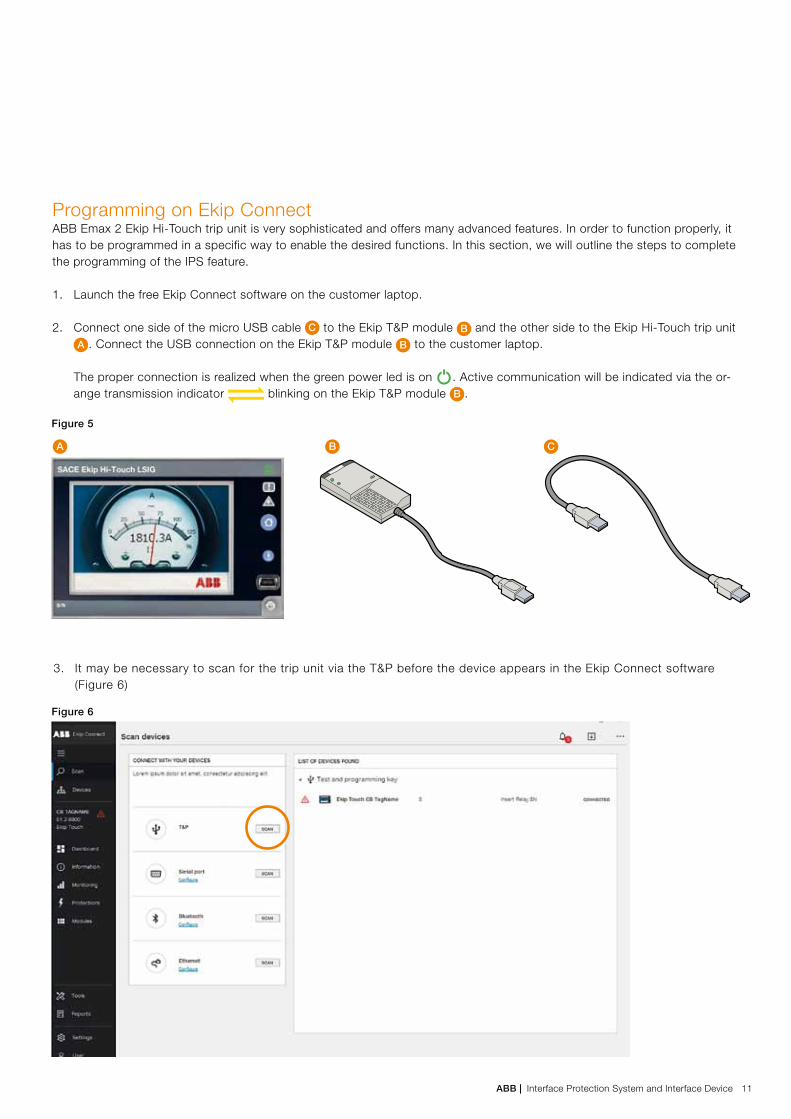
2. Connect one side of the micro USB cable C to the Ekip T&P module B and the other side to the Ekip Hi-Touch trip unit A . Connect the USB connection on the Ekip T&P module B to the customer laptop.
The proper connection is realized when the green power led is on . Active communication will be indicated via the or-ange transmission indicator blinking on the Ekip T&P module B .
B CA
Figure 6
Figure 5
3. It may be necessary to scan for the trip unit via the T&P before the device appears in the Ekip Connect software (Figure 6)
ABB | Interface Protection System and Interface Device 11

Emax 2Interface Protection System and Interface Device
4. Choose the “Interface Protection System” feature from the Menu “Tools” on the left side. Then, select the configuration that suits the plant settings (Fig. 7)
Figure 7
12 Interface Protection System and Interface Device | ABB
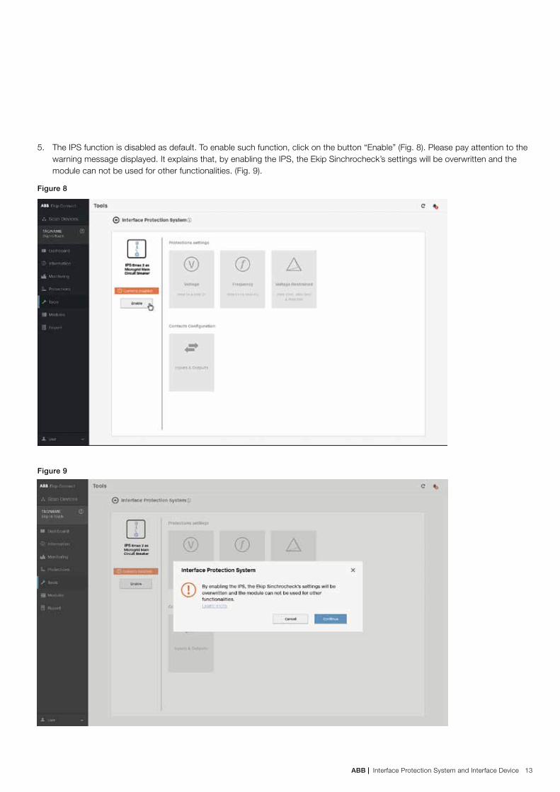
5. The IPS function is disabled as default. To enable such function, click on the button “Enable” (Fig. 8). Please pay attention to the warning message displayed. It explains that, by enabling the IPS, the Ekip Sinchrocheck’s settings will be overwritten and the module can not be used for other functionalities. (Fig. 9).
Figure 8
Figure 9
ABB | Interface Protection System and Interface Device 13

Emax 2Interface Protection System and Interface Device
Figure 11
6. By pressing the relevant push button (Fig. 10) for protections and contacts, it is possible to set thresholds and timing of each protection (Fig. 11) and to choose the several inputs/outputs to perform the functions indicated (Fig.12).
To save each setting, click on the “Save” button. To transfer all the protection settings and the contact configurations to the Trip Unit, click on the “Transfer” button. NOTE: It is possible to return to the page with the two-plant configuration by clicking on “change” under the IPS symbol.
Figure 10
14 Interface Protection System and Interface Device | ABB

Figure 12
7. By clicking on the “Test” button, under the “Operating Condition” (Fig.12), it is possible to set the output for the Voltage Re-strained Signal verification during the on-site tests.
ABB | Interface Protection System and Interface Device 15
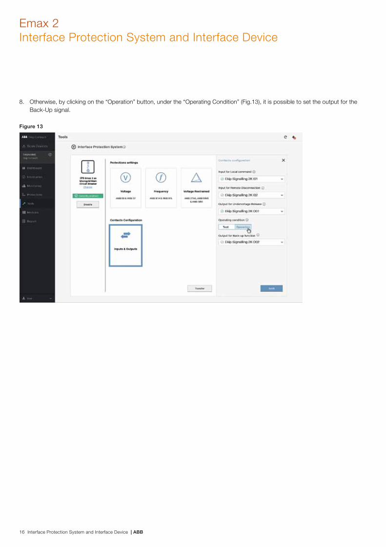
Figure 13
8. Otherwise, by clicking on the “Operation” button, under the “Operating Condition” (Fig.13), it is possible to set the output for the Back-Up signal.
Emax 2Interface Protection System and Interface Device
16 Interface Protection System and Interface Device | ABB

Figure 15
Figure 14
9. If the second configuration is chosen (Fig. 14), there will be additional outputs which will be to be set (Fig. 15) to make it possible to perform the automatic reclosing.
ABB | Interface Protection System and Interface Device 17

Shopping list and wiring diagrams
Two configurations can be used with the IPS embedded in the circuit-breaker.
Emax 2 with external voltage transformersThe configuration with the external VTs has to be used both in the withdrawable version of Emax 2, and – in existing plants only - in the fixed version.
Example of shopping list and relevant ordering codes:
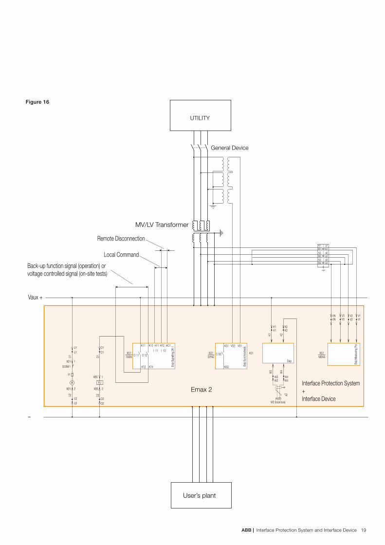
Figure 16 shows the wiring diagram with the wiring to be carried out at the relevant terminals of Emax 2 in the scenario with external voltage transformers.
E2.2N 2500 Ekip Hi-Touch LSIG 4p WMP 1SDA073049R1
E2.2 W FP Iu=2500 4p HR HR 1SDA073912R1
Interface Protection System feature 1SDA082919R1
Ekip Supply 24-48Vdc 1SDA074173R1
Ekip Signalling 2K-1 1SDA074167R1
YU E1.2..E6.2 220-240 Vac/dc 1SDA073700R1
External installed voltage outlets 1SDA074217R1
Ekip Synchrocheck E1.2..E6.2 1SDA074183R1
Ekip T&P – Programming and Test Unit 1SDA066989R1
3 x Voltage transformers TJC E43925370 (or equivalent)
3 x Voltage transformers Customer's choice with accuracy 0.2
Switch mode power supply 1SVR427041R0000 (or equivalent)
Emax 2Interface Protection System and Interface Device
18 Interface Protection System and Interface Device | ABB
UTILITY
General Device
MV/LV Transformer
Emax 2
User’s plant
Ekip
Sync
hroc
heck
Ekip
Mea
surin
g Pr
o
Ekip
W4W4
(A) (B)
W3W3
W2 (local bus)
*Q)
K51
K1K1
K2K2
Ekip
Sign
alling
2K-
1 VS1VS2KS1K11 K13
K12 K14
H11 H12 HC1
KS2
OOI
11 O
D1D1
D1
D2D2
D2
U1U1
XB1
S33M/1
F1
1
XB1
XB5 1
2 XB5 2
U1
U2U2
U2
1211 I 12
SCK51SYNC
K51MEAS
Interface Protection System + Interface Device
Vaux +
Back-up function signal (operation) orvoltage controlled signal (on-site tests)
Local Command
Remote Disconnection
–
K51SIGN
YUM
K1 K2W
4
W3
VNVN
V3V3
b3
b2
b1
B3
B2
B1
a3
a2
a1
A3
A2
A1
V2V2
V1V1
Figure 16
ABB | Interface Protection System and Interface Device 19

Emax 2 with internal voltage outletsThe configuration with the internal voltage outlets can be used on the fixed version of Emax 2 in new plants5. In such case, the internal voltage outlets can be placed either on the Utility side of the circuit-breaker or on the User’s plant side6. In the latter case, the IPS is temporarily deactivated in case of ID opened with positive security circuit (in accordance with the Standard).
Example of shopping list for the upper internal voltage outlet configuration and relevant ordering codes:
E1.2N 1600 Ekip Hi-Touch LSIG 4p F 1SDA071519R1
Interface Protection System feature 1SDA082919R1
Ekip Supply 24-48Vdc 1SDA074173R1
Ekip Signalling 2K-1 1SDA074167R1
YU E1.2..E6.2 220-240 Vac/dc 1SDA073700R1
Upper internal installed voltage outlets 1SDA074216R1
Ekip Synchrocheck E1.2..E6.2 1SDA074183R1
Ekip T&P – Programming and Test Unit 1SDA066989R1
3 x Voltage transformers TJC E43925370 (or equivalent)
Switch mode power supply 1SVR427041R0000 (or equivalent)
5 Plants not yet connected to the Utility.6 In order to repeat periodically the on-site tests (as prescribed by the Standard) by injecting the test signals directly on the circuit-breaker terminals/busbars connected, it is
recommended to disconnect the side on which the internal voltage sockets are installed.
Emax 2Interface Protection System and Interface Device
The Interface Protection System feature can be also purchased as loose accessory with the same code 1SDA082919R1. In such case, the previous accessory lists remain valid. A USB key will be delivered with the SW license linked to the circuit breaker Serial Number.
20 Interface Protection System and Interface Device | ABB

UTILITY
General Device
MV/LV Transformer
Emax 2
User’s plant
Ekip
Sync
hroc
heck
Ekip
Mea
surin
g Pr
o
Ekip
W4W4
(A) (B)
W3W3
W2 (local bus)
*Q)
K51
K1K1
K2K2
Ekip
Sign
alling
2K-
1 VS1VS2KS1K11 K13
K12 K14
H11 H12 HC1
KS2
OOI
11 O
D1D1
D1
D2D2
D2
U1U1
XB1
S33M/1
F1
1
XB1
XB5 1
2 XB5 2
U1
U2U2
U2
1211 I 12
SCK51SYNC
K51MEAS
Interface Protection System + Interface Device
Vaux +
Back-up function signal (operation) orvoltage controlled signal (on-site tests)
Local Dommand
Remote Disconnection
–
L1 L2 L3 N
K51SIGN
YUM
K1 K2W
4
W3
Figure 17
ABB | Interface Protection System and Interface Device 21

Emax 2Interface Protection System and Interface Device
22 Interface Protection System and Interface Device | ABB
Annex A - Definitions
Priority loads in a plantThe electrical loads to which the User wants to ensure particular service continuity. In case of islanded operation (disconnected from the distribution grid), priority loads are typically supplied by the generating plant after tripping of the Interface Device (ID). Priority loads include essential loads.
General Device (GD)Protection, switching and disconnection device whose tripping (commanded by the General Protection System) ensures the disconnection of the whole User’s plant from the DSO grid. In case of a plant having a single feeder (immediately downstream of the connecting cable) the GD is unique. In case of more feeders (immediately downstream of the connecting cable), the GD can be constituted by two Line General Devices.
Interface Device (ID)One (or more) switching device whose tripping (commanded by a dedicated protection system) ensures the disconnection of the generating plant from the Utility, thus allowing the generating plant to supply priority loads while operating in islanded mode.
Back-up device Device with suitable switching, tripping and disconnection characteristics. Its tripping disconnects the DSO grid from the gen-erating units of the User in case of tripping of the Interface Protections and failure to open by the ID. The back-up device may coincide with the General Device, with the Generator Device or with any other device interposed between the two of them. It shall never be the same as the ID.
Generator Device (GenD)Switching and protection device whose tripping (commanded by a dedicated protection system) causes the disconnection of the generating units.
Power available for absorptionThe maximum power that can be absorbed from a connection point.
Power available for injectionThe maximum power that can be fed into a point of connection without causing the User’s disconnection.
Connection available powerMaximum value between the power available for absorption and the power available for injection.
Interface Protection (IP)Set of protections used to monitor the frequency and voltage parameters of the DSO grid. The IP is required in case of gen-erating plants parallel-connected with the DSO grid. It acts on the ID through positive logic relays (i.e. excited in case of grid parameters within the set limits in the presence of auxiliary voltage).
Connection PointsPhysical boundary between two grids - under the ownership and/or management of two different entities - through which the physical exchange of energy takes place.
Interface Protection System (IPS)Protection system associated to the Interface Device, consisting of:
– voltage transformers/transducers, with the relevant connections to the protection trip unit; – interface protection (IP) with relevant supply;– tripping circuits of the circuit-breaker (ID).
Active UsersUsers that utilize any machine (rotary or static) that converts all forms of useful power into alternating current energy and can operate in parallel (even transient) with the grid. This category include also all users installing storage systems other than UPS.

Contact us
The data and illustrations are not binding. We reserve the right to modify the contents of this document on the basis of technical development of the products, without prior notice.
Copyright 2016 ABB. All rights reserved.
1SD
C00
7117
G02
02 -
05/
2017For more information please contact:
ABB SACEA division of ABB S.p.A.L.V. BreakersVia Pescaria, 524123 Bergamo - Italy Tel.: +39 035 395 111 Fax: +39 035 395306-433 www.abb.com