Embed Size (px)
Citation preview

120-90-321-002-EH-1112.pdf
WHITE PAPER
Measurements with the KMA36 (optional: Demo board G-MRMO-024)
120-90-321-002-EH-1112
120-90-321-002-EH-1112.pdf
2 of 13
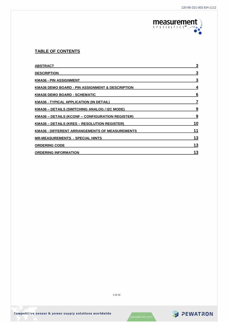
TABLE OF CONTENTS
ABSTRACT 3
DESCRIPTION 3
KMA36 - PIN ASSIGNMENT 3
KMA36 DEMO BOARD - PIN ASSIGNMENT & DESCRIPTION 4
KMA36 DEMO BOARD - SCHEMATIC 6
KMA36 - TYPICAL APPLICATION (IN DETAIL) 7
KMA36 – DETAILS (SWITCHING ANALOG / I2C MODE) 9
KMA36 – DETAILS (KCONF – CONFIGURATION REGISTER) 9
KMA36 – DETAILS (KRES – RESOLUTION REGISTER) 10
KMA36 - DIFFERENT ARRANGEMENTS OF MEASUREMENTS 11
MR-MEASUREMENTS - SPECIAL HINTS 13
ORDERING CODE 13
ORDERING INFORMATION 13
120-90-321-002-EH-1112

120-90-321-002-EH-1112.pdf
White Paper
Measurements with the KMA36 (optional: Demo board G-MRMO-024)
3 of 13
ABSTRACT
Angle positioning as well as linear displacement measurements are widely used in many industrial domains such as automation or robotic. Often these applications require good accuracy, very good repeatability and a fast response time. Magneto-resistive sensors are very well suited for measuring angles, rotations and positions contactless very precisely. The main drawback of many sensors is the need of sensitive measuring circuits to convert the sensor signals into useful data. This application note focuses on the versatile applicable KMA36 which is an easy-to-use solution with a built-in MR sensor expanded by an ASIC making data available either as an individually customized analog signal or as digital data.
DESCRIPTION
The KMA36 is magnetic universal encoder for precise rotational or linear measurements. This system-on-chip combines a magneto resistive element along with analog to digital converter and signal processing in a standard small SOIC package. By using the well established Anisotropic Magneto Resistive technology, the KMA36 is able to determine contactless the magnetic angle of an external magnet over 360°, as well as the incremental position on a magnetic pole strip with 5 mm pole length. Mounted on the KMA36 Demo board G-MRMO-024 the configuration and data communication (I2C) as well as the analog signal output are easily accessible via pinheads. Some rarely changed configurations (like I2C address) are set by solder-jumper on the backside of the board.
KMA36 - PIN ASSIGNMENT
Pin No.
KMA36 TSSOPSymbol Type Description
1 A1 NC Not connected
2 A0 I Slave adress configuration pin
3 DVCC_SE O Drive pin to power sensor
4 SDA I/O Two-wire interface data pin
5 PWM O PWM output
6 SCL I Two-wire interface clock pin
7 GND_SE S Sensor supply ground pin
8 VCC_SE S Sensor power supply pin
9 NC NC Not connected
10 NC NC Not connected
11 NC NC Not connected
12 COILP I Coil power supply pin
13 COILN I Coil power supply pin
14 AREF I Asic analog reference
15 NC NC Not connected
16 GND_AS S Asic supply ground
17 NC NC Not connected
18 VCC_AS S Asic power supply
19 DCOILN O Drive pin to coil power supply
20 DCOILP O Drive pin to coil power supply
Figure 1: Pin assignment of KMA36 (for further details please refer the KMA36 datasheet)
120-90-321-002-EH-1112

120-90-321-002-EH-1112.pdf
White Paper
Measurements with the KMA36 (optional: Demo board G-MRMO-024)
4 of 13
KMA36 DEMO BOARD- PIN ASSIGNMENT & DESCRIPTION
Top View
Pin Function Description
J9.1 SCL I2C serial clock
J9.2 Gnd Power ground
J9.3 SDA I2C serial data
J9.4 5V DC Power +5V DC
J9.5 Gnd Power ground
J9.6 5V DC Power +5V DC
J9.7 PWM Analog mode - pwm output signal
J9.8 A1 Reserved – do not connect
J9.9 Aout Analog mode - analog output signal (0..5V DC)
J9.10 A0 Configuration pin (please refer the KMA36 datasheet)
J7.1 A0 Configuration pin (please refer the KMA36 datasheet)
J7.2 DcoilP Analog mode: Connect to J7.1 to set analog mode zero reference angle I2C mode: Connect to J7.1 to set I
2C slave address to 0x5A
J9 J7
1
1
120-90-321-002-EH-1112

120-90-321-002-EH-1112.pdf
White Paper
Measurements with the KMA36 (optional: Demo board G-MRMO-024)
5 of 13
Bottom View
Jumper Function /Name
Mode Description
J1 NC_DIR Analog Rotation direction configuration (connect for clockwise) (open by default)
J2 STD_NC Analog Set this jumper to permanently power the internal MR-sensor. (set by default)
J3 PWR_NC Analog Set this jumper to control the power of the internal MR-sensor by software (used by ‘low power mode’) (open by default)
J2 / J3 Do not set J2 and J3 at the same time
J5 OUT_10% Analog
Set this jumper to adjust an output voltage of 10% (0.5V DC) at the dedicated zero reference angle (0 degree) (set by default)
I2C Set this jumper to set I2C slave address to 0x5C
J6 OUT_25% Analog
Set this jumper to adjust an output voltage of 25% (1.25V DC) at the dedicated zero reference angle (0 degree) (open by default)
I2C Set this jumper to set I2C slave address to 0x5B
J8 OUT_50% Analog
Set this jumper to adjust an output voltage of 50% (2.5V DC) at the dedicated zero reference angle (0 degree) (open by default)
I2C Set this jumper to set I2C slave address to 0x59
J5 / J6 / J8
Do not set J5 and/or J6 and/or J8 at the same time
J5 J3
J1 J2
J8
J6
120-90-321-002-EH-1112

120-90-321-002-EH-1112.pdf
White Paper
Measurements with the KMA36 (optional: Demo board G-MRMO-024)
6 of 13
KMA36 DEMO BOARD - SCHEMATIC
120-90-321-002-EH-1112

120-90-321-002-EH-1112.pdf
White Paper
Measurements with the KMA36 (optional: Demo board G-MRMO-024)
7 of 13
KMA36 - TYPICAL APPLICATION (IN DETAIL)
Typical application using the analog mode
Part Function Comment
C1 Buffer to power supply gnd Optional but recommended
C2 Power supply stabilization Optional but recommended
C3 Power supply stabilization Optional but recommended
C4 Analog reference stabilization Optional but recommended
C5 Cap. of 1. order passive low pass Converting PWM to analog voltage
R2 Part of voltage divider to provide 2V to
AREF Please refer to the KMA36 datasheet for details
R3 Series resistor of coil Coil = 100R (typ), R2 = 150R, Rseries = 250R,
ICoil = 20mA (recommended)
R4 Res. of 1. order passive low pass Converting PWM to analog voltage
R5 Part of voltage divider to provide 2V to
AREF Please refer to the KMA36 datasheet for details
R6 Pull up resistor at A0 example, please refer datasheet for A0-options
SE1 KMA36 IC -
IC1 OPAmp, impedance converter for low-pass (example MCP6231) use rail-to-rail OPAmp
120-90-321-002-EH-1112

120-90-321-002-EH-1112.pdf
White Paper
Measurements with the KMA36 (optional: Demo board G-MRMO-024)
8 of 13
Typical application using the I2C mode
Part Function Comment
C2 Power supply stabilization Optional but recommended
C3 Power supply stabilization Optional but recommended
C4 Analog reference stabilization Optional but recommended
R2 Part of voltage divider to provide 2V to
AREF Please refer to the KMA36 datasheet for details
R3 Series resistor of coil Coil = 100R (typ), R2 = 150R, Rseries = 250R,
ICoil = 20mA (recommended)
R5 Part of voltage divider to provide 2V to
AREF Please refer to the KMA36 datasheet for details
SE1 KMA36 IC -
120-90-321-002-EH-1112

120-90-321-002-EH-1112.pdf
White Paper
Measurements with the KMA36 (optional: Demo board G-MRMO-024)
9 of 13
KMA36 – DETAILS (SWITCHING ANALOG / I2C MODE)
The KMA36 will always start in analog mode. To switch into I2C mode no special configuration is necessary. Calling the KMA36 via the two wire bus the first time will switch from analog-mode into digital mode. The analog output is disabled until the next power up to keep the performance high. (Calling means to start an I2C data transfer with the correct I2C address of the KMA36. This address is configured by hardware
1) – see above)
1)
On demo board G-MRMO-024: jumper J5..J8
KMA36 – DETAILS (KCONF – CONFIGURATION REGISTER)
SLP-Bit: If the sleep-mode bit is set to ‘1’ and the KCONF register is transmitted to the KMA36 the IC will fall immediately into sleep mode. While in sleep mode no measurements are done (no internal registers will be updated) and the analog output voltage will fall to zero volts. However, the KMA36 will listen to the I2C bus. If a message received which address fits, the KMA36 will wake up and restart working. For low-power applications with lower repetition rate a continuous ‘polling’ can be a solution to effectively decrease power consumption:
write KCONF (SLP=1) wait until measure is necessary read DATA write KCONF (SLP=1)
LIN-Bit: The LIN-Bit enables recalculation algorithms to adjust the sensor data to measurements
with a 5mm pole strip (please refer to the datasheet for more details of this strip) for linear measures. These algorithms will only work with the dedicated 5mm pole strip and designed to reduce harmonics which will overlay the linear position data.
CNT-Bit: Setting the CNT-Bit to ‘1’ enables the internal 4 Byte (31 Bit + sign) incremental counter.
This counter will be written in respect to the configured resolution. For example, if the resolution (KRES) is set to ‘3600’ (that means that a full rotation of a disc magnet is given in steps of 0.1°) a rotation of 3 full turns will saved as 3600 x 3 = 10800. (or -10800, dependent of the direction)
Using the maximum (recommended 1)
) resolution of 13bit (a full resolution is saved in 8192 steps = 0.04°) the counter register is large enough to save more than 260 thousands turns before a data overflow will corrupt the data.
Reset of the counter register: The register will be cleared every time data is received via the
I2C bus. Using the incremental counter will have a little influence to the cycle time (update rate).
Dependent on other configurations the cycle time may be reduced up to 3%. 1)
Please refer to the KREF section of this application note for details of the resolution.
PWR-Bit: Setting the PWR-Bit to ‘1’ enables the low-power-mode. In this mode the internal coil is not
used. Not in low-power-mode the coil is powered ~50% of the duty cycle. Using low-power-mode will reduce the power consumption by the value of the coil-power determined by the supply voltage and the external coil series resistor multiplied by 50%:
Example:
power supply 5VDC
series resistor 150R coil current = 20mA , x 50% duty cycle = 10mA coil power = 5V x 10mA = 50mW
SPD-Bit: Please refer the datasheet for details. ( update rate section)
120-90-321-002-EH-1112

120-90-321-002-EH-1112.pdf
White Paper
Measurements with the KMA36 (optional: Demo board G-MRMO-024)
10 of 13
KMA36 – DETAILS (KRES – RESOLUTION REGISTER)
Although the internal measure processes work with a resolution up to 15 bit (32768 steps) it is recommended to use a resolution of 13bit or less. Beyond this level the Linearity error will rise above the datasheet specification and ‘missing codes’ cannot be excluded. The value written in the resolution-register (default/initial: ‘32768’) must be between 1 and 32768. Any other value would lead to unexpected system behavior. The value stored in the register represents the equivalence to a full 360 degree rotation of the applied magnetic field. In other words:
resolution of ‘360’ produce values (Bytes MA0-MA1) where 1 digit represents 1° 1)
resolution of ‘3600’ produce values (Bytes MA0-MA1) where 1 digit represents 0.1° 1)
resolution of ‘8192’ produce values (Bytes MA0-MA1) where 1 digit represents 360°/8192 = 0.044° 2)
resolution of ‘1000’ produce values (Bytes MA0-MA1) where 1 digit represents 360°/1000 = 0.36° 3)
1)
This settings suits to angle measurements with desired results in degrees 2)
Recommended maximum resolution 3)
This settings suits to linear measurements with the 5mm pole strip: one pole-pair equals 10mm. A resolution set to ‘1000’ will produce values where 1 digit represents 10mm /1000 = 10µm
120-90-321-002-EH-1112

120-90-321-002-EH-1112.pdf
White Paper
Measurements with the KMA36 (optional: Demo board G-MRMO-024)
11 of 13
KMA36 - DIFFERENT ARRANGEMENTS OF MEASUREMENTS
The KMA36 is recommended for two measurement arrangements:
1) Rotational (angle) measurement with disc-magnet that is placed exactly over the magnetic center of the KMA36.
In this arrangement it does not matter if the disc is placed over the top of the KMA36 or under the PCB. However, placing the magnet on top allows a minimization of the distance (gap) between the magnet and the sensor. A gap as small as possible is necessary for accurate measurement and good results.
2) Linear measurement (measurement of linear movement) with a magnetic pole strip.
Due to complex physical interrelations for this kind of arrangement more parameters will have to be respected:
a) The pole length has to be 5mm (typical accuracy: +/- 40µm / m) b) The pole strip must be placed rectangular and as close as possible to the short side of
the KMA36 (please refer to the drawing)
120-90-321-002-EH-1112

120-90-321-002-EH-1112.pdf
White Paper
Measurements with the KMA36 (optional: Demo board G-MRMO-024)
12 of 13
These two modes of arrangement are recommended for best results. In addition the KMA36 is calibrated for this orientations and arrangements. Realizing arrangements as described above will produce high resolution linear correlations between angle/rotation and converted data (analog or digital) or linear position and converted data (analog or digital). Enabling the software configurable LIN-Bit the KMA36 will be set in an optimized mode of operation for linear measurement. We strongly recommend setting this bit when using a linear arrangement. In addition to these two arrangements there are many more possible designs combining a magnet (disc / scale / rod / ...) and the KMA36. Please refer to the KMA36 Application Notes to find examples of the different measurement arrangements. Deviation from the recommended arrangements does not necessarily leads to unusable designs. Placing the magnet to other positions and / or axis will result in non-linear data and a (possible) reduction of accuracy. Especially when using the I2C mode (which means that the received data will be post-processed by a microcontroller or PC) the master application will be able to use a correction calculation or just use a tailored LUT (look-up-table) to recover the linear correlation. We recommend test measures with a concrete design to get a better idea of the available data.
In the following we show a few examples of arrangements and the expected data
Description Arrangement Data
Rotational / angle
magnet disc placed over magnetic
sensor center
Linear position
(relative) with pole strip
120-90-321-002-EH-1112

120-90-321-002-EH-1112.pdf
White Paper
Measurements with the KMA36 (optional: Demo board G-MRMO-024)
13 of 13
MR-MEASUREMENTS - SPECIAL HINTS
To get best results with maximum repeatability take care of a few points regarding the arrangement:
Keep the gap as small as possible
Pay attention to mechanical tolerances and repeatability of the mechanical design
Keep in mind that the magnetic axis of the KMA36 is not the center of the IC
Please refer the following image to see the default magnetic reference angle configuration
ORDERING CODE
Product Description Article number
KMA36 KMA36 TSSOP20 G-MRMO-031
DemoBoard Demo board for KMA36 G-MRMO-024
Measurement Specialties reserves the right to change the specification without notice, in order to improve the design and performance of the product.
The information in this sheet has been carefully reviewed and is believed to be accurate; however, no responsibility is assumed for inaccuracies. Furthermore, this information does not convey to the purchaser of such devices any license under the patent rights to the manufacturer. Measurement Specialties, Inc. reserves the right to make changes without further notice to any product herein. Measurement Specialties, Inc. makes no warranty, representation or guarantee regarding the suitability of its product for any particular purpose, nor does Measurement Specialties, Inc. assume any liability arising out of the application or use of any product or circuit and specifically disclaims any and all liability, including without limitation consequential or incidental damages. Typical parameters can and do vary in different applications. All operating parameters must be validated for each customer application by customer’s technical experts. Measurement Specialties, Inc. does not convey any license under its patent rights nor the rights of others.
90°
0°
KMA36
N
N S
S
120-90-321-002-EH-1112

Competitive sensor & power supply solutions worldwide
Headquarter Switzerland:Pewatron AG Thurgauerstrasse 66CH-8052 Zurich Phone +41 44 877 35 [email protected]
Offi ce Germany:Pewatron AG Edisonstraße 16D-85716 UnterschleißheimPhone +49 89 260 38 [email protected]
Sales Austria
Kurt StritzelbergerPewatron AG Edisonstraße 16D-85716 Unterschleißheim
Phone + 49 89 260 52 80Mobile + 49 171 803 41 35
Sales Switzerland & Liechtenstein
Postcode 3000 – 9999
Basil FreiPewatron AGThurgauerstrasse 66CH-8052 Zurich
Phone + 41 44 877 35 18Mobile + 41 76 279 37 26
Postcode 1000 – 2999
Eric LetschPewatron AGThurgauerstrasse 66CH-8052 Zurich
Phone + 41 44 877 35 14Mobile + 41 76 491 66 70
Sales International Key Accounts
Peter FelderPewatron AG Thurgauerstrasse 66CH-8052 Zurich
Phone + 41 44 877 35 05Mobile + 41 79 406 49 83
Sales Germany
Postcode 00000 – 31999 Postcode 38000 – 39999Postcode 80000 – 99999
Kurt StritzelbergerPewatron AGEdisonstraße 16D-85716 Unterschleißheim
Phone + 49 89 260 52 80Mobile + 49 171 803 41 35
Postcode 32000 – 37999Postcode 40000 – 79999
Gerhard Vetter Pewatron AGFürstenbergstraße 12D-55422 Bacharach-Medenscheid
Phone + 49 674 394 75 75Mobile + 49 163 762 74 30
Gas sensors / Gas sensor modulesLoad cells
Thomas ClausenPhone + 41 44 877 35 [email protected]
Power supplies
Sebastiano LeggioPhone + 41 44 877 35 [email protected]
Drive technologyCH Postcode 1000 – 4999 / AT / IT / FR
Christian MohrenstecherMobile +41 76 444 57 [email protected]
Linear position sensorsAngle sensors
Eric LetschPhone + 41 44 877 35 14 [email protected]
Current sensors
Sebastiano LeggioPhone + 41 44 877 35 [email protected]
Sales Other Countries / Product Management
Pressure Sensors
Philipp KistlerPhone + 41 44 877 35 [email protected]
Accelerometers
Eric LetschPhone + 41 44 877 35 14 [email protected]
Drive technologyCH Postcode 5000 – 9999 / DE
Roman HomaMobile + 41 79 444 00 [email protected]
We are here for you. Addresses and Contacts.