Embed Size (px)
Citation preview

Harmonics –The unwanted ingredient in your supply
White paper
Harmonics – the unwanted ingredient in your supply | White Paper 2
When electrical equipment runs badly or erratically without any seemingly good explanation, chances are this can be attributed to harmonics.
The incidence of harmonics has become more prominent in recent years, due to the increased use of variable-speed drives (VSDs) installed for reasons of energy efficiency. While VSDs do a good job at reducing energy use they also cause harmonics. Particularly on weak networks, which are often found in rural locations, this can create problems with connected
Harmonics in the electricity supply is a source of problems, such as overheating equipment, at many sites, particularly in rural locations where networks are weak. These frequencies can cause devices to behave erratically, but symptoms can be vague and often go unnoticed. However, once identified, finding a remedy for a harmonics issue can be straightforward.
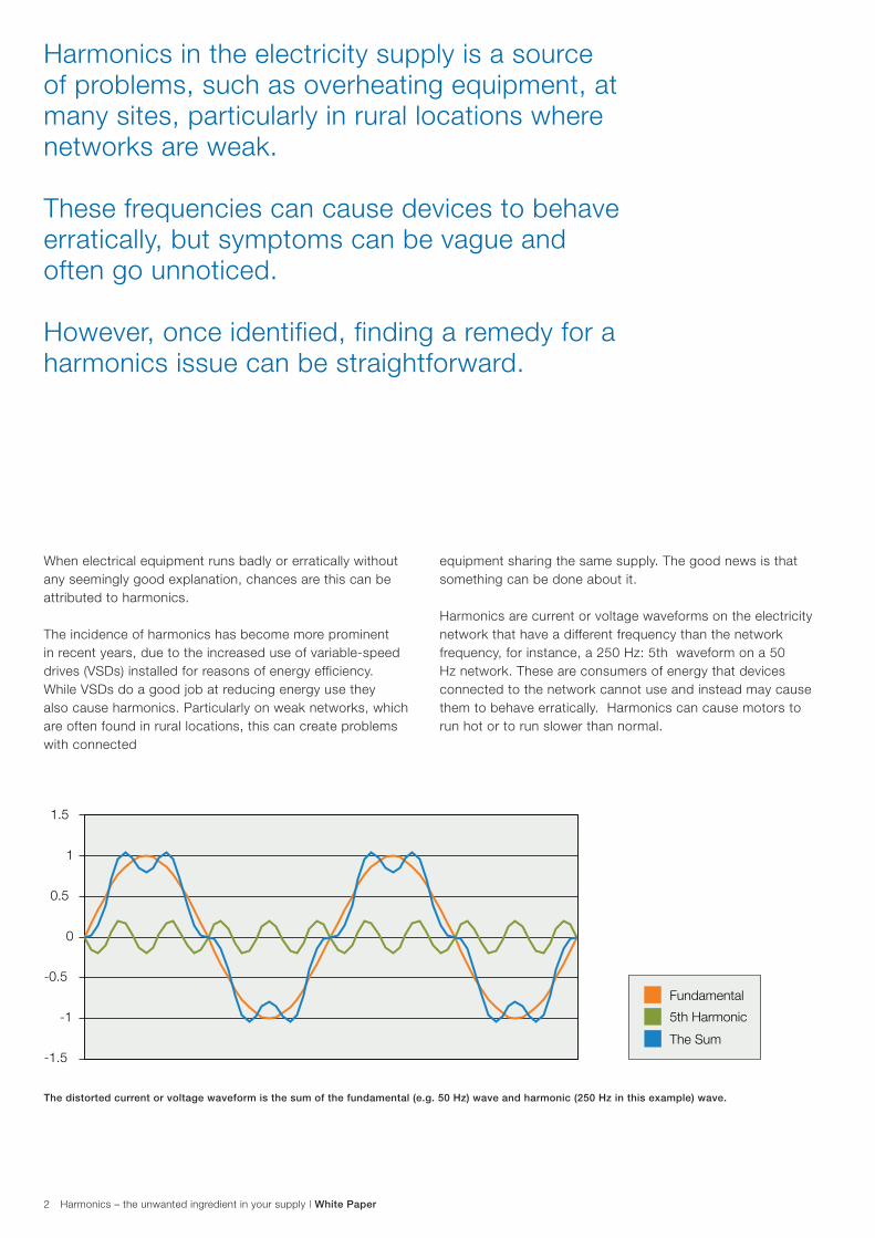
The distorted current or voltage waveform is the sum of the fundamental (e.g. 50 Hz) wave and harmonic (250 Hz in this example) wave.
equipment sharing the same supply. The good news is that something can be done about it.
Harmonics are current or voltage waveforms on the electricity network that have a different frequency than the network frequency, for instance, a 250 Hz: 5th waveform on a 50 Hz network. These are consumers of energy that devices connected to the network cannot use and instead may cause them to behave erratically. Harmonics can cause motors to run hot or to run slower than normal.
1.5
1
0.5
0
-0.5
-1
-1.5
Fundamental
The Sum
5th Harmonic
Harmonics – the unwanted ingredient in your supply | White Paper 3
Harmonic current waveforms are created by the VSD due to the conversion of the incoming AC 50 Hz waveform into a DC source for the output stage to create pulse width modulated pulses that control the AC motor. This conversion from AC to DC and then back to AC, result in current waveforms that are multiples of the network frequency.
Finding a remedyIt is not so much the harmonics themselves that cause a problem. It is more down to the fact that the associated symptoms of harmonics can be vague and mean that solutions are often sought in other areas.
Once a harmonics issue has been identified there are effective remedies available.
However, harmonics expertise can be difficult to find as most electrical engineers have had little experience in the field. When suspicions arise there may be a harmonics issue on the site, it is usually best to contact the VSD manufacturer. All harmonics problems have a cure, but the solution varies with the conditions on the site and it is important to apply the measures that will work where you are. There is no universal remedy that will solve all harmonics issues.
Harmonics mitigation techniques
There are three options when working with harmonics - reduction, cancellation or diversion. Reduction is achieved by added inductance or an active rectifier; cancellation by a 12- or 24-pulse drive or an active supply unit and integrated low harmonic line filter, or more commonly called a low harmonic VSD and diversion by a passive filter.
Reduction The most basic technique is to use AC line reactors, usually known as chokes, fitted inside or outside the drive. With a correctly sized AC/DC choke in an ordinary six-pulse drive, harmonics levels can be substantially reduced. The objective is to reduce harmonics to a level where they no longer cause a problem. Another approach to reduction is to use an active rectifier. This has an inverter working “backwards” onto the mains supply, treating the mains supply as it would treat an electric motor and mitigating the incoming wave
Cancellation Cancellation has traditionally been achieved by using a 12 or 24 pulse drive. Total harmonic load is divided between several isolated sources sharing a common primary supply (via an input transformer). A 12-pulse drive uses two sources, with each source phase-shifted by 30 degrees
relative to the other. A 24-pulse drive uses four sources shifted 15 degrees relative to the other. A more modern approach is either to use an low harmonic VSD or a closed loop Active Filter.
A low harmonic VSD uses an insulated-gate bipolar transistor (IGBT) input bridge and cancels the harmonics within the VSD system in the first place.
An closed loop active filter injects a ‘anti’ harmonic current spectrum that sums to zero (or client specific values) with the load harmonic currents; leaving a ‘clean’ current on the mains supply
12 and 24 pulse drives tend only to be used these days if the required transformers are already on-site or a new installation requires a dedicated transfer per VSD for powers over 500kW.
Diversion The passive filter works by diverting harmonics away from the affected equipment, but it is a fairly inflexible solution with few application areas and it has several drawbacks.
For instance, it increases voltage and heat loss and reduces power factor. At low fundamental load (25Hz load) it requires capacitor disconnect to protect its capacitors against over-
voltage, which means no protection is offered at low speed. When reconnecting, there is a time delay for capacitor discharge, which means this method is unsuitable for cyclical control. If used with a generator supply, the sudden disconnection can cause unacceptable harmonic levels on the network. The filter is also likely to import background harmonics from the network which increases total harmonics. Some harmonic frequencies are difficult to address with a passive filter and are likely to remain. All these issues combined increase the heat loss of the active filter.
Bearing in mind its limitations – and we still haven’t mentioned all of them – the passive filter requires a number of fairly complicated calculations to be used successfully. Still, if the conditions are met, it can provide a cost-effective alternative. The problem arises when vendors that do not have a full range of harmonics mitigating equipment try to sell passive filters for applications where they are not suitable.
All these measures can be applied on both low voltage and medium voltage networks. However, mitigation of harmonics on a medium voltage network can be quite costly. It is often more cost-effective to correct on the low voltage side.
Three ways to approach harmonics
Harmonics – the unwanted ingredient in your supply | White Paper 4
Some level of harmonics on the network are acceptable and to eliminate them completely would not be practicable.
The issue is to find out at what level for a particular site is an acceptable condition. A particular VSD configuration can work perfectly well at some sites, while exactly the same setup can cause substantial problems elsewhere.
This difference is down to the network.
A weak network has a low fault level and will be more susceptible to harmonics. Fault levels differ widely depending on the type of earth system used, the supply type and the proximity to the supply.
Unfortunately, there is no way of knowing, without prior installation, what the fault level will be. It is possible to have a harmonic survey done at the site, but if awareness of the issue is low in the first place, this is unlikely to happen.
It is also important to bear in mind that all VSDs are not the same. Some will cause more than double the amount of harmonic distortion compared to others. Performance values will be different within one manufacturers different product ranges let alone comparisons between different manufacturers.
The amount of harmonic distortion is mitigated by chokes (or choice of supply bridge) in a drive; more chokes - more heat, which means all components have to be larger and more robust, in turn reflected in the price. So the chances are that cheap drives (reduced choke size or diode bridge designs) will cause more harmonics than higher priced ones.
Once harmonics have been identified, there are plenty of remedies. The main challenge is to identify the problem in the first place, especially where symptoms of harmonics are often mistakenly believed to have some other cause. Incorrect remedial action further disguises the fundamental issue. When in doubt, always discuss the issue with a reputable VSD manufacturer.
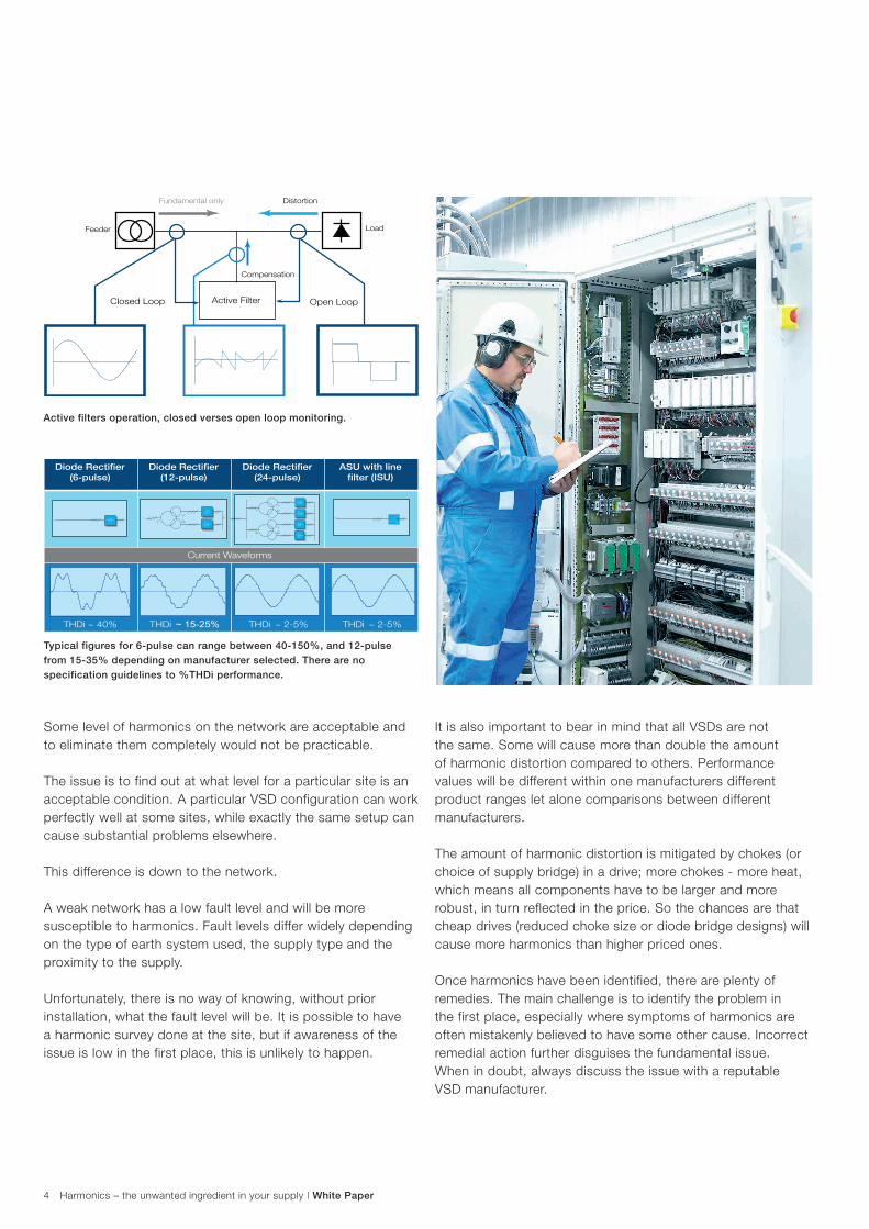
Active Filter Open Loop Closed Loop
Compensation
Fundamental only
- 1 . 3
1 . 3
0 3 6 0
-1.3
1.3
0
360
Feeder Load
-1.3
0360
1.3
Distortion
Diode Rectifier (6-pulse)
Diode Rectifier (12-pulse)
Diode Rectifier (24-pulse)
ASU with line filter (ISU)
Current Waveforms
THDi ~ 40%
THDi ~ 15-25%
THDi ~ 2-5%
THDi ~ 2-5%
3 ~ 3 ~ 3~ 3 ~
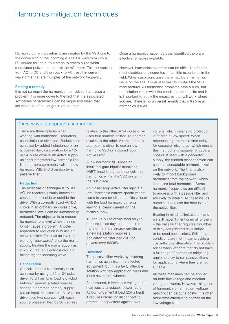
Active filters operation, closed verses open loop monitoring.
Typical figures for 6-pulse can range between 40-150%, and 12-pulse from 15-35% depending on manufacturer selected. There are no specification guidelines to %THDi performance.

Contact us
Har
mon
ics
– th
e un
wan
ted
ingr
edie
nt in
you
r su
pply
/ W
hite
Pap
er /
Aug
201
4 Notes: We reserve the right to make technical changes or modify the contents of this document without prior notice. With regard to purchase orders, the agreed particulars shall prevail. ABB does not accept any responsibility whatsoever for potential errors or possible lack of information in this document.
We reserve all rights in this document and in the subject matter and illustrations contained therein. Any reproduction, disclosure to third parties or utilization of its contents – in whole or in parts – is forbidden without prior written consent of ABB.
Copyright© 2014 ABB
All rights reserved
ABB LimitedDaresbury ParkDaresburyWarringtonCheshireWA4 4BTTel: +44 (0) 1925 741 111Fax: +44 (0) 1925 741 212
www.abb.co.uk/energy


![Current Harmonic Estimation in Power Transmission Lines ... · The unwanted harmonics generated by nonlinear loads or devices yield many problems in power systems [1]. Technical solutions](https://img.pdfslide.us/doc/110x75/6041501e2fd87071c678ff84/current-harmonic-estimation-in-power-transmission-lines-the-unwanted-harmonics.jpg)