Embed Size (px)
Citation preview
W H I T E P A P E R
te.com/products/magnet-wire© 2011 Tyco Electronics Corporation. All Rights Reserved. | MAG-MATE, TE Connectivity, TE connectivity (logo) and TE (logo) are trademarks of the TE Connectivity Ltd family of companies. Other logos, product and Company names
mentioned herein may be trademarks of their respective owners.
The switch to aluminum magnet wire is on the
agenda of electric motor manufacturers
Many fractional horse power (FHP) motor manufacturers,
selling to the appliance, heating, ventilation, and
air conditioning equipment industries, are seriously
evaluating a switch from copper to aluminum magnet
wire. The economics of switching to aluminum are quite
straightforward: Copper magnet wire currently contributes
up to ten percent to the overall cost of a typical FHP electric
motor. At current market prices, switching from copper to
aluminum wire can potentially reduce this contribution to
less than two percent.
However, to achieve equal conductivity, aluminum wire needs
to have a larger cross-sectional area than copper. As a rule
the AWG* has to be reduced by two numbers which means
that, for instance, a 20 AWG copper wire could be replaced
by 18 AWG aluminum wire. Yet, even on an equal conductivity
basis, aluminum is one half the weight of copper. For medium
and high volume FHP motor manufacturers in particular
the reduced material cost and the lower motor weight are
equally welcome. Looking at the price development, it also
appears that aluminum is not subject to the same price
increase that can be seen with copper.
Applying MAG-MATE Insulation Displacement
Connection (IDC) Technology to Aluminum
Magnet Wire Applications
D A R M S TA D T, G E R M A N Y | J U N E 2 0 1 1
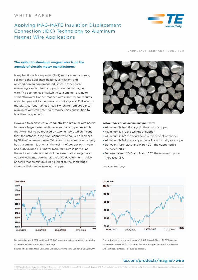
Between January 1, 2010 and March 31, 2011 aluminum prices increased by roughly
14 percent at the London Metal Exchange.
Source: The London Metal Exchange Limited, www.lme.com, London, EC3A 2DX, UK
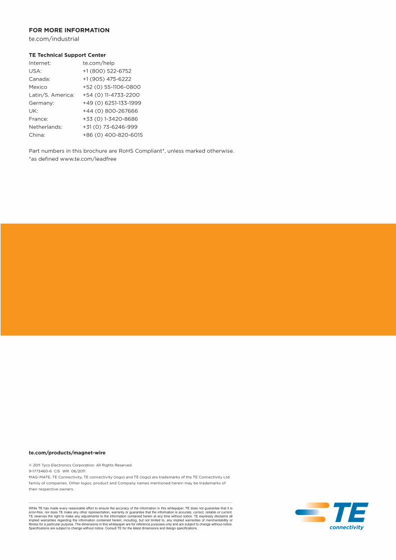
During the same time span (January 1, 2010 through March 31, 2011) copper
rocketed to above 10,000 USD/ton, before it dropped to around 9,500 USD,
which still is an increase of over 25 percent.
Advantages of aluminum magnet wire:
• Aluminum is traditionally 1/4 the cost of copper
• Aluminum is 1/3 the weight of copper
• Aluminum is 1/2 the equal conductive weight of copper
• Aluminum is 1/8 the cost per unit of conductivity vs. copper
• Between March 2010 and March 2011 the copper price
increased 30 %
• Between March 2010 and March 2011 the aluminum price
increased 12 %
*American Wire Gauge
W H I T E P A P E R
te.com/products/magnet-wire5
© 2011 Tyco Electronics Corporation. All Rights Reserved. | MAG-MATE, TE Connectivity, TE connectivity (logo) and TE (logo) are trademarks of the TE Connectivity Ltd family of companies. Other logos, product and Company names
mentioned herein may be trademarks of their respective owners.
Initiale T-rise #1Tempera-ture Life
Humidity-Temp
Cycling
Thermal Shock
Vibration Axis #1
Vibration Axis #2
Vibration Axis #3
Vibration Axis #4
Vibration Axis #5
Vibration Axis #6
Group 1 5.8845 5.96475 5.92725 5.8795 5.927 5.9245 5.93675 5.91575 5.92925 5.941 5.942
Group 2 5.888 5.9485 5.929 5.86775 5.9465 5.95725 5.969 5.942 5.94075 5.94475 5.953
Group 3 5.77975 5.861 5.83325 5.771 6.14625 6.213 6.251 6.23225 6.243 6.259 6.2695
Group 4 5.8135 5.88475 5.863 5.84575 6.648 6.722667 6.808667 6.958 7.246 8.243 9.956667
Group 5 3.834 3.88825 3.8815 3.85625 3.88375 3.89675 3.89625 3.8935 3.876 3.8785 3.882
Figure 3:
Average resistance levels of the MAG-MATE
terminal on aluminum wire, and subjected to
environmental and mechanical stresses.
Figure 4:
Average resistance levels of standard and
modified MAG-MATE terminals to aluminum
magnet wire.
Table 2:
Parameters for testing redesigned IDC
terminals for aluminum.
Group Wire size Beam design Plating Strain relief
1 #21 AWG Al More Compliant Beam Indium Standard
2 #21 AWG Al More Compliant Beam Tin Standard
3 #21 AWG Al Standard Beam Indium Standard
4 #21 AWG Al Standard Beam Tin Standard
5 #21 AWG Al More Compliant Beam Indium Enhanced
6 #21 AWG Al More Compliant Beam Tin Enhanced
7 #21 AWG Al Standard Beam Indium Enhanced
8 #21 AWG Al Standard Beam Tin Enhanced
27.5
25
22.5
20
17.5
15
12.5
10
7.5
5
10.5
9.5
8.5
7.5
6.5
5.5
4.5
3.5
Mil
lio
hm
sM
illi
oh
ms
Initiale T-rise #1Tempera-ture Life
Humidity-Temp
Cycling
Thermal Shock
Vibration Axis #1
Vibration Axis #2
Vibration Axis #3
Final T-Rise
Group 1 6.758 7.071 8.023 10.307 11.192 12.14 12.852 13.513 16.57
Group 2 6.263 6.534 6.633 6.736 6.818 6.848 6.951 7.095 7.463
Group 3 5.924 5.933 6.074 6.184 6.231 6.257 6.239 6.235 6.261
Group 4 5.893 5.887 5.906 5.918 5.958 5.974 5.963 5.952 5.987
Group 5 6.941 7.234 8.239 10.401 12.987 20.872 22.601 22.08 25.026
Group 6 6.467 6.499 6.569 6.615 6.843 6.928 7.023 7.125 7.277
Group 7 5.94 5.943 6.078 6.457 7.535 8.21 8.41 8.443 8.47
Group 8 5.877 5.874 5.887 5.886 5.932 5.918 5.92 5.9 5.925
FOR MORE INFORMATION
te.com/industrial
TE Technical Support Center
Internet: te.com/help
USA: +1 (800) 522-6752
Canada: +1 (905) 475-6222
Mexico +52 (0) 55-1106-0800
Latin/S. America: +54 (0) 11-4733-2200
Germany: +49 (0) 6251-133-1999
UK: +44 (0) 800-267666
France: +33 (0) 1-3420-8686
Netherlands: +31 (0) 73-6246-999
China: +86 (0) 400-820-6015
Part numbers in this brochure are RoHS Compliant*, unless marked otherwise.
*as defined www.te.com/leadfree
te.com/products/magnet-wire
© 2011 Tyco Electronics Corporation. All Rights Reserved.
9-1773460-6 CIS WR 06/2011
MAG-MATE, TE Connectivity, TE connectivity (logo) and TE (logo) are trademarks of the TE Connectivity Ltd
family of companies. Other logos, product and Company names mentioned herein may be trademarks of
their respective owners.
While TE has made every reasonable effort to ensure the accuracy of the information in this whitepaper, TE does not guarantee that it is error-free, nor does TE make any other representation, warranty or guarantee that the information is accurate, correct, reliable or current. TE reserves the right to make any adjustments to the information contained herein at any time without notice. TE expressly disclaims all implied warranties regarding the information contained herein, including, but not limited to, any implied warranties of merchantability or fitness for a particular purpose. The dimensions in this whitepaper are for reference purposes only and are subject to change without notice. Specifications are subject to change without notice. Consult TE for the latest dimensions and design specifications.

te.com/products/magnet-wire2
© 2011 Tyco Electronics Corporation. All Rights Reserved. | MAG-MATE, TE Connectivity, TE connectivity (logo) and TE (logo) are trademarks of the TE Connectivity Ltd family of companies. Other logos, product and Company names
mentioned herein may be trademarks of their respective owners.
W H I T E P A P E R
Wire connection technology has to be on a par with
the reliability of copper-based interconnection
The major obstacle to benefiting from the huge potential
cost savings has always been finding a way to make
electro-mechanical connections to aluminum magnet wire
at production and reliability levels equal to that of copper
magnet wire. This paper takes an in-depth look at the
above opportunities and obstacles and offers solutions to
reconcile the two. As aluminum is more brittle than copper,
the interconnection needs to be adjusted for its different
material properties. Still, the termination technology needs
to be fast, efficient, durable and repeat-accurate which more
or less excludes sonic welding or soldering from the list of
options for medium to large volume production.
IDC Technology
TE Connectivity (TE) has been successfully driving a superior
solution for magnet wire termination over the past 15 years:
Many leading FHP motor and pump manufacturers around
the world use TE’s MAG-MATE product range to terminate
copper magnet wire. This product portfolio is based on
Insulation Displacement Connection (IDC) technology. IDC
has proven to be an effective alternative to stripping and
soldering wire in thousands of applications for over 40 years.
Originally the IDC principle provided an effective
way to terminate stranded and solid lead wire in the
telecommunications industry. Increasing demand for cost
reductions in the highly competitive FHP market eventually
drove the transfer of IDC technology into these and other
magnet wire applications. To meet this demand,
TE developed the MAG-MATE IDC interconnection system,
which comprises efficient and durable termination products
for medium and high volume manufacturing operations. In
total the MAG-MATE product portfolio covers a wide range
of wire gauges and offers a multitude of possible terminal
contact geometries. For applications with space constraints
slim-line and mini solutions offer an efficient termination
option.
How MAG-MATE IDC technology works
In the IDC-based interconnection system, box-shaped
dual-beam terminals reside on a continuous strip. The
manufacturer inserts the terminals into a plastic cavity using
either semi or fully automatic insertion equipment. The
plastic cavity can be molded onto the customer’s existing
bobbin or can be part of a separately attached housing.
This molded cavity has two slots at opposing sides with a
chamfered lead-in at the top of each slot. The magnet wire
from the bobbin is pre-positioned into these two slots either
manually or by the winding equipment. The wire is supported
inside the cavity by means of an integral wire support or
"anvil" feature.
The MAG-MATE metal terminal has two IDC slots with
chamfered lead-ins at the slot entrances. The terminal is
positioned over the magnet wire in the housing cavity
and inserted. Specially designed terminal features, called
"nickers", clean the insulation film from the wire surface
during insertion. Once the terminal is fully seated, the wire
is captured within the two insulation displacement slots to
provide a reliable termination, Figure 1. The wire deforms to
an oblong shape. During this process four gas-tight points of
contact (two on each beam) are created between the wire
and terminal. The opposing side walls of each terminal slot
have residual spring energy that maintains constant pressure
on the wire, providing a reliable, long-term connection.
Similarly, the molded plastic slots grip the wire on each side
of the metal terminal, providing strain relief.
Figure 1:
The IDC termination process. When the magnet wire from the bobbin is
pre-positioned into the slots of the plastic cavity, the MAG-MATE terminal is
inserted into the cavity. During this the insulation is displaced from the wire
surface. The stripped wire deforms to an oblong shape, creating four gas-tight
points of contact.
Table 1:
The test samples covered three options for the wire insertion depth, and showed
the influence of a strain relief feature.
W H I T E P A P E R W H I T E P A P E R
te.com/products/magnet-wire te.com/products/magnet-wire3 4
© 2011 Tyco Electronics Corporation. All Rights Reserved. | MAG-MATE, TE Connectivity, TE connectivity (logo) and TE (logo) are trademarks of the TE Connectivity Ltd family of companies. Other logos, product and Company names
mentioned herein may be trademarks of their respective owners.
© 2011 Tyco Electronics Corporation. All Rights Reserved. | MAG-MATE, TE Connectivity, TE connectivity (logo) and TE (logo) are trademarks of the TE Connectivity Ltd family of companies. Other logos, product and Company names
mentioned herein may be trademarks of their respective owners.
Figure 3 compares the average resistance levels of the
MAG-MATE terminal on aluminum wire and subjected to
environmental and mechanical stresses. Some samples
provided strain relief by means of an interference fit between
the magnet wire and plastic cavity slots. Other samples
did not incorporate the strain relief feature. One test group
included copper magnet wire as a base line for comparison.
Evaluating the possible influence of connector
design modifications
Analysis of the influence of the wire end position revealed
just how important the resilience and long-term pre-loading
of the IDC slot beams are for mechanical durability. But what
about the electric properties of the interconnection? Would
changes in the IDC design improve e.g. resistance? Figure
4 shows a similar comparison of average resistance levels
of standard and modified MAG-MATE terminals used with
aluminum magnet wire. In this case the groups represent
different combinations of slot designs, plating materials,
and strain relief, as indicated in Table 2. Indium plating was
selected due to its ability to inhibit aluminum oxides.
Results show that the standard connector design (Group 4)
offers the best performance. Special indium plating actually
diminished termination performance on aluminum magnet
wire. The combination of a more compliant slot with the
special plating (Group 1) clearly produced unstable
terminations. Additionally, enhanced strain relief offered no
improvement over a standard interference fit between the
magnet wire and the slot in the plastic cavity.
We therefore conclude that the standard MAG-MATE
terminal with the wire terminated in the compliant region of
the slot and standard strain relief from the plastic cavity offer
the best performance for aluminum magnet wire.
Conclusion
These TE studies indicate that FHP motor manufacturers
can switch from copper to aluminum magnet wire and use
standard insulation displacement terminals to eliminate labor
intensive pre-stripping or soldering.
In order to ensure that the termination process leaves
the wire in a compliant region of the connector slot, the
TE engineering team will specify an optimum insertion
depth for an application. In addition to that, a strain relief
mechanism is required. However, tests have shown that the
interference fit between magnet wire and plastic cavity
slot can provide an adequate solution. Finally, TE does
not recommend the use of single-beam IDC terminals for
aluminum magnet wire terminations because they do not
provide the robustness and control needed for such a
dynamic conductor as aluminum wire.
Customers considering replacing copper magnet wire by
aluminum wire are welcome to contact TE engineering for
design-in support. Based on 15 years of experience with
IDC interconnection technology for magnet wire, and the
portrayed in-house studies, TE can optimally apply the
principal benefits of IDC technology to aluminum magnet
wire termination.
Figure 2:
Testing the possible insertion depth levels
A, B, and C revealed the influence of the
wire end position on the termination life.
Terminating aluminum magnet wire
The termination of aluminum magnet wire has presented
unique challenges for IDC technology. Environmental and
mechanical stresses will cause aluminum to experience creep
and stress relaxation to a much higher degree than copper.
Magnet wire manufacturers have been able to minimize
the creep and stress relaxation characteristics by alloying
aluminum magnet wire with iron, but at a higher cost than
traditional aluminum wire. Instead, the MAG-MATE IDC
termination can be designed to compensate for the material
properties of aluminum without impacting the aluminum
alloy price, the wire weight – or the termination quality itself.
Therefore TE conducted studies to verify the factors that
result in long-term successful IDC termination of aluminum
magnet wire. These studies incorporated environmental and
mechanical stresses and evaluated the effects of:
• Wire position within IDC slot
• IDC slot compliance
• Terminal plating materials
• Strain relief features
The tests showed a very stable performance of MAG-MATE
terminals on aluminum magnet wire as long as manufacturers
take certain precautions during the termination process.
To ensure a successful termination on aluminum wire, the
manufacturer:
• must not over-insert the wire into the IDC slots.
• must incorporate strain relief features in the plastic housing.
Details on the influence of the wire end position
Table 1 and Figure 2 both illustrate different test samples,
grouped according to the depth of wire insertion (ranging
from A to C), and the presence or absence of a strain
relief feature. Wire end position "A" is the most compliant,
providing maximum springback capability and longest
termination life on aluminum magnet wire. Wire end position
"B" is the standard wire insertion depth used with copper,
which results into normal springback capabilities and
termination life.
Group Wire size, material Wire position in slot
Strain relief?
1 #21 AWG Al A Yes
2 #21 AWG Al A No
3 #21 AWG Al C Yes
4 #21 AWG Al C No
5 #21 AWG Cu B Yes
Wire end position "C" proved to be the least compliant,
providing virtually no springback and leading to a short
termination life on aluminum magnet wire. Test data
for groups 3 and 4 shown in Table 1 illustrate that over-
insertion of the magnet wire into the IDC slot compromises
the successful termination of aluminum magnet wire. The
absence of a strain relief feature (Group 4) significantly
increases the instability of the termination. As a result, TE
Connectivity now specifies an optimal insertion depth for
the terminal, measured from the top of the plastic cavity
to the top of the terminal. This assures proper aluminum
wire placement and eliminates the need for destructive
inspection.

W H I T E P A P E R
te.com/products/magnet-wire© 2011 Tyco Electronics Corporation. All Rights Reserved. | MAG-MATE, TE Connectivity, TE connectivity (logo) and TE (logo) are trademarks of the TE Connectivity Ltd family of companies. Other logos, product and Company names
mentioned herein may be trademarks of their respective owners.
The switch to aluminum magnet wire is on the
agenda of electric motor manufacturers
Many fractional horse power (FHP) motor manufacturers,
selling to the appliance, heating, ventilation, and
air conditioning equipment industries, are seriously
evaluating a switch from copper to aluminum magnet
wire. The economics of switching to aluminum are quite
straightforward: Copper magnet wire currently contributes
up to ten percent to the overall cost of a typical FHP electric
motor. At current market prices, switching from copper to
aluminum wire can potentially reduce this contribution to
less than two percent.
However, to achieve equal conductivity, aluminum wire needs
to have a larger cross-sectional area than copper. As a rule
the AWG* has to be reduced by two numbers which means
that, for instance, a 20 AWG copper wire could be replaced
by 18 AWG aluminum wire. Yet, even on an equal conductivity
basis, aluminum is one half the weight of copper. For medium
and high volume FHP motor manufacturers in particular
the reduced material cost and the lower motor weight are
equally welcome. Looking at the price development, it also
appears that aluminum is not subject to the same price
increase that can be seen with copper.
Applying MAG-MATE Insulation Displacement
Connection (IDC) Technology to Aluminum
Magnet Wire Applications
D A R M S TA D T, G E R M A N Y | J U N E 2 0 1 1
Between January 1, 2010 and March 31, 2011 aluminum prices increased by roughly
14 percent at the London Metal Exchange.
Source: The London Metal Exchange Limited, www.lme.com, London, EC3A 2DX, UK
During the same time span (January 1, 2010 through March 31, 2011) copper
rocketed to above 10,000 USD/ton, before it dropped to around 9,500 USD,
which still is an increase of over 25 percent.
Advantages of aluminum magnet wire:
• Aluminum is traditionally 1/4 the cost of copper
• Aluminum is 1/3 the weight of copper
• Aluminum is 1/2 the equal conductive weight of copper
• Aluminum is 1/8 the cost per unit of conductivity vs. copper
• Between March 2010 and March 2011 the copper price
increased 30 %
• Between March 2010 and March 2011 the aluminum price
increased 12 %
*American Wire Gauge
W H I T E P A P E R
te.com/products/magnet-wire5
© 2011 Tyco Electronics Corporation. All Rights Reserved. | MAG-MATE, TE Connectivity, TE connectivity (logo) and TE (logo) are trademarks of the TE Connectivity Ltd family of companies. Other logos, product and Company names
mentioned herein may be trademarks of their respective owners.
Initiale T-rise #1Tempera-ture Life
Humidity-Temp
Cycling
Thermal Shock
Vibration Axis #1
Vibration Axis #2
Vibration Axis #3
Vibration Axis #4
Vibration Axis #5
Vibration Axis #6
Group 1 5.8845 5.96475 5.92725 5.8795 5.927 5.9245 5.93675 5.91575 5.92925 5.941 5.942
Group 2 5.888 5.9485 5.929 5.86775 5.9465 5.95725 5.969 5.942 5.94075 5.94475 5.953
Group 3 5.77975 5.861 5.83325 5.771 6.14625 6.213 6.251 6.23225 6.243 6.259 6.2695
Group 4 5.8135 5.88475 5.863 5.84575 6.648 6.722667 6.808667 6.958 7.246 8.243 9.956667
Group 5 3.834 3.88825 3.8815 3.85625 3.88375 3.89675 3.89625 3.8935 3.876 3.8785 3.882
Figure 3:
Average resistance levels of the MAG-MATE
terminal on aluminum wire, and subjected to
environmental and mechanical stresses.
Figure 4:
Average resistance levels of standard and
modified MAG-MATE terminals to aluminum
magnet wire.
Table 2:
Parameters for testing redesigned IDC
terminals for aluminum.
Group Wire size Beam design Plating Strain relief
1 #21 AWG Al More Compliant Beam Indium Standard
2 #21 AWG Al More Compliant Beam Tin Standard
3 #21 AWG Al Standard Beam Indium Standard
4 #21 AWG Al Standard Beam Tin Standard
5 #21 AWG Al More Compliant Beam Indium Enhanced
6 #21 AWG Al More Compliant Beam Tin Enhanced
7 #21 AWG Al Standard Beam Indium Enhanced
8 #21 AWG Al Standard Beam Tin Enhanced
27.5
25
22.5
20
17.5
15
12.5
10
7.5
5
10.5
9.5
8.5
7.5
6.5
5.5
4.5
3.5
Mil
lio
hm
sM
illi
oh
ms
Initiale T-rise #1Tempera-ture Life
Humidity-Temp
Cycling
Thermal Shock
Vibration Axis #1
Vibration Axis #2
Vibration Axis #3
Final T-Rise
Group 1 6.758 7.071 8.023 10.307 11.192 12.14 12.852 13.513 16.57
Group 2 6.263 6.534 6.633 6.736 6.818 6.848 6.951 7.095 7.463
Group 3 5.924 5.933 6.074 6.184 6.231 6.257 6.239 6.235 6.261
Group 4 5.893 5.887 5.906 5.918 5.958 5.974 5.963 5.952 5.987
Group 5 6.941 7.234 8.239 10.401 12.987 20.872 22.601 22.08 25.026
Group 6 6.467 6.499 6.569 6.615 6.843 6.928 7.023 7.125 7.277
Group 7 5.94 5.943 6.078 6.457 7.535 8.21 8.41 8.443 8.47
Group 8 5.877 5.874 5.887 5.886 5.932 5.918 5.92 5.9 5.925
FOR MORE INFORMATION
te.com/industrial
TE Technical Support Center
Internet: te.com/help
USA: +1 (800) 522-6752
Canada: +1 (905) 475-6222
Mexico +52 (0) 55-1106-0800
Latin/S. America: +54 (0) 11-4733-2200
Germany: +49 (0) 6251-133-1999
UK: +44 (0) 800-267666
France: +33 (0) 1-3420-8686
Netherlands: +31 (0) 73-6246-999
China: +86 (0) 400-820-6015
Part numbers in this brochure are RoHS Compliant*, unless marked otherwise.
*as defined www.te.com/leadfree
te.com/products/magnet-wire
© 2011 Tyco Electronics Corporation. All Rights Reserved.
9-1773460-6 CIS WR 06/2011
MAG-MATE, TE Connectivity, TE connectivity (logo) and TE (logo) are trademarks of the TE Connectivity Ltd
family of companies. Other logos, product and Company names mentioned herein may be trademarks of
their respective owners.
While TE has made every reasonable effort to ensure the accuracy of the information in this whitepaper, TE does not guarantee that it is error-free, nor does TE make any other representation, warranty or guarantee that the information is accurate, correct, reliable or current. TE reserves the right to make any adjustments to the information contained herein at any time without notice. TE expressly disclaims all implied warranties regarding the information contained herein, including, but not limited to, any implied warranties of merchantability or fitness for a particular purpose. The dimensions in this whitepaper are for reference purposes only and are subject to change without notice. Specifications are subject to change without notice. Consult TE for the latest dimensions and design specifications.
W H I T E P A P E R
te.com/products/magnet-wire© 2011 Tyco Electronics Corporation. All Rights Reserved. | MAG-MATE, TE Connectivity, TE connectivity (logo) and TE (logo) are trademarks of the TE Connectivity Ltd family of companies. Other logos, product and Company names
mentioned herein may be trademarks of their respective owners.
The switch to aluminum magnet wire is on the
agenda of electric motor manufacturers
Many fractional horse power (FHP) motor manufacturers,
selling to the appliance, heating, ventilation, and
air conditioning equipment industries, are seriously
evaluating a switch from copper to aluminum magnet
wire. The economics of switching to aluminum are quite
straightforward: Copper magnet wire currently contributes
up to ten percent to the overall cost of a typical FHP electric
motor. At current market prices, switching from copper to
aluminum wire can potentially reduce this contribution to
less than two percent.
However, to achieve equal conductivity, aluminum wire needs
to have a larger cross-sectional area than copper. As a rule
the AWG* has to be reduced by two numbers which means
that, for instance, a 20 AWG copper wire could be replaced
by 18 AWG aluminum wire. Yet, even on an equal conductivity
basis, aluminum is one half the weight of copper. For medium
and high volume FHP motor manufacturers in particular
the reduced material cost and the lower motor weight are
equally welcome. Looking at the price development, it also
appears that aluminum is not subject to the same price
increase that can be seen with copper.
Applying MAG-MATE Insulation Displacement
Connection (IDC) Technology to Aluminum
Magnet Wire Applications
D A R M S TA D T, G E R M A N Y | J U N E 2 0 1 1
Between January 1, 2010 and March 31, 2011 aluminum prices increased by roughly
14 percent at the London Metal Exchange.
Source: The London Metal Exchange Limited, www.lme.com, London, EC3A 2DX, UK
During the same time span (January 1, 2010 through March 31, 2011) copper
rocketed to above 10,000 USD/ton, before it dropped to around 9,500 USD,
which still is an increase of over 25 percent.
Advantages of aluminum magnet wire:
• Aluminum is traditionally 1/4 the cost of copper
• Aluminum is 1/3 the weight of copper
• Aluminum is 1/2 the equal conductive weight of copper
• Aluminum is 1/8 the cost per unit of conductivity vs. copper
• Between March 2010 and March 2011 the copper price
increased 30 %
• Between March 2010 and March 2011 the aluminum price
increased 12 %
*American Wire Gauge
W H I T E P A P E R
te.com/products/magnet-wire5
© 2011 Tyco Electronics Corporation. All Rights Reserved. | MAG-MATE, TE Connectivity, TE connectivity (logo) and TE (logo) are trademarks of the TE Connectivity Ltd family of companies. Other logos, product and Company names
mentioned herein may be trademarks of their respective owners.
Initiale T-rise #1Tempera-ture Life
Humidity-Temp
Cycling
Thermal Shock
Vibration Axis #1
Vibration Axis #2
Vibration Axis #3
Vibration Axis #4
Vibration Axis #5
Vibration Axis #6
Group 1 5.8845 5.96475 5.92725 5.8795 5.927 5.9245 5.93675 5.91575 5.92925 5.941 5.942
Group 2 5.888 5.9485 5.929 5.86775 5.9465 5.95725 5.969 5.942 5.94075 5.94475 5.953
Group 3 5.77975 5.861 5.83325 5.771 6.14625 6.213 6.251 6.23225 6.243 6.259 6.2695
Group 4 5.8135 5.88475 5.863 5.84575 6.648 6.722667 6.808667 6.958 7.246 8.243 9.956667
Group 5 3.834 3.88825 3.8815 3.85625 3.88375 3.89675 3.89625 3.8935 3.876 3.8785 3.882
Figure 3:
Average resistance levels of the MAG-MATE
terminal on aluminum wire, and subjected to
environmental and mechanical stresses.
Figure 4:
Average resistance levels of standard and
modified MAG-MATE terminals to aluminum
magnet wire.
Table 2:
Parameters for testing redesigned IDC
terminals for aluminum.
Group Wire size Beam design Plating Strain relief
1 #21 AWG Al More Compliant Beam Indium Standard
2 #21 AWG Al More Compliant Beam Tin Standard
3 #21 AWG Al Standard Beam Indium Standard
4 #21 AWG Al Standard Beam Tin Standard
5 #21 AWG Al More Compliant Beam Indium Enhanced
6 #21 AWG Al More Compliant Beam Tin Enhanced
7 #21 AWG Al Standard Beam Indium Enhanced
8 #21 AWG Al Standard Beam Tin Enhanced
27.5
25
22.5
20
17.5
15
12.5
10
7.5
5
10.5
9.5
8.5
7.5
6.5
5.5
4.5
3.5
Mil
lio
hm
sM
illi
oh
ms
Initiale T-rise #1Tempera-ture Life
Humidity-Temp
Cycling
Thermal Shock
Vibration Axis #1
Vibration Axis #2
Vibration Axis #3
Final T-Rise
Group 1 6.758 7.071 8.023 10.307 11.192 12.14 12.852 13.513 16.57
Group 2 6.263 6.534 6.633 6.736 6.818 6.848 6.951 7.095 7.463
Group 3 5.924 5.933 6.074 6.184 6.231 6.257 6.239 6.235 6.261
Group 4 5.893 5.887 5.906 5.918 5.958 5.974 5.963 5.952 5.987
Group 5 6.941 7.234 8.239 10.401 12.987 20.872 22.601 22.08 25.026
Group 6 6.467 6.499 6.569 6.615 6.843 6.928 7.023 7.125 7.277
Group 7 5.94 5.943 6.078 6.457 7.535 8.21 8.41 8.443 8.47
Group 8 5.877 5.874 5.887 5.886 5.932 5.918 5.92 5.9 5.925
FOR MORE INFORMATION
te.com/industrial
TE Technical Support Center
Internet: te.com/help
USA: +1 (800) 522-6752
Canada: +1 (905) 475-6222
Mexico +52 (0) 55-1106-0800
Latin/S. America: +54 (0) 11-4733-2200
Germany: +49 (0) 6251-133-1999
UK: +44 (0) 800-267666
France: +33 (0) 1-3420-8686
Netherlands: +31 (0) 73-6246-999
China: +86 (0) 400-820-6015
Part numbers in this brochure are RoHS Compliant*, unless marked otherwise.
*as defined www.te.com/leadfree
te.com/products/magnet-wire
© 2011 Tyco Electronics Corporation. All Rights Reserved.
9-1773460-6 CIS WR 06/2011
MAG-MATE, TE Connectivity, TE connectivity (logo) and TE (logo) are trademarks of the TE Connectivity Ltd
family of companies. Other logos, product and Company names mentioned herein may be trademarks of
their respective owners.
While TE has made every reasonable effort to ensure the accuracy of the information in this whitepaper, TE does not guarantee that it is error-free, nor does TE make any other representation, warranty or guarantee that the information is accurate, correct, reliable or current. TE reserves the right to make any adjustments to the information contained herein at any time without notice. TE expressly disclaims all implied warranties regarding the information contained herein, including, but not limited to, any implied warranties of merchantability or fitness for a particular purpose. The dimensions in this whitepaper are for reference purposes only and are subject to change without notice. Specifications are subject to change without notice. Consult TE for the latest dimensions and design specifications.