Embed Size (px)
Citation preview
WHITEPAPER
Electron-beam crosslinking technology Edition 2013
Page 3 WHITE PAPERElectron-beam crosslinking technology
Content
Introduction 4History 4
Polymer material 5
Effect of electron-beam crosslinking 5
Equipment for electron-beam crosslinking 6High voltage generator 7
Electron accelerator 7
Scanning system and window 8
Product handling system 8
Control system 8
Radiation shielding and personnel safety system 9
Process optimisation by three dimensionalcomputer simulation 10Accelerator 10
Handling 10
Applications of electron-beam crosslinked cables 11
Other applications of electron-beams 12
Properties of electron-beam crosslinkedwires and cables 13
Closing 14
Authors 14
Pictures 14
Page 4
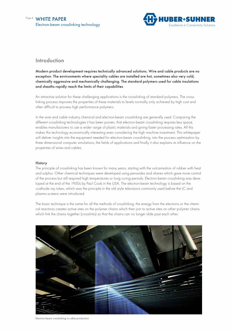
Electron-beam crosslinking in cable production
Introduction
Modern product development requires technically advanced solutions. Wire and cable products are no exception. The environments where speciality cables are installed are hot, sometimes also very cold,chemically aggressive and mechanically challenging. The standard polymers used for cable insulations and sheaths rapidly reach the limits of their capabilities
An attractive solution for these challenging applications is the crosslinking of standard polymers. The cross-linking process improves the properties of these materials to levels normally only achieved by high cost and often difficult to process high performance polymers.
In the wire and cable industry chemical and electron-beam crosslinking are generally used. Comparing the different crosslinking technologies it has been proven, that electron-beam crosslinking requires less space,enables manufacturers to use a wider range of plastic materials and giving faster processing rates. All thismakes this technology economically interesting even considering the high machine investment. This whitepaper will deliver insights into the equipment needed for electron-beam crosslinking, into the process optimisation by three dimensional computer simulations, the fields of applications and finally it also explains its influence on the properties of wires and cables.
HistoryThe principle of crosslinking has been known for many years, starting with the vulcanisation of rubber with heat and sulphur. Other chemical techniques were developed using peroxides and silanes which gave more control of the process but still required high temperatures or long curing periods. Electron-beam crosslinking was deve-loped at the end of the 1950s by Paul Cook in the USA. The electron-beam technology is based on the «cathode ray tube», which was the principle in the old style televisions commonly used before the LC andplasma screens were introduced.
The basic technique is the same for all the methods of crosslinking, the energy from the electrons or the chemi-cal reactions creates active sites on the polymer chains which then join to active sites on other polymer chains which link the chains together (crosslinks) so that the chains can no longer slide past each other.
WHITE PAPERElectron-beam crosslinking technology
Page 5
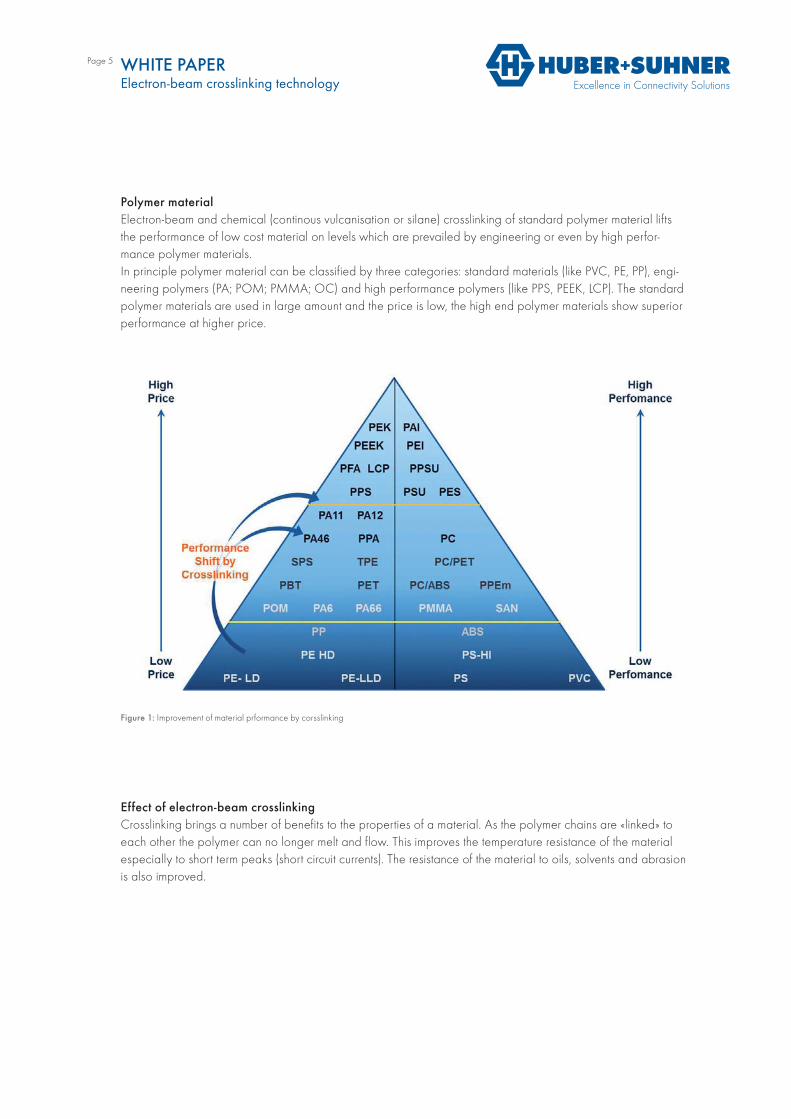
Polymer materialElectron-beam and chemical (continous vulcanisation or silane) crosslinking of standard polymer material lifts the performance of low cost material on levels which are prevailed by engineering or even by high perfor-mance polymer materials.In principle polymer material can be classified by three categories: standard materials (like PVC, PE, PP), engi-neering polymers (PA; POM; PMMA; OC) and high performance polymers (like PPS, PEEK, LCP). The standard polymer materials are used in large amount and the price is low, the high end polymer materials show superior performance at higher price.
Effect of electron-beam crosslinkingCrosslinking brings a number of benefits to the properties of a material. As the polymer chains are «linked» to each other the polymer can no longer melt and flow. This improves the temperature resistance of the material especially to short term peaks (short circuit currents). The resistance of the material to oils, solvents and abrasion is also improved.
Figure 1: Improvement of material prformance by corsslinking
WHITE PAPERElectron-beam crosslinking technology
Page 6
Equipment for electron-beam crosslinking
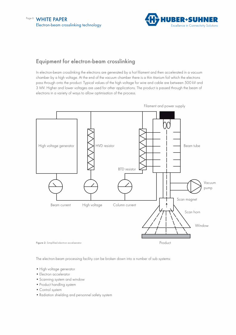
In electron-beam crosslinking the electrons are generated by a hot filament and then accelerated in a vacuum chamber by a high voltage. At the end of the vacuum chamber there is a thin titanium foil which the electrons pass through onto the product. Typical values of the high voltage for wire and cable are between 500 kV and 3 MV. Higher and lower voltages are used for other applications. The product is passed through the beam of electrons in a variety of ways to allow optimisation of the process.
The electron-beam processing facility can be broken down into a number of sub systems:
• High voltage generator• Electron accelerator• Scanning system and window• Product handling system• Control system• Radiation shielding and personnel safety system
WHITE PAPERElectron-beam crosslinking technology
Figure 2: Simplified electron accelaerator
Filament and power supply
Beam tubeHVD resistorHigh voltage generator
Beam current High voltage Column current
BTD resistor
Vacuum pump
Scan magnet
Scan horn
Window
Product
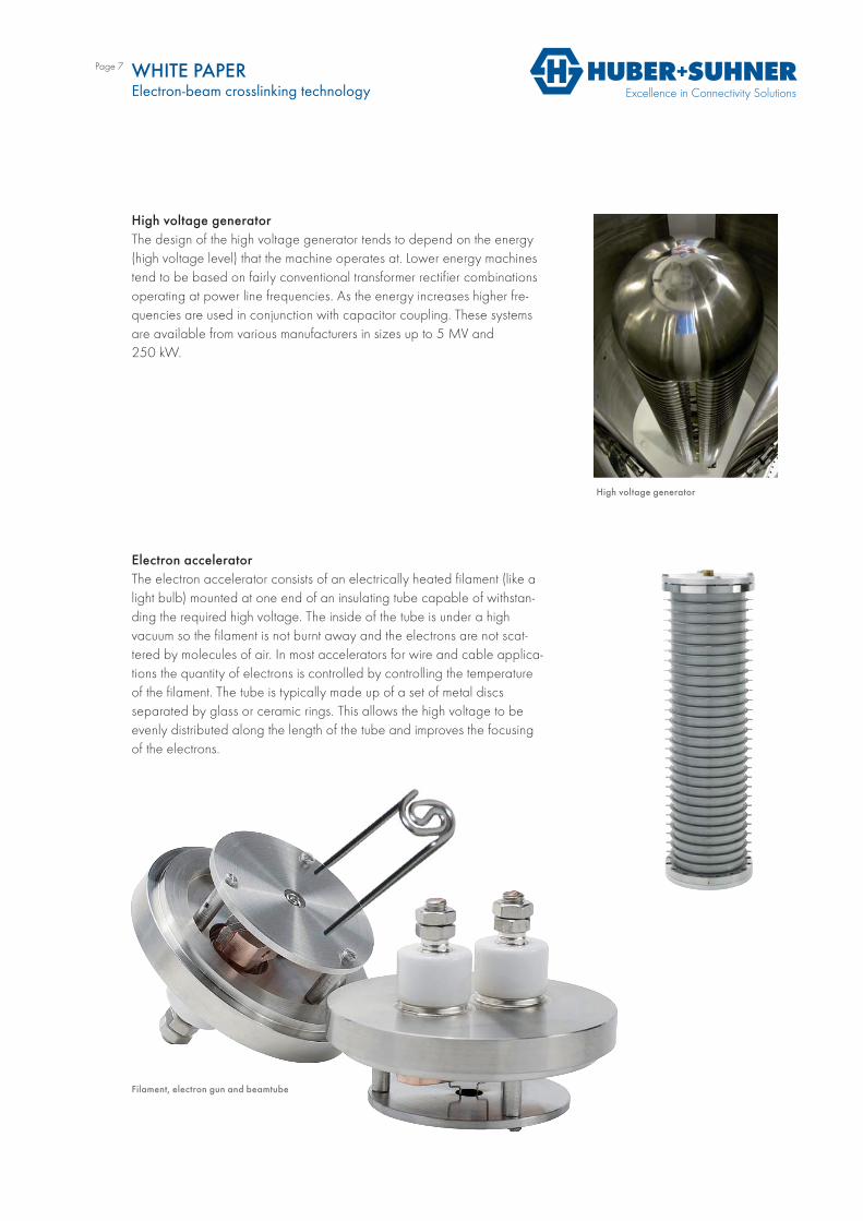
High voltage generator
Page 7
High voltage generatorThe design of the high voltage generator tends to depend on the energy (high voltage level) that the machine operates at. Lower energy machines tend to be based on fairly conventional transformer rectifier combinations operating at power line frequencies. As the energy increases higher fre-quencies are used in conjunction with capacitor coupling. These systems are available from various manufacturers in sizes up to 5 MV and250 kW.
Electron acceleratorThe electron accelerator consists of an electrically heated filament (like a light bulb) mounted at one end of an insulating tube capable of withstan-ding the required high voltage. The inside of the tube is under a highvacuum so the filament is not burnt away and the electrons are not scat-tered by molecules of air. In most accelerators for wire and cable applica-tions the quantity of electrons is controlled by controlling the temperature of the filament. The tube is typically made up of a set of metal discsseparated by glass or ceramic rings. This allows the high voltage to be evenly distributed along the length of the tube and improves the focusing of the electrons.
WHITE PAPERElectron-beam crosslinking technology
Filament, electron gun and beamtube
Page 8
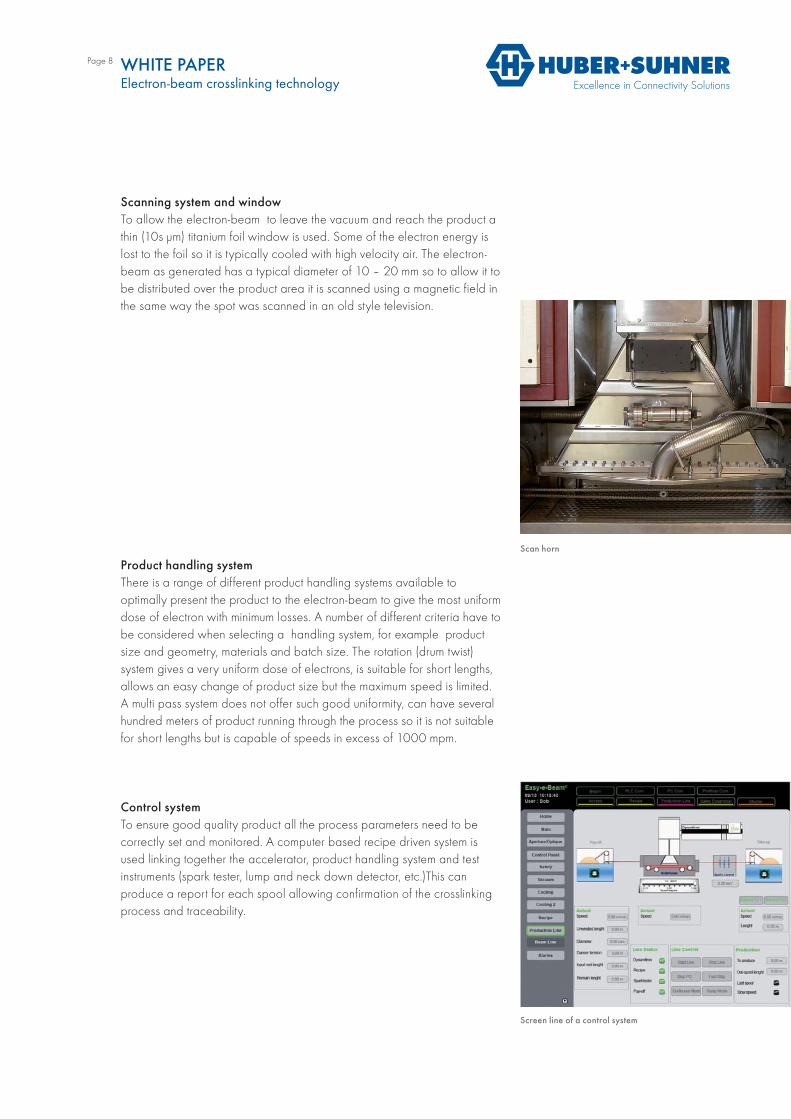
Scanning system and windowTo allow the electron-beam to leave the vacuum and reach the product a thin (10s μm) titanium foil window is used. Some of the electron energy is lost to the foil so it is typically cooled with high velocity air. The electron-beam as generated has a typical diameter of 10 – 20 mm so to allow it to be distributed over the product area it is scanned using a magnetic field in the same way the spot was scanned in an old style television.
Product handling systemThere is a range of different product handling systems available tooptimally present the product to the electron-beam to give the most uniform dose of electron with minimum losses. A number of different criteria have to be considered when selecting a handling system, for example product size and geometry, materials and batch size. The rotation (drum twist)system gives a very uniform dose of electrons, is suitable for short lengths, allows an easy change of product size but the maximum speed is limited. A multi pass system does not offer such good uniformity, can have several hundred meters of product running through the process so it is not suitable for short lengths but is capable of speeds in excess of 1000 mpm.
Control systemTo ensure good quality product all the process parameters need to becorrectly set and monitored. A computer based recipe driven system is used linking together the accelerator, product handling system and test instruments (spark tester, lump and neck down detector, etc.)This canproduce a report for each spool allowing confirmation of the crosslinking process and traceability.
WHITE PAPERElectron-beam crosslinking technology
Screen line of a control system
Scan horn
Page 9
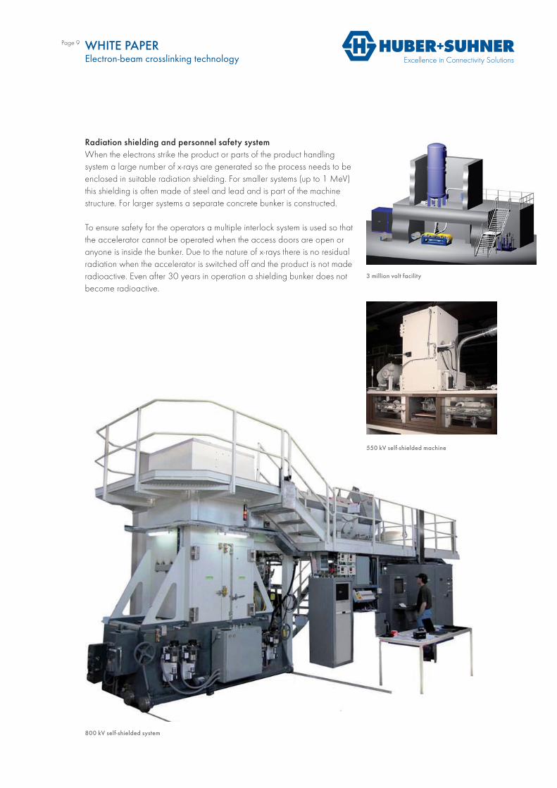
Radiation shielding and personnel safety systemWhen the electrons strike the product or parts of the product handlingsystem a large number of x-rays are generated so the process needs to be enclosed in suitable radiation shielding. For smaller systems (up to 1 MeV) this shielding is often made of steel and lead and is part of the machine structure. For larger systems a separate concrete bunker is constructed.
To ensure safety for the operators a multiple interlock system is used so that the accelerator cannot be operated when the access doors are open or anyone is inside the bunker. Due to the nature of x-rays there is no residual radiation when the accelerator is switched off and the product is not made radioactive. Even after 30 years in operation a shielding bunker does not become radioactive.
WHITE PAPERElectron-beam crosslinking technology
3 million volt facility
550 kV self-shielded machine
800 kV self-shielded system
Page 10
Process optimisation by three dimensionalcomputer simulation
Today process parameters are in general generated using empirical data and analytical formulas based on very general one-dimensional (1D) depth dose profiles. These tools are not tailored to specific accelerator facilities and radiation processes, and neither consider the full three-dimen-sional (3D) problem nor time-dependency. For these reasons their validity must be checked for each new product and the models as well as themachine parameters must be adjusted empirically to match the results with the experimental data.
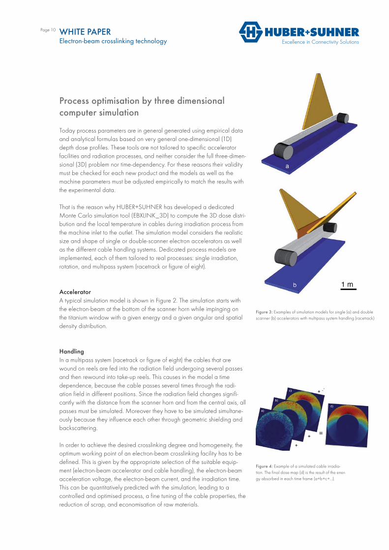
That is the reason why HUBER+SUHNER has developed a dedicated Monte Carlo simulation tool (EBXLINK_3D) to compute the 3D dose distri-bution and the local temperature in cables during irradiation process from the machine inlet to the outlet. The simulation model considers the realistic size and shape of single or double-scanner electron accelerators as well as the different cable handling systems. Dedicated process models are implemented, each of them tailored to real processes: single irradiation, rotation, and multipass system (racetrack or figure of eight).
AcceleratorA typical simulation model is shown in Figure 2. The simulation starts with the electron-beam at the bottom of the scanner horn while impinging on the titanium window with a given energy and a given angular and spatial density distribution.
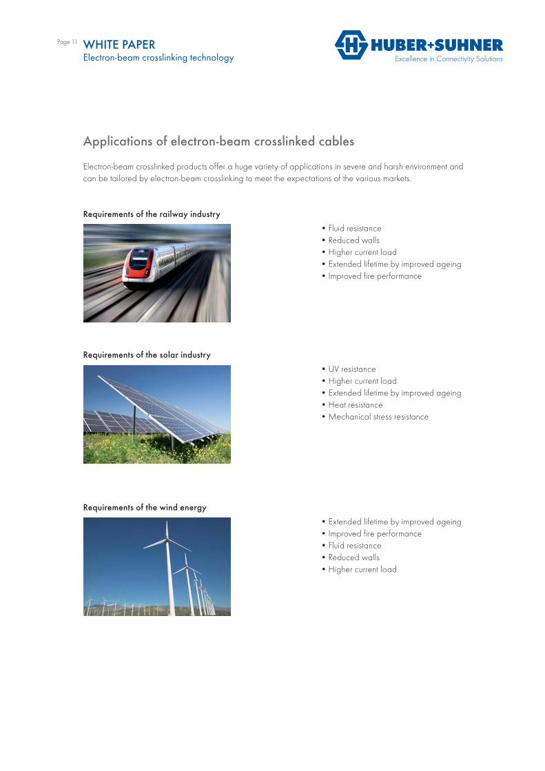
HandlingIn a multipass system (racetrack or figure of eight) the cables that are wound on reels are fed into the radiation field undergoing several passes and then rewound into take-up reels. This causes in the model a timedependence, because the cable passes several times through the radi-ation field in different positions. Since the radiation field changes signifi-cantly with the distance from the scanner horn and from the central axis, all passes must be simulated. Moreover they have to be simulated simultane-ously because they influence each other through geometric shielding and backscattering.
In order to achieve the desired crosslinking degree and homogeneity, the optimum working point of an electron-beam crosslinking facility has to be defined. This is given by the appropriate selection of the suitable equip-ment (electron-beam accelerator and cable handling), the electron-beam acceleration voltage, the electron-beam current, and the irradiation time. This can be quantitatively predicted with the simulation, leading to acontrolled and optimised process, a fine tuning of the cable properties, the reduction of scrap, and economisation of raw materials.
Figure 3: Examples of simulation models for single (a) and double scanner (b) accelerators with multipass system handling (racetrack)
Figure 4: Example of a simulated cable irradia-tion. The final dose map (d) is the result of the ener-gy absorbed in each time frame (a+b+c+…).
WHITE PAPERElectron-beam crosslinking technology
Page 11 WHITE PAPERElectron-beam crosslinking technology
Applications of electron-beam crosslinked cables
Electron-beam crosslinked products offer a huge variety of applications in severe and harsh environment and can be tailored by electron-beam crosslinking to meet the expectations of the various markets.
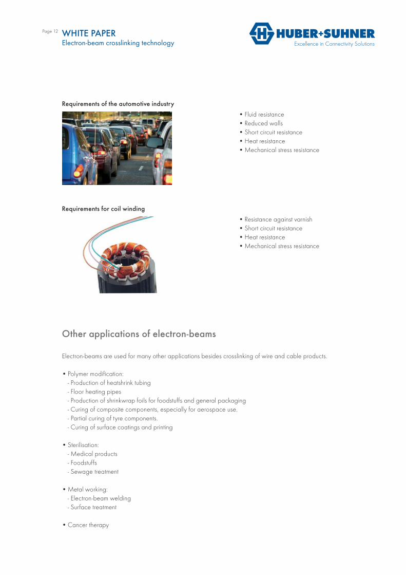
Requirements of the railway industry
• Fluid resistance• Reduced walls• Higher current load• Extended lifetime by improved ageing• Improved fire performance
Requirements of the solar industry
• UV resistance• Higher current load• Extended lifetime by improved ageing• Heat resistance• Mechanical stress resistance
Requirements of the wind energy
• Extended lifetime by improved ageing• Improved fire performance• Fluid resistance• Reduced walls• Higher current load
Page 12 WHITE PAPERElectron-beam crosslinking technology
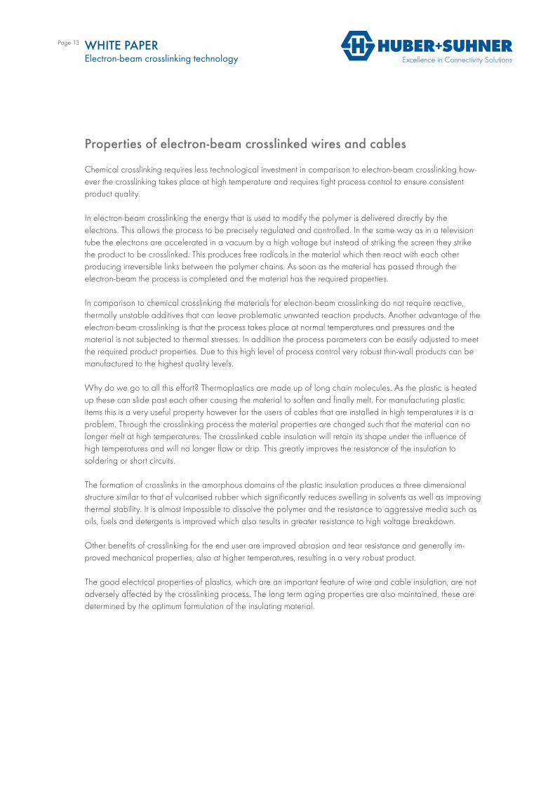
Requirements of the automotive industry
• Fluid resistance• Reduced walls• Short circuit resistance• Heat resistance• Mechanical stress resistance
Requirements for coil winding
• Resistance against varnish• Short circuit resistance• Heat resistance• Mechanical stress resistance
Other applications of electron-beams
Electron-beams are used for many other applications besides crosslinking of wire and cable products.
• Polymer modification: - Production of heatshrink tubing- Floor heating pipes- Production of shrinkwrap foils for foodstuffs and general packaging- Curing of composite components, especially for aerospace use.- Partial curing of tyre components.- Curing of surface coatings and printing
• Sterilisation:- Medical products- Foodstuffs- Sewage treatment
• Metal working:- Electron-beam welding- Surface treatment
• Cancer therapy
Page 13 WHITE PAPERElectron-beam crosslinking technology
Properties of electron-beam crosslinked wires and cables
Chemical crosslinking requires less technological investment in comparison to electron-beam crosslinking how-ever the crosslinking takes place at high temperature and requires tight process control to ensure consistentproduct quality.
In electron-beam crosslinking the energy that is used to modify the polymer is delivered directly by theelectrons. This allows the process to be precisely regulated and controlled. In the same way as in a television tube the electrons are accelerated in a vacuum by a high voltage but instead of striking the screen they strike the product to be crosslinked. This produces free radicals in the material which then react with each otherproducing irreversible links between the polymer chains. As soon as the material has passed through theelectron-beam the process is completed and the material has the required properties.
In comparison to chemical crosslinking the materials for electron-beam crosslinking do not require reactive,thermally unstable additives that can leave problematic unwanted reaction products. Another advantage of the electron-beam crosslinking is that the process takes place at normal temperatures and pressures and thematerial is not subjected to thermal stresses. In addition the process parameters can be easily adjusted to meet the required product properties. Due to this high level of process control very robust thin-wall products can be manufactured to the highest quality levels.
Why do we go to all this effort? Thermoplastics are made up of long chain molecules. As the plastic is heated up these can slide past each other causing the material to soften and finally melt. For manufacturing plastic items this is a very useful property however for the users of cables that are installed in high temperatures it is a problem. Through the crosslinking process the material properties are changed such that the material can no longer melt at high temperatures. The crosslinked cable insulation will retain its shape under the influence of high temperatures and will no longer flow or drip. This greatly improves the resistance of the insulation tosoldering or short circuits.
The formation of crosslinks in the amorphous domains of the plastic insulation produces a three dimensional structure similar to that of vulcanised rubber which significantly reduces swelling in solvents as well as improving thermal stability. It is almost impossible to dissolve the polymer and the resistance to aggressive media such as oils, fuels and detergents is improved which also results in greater resistance to high voltage breakdown.
Other benefits of crosslinking for the end user are improved abrasion and tear resistance and generally im-proved mechanical properties, also at higher temperatures, resulting in a very robust product.
The good electrical properties of plastics, which are an important feature of wire and cable insulation, are not adversely affected by the crosslinking process. The long term aging properties are also maintained, these are determined by the optimum formulation of the insulating material.
Page 14
Closing
Electron-beam crosslinking ensures that cables in harsh environments keep long-term functionality. Cables in engine compartments and in trains or connections for solar modules need to work safely and reliably evenunder adverse circumstances. Cables used in these applications need to be extremely resistant against very low and high temperatures, soldering and short circuits as well as aggressive media such as oils, fuels anddetergents. Further they need to be abrasion resistant and provide excellent mechanical properties. Electron-beam crosslinking assures these characteristics for the insulation and sheath materials of electrical wires and cables.
For more than 30 years HUBER+SUHNER has designed and manufactured wires and cables based onspecially developed compounds and the technology of electron-beam crosslinking. The compounds areproduced to recipes developed by HUBER+SUHNER. To maintain its position at the forefront of materialtechnology a state of the art automated compounding facility was built in 2011 in Switzerland. It is unique in the wire and cable industry. HUBER+SUHNER has a range of electron-beam crosslinking facilities with different energy levels and product handling systems, including inline with extrusion, to enable the optimal processing of the wide product range.
Over the last years HUBER+SUHNER has further optimised the process of electron-beam crosslinking forpower and signaling cables and now extends this to fiber optic and high frequency cables using the well-known RADOX® insulation and sheathing materials. The brand RADOX® stands for specially developedcompounds and for its robust electron-beam crosslinked insulation material. For decades the RADOX® cables have been used in many different fields and are known for their robustness, reliability and their long life.
Authors
Roger Bryant, Dr. René Köppel, Heinz Oesch, Dr. Stephan Ott, Dr. Maria Stangoni
Pictures
www.iba-cables.comwww.wasik.com
WHITE PAPERElectron-beam crosslinking technology

HUBER+SUHNER AG Low Frequency Division Tumbelenstrasse 208330 Pfäffikon ZHSwitzerland Phone +41 44 952 2211 Fax +41 44 952 2670 hubersuhner.com
HUBER+SUHNER is certified according to ISO 9001, ISO 14001, ISO/TS 16949 and IRIS.
23
26
/JS/
09
.201
2
WaiverFact and figures herein are for information only and do not represent any warranty of any kind.