Embed Size (px)
Citation preview
White Paper
6LoWPAN Fundamentals Introduction into the “Internet of Things”
Author
Enrico Lehmann
dresden elektronik ingenieurtechnik gmbh
July 2012

White paper
July 2012
6LoWPAN fundamentals
www.dresden-elektronik.de
Page 2 of 18
Abstract
So far wireless networks complying with the IEEE 802.15.4 standard are based on proprietary proto-
cols. But this does neither enable options of simple expandability nor can these networks interoperate
with other ones. In contrast, there is the internet established on free specifications the reason of which
its success is based. Together with the just starting introduction of the new internet protocol version 6
there is the option now to assign a worldwide unique address to almost any device. The idea came up
to connect sensor networks with the IPv6 world. For this reason the IPv6 over Low power Wireless
Personal Area Networks (6LoWPAN) task group of the Internet Engineering Task Force (IETF) has
been established to deal with this topic.
The task group has created the fundamentals to connect wireless networks to the internet. In this
white paper the 6LoWPAN technology shall be explained more detailed; the functional principle and
problems are discussed. Concluding some fields of application are described and the future use of
other protocols is explained.

White paper
July 2012
6LoWPAN fundamentals
www.dresden-elektronik.de
Page 3 of 18
Introduction
Figure 1 shows an exemplary company’s intranet with a built-on 6LoWPAN radio network. The uplink
to the internet is executed via the board router, called edge router, too. To this router more network
components can be connected. In the shown case these are the company server, an individual per-
sonal computer, another subnet which is managed by the router SR1, and the 6LoWPAN network
which has to be explained in detail. On the one hand the 6LoWPAN router ensures the data exchange
between the radio nodes and the intranet, on the other hand it generates and manages the radio sub-
net.
Figure 1: IPv6 network with 6LoWPAN radio network
To better understand the 6LoWPAN functional principle the following section introduces into the fun-
damentals of IPv6. It explains the address structure and presents some important address spaces and
categories. To illustrate the differences to the IPv4, the IPv6 header and the new procedure of the so
called auto configuration are described. The subsequent section discusses the main topic: 6LoWPAN.
The procedure is introduced and the protocol explained in detail.

White paper
July 2012
6LoWPAN fundamentals
www.dresden-elektronik.de
Page 4 of 18
Glossary
The glossary gives an overview of the terms and definitions used in this white paper.
Term Description
802.15.4 IEEE 802.15.4-standard, applicable to low-rate wireless Personal Area Network (WPAN)
6LoWPAN IPv6 over Low power Wireless Personal Area Networks
CIDR Classless Inter-Domain Routing
DAD Duplicate Address Detection
EUI Acronym for Extended Unique Identifier (forming MAC addresses)
Hop Stopover of a route as well as the way from one network node to the next
HTTP Hypertext Transfer Protocol
IDD Interface identifier
IETF Internet Engineering Task Force
IPv6 Internet protocol version 6, version of the Internet Protocol (IP) intended to suc-ceed IPv4 which is the protocol currently used to direct almost all internet traffic.
MAC Medium Access Control ... layer, address etc.
MTU Maximum Transmission Unit
NDP Neighbor Discovery Protocol
OSI Open Systems Interconnection (OSI) model, a prescription of characterizing and standardizing the functions of a communications system in terms of abstraction layers
PHY OSI model layer 1: The physical layer defines electrical and physical specifications for devices. It defines the relationship between a device and a transmission medi-um including the layout of all hardware components.
PSDU PHY service data unit
RFC List of Request For Comments memoranda (available from the IETF website)
RPL Routing Protocol for low power and Lossy networks
ROLL Routing Over Low power and Lossy networks
SOAP Simple Object Access Protocol, a protocol specification for exchanging structured information in the implementation of web services in computer networks
TCP Transmission Control Protocol
UDP User Datagram Protocol
WPAN Wireless personal area network

White paper
July 2012
6LoWPAN fundamentals
www.dresden-elektronik.de
Page 5 of 18
Internet protocol version 6 (IPv6)
Today’s internet is based on internet protocol version 4 (IPv4). Developed in the nineteen-eighties it
provides more than 4 billion addresses. Caused by the growth of web-enabled devices scientists as-
sumed that at the end of 2011 no more IPv4 addresses would be available [1]. At this point the 1995
standardized Internet protocol (IP) version 6 launches. It covers an address space of 2128
addresses,
that would be 6.7 ·1023
addresses per square meter surface of the earth. Therewith the new require-
ments can be accommodated for decades.
IPv6 addresses
The specification of an IPv6 address is carried out similar as with an IPv4 address; according to the
Classless Inter-Domain Routing (CIDR) procedure, which sub-divides the address into a network and
a host part.
IPv6 address/prefix length
2001:0CFF:0:CD30::/60
But as apparent, the notation differs at the IPv6 compared to IPv4. Because of the huge address
space the IPv6 addresses are outlined in hexadecimal notation and separated into blocks consisting of
16 bit each, separated by colon, and combined. Foremost zeros can be removed; blocks of succes-
sive zeros can be replaced by ‘::’ one-time. The following example illustrates it again.
AA12:BBFD:0000:0000:0000:0000:CAFE:0011
AA12:BBFD::CAFE:11
An IPv6 address is never linked to a system (e.g. a PC), but to its interface. On the other hand an in-
terface can have multiple IPv6 addresses. The addresses are categorized and sub-divided into
unicast, anycast and multicast. Table 1 explains the different categories more detailed and Table 2
lists some important IPv6 addresses. Link local unicast addresses denote link-local addresses, which
are only accessible in the own subnet (the router does not forward the packets). They consist of the
prefix (see Table 2) and the so called 64 bit large interface identifier (IDD). Often the link-layer ad-
dress (also called MAC address) of the interface is used for it. Global unicast addresses are worldwide
unique and routable IPv6 addresses. In general they consist of a 64 bit prefix and the interface 64 bit
identifier, too.

White paper
July 2012
6LoWPAN fundamentals
www.dresden-elektronik.de
Page 6 of 18
Category Setup / Description
Unicast
A packet with unicast destination address is only sent to the interface with this address.
Anycast
Anycast addresses are generated from unicast addresses, so they are syntactically identical. The anycast address is valid for multiple interfaces, but the packet is only sent to one of these interfaces (always to the nearest one, depending on the routing protocol).
Multicast
Packets with multicast destination address are sent to all interfaces.
Table 1: IPv6 address categories
The elective range of multicast packets can be affected via the address variables flags und scope (see
Table 1; more information you can find in RFC 4291. Multicast packets can only be sent or received
inside of a subnet, or worldwide, with the appropriate settings.
Address type Compressed notation Notation in detail Prefix binary
Undefined ::/128 0:0:0:0:0:0:0:0/128 00…00 (128 Bits)
Loopback ::1/128 0:0:0:0:0:0:0:1/128 00…01 (128 Bits)
Multicast FF00::/8 FF00::/8 11111111
Link Local Unicast FE80::/10 FE80::/10 1111111010
Global Unicast All other addresses
Table 2: Important IPv6 addresses

White paper
July 2012
6LoWPAN fundamentals
www.dresden-elektronik.de
Page 7 of 18
IPv6 header
To get a better understanding of the 6LoWPAN procedure the IPv6 header shall be explained more
detailed now.
Figure 2: IPv6 header
In Figure 2 the IPv6 header is shown; it consists of the fields that are briefly explained below: The first
field specifies the version of the protocol, in this case version 6. The following fields Traffic Class and
Flow Label affect the treatment of IPv6 packets in routers (e.g. priority). Payload Length indicates the
length of the subsequent payload data. The subsequent protocol (e.g. TCP or UDP) is identified via
Next Header. The value Hop Limit defines the maximal number of hops (way from one network node
to the next) an IPv6 packet can pass. In Source and Destination Address respectively the 128 bit long
source and destination address are included.
Auto configuration
The IPv6 auto configuration procedure is an essential modification compared to IPv4. It allows a node
to autonomously generate a complete IPv6 address without the requirement of manual intervention or
the need of configuration servers. To get an address, a host communicates via Neighbor Discovery
Protocol (NDP) with the participants of the own subnet. The procedure works as shown in the scheme
of Figure 3. The following four message types are applied:
Router Solicitation
Router Advertisement
Neighbor Solicitation
Neighbor Advertisement
The router solicitation messages include, among others options, the valid prefix for the subnet. The
messages are periodically sent out by all routers. If a host wants to participate in the network it as-
signs itself a link-local unicast address (FE80::<64 Bit IID>). Then it sends this address via the
neighbor solicitation message to all other participants in the subnet to check if this address is not yet
occupied. If the host doesn’t get a neighbor advertisement (NA) message within a defined timeframe it

White paper
July 2012
6LoWPAN fundamentals
www.dresden-elektronik.de
Page 8 of 18
can assume that the address is unique. This procedure is also called Duplicate Address Detection
(DAD). To get the correct network prefix now, the host sends a router solicitation message to the rout-
er to get the correct network prefix with the router advertisement message.
Using these four messages a host is enabled to assign itself a worldwide valid IPv6 address.
Figure 3: Data flow of an auto configuration
6LoWPAN
To transmit IPv6 packets inside of 802.15.4 networks two high hurdles have to be overcome. The first
is the maximal available payload size of 127 bytes. From this value 25 bytes for the MAC header itself
and another 40 bytes for the IPv6 header have to be subtracted. Thus 62 bytes remain for payload. If
encryption and/or other application protocols (e.g. TCP, UDP, ...) are to be added, the available
memory space decreases rapidly. Figure 4 illustrates this complex of problems. To counteract this,
technologies for header compression have been developed [RFC 4919, RFC 4944].

White paper
July 2012
6LoWPAN fundamentals
www.dresden-elektronik.de
Page 9 of 18
Figure 4: Ratio of header data and payload
The second hurdle is the IPv6’s Maximum Transmission Unit (MTU) of 1280 bytes. It is the minimum
value the MAC layer has to provide to be able to send IPv6 packets without fragmentation. Because
this is obviously not possible a fragmentation and defragmentation layer has to be implemented; it fa-
cilitates to subdivide IPv6 packets on 802.15.4 frames and reassemble them afterwards.
The different tasks such as header compression, fragmentation, routing and auto configuration are
abstracted to the term “adaptation layer” and define the term 6LoWPAN.
Routing under 6LoWPAN
By means of routing packets are transmitted from a source node to a destination node, sometimes via
multiple hops. Depending on the layer where the routing is applied the protocols are classified into two
different categories: Mesh-under and route-over. The first uses the MAC address and 16 Bit short ad-
dress (layer 2 address) respectively to forward packets, the latter uses the IP addressing (layer 3) for
it. Figure 5 illustrates the scheme of the two procedures.
Figure 5: Difference Mesh-Under vs. Router-Over Routing
Since routing inside of a mesh-under network happens transparently, mesh-under networks are con-
sidered to be the only IP subnet, too. The only IP router inside of such a network is the boarder router.
Thus for the complete 6LoWPAN radio network a broadcast domain is established that ensures the
compatibility to some IPv6 protocols; for example the above explained procedure to ensure that no
double addresses exist. These messages have to be sent to all participants of the network, this is al-
ways ensured by the routing scheme. Thus in turn, a high network load is generated because these
packets always have to be sent to all participants. Mesh-under is therefore suitable for local limited
and small networks. Larger networks can be implemented by this means, too, if multicast packets are
avoided and replaced by unicast packets if possible.

White paper
July 2012
6LoWPAN fundamentals
www.dresden-elektronik.de
Page 10 of 18
In route-over networks however routing is run in the IP layer; thus each hop represents an IP router
[2], [3]. But it also means that each hop in the network has to come with the accordant features of an
IP router such as neighbor discovery. This in turn allows the application of IP functionalities e.g. IPv6
routing, management services as well as configuration. The usage of IP routing is also the basic prin-
ciple to be independent from lower level layers; it simplifies the integration of more powerful networks.
Furthermore messages are not sent via broadcast, but only to the nodes within the radio range. This
however limits protocols (neighbor discovery) that always send multicast packets to all participants. In
this case the messages have to be transferred across router boarders.
One protocol for route-over networks, just running through a standardization approval stage, is the
Routing Protocol for low power and Lossy networks (RPL). More information about that you can find
on the page of the task group Routing Over Low power and Lossy networks1 (ROLL) of the IETF. On
the basis of this statement a clear trend is already visible indicating the routing procedure to be intro-
duced into the products. Compared to mesh-under, route-over features the advantage that most of the
protocols can be applied without any changes; problems during routing via layer 2 can be avoided. For
this can cause malfunctions, if different networks are connected to each other and different routing
procedures on layer 2 are applied; and this is no longer visible in layer 3.
Fragmentation
Fragmentation provides a basis to subdivide a large packet into several smaller ones. For this purpose
additional data are generated in each packet to be able to reassemble the packets in the correct se-
quence at the end. This step is called defragmentation. When reassembling, the additionally generat-
ed data are removed and the packets are combined again to a complete total package.
The procedure is apparently necessary in case of the 6LoWPAN because one IPv6 packet can be up
to 1280 bytes long, but the maximal packet size in IEEE 802.15.4 is only127 bytes.
In case of fragmentation a different behavior in dependence of the applied routing has to be consid-
ered, too. In mesh-under networks for example the fragments are routed to the destination node, not
until here they are assembled. Route-over networks however transmit each fragment only to the next
hop. There all fragments are assembled and the complete packet is analyzed to determine the next
destination node. Thus in route-over networks each hop has to store all fragments and must therefore
have enough resources available. Using mesh-under this is not required, instead of that a lot of net-
work traffic is generated rapidly because all fragments are immediately passed; if any fragment gets
lost the complete packet has to be requested anew [4].
1 http://datatracker.ietf.org/wg/roll/ state: 2011-07-08

White paper
July 2012
6LoWPAN fundamentals
www.dresden-elektronik.de
Page 11 of 18
In general it should be tried to avoid fragmentation. On the one hand the administration effort to im-
plement the procedure is growing; then again, enough memory (minimum 1280 Bytes) always has to
be available to ensure a reliable procedure. Especially for resource-limited devices this is a bottleneck
in most cases. Often on closer consideration the substantial important data can be reduced to a mini-
mum, so all relevant data can fit in a packet. These measures are by far more efficient; they reduce
the network load and enable a longer life time of battery-powered devices.
Auto configuration
Auto configuration describes the autonomous generation of a complete IPv6 address. It consists of the
64 Bit prefix together with the following 64 bit interface identifier (IID); the latter is generated by the
node itself. If the interface of the device is based on a EUI-64 address, as intended in the IEEE
802.15.4 standard, the modified EUI-64 procedure can be used to generate the IID, see Figure 6. It is
also possible to use the 16 bit short address. A pseudo 48 bit address accordant to the following
scheme is provided:
16_Bit_PAN_ID : 16_Bit_Zeros : 16_Bit_Short_Address
The IID in turn is generated from this address with the Modified EUI-64 method. But in general it is not
recommended using the short address as IID; the short address is only valid as long as there is an
established connection to the PAN coordinator. If the PAN coordinator becomes inactive or the con-
nection is interrupted (rebooting is required) the node can get another short address; this in turn caus-
es an invalid IID to the outside.
Figure 6: Modified EUI-64 procedure

White paper
July 2012
6LoWPAN fundamentals
www.dresden-elektronik.de
Page 12 of 18
The auto configuration consists of multiple messages, in this case the messages of the Neighbor Dis-
covery Protocol (NDP). To apply them inside LoWPANs, some challenges have to be overcome be-
cause messages such as Router Advertisement, Router Solicitation und Neighbor Solicitation are ad-
dressed to multicast addresses. Thus in the mesh-under network which represents a single IP link all
nodes inside the network have to be provided with the message. This in turn floods the network and
impairs the bandwidth considerably. On the other hand there is the advantage that the NDP can be
adopted without changes, for all nodes inside the network are accessible (provided that all nodes are
active).
In the route-over network we find a different situation. Because each hop represents an IP router, the
multicast becomes a broadcast for all nodes in the radio range. This admittedly limits the network load
to this range, but that’s why it does not solve the complex of problems of the necessary Duplicate Ad-
dress Detection (DAD): the check for double addresses, for the DAD demands a transitive network
(node A can send a packet to node B; node B can send a packet to node C; then node A can send a
packet to node C, too). In a transitive network the uniqueness of an address can be ensured by the
accessibility of all nodes. For a route-over network is not a transitive one, the uniqueness of an ad-
dress cannot be ensured [2].
These and other problem cases of the neighbor discovery protocol related to LoWPANs are discussed
in the internet draft [5]. Solutions are proposed and the appropriate innovations and extensions are
discussed. It is intended to replace multicast addresses by adequate unicast addresses. This will be
implemented by the expended application of the border router. It knows the addresses of all nodes
inside the network; at the same time it represents the interface to the network outside of the LoWPAN.
So nodes do not send a multicast for duplicate address detection, but a unicast to the border router.
More information about the application of NDP you can find in [5]. Meanwhile the internet draft is
standing before its standardization to the RFC.
Header compression
Header compressions are usual practice; there are different procedures for the IP header. The tradi-
tional procedure is status-based and transmits only the differences to the previous header. It is used at
point-to-point connections for it establishes a status between two end points. But for dynamically
changing networks the procedure is inapplicable; that’s why new ways have been searched and de-
veloped in [6].
The procedure applies two different methods for the compression of the IPv6 header. Firstly it re-
moves redundant information which can be derived from other layers or the context. The field Version
in the IPv6 header for example always has the value ‘6’, it can be assumed that the value doesn’t
change inside a LoWPAN network anymore; therefore the field can be removed. Also the length field
as well as the address information can be gained from the MAC header (it is arranged in front of the
IP header and logical one layer below the IP layer). Secondly for some IPv6 fields known standard
values are set; thus they can be transmitted more compactly. For example Traffic Class and Flow La-

White paper
July 2012
6LoWPAN fundamentals
www.dresden-elektronik.de
Page 13 of 18
bel are always zero, and the Hop Limit is set to the values of 1, 64 or 255. Optionally the compression
of arbitrary IPv6 prefixes can be executed. Thereto each node comes with a table of prefixes and a
number linked with it. The number is limited to 4 bits; so the table can include a maximum of 16 en-
tries. If the prefix is known only the number will be transmitted, but not the 8 byte long prefix [3]. How-
ever, a method how the table is filled with prefixes is not part of the specification [6].
Figure 7 exemplary shows the procedure of the IPv6 header compression. If a communication inside
of a 6LoWPAN Network runs the der IPv6 Header can be compressed to two bytes. If the prefix table
is used and the prefixes for the active subnet and the external net are known, the IPv6 Header can be
compressed to 12 bytes (see b). If in turn, the prefixes are not known and have to be inserted, a com-
pression rate of 50% can still be reached. In the examples it was assumed that the interface identifier
(IID) can be derived from the address fields of the MAC header.
Figure 7: Header compression
At the end it shall be remarked that in the specification [6] a procedure for compression of the User
Datagram Protocol (UDP) header is described. Therewith it is possible to reduce the 8 byte UDP
header up to 1 byte.
White paper
July 2012
6LoWPAN fundamentals
www.dresden-elektronik.de
Page 14 of 18
Application of other protocols
So far only the procedure to transmit IPv6 packets efficiently via radio networks has been described.
Of interest however are bottom-up protocols such as UDP and the known Transmission Control Proto-
col (TCP), on which in turn the Hypertext Transfer Protocol (HTTP) is bottom-up. For only by using
these protocols the already in practice existing and used applications can be operated. For the wire-
less and thus modest UDP protocol methods have been developed that allow to heavily compress the
header. For the by far more popular, admittedly connection oriented, Transmission Control Protocol
(TCP) there is no known procedure to easily compress it up to now. First developments to this took
place in RFC1144; it made TCP usable for serial interfaces. Developments via RFC 2507 lead on to
the current internet draft [7]. The latter is especially construed to the requirements of radio networks.
Despite of these developments it has not found its way into actual implementations (except the Berke-
ley IP Implementation BLIP2).
Other internet protocols, as e.g. HTTP, have not been developed aimed to be compact, machine-
readable and extendable; thus their handling for embedded systems is sophisticated and requires a
high operating effort. Furthermore no appropriate compressing procedures are available for use on
embedded systems. Applications atop of HTTP, for example SOAP come along with other difficulties.
SOAP applications are called web services and are XML based. They are predominantly used for ma-
chine-to-machine (M2M) network communication. Via SOAP, functions to access specific features of a
machine can be implemented. XML as human-readable format with high memory requirements is ra-
ther improper for radio nodes with a small band width although there are compression procedures
(WBXML, BXML, EXI). However they are only confined usable for embedded systems.
If you do not confine to TCP, but consider the UDP protocol more in detail, it can be stated, that it
comes with a number of application protocols that should not be underestimated. Here protocols exist
for the transport of real-time data, the management of networks up to simple file transfer protocols.
Moreover there are ongoing efforts to utilize web services for 6LoWPAN networks via UDP. So there
are developments trying to apply SOAP-over-UDP3 and its alternative, Representational State Trans-
fer (REST), in the field of radio networks. The latter undergoes a growing importance during the last
years; it is an architecture model which makes it possible to describe web services. In the Constrained
RESTful Environments4 (CoRE) task group of the IETF specifications are worked out, by means of
which resource limited devices can be operated via web services. For that the Constrained Application
Protocol (CoAP) has been designed which exactly covers this assignment.
2 http://smote.cs.berkeley.edu:8000/tracenv/wiki/blip
3 http://docs.oasis-open.org/ws-dd/soapoverudp/1.1/os/wsdd-soapoverudp-1.1-spec-os.html
4 https://datatracker.ietf.org/wg/core/charter/
White paper
July 2012
6LoWPAN fundamentals
www.dresden-elektronik.de
Page 15 of 18
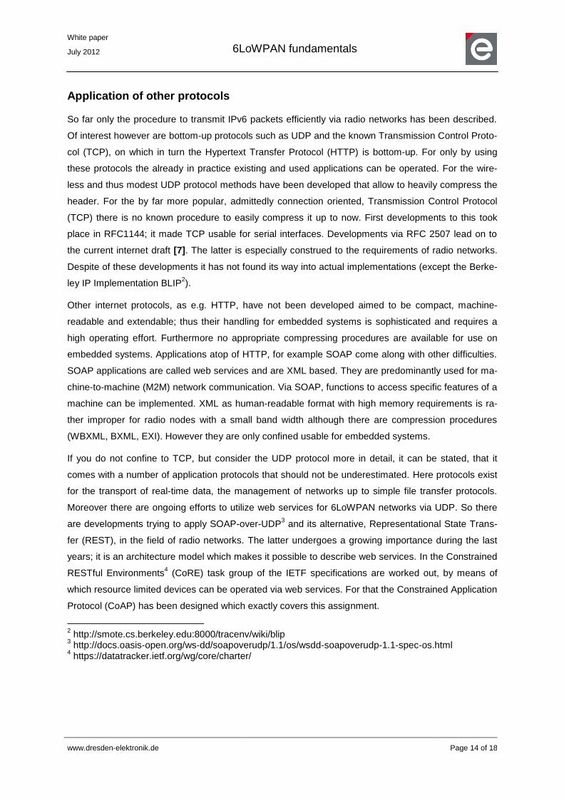
Fields of application
In the facility management this technology can serve to monitor temperatures and to control the air
conditioning. Light sensors can be installed to be used to control the artificial light inside of the building
automatically according to the naturally existent amount of light. This may result in high reduction of
costs; furthermore the central control via server is possible from the outside, contributing to comforta-
ble operation and high convenience.
Figure 8: Building automation [8]
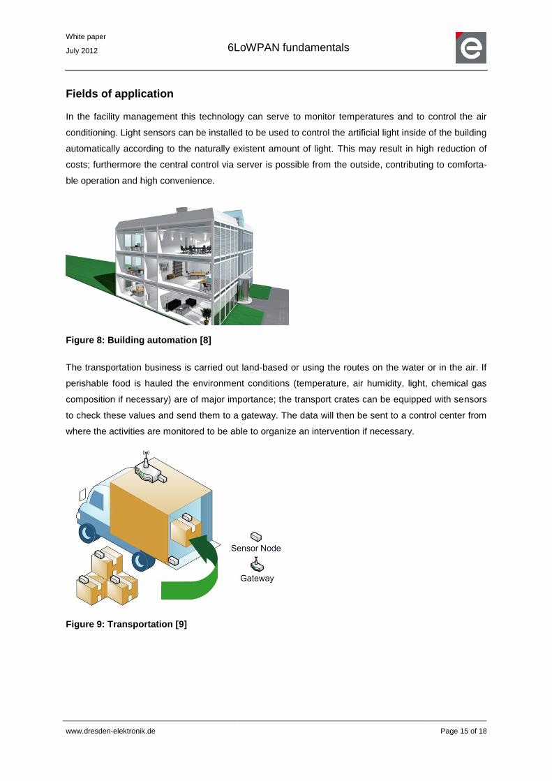
The transportation business is carried out land-based or using the routes on the water or in the air. If
perishable food is hauled the environment conditions (temperature, air humidity, light, chemical gas
composition if necessary) are of major importance; the transport crates can be equipped with sensors
to check these values and send them to a gateway. The data will then be sent to a control center from
where the activities are monitored to be able to organize an intervention if necessary.
Figure 9: Transportation [9]
White paper
July 2012
6LoWPAN fundamentals
www.dresden-elektronik.de
Page 16 of 18
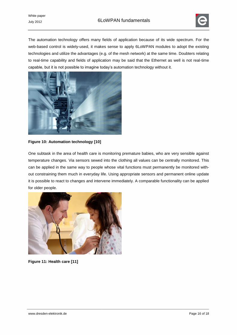
The automation technology offers many fields of application because of its wide spectrum. For the
web-based control is widely-used, it makes sense to apply 6LoWPAN modules to adopt the existing
technologies and utilize the advantages (e.g. of the mesh network) at the same time. Doubters relating
to real-time capability and fields of application may be said that the Ethernet as well is not real-time
capable, but it is not possible to imagine today’s automation technology without it.
Figure 10: Automation technology [10]
One subtask in the area of health care is monitoring premature babies, who are very sensible against
temperature changes. Via sensors sewed into the clothing all values can be centrally monitored. This
can be applied in the same way to people whose vital functions must permanently be monitored with-
out constraining them much in everyday life. Using appropriate sensors and permanent online update
it is possible to react to changes and intervene immediately. A comparable functionality can be applied
for older people.
Figure 11: Health care [11]

White paper
July 2012
6LoWPAN fundamentals
www.dresden-elektronik.de
Page 17 of 18
References
[1] http://en.wikipedia.org/wiki/IPv4_address_exhaustion
[2] Jonathan Hui/David Culler/Samita Chakrabarti: 6LoWPAN: Incorporating IEEE
802.15.4 into the IP architecture. White paper # 3. IPSO Alliance, 2009.
[3] Jonathan Hui/David Culler: IPv6 in Low-Power Wireless Networks. Proceedings
of the IEEE, 2010.
[4] Chowdhury, A.H./Ikram, M./Cha, H-S./Redwan, H./Shams,S.M.S/Kim, Ki-
H./Yoo, S-W.: Route-over vs. Mesh-under Routing in 6LoWPAN. International
Wireless Communications and Mobile Computing Conference 2009. Pages 1208-
1212.
[5] Shelby, Z./Chakrabarti, S./Nordmark, E.: Neighbor Discovery Optimization for
Low-power and Lossy Networks. Internet-Draft. 2010. URL:
http://tools.ietf.org/html/draft-ietf-6lowpan-nd-17, state: 2011-07-27.
[6] Hui, J./Thubert, P.: Compression Format for IPv6 Datagrams in6LoWPAN Net-
works. Internet-Draft. 2010. URL: http://tools.ietf.org/html/draft-ietf-6lowpan-hc-15,
state: 2011-07-27.
[7] Ayadi, A./Ros, D./Toutain, L.: TCP header compression for 6LoWPAN. Internet-
Draft. 2010. URL: http://datatracker.ietf.org/doc/draft-aayadi-6lowpan-tcphc/, state:
2011-07-27.
[8] http://www.wago.us/ , state: 2011-07-27.
[9] M. Becker/B.-L. Wenning/C. Görg/R. Jedermann/A. Timm-Giel: Logistic applica-
tions with Wireless Sensor Networks. HotEmNets 2010.
[10] http://www.mt-solutions.at, state: 2011-08-09.
[11] http://www.negotiationlawblog.com, state: 2011-07-27.
White paper
July 2012
6LoWPAN fundamentals
www.dresden-elektronik.de
Page 18 of 18
dresden elektronik ingenieurtechnik gmbh
Enno-Heidebroek-Straße 12
01237 Dresden
GERMANY
Phone +49 351 - 31850 0
Fax +49 351 - 31850 10
www.dresden-elektronik.de
E-mail [email protected]
Trademarks and acknowledgements
802.15.4™ is a trademark of the Institute of Electrical and Electronics Engineers (IEEE).
ZigBee® is a registered trademark of the ZigBee Alliance.
All trademarks are registered by their respective owners in certain countries only. Other brands and
their products are trademarks or registered trademarks of their respective holders and should be noted
as such.
Disclaimer
This note is provided as-is and is subject to change without notice. Except to the extent prohibited by
law, dresden elektronik ingenieurtechnik gmbh makes no express or implied warranty of any kind with
regard to this guide, and specifically disclaims the implied warranties and conditions of merchantability
and fitness for a particular purpose. dresden elektronik ingenieurtechnik gmbh shall not be liable for
any errors or incidental or consequential damage in connection with the furnishing, performance or
use of this guide.
No part of this publication may be reproduced, stored in a retrieval system, or transmitted in any form
or any means electronic or mechanical, including photocopying and recording, for any purpose other
than the purchaser’s personal use, without the written permission of dresden elektronik ingenieurtech-
nik gmbh.
Copyright © 2012 dresden elektronik ingenieurtechnik gmbh. All rights reserved.