Embed Size (px)
Citation preview
VIBRATION INSTITUTE 31st ANNUAL MEETING, SAN ANTONIO TEXAS, JUNE 19-22, 2007
WHIRL MOTION OF A SEAL TEST RIGWITH SQUEEZE-FILM DAMPERS
Edgar J. GunterRODYN Vibration Analysis, Inc.
Margaret P. ProctorNASA Glenn Research [email protected]
ABSTRACT
This paper presents the experimental behavior and dynamic analysis of a high speed test rig with rollingelement bearings mounted in squeeze film oil damper bearings. The test rotor is a double overhungconfiguration with rolling element ball bearings mounted in uncentered squeeze-film oil dampers. Thedamper design is similar to that employed with various high-speed aircraft HP gas turbines. Thedynamic performance of the test rig with the originally installed dampers with an effective damperlength of length 0.23-inch was unacceptable. The design speed of 40,000 RPM could not be safelyachieved as nonsynchronous whirling at the overhung seal test disk and high amplitude critical speedresponse at the drive spline section occurred at 32,000 RPM. In addition to the self excited stability andcritical speed problems, it was later seen from FFT data analysis, that a region of supersynchronous deadband whirling occurs between 10,000 to 15,000 RPM which can lead to bearing distress and wear. Thesystem was analyzed using both linear and nonlinear techniques. The extended length damper designresulting from the analysis eliminated the rotor subsynchronous whirling, high amplitude critical speed,and the dead band whirling region allowing the system to achieve a speed of 45,000 RPM. However,nonlinear analysis shows that damper lockup could occur with high rotor unbalance at 33,000 RPM,even with the extended squeeze-film dampers. The control of damper lockup will be addressed in afuture paper.
Keywords: Nonlinear whirl response, squeeze-film dampers, damper lockup, dead band whirl
INTRODUCTION
The NASA high temperature, high speed seal rig is designed to test seals over a range of conditionsincluding conditions expected in advanced gas turbine engines. The double overhung rotor has an 8.5inch seal test disk and is supported by rolling element bearings in squeeze film dampers. The maximumdesign speed of 43,140 rpm could not originally be achieved due to the occurrences of whirling at theseal test disk and high vibrations at the spline connection to the drive shaft. There were indications ofboth sub- and super-harmonic whirl motion at the seal test disk and high synchronous response at thebalance piston and drive spline. Experimental data indicated both a critical speed and whirling problemwith the rig. A nonlinear jump response region was observed between 10,000 to 15,000 RPM withsuperharmonic excitation. This region is referred to as dead band whirling and occurs even with a wellbalanced system.
The precise design of squeeze film dampers is complicated by the highly nonlinear nature of thedampers. Initial linear analysis of critical speeds and optimum damping for various assumed bearingstiffness values serve as a useful guide. The original damper was designed with the feature that thedamper length could be easily extended if needed.
Dyrobes Rotordynamics Softwarehttp://dyrobes.com
The critical speed analysis of the complete system including the drive train showed that the first twocritical speeds are associated with the seal test rotor. Nonlinear synchronous unbalance and timetransient whirl simulations were computed for the seal test rotor with the original dampers tosimulate the whirling and high synchronous response observed. With the original damper design, thenonlinear synchronous response showed that unbalance could cause damper lockup at 33,000 rpm.Alford cross-coupling forces were also included at the overhung seal test disk for the whirl analysis.Subsynchronous whirling at the seal test disk was observed in the nonlinear time transient analysis.With the extended damper length of 0.50 inch, the subsynchronous motion was eliminated and therotor unbalance response was acceptable to 45,000 rpm with moderate rotor unbalance. However,the nonlinear analysis shows that with high rotor unbalances, damper lockup could also be obtainedat 33,000 rpm, even with the extended squeeze-film dampers. Therefore, the test rotor must bereasonably balanced in order for the uncentered dampers to be effective.
1. SEAL TEST ROTOR
1.1 Description of Rotor System and Instrumentation
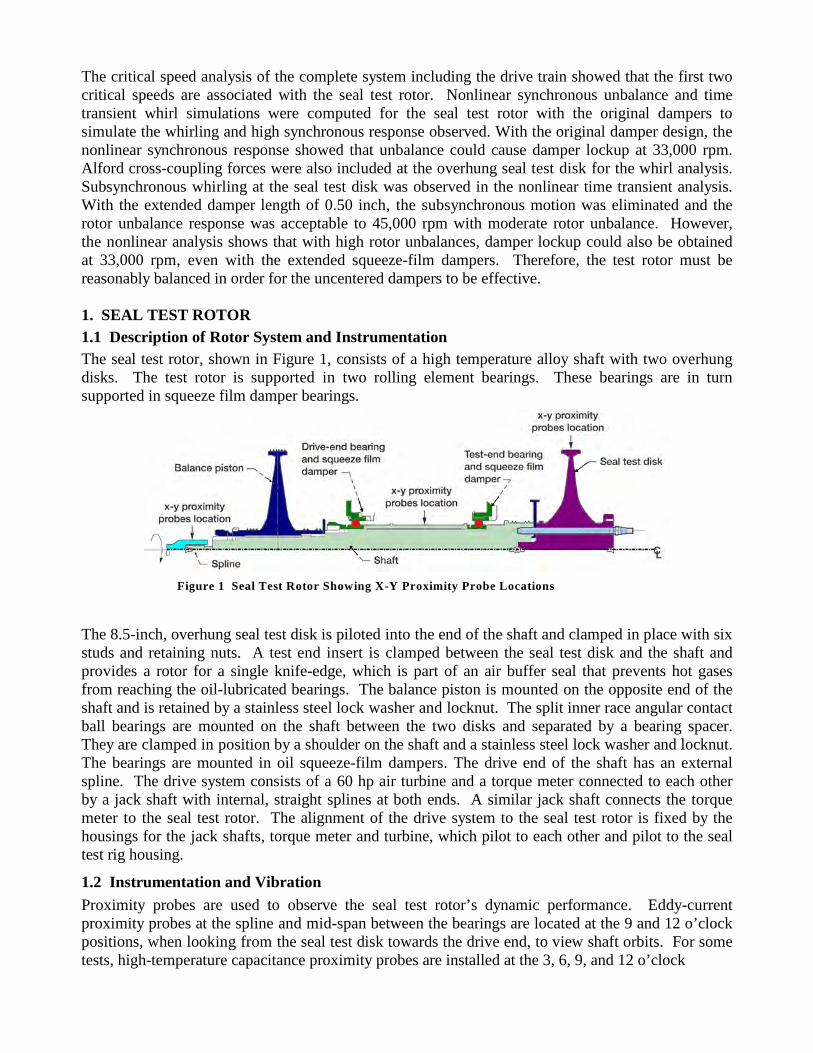
The seal test rotor, shown in Figure 1, consists of a high temperature alloy shaft with two overhungdisks. The test rotor is supported in two rolling element bearings. These bearings are in turnsupported in squeeze film damper bearings.
The 8.5-inch, overhung seal test disk is piloted into the end of the shaft and clamped in place with sixstuds and retaining nuts. A test end insert is clamped between the seal test disk and the shaft andprovides a rotor for a single knife-edge, which is part of an air buffer seal that prevents hot gasesfrom reaching the oil-lubricated bearings. The balance piston is mounted on the opposite end of theshaft and is retained by a stainless steel lock washer and locknut. The split inner race angular contactball bearings are mounted on the shaft between the two disks and separated by a bearing spacer.They are clamped in position by a shoulder on the shaft and a stainless steel lock washer and locknut.The bearings are mounted in oil squeeze-film dampers. The drive end of the shaft has an externalspline. The drive system consists of a 60 hp air turbine and a torque meter connected to each otherby a jack shaft with internal, straight splines at both ends. A similar jack shaft connects the torquemeter to the seal test rotor. The alignment of the drive system to the seal test rotor is fixed by thehousings for the jack shafts, torque meter and turbine, which pilot to each other and pilot to the sealtest rig housing.
1.2 Instrumentation and Vibration
Proximity probes are used to observe the seal test rotor’s dynamic performance. Eddy-currentproximity probes at the spline and mid-span between the bearings are located at the 9 and 12 o’clockpositions, when looking from the seal test disk towards the drive end, to view shaft orbits. For sometests, high-temperature capacitance proximity probes are installed at the 3, 6, 9, and 12 o’clock
Figure 1 Seal Test Rotor Showing X-Y Proximity Probe Locations
positions to view the seal test disk orbit and centrifugal growth. X-Y accelerometer pairs aremounted on the seal tester housing near the drive end bearings at the 9 and 12 o’clock positions andon the air turbine at the 12 and 3 o’clock positions. These measurements along with shaft speed arerecorded on a digital tape recorder. Orbits are monitored on oscilloscopes and a spectrum analyzer isused to look at the amplitude and frequency content of the signals.
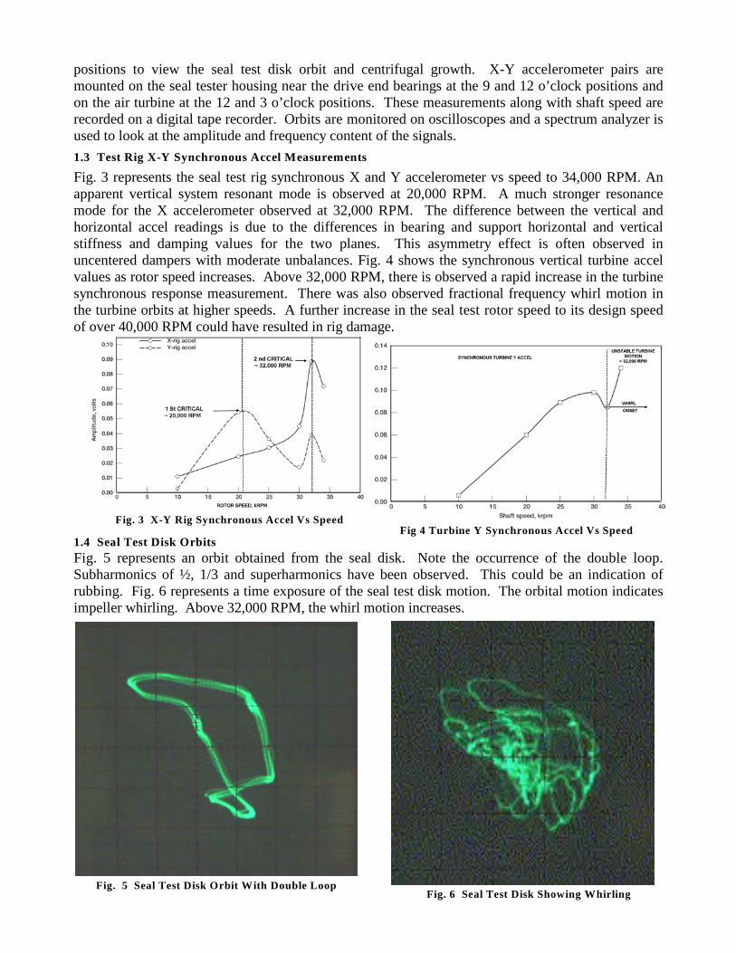
1.3 Test Rig X-Y Synchronous Accel Measurements
Fig. 3 represents the seal test rig synchronous X and Y accelerometer vs speed to 34,000 RPM. Anapparent vertical system resonant mode is observed at 20,000 RPM. A much stronger resonancemode for the X accelerometer observed at 32,000 RPM. The difference between the vertical andhorizontal accel readings is due to the differences in bearing and support horizontal and verticalstiffness and damping values for the two planes. This asymmetry effect is often observed inuncentered dampers with moderate unbalances. Fig. 4 shows the synchronous vertical turbine accelvalues as rotor speed increases. Above 32,000 RPM, there is observed a rapid increase in the turbinesynchronous response measurement. There was also observed fractional frequency whirl motion inthe turbine orbits at higher speeds. A further increase in the seal test rotor speed to its design speedof over 40,000 RPM could have resulted in rig damage.
1.4 Seal Test Disk Orbits
Fig. 5 represents an orbit obtained from the seal disk. Note the occurrence of the double loop.Subharmonics of ½, 1/3 and superharmonics have been observed. This could be an indication ofrubbing. Fig. 6 represents a time exposure of the seal test disk motion. The orbital motion indicatesimpeller whirling. Above 32,000 RPM, the whirl motion increases.
Fig 4 Turbine Y Synchronous Accel Vs SpeedFig. 3 X-Y Rig Synchronous Accel Vs Speed
Fig. 5 Seal Test Disk Orbit With Double Loop Fig. 6 Seal Test Disk Showing Whirling
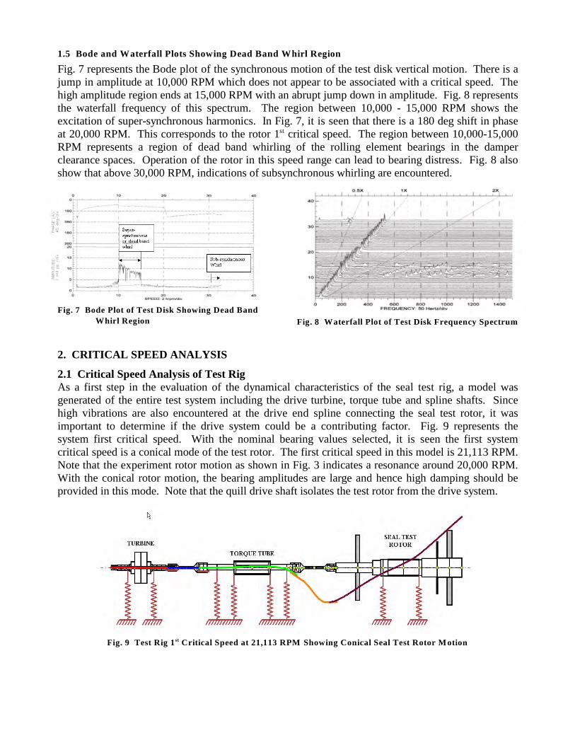
1.5 Bode and Waterfall Plots Showing Dead Band Whirl Region
Fig. 7 represents the Bode plot of the synchronous motion of the test disk vertical motion. There is ajump in amplitude at 10,000 RPM which does not appear to be associated with a critical speed. Thehigh amplitude region ends at 15,000 RPM with an abrupt jump down in amplitude. Fig. 8 representsthe waterfall frequency of this spectrum. The region between 10,000 - 15,000 RPM shows theexcitation of super-synchronous harmonics. In Fig. 7, it is seen that there is a 180 deg shift in phaseat 20,000 RPM. This corresponds to the rotor 1 critical speed. The region between 10,000-15,000st
RPM represents a region of dead band whirling of the rolling element bearings in the damperclearance spaces. Operation of the rotor in this speed range can lead to bearing distress. Fig. 8 alsoshow that above 30,000 RPM, indications of subsynchronous whirling are encountered.
2. CRITICAL SPEED ANALYSIS
2.1 Critical Speed Analysis of Test RigAs a first step in the evaluation of the dynamical characteristics of the seal test rig, a model wasgenerated of the entire test system including the drive turbine, torque tube and spline shafts. Sincehigh vibrations are also encountered at the drive end spline connecting the seal test rotor, it wasimportant to determine if the drive system could be a contributing factor. Fig. 9 represents thesystem first critical speed. With the nominal bearing values selected, it is seen the first systemcritical speed is a conical mode of the test rotor. The first critical speed in this model is 21,113 RPM.Note that the experiment rotor motion as shown in Fig. 3 indicates a resonance around 20,000 RPM.With the conical rotor motion, the bearing amplitudes are large and hence high damping should beprovided in this mode. Note that the quill drive shaft isolates the test rotor from the drive system.
Fig. 7 Bode Plot of Test Disk Showing Dead Band
Whirl Region Fig. 8 Waterfall Plot of Test Disk Frequency Spectrum
Fig. 9 Test Rig 1 Critical Speed at 21,113 RPM Showing Conical Seal Test Rotor Motionst
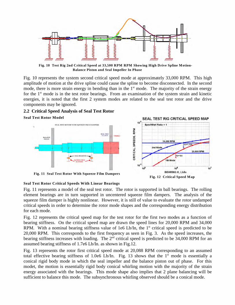
Fig. 10 represents the system second critical speed mode at approximately 33,000 RPM. This highamplitude of motion at the drive spline could cause the spline to become disconnected. In the secondmode, there is more strain energy in bending than in the 1 mode. The majority of the strain energyst
for the 1 mode is in the test rotor bearings. From an examination of the system strain and kineticst
energies, it is noted that the first 2 system modes are related to the seal test rotor and the drivecomponents may be ignored.
2.2 Critical Speed Analysis of Seal Test Rotor
Seal Test Rotor Model
Seal Test Rotor Critical Speeds With Linear Bearings
Fig. 11 represents a model of the seal test rotor. The rotor is supported in ball bearings. The rollingelement bearings are in turn supported in uncentered squeeze film dampers. The analysis of thesqueeze film damper is highly nonlinear. However, it is still of value to evaluate the rotor undampedcritical speeds in order to determine the rotor mode shapes and the corresponding energy distributionfor each mode.
Fig. 12 represents the critical speed map for the test rotor for the first two modes as a function ofbearing stiffness. On the critical speed map are drawn the speed lines for 20,000 RPM and 34,000RPM. With a nominal bearing stiffness value of 1e6 Lb/In, the 1 critical speed is predicted to best
20,000 RPM. This corresponds to the first frequency as seen in Fig. 3. As the speed increases, thebearing stiffness increases with loading. The 2 critical speed is predicted to be 34,000 RPM for annd
assumed bearing stiffness of 1.7e6 Lb/In. as shown in Fig.12.
Fig. 13 represents the rotor first critical speed mode at 20,088 RPM corresponding to an assumedtotal effective bearing stiffness of 1.0e6 Lb/In. Fig. 13 shows that the 1 mode is essentially ast
conical rigid body mode in which the seal impeller and the balance piston out of phase. For thismodet, the motion is essentially rigid body conical whirling motion with the majority of the strainenergy associated with the bearings. This mode shape also implies that 2 plane balancing will besufficient to balance this mode. The subsynchronous whirling observed should be a conical mode.
Fig. 10 Test Rig 2nd Critical Speed at 33,500 RPM RPM Showing High Drive Spline Motion-
Balance Piston and Seal Impeller In Phase
Fig. 12 Critical Speed MapFig. 11 Seal Test Rotor With Squeeze Film Dampers
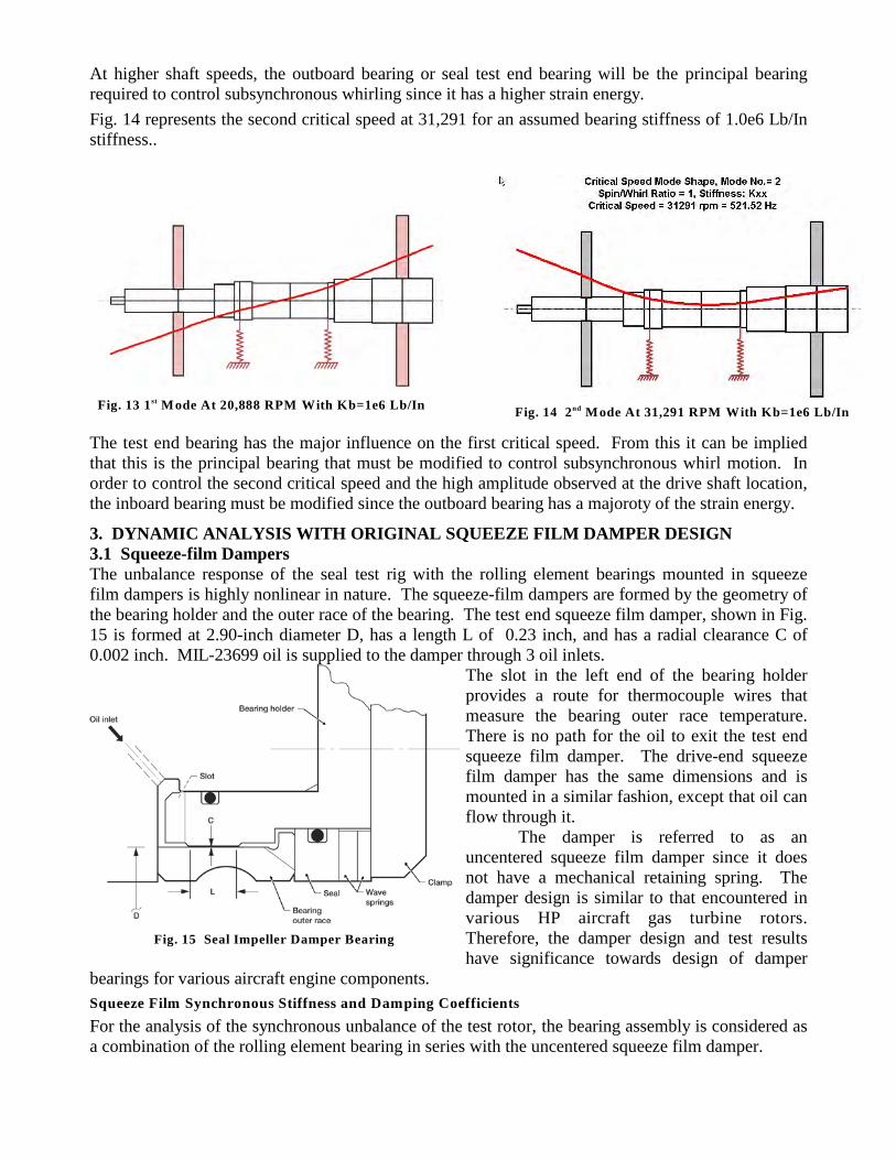
At higher shaft speeds, the outboard bearing or seal test end bearing will be the principal bearingrequired to control subsynchronous whirling since it has a higher strain energy.
Fig. 14 represents the second critical speed at 31,291 for an assumed bearing stiffness of 1.0e6 Lb/Instiffness..
The test end bearing has the major influence on the first critical speed. From this it can be impliedthat this is the principal bearing that must be modified to control subsynchronous whirl motion. Inorder to control the second critical speed and the high amplitude observed at the drive shaft location,the inboard bearing must be modified since the outboard bearing has a majoroty of the strain energy.
3. DYNAMIC ANALYSIS WITH ORIGINAL SQUEEZE FILM DAMPER DESIGN3.1 Squeeze-film Dampers The unbalance response of the seal test rig with the rolling element bearings mounted in squeezefilm dampers is highly nonlinear in nature. The squeeze-film dampers are formed by the geometry ofthe bearing holder and the outer race of the bearing. The test end squeeze film damper, shown in Fig.15 is formed at 2.90-inch diameter D, has a length L of 0.23 inch, and has a radial clearance C of0.002 inch. MIL-23699 oil is supplied to the damper through 3 oil inlets.
The slot in the left end of the bearing holderprovides a route for thermocouple wires thatmeasure the bearing outer race temperature.There is no path for the oil to exit the test endsqueeze film damper. The drive-end squeezefilm damper has the same dimensions and ismounted in a similar fashion, except that oil canflow through it.
The damper is referred to as anuncentered squeeze film damper since it doesnot have a mechanical retaining spring. Thedamper design is similar to that encountered invarious HP aircraft gas turbine rotors.Therefore, the damper design and test resultshave significance towards design of damper
bearings for various aircraft engine components.
Squeeze Film Synchronous Stiffness and Damping Coefficients
For the analysis of the synchronous unbalance of the test rotor, the bearing assembly is considered asa combination of the rolling element bearing in series with the uncentered squeeze film damper.
Fig. 14 2 Mode At 31,291 RPM With Kb=1e6 Lb/InndFig. 13 1 Mode At 20,888 RPM With Kb=1e6 Lb/Inst
Fig. 15 Seal Impeller Damper Bearing
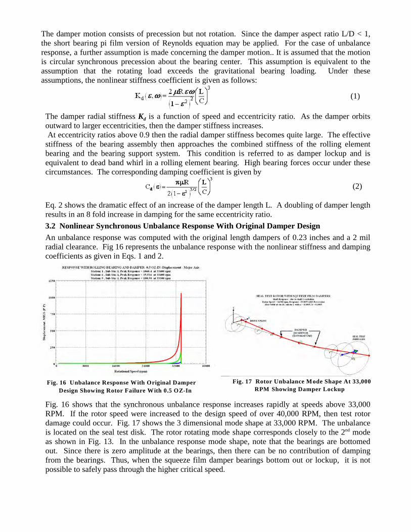
The damper motion consists of precession but not rotation. Since the damper aspect ratio L/D < 1,the short bearing pi film version of Reynolds equation may be applied. For the case of unbalanceresponse, a further assumption is made concerning the damper motion.. It is assumed that the motionis circular synchronous precession about the bearing center. This assumption is equivalent to theassumption that the rotating load exceeds the gravitational bearing loading. Under theseassumptions, the nonlinear stiffness coefficient is given as follows:
(1)
dThe damper radial stiffness K is a function of speed and eccentricity ratio. As the damper orbitsoutward to larger eccentricities, then the damper stiffness increases. At eccentricity ratios above 0.9 then the radial damper stiffness becomes quite large. The effectivestiffness of the bearing assembly then approaches the combined stiffness of the rolling elementbearing and the bearing support system. This condition is referred to as damper lockup and isequivalent to dead band whirl in a rolling element bearing. High bearing forces occur under thesecircumstances. The corresponding damping coefficient is given by
(2)
Eq. 2 shows the dramatic effect of an increase of the damper length L. A doubling of damper lengthresults in an 8 fold increase in damping for the same eccentricity ratio.
3.2 Nonlinear Synchronous Unbalance Response With Original Damper Design
An unbalance response was computed with the original length dampers of 0.23 inches and a 2 milradial clearance. Fig 16 represents the unbalance response with the nonlinear stiffness and dampingcoefficients as given in Eqs. 1 and 2.
Fig. 16 shows that the synchronous unbalance response increases rapidly at speeds above 33,000RPM. If the rotor speed were increased to the design speed of over 40,000 RPM, then test rotordamage could occur. Fig. 17 shows the 3 dimensional mode shape at 33,000 RPM. The unbalanceis located on the seal test disk. The rotor rotating mode shape corresponds closely to the 2 modend
as shown in Fig. 13. In the unbalance response mode shape, note that the bearings are bottomedout. Since there is zero amplitude at the bearings, then there can be no contribution of dampingfrom the bearings. Thus, when the squeeze film damper bearings bottom out or lockup, it is notpossible to safely pass through the higher critical speed.
Fig. 16 Unbalance Response With Original Damper
Design Showing Rotor Failure With 0.5 OZ-In
Fig. 17 Rotor Unbalance Mode Shape At 33,000
RPM Showing Damper Lockup
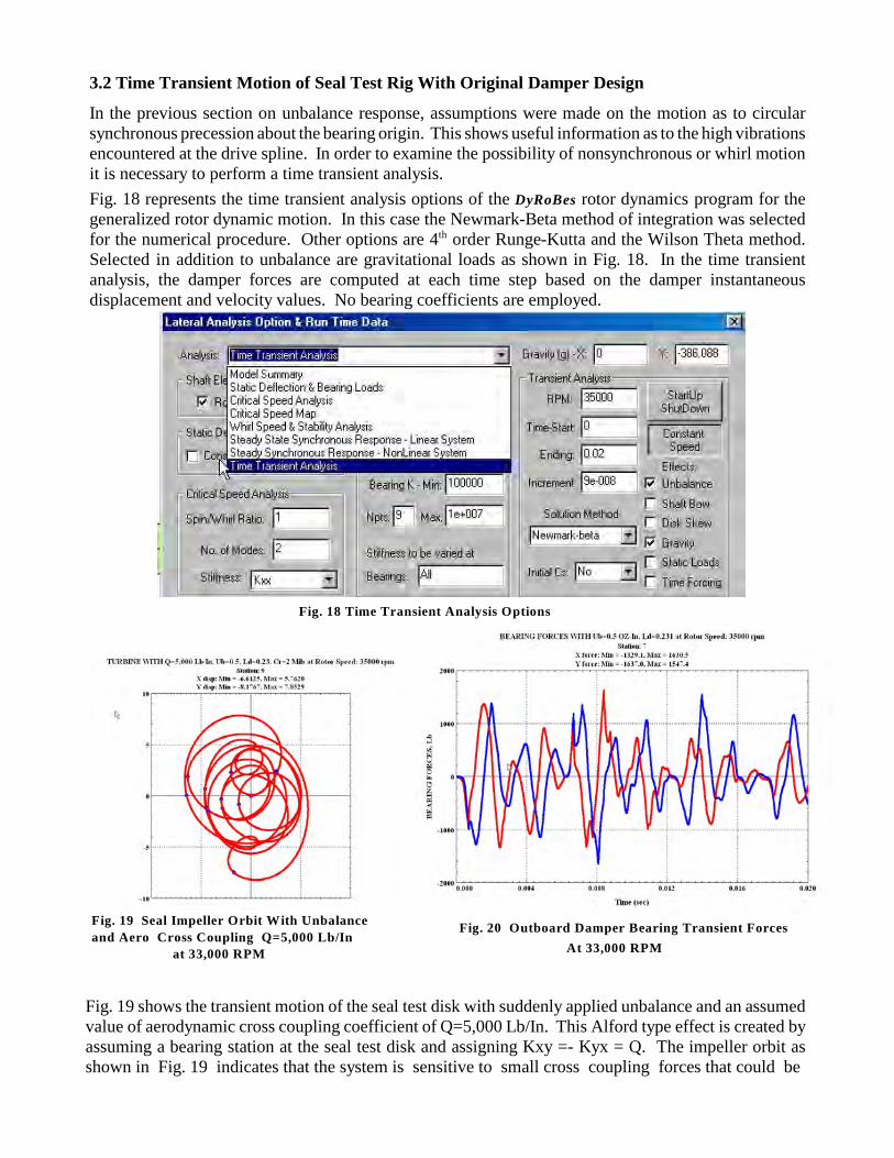
3.2 Time Transient Motion of Seal Test Rig With Original Damper Design
In the previous section on unbalance response, assumptions were made on the motion as to circularsynchronous precession about the bearing origin. This shows useful information as to the high vibrationsencountered at the drive spline. In order to examine the possibility of nonsynchronous or whirl motionit is necessary to perform a time transient analysis.
Fig. 18 represents the time transient analysis options of the DyRoBes rotor dynamics program for thegeneralized rotor dynamic motion. In this case the Newmark-Beta method of integration was selectedfor the numerical procedure. Other options are 4 order Runge-Kutta and the Wilson Theta method.th
Selected in addition to unbalance are gravitational loads as shown in Fig. 18. In the time transientanalysis, the damper forces are computed at each time step based on the damper instantaneousdisplacement and velocity values. No bearing coefficients are employed.
Fig. 19 shows the transient motion of the seal test disk with suddenly applied unbalance and an assumedvalue of aerodynamic cross coupling coefficient of Q=5,000 Lb/In. This Alford type effect is created byassuming a bearing station at the seal test disk and assigning Kxy =- Kyx = Q. The impeller orbit asshown in Fig. 19 indicates that the system is sensitive to small cross coupling forces that could be
Fig. 18 Time Transient Analysis Options
Fig. 19 Seal Impeller Orbit With Unbalance
and Aero Cross Coupling Q=5,000 Lb/In
at 33,000 RPM
Fig. 20 Outboard Damper Bearing Transient Forces
At 33,000 RPM
generated in typical seals. Fig. 19 indicates that the maximum orbit may exceed 8 mils. This could alsolead to seal rubs which can generate super as well as subharmonic frequencies. Fig. 20 shows the transient outboard bearing forces transmitted. These bearing loads are excessive andcan result in diminished rolling element bearing life. The bearing loading is similar to the loadsencountered with a rolling element bearing undergoing dead band whirl with a 2 mil clearance. It isapparent from the unbalance response plot of Fig. 16 and the whirl orbit as show in Fig. 19 that thedampers are insufficient to provide adequate damping for control of seal test disk whirling or control ofthe high amplitude of vibration encountered at the drive spline at the 2 critical speed. nd
4. DYNAMIC ANALYSIS WITH ENHANCED SQUEEZE FILM DAMPERS
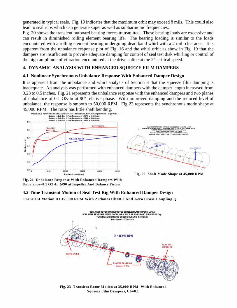
4.1 Nonlinear Synchronous Unbalance Response With Enhanced Damper Design
It is apparent from the unbalance and whirl analysis of Section 3 that the squeeze film damping isinadequate. An analysis was performed with enhanced dampers with the damper length increased from0.23 to 0.5 inches. Fig. 21 represents the unbalance response with the enhanced dampers and two planesof unbalance of 0.1 OZ-In at 90 relative phase. With improved damping and the reduced level ofo
unbalance, the response is smooth to 50,000 RPM. Fig 22 represents the synchronous mode shape at45,000 RPM. The rotor has little shaft bending.
4.2 Time Transient Motion of Seal Test Rig With Enhanced Damper Design
Transient Motion At 35,000 RPM With 2 Planes Ub=0.1 And Aero Cross Coupling Q
Fig. 21 Unbalance Response With Enhanced Dampers With
Unbalance=0.1 OZ-In @90 at Impeller And Balance Piston
Fig. 22 Shaft Mode Shape at 45,000 RPM
Fig. 23 Transient Rotor Motion at 35,000 RPM With Enhanced
Squeeze Film Dampers, Ub=0.1
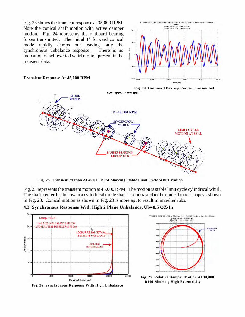
Fig. 23 shows the transient response at 35,000 RPM.Note the conical shaft motion with active dampermotion. Fig. 24 represents the outboard bearingforces transmitted. The initial 1 forward conicalst
mode rapidly damps out leaving only thesynchronous unbalance response. There is noindication of self excited whirl motion present in thetransient data.
Transient Response At 45,000 RPM
Fig. 25 represents the transient motion at 45,000 RPM. The motion is stable limit cycle cylindrical whirl.The shaft centerline in now in a cylindrical mode shape as contrasted to the conical mode shape as shownin Fig. 23. Conical motion as shown in Fig. 23 is more apt to result in impeller rubs.
4.3 Synchronous Response With High 2 Plane Unbalance, Ub=0.5 OZ-In
Fig. 24 Outboard Bearing Forces Transmitted
Fig. 25 Transient Motion At 45,000 RPM Showing Stable Limit Cycle Whirl Motion
Fig. 26 Synchronous Response With High Unbalance
Fig. 27 Relative Damper Motion At 30,000
RPM Showing High Eccentricity
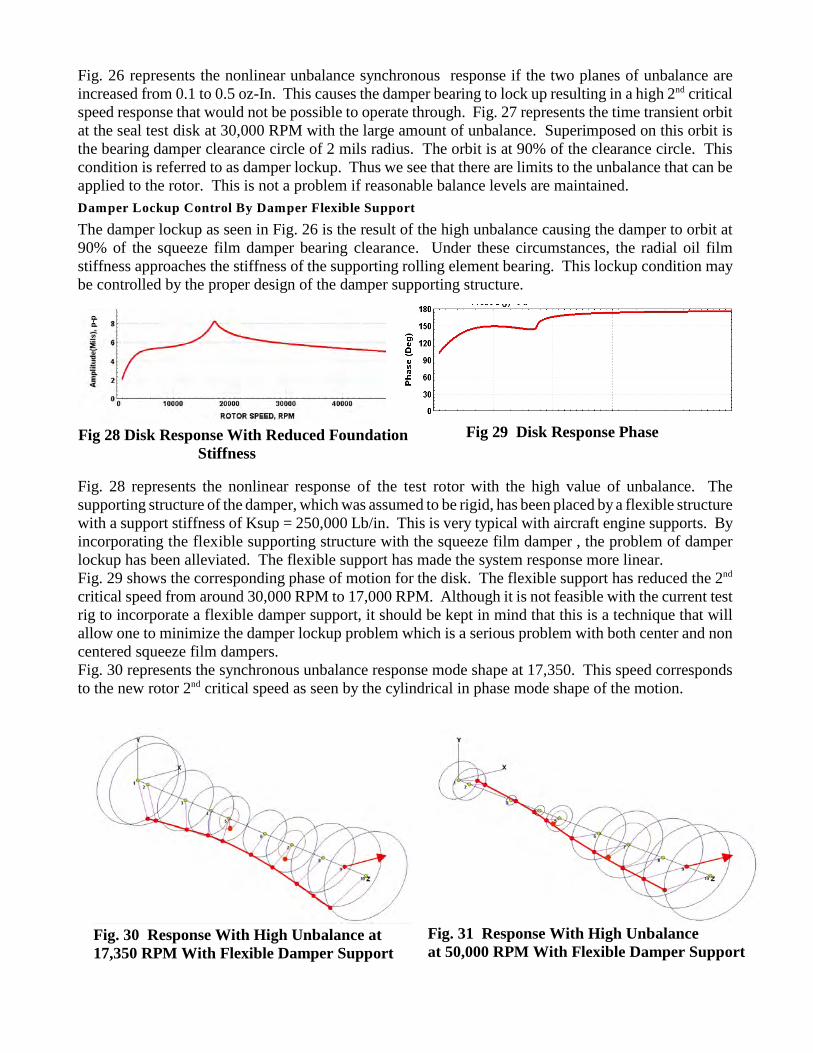
Fig. 26 represents the nonlinear unbalance synchronous response if the two planes of unbalance areincreased from 0.1 to 0.5 oz-In. This causes the damper bearing to lock up resulting in a high 2 criticalnd
speed response that would not be possible to operate through. Fig. 27 represents the time transient orbitat the seal test disk at 30,000 RPM with the large amount of unbalance. Superimposed on this orbit isthe bearing damper clearance circle of 2 mils radius. The orbit is at 90% of the clearance circle. Thiscondition is referred to as damper lockup. Thus we see that there are limits to the unbalance that can beapplied to the rotor. This is not a problem if reasonable balance levels are maintained.
Damper Lockup Control By Damper Flexible Support
The damper lockup as seen in Fig. 26 is the result of the high unbalance causing the damper to orbit at90% of the squeeze film damper bearing clearance. Under these circumstances, the radial oil filmstiffness approaches the stiffness of the supporting rolling element bearing. This lockup condition maybe controlled by the proper design of the damper supporting structure.
Fig. 28 represents the nonlinear response of the test rotor with the high value of unbalance. Thesupporting structure of the damper, which was assumed to be rigid, has been placed by a flexible structurewith a support stiffness of Ksup = 250,000 Lb/in. This is very typical with aircraft engine supports. Byincorporating the flexible supporting structure with the squeeze film damper , the problem of damperlockup has been alleviated. The flexible support has made the system response more linear.Fig. 29 shows the corresponding phase of motion for the disk. The flexible support has reduced the 2nd
critical speed from around 30,000 RPM to 17,000 RPM. Although it is not feasible with the current testrig to incorporate a flexible damper support, it should be kept in mind that this is a technique that willallow one to minimize the damper lockup problem which is a serious problem with both center and noncentered squeeze film dampers.Fig. 30 represents the synchronous unbalance response mode shape at 17,350. This speed correspondsto the new rotor 2 critical speed as seen by the cylindrical in phase mode shape of the motion. nd
Fig 28 Disk Response With Reduced Foundation Stiffness
Fig 29 Disk Response Phase
Fig. 30 Response With High Unbalance at 17,350 RPM With Flexible Damper Support
Fig. 31 Response With High Unbalance at 50,000 RPM With Flexible Damper Support
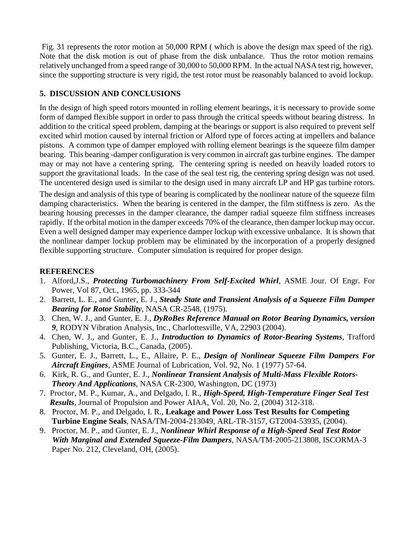
Fig. 31 represents the rotor motion at 50,000 RPM ( which is above the design max speed of the rig).Note that the disk motion is out of phase from the disk unbalance. Thus the rotor motion remainsrelatively unchanged from a speed range of 30,000 to 50,000 RPM. In the actual NASA test rig, however,since the supporting structure is very rigid, the test rotor must be reasonably balanced to avoid lockup.
5. DISCUSSION AND CONCLUSIONS
In the design of high speed rotors mounted in rolling element bearings, it is necessary to provide someform of damped flexible support in order to pass through the critical speeds without bearing distress. Inaddition to the critical speed problem, damping at the bearings or support is also required to prevent selfexcited whirl motion caused by internal friction or Alford type of forces acting at impellers and balancepistons. A common type of damper employed with rolling element bearings is the squeeze film damperbearing. This bearing -damper configuration is very common in aircraft gas turbine engines. The dampermay or may not have a centering spring. The centering spring is needed on heavily loaded rotors tosupport the gravitational loads. In the case of the seal test rig, the centering spring design was not used.The uncentered design used is similar to the design used in many aircraft LP and HP gas turbine rotors.
The design and analysis of this type of bearing is complicated by the nonlinear nature of the squeeze filmdamping characteristics. When the bearing is centered in the damper, the film stiffness is zero. As thebearing housing precesses in the damper clearance, the damper radial squeeze film stiffness increasesrapidly. If the orbital motion in the damper exceeds 70% of the clearance, then damper lockup may occur.Even a well designed damper may experience damper lockup with excessive unbalance. It is shown thatthe nonlinear damper lockup problem may be eliminated by the incorporation of a properly designedflexible supporting structure. Computer simulation is required for proper design.
REFERENCES1. Alford,J.S., Protecting Turbomachinery From Self-Excited Whirl, ASME Jour. Of Engr. For
Power, Vol 87, Oct., 1965, pp. 333-344 2. Barrett, L. E., and Gunter, E. J., Steady State and Transient Analysis of a Squeeze Film Damper
Bearing for Rotor Stability, NASA CR-2548, (1975).3. Chen, W. J., and Gunter, E. J., DyRoBes Reference Manual on Rotor Bearing Dynamics, version
9, RODYN Vibration Analysis, Inc., Charlottesville, VA, 22903 (2004).4. Chen, W. J., and Gunter, E. J., Introduction to Dynamics of Rotor-Bearing Systems, Trafford
Publishing, Victoria, B.C., Canada, (2005).5. Gunter, E. J., Barrett, L., E., Allaire, P. E., Design of Nonlinear Squeeze Film Dampers For
Aircraft Engines, ASME Journal of Lubrication, Vol. 92, No. 1 (1977) 57-64.6. Kirk, R. G., and Gunter, E. J., Nonlinear Transient Analysis of Multi-Mass Flexible Rotors- Theory And Applications, NASA CR-2300, Washington, DC (1973)7. Proctor, M. P., Kumar, A., and Delgado, I. R., High-Speed, High-Temperature Finger Seal Test Results, Journal of Propulsion and Power AIAA, Vol. 20, No. 2, (2004) 312-318.8. Proctor, M. P., and Delgado, I. R., Leakage and Power Loss Test Results for Competing Turbine Engine Seals, NASA/TM-2004-213049, ARL-TR-3157, GT2004-53935, (2004).9. Proctor, M. P., and Gunter, E. J., Nonlinear Whirl Response of a High-Speed Seal Test Rotor With Marginal and Extended Squeeze-Film Dampers, NASA/TM-2005-213808, ISCORMA-3 Paper No. 212, Cleveland, OH, (2005).