Embed Size (px)
Citation preview

®
Where Tradition and Innovation Meet
Conventional TravelTrailer & Fifth-Wheel
Travel Trailer
Owner’s Manual

Cunningham Campers, Inc.5201 Highway 62
Jeffersonville, IN 471301-812-284-0276 Option 3
Welcome to our Used Jayco Owners' Group
We Know Jayco Parts! As a group member you receive 10% OFF any order for parts, not already on sale. Just call us with your VIN # and we will find what you need and ship it directly from Jayco to your front door.
Like Jayco, we are family owned and operated. Our courteous professionals are here to help make your shopping experience as pleasant as humanly possible.
1-812-284-0276Use Option 3 For Parts
http://parts.cunninghamcampers.com/jaycoclubCunningham’s – Selling & Servicing Jayco RV’s for OVER 38 Years!

© 1997 Jayco, Inc. LITHO U.S.A. 00-5 PART NO. 0053067
This manual has been provided by Jayco, Inc. for the solepurpose of providing instructions concerning the operation andmaintenance of this vehicle and its components. Nothing in thismanual creates any warranty, either expressed or implied. The onlywarranty offered by Jayco, Inc. is as set forth in the limited warrantyapplicable to this vehicle.
The owner’s failure to provide required service and/ormaintenance could result in the loss of warranty. The owner shouldreview Jayco’s limited warranty and the limited warranties of allother manufacturers offering them that are applicable to this vehicle.
Instructions are included in the manual for operating variouscomponents which are optional on some vehicles. In addition, theowner should refer to individual manufacturer’s operating instructionscontained in the owner’s packet.
CAUTION: Read all instructions prior to using camper.

YOUR NEW JAYCO IS YOUR PASSPORT TO A WHOLE WORLD OF NEW FRIENDS,CAMPING FUN AND TRAVEL ADVENTURE WHEN YOU JOIN THE THOUSANDS OFJAYCO FAMILIES WHO MAKE UP THE . . .
JAYCO JAFARI INTERNATIONAL TRAVEL CLUB
You will find us enjoying the friendship and fellowship of JAFARI CAMPING as we join ourlocal area FLIGHTS at hundreds of weekend camp-outs all over North America each month . . .
WE’RE THE FAMILIES OF JAYCO!
There are special STATE, REGIONAL and INTERNATIONAL RALLIES where you can joinwith your fellow JAFARIANS and their flights to enjoy a special kind of togetherness . . . fun,games, and entertainment provide memories to last a lifetime.
And . . . how about the exotic surroundings of NEW ORLEANS, the sounds and color ofNASHVILLE and the GRAND OLE OPRY, the roar and rush of the INDIANAPOLIS 500, thequiet surroundings of the CANADIAN ROCKIES, the color of the SMOKY MOUNTAINS inthe Fall. These and many other adventures can be yours when you join the. . .
JAYCO JAFARI INTERNATIONAL TRAVEL CLUB
Fill in the blanks on the reverse side, cut along dotted line and mail along with a check to:
JAYCO JAFARI INT’L TRAVEL CLUB
ATTN: Membership Coordinator
P.O. Box 192
Osceola, IN 46561-0192

Yes, it’s for everyone with a JAYCO RV; young couples just starting out, families spending quality timetogether, the young at heart expanding their life experiences. Whether you belong to another campingclub, have always traveled alone, or are just starting, don’t miss out on one of the most priceless benefitsof being an RV family . . . meet new friends and spend a bit of your camping life with some of the finestpeople you will ever have the opportunity to share a campfire or treasure a moment of golden living witha . . FIFTH-WHEEL TRAVEL TRAILER. . .SPORT UTILITY TRAILER . . . CONVENTIONALTRAVEL TRAILER . . . TYPE C MOTORHOME . . . FOLDING CAMPING TRAILER . . . it doesn’tmatter. If you are a JAYCO RV FAMILY, then you are eligible to become a Jayco Jafari Member.
YOU WILL NEVER BE SORRY YOU MADE THE DECISION!
Your membership entitles you to:• Special international decals for your unit.• The Hitch newsletter with schedules of upcoming events and activities.• A membership roster - containing the names and addresses of current members of the club will
be sent bi-yearly.• Discount Cards for several national theme parks including Six Flags and Busch Corp. Parks.• A special price is available on Wheeler’s Campground Guides.• Discounts with Hertz Rental Car.• Discounts with Coach Net, an emergency roadside service.• Farm & City Insurance has RV insurance available at discounted rates to current Jayco Jafari
International Club members.• All of this, plus the joy of meeting new friends and enjoy Jafari adventures around the country.
Start with the first phase of your camping life...just complete the following application and forward it tothe Jayco Jafari International Travel Club office. Your membership application may also be completedonline, by visiting our website at www.jaycorvclub.com. If you have further questions, contact the cluboffice direct at the website or by calling 800-262-5178. Localcalls can be made to 574-258-0571.
WELCOME TO THE JAFARI FAMILY!
TO: Membership Coordinator for the Jayco Jafari International Travel Club
Please enroll us as members in the Jayco Travel Club. We are ready to roll to where the “friends we justhaven’t met yet” have the coffee on the fire and are waiting for us to arrive: We are ...
Name: Spouse:
Address: Phone:
City: State: Zip:
Email:
Ages of Children at Home:
Our JAYCO is a: Our Dealer(type & size)
Membership Dues:One year $25.00 Amount enclosed. $Two years: $45.00 Check #:Three years: $65.00
(signature) (date)
�

i
Table of Contents
Chapter 1 – Introduction To RV OwnershipWelcome 1Safety Considerations 2
Reporting Safety Defects 2Safety in Using LP Gas 2Electrical System Safety 3Safety When Emergency Stopping 3Additional Safety Considerations 3
Insurance 4Extended Use 4Cold Weather Use 4Condensation 4
Chapter 2 – Obtaining ServiceWarranty Registration 5Service Procedures 7
Basic Service Procedures 7Dealer 7Factory 8Parts 8Owner’s Responsibility 8
Chapter 3 – Using Your Travel TrailerEquipment 9
Tow Vehicle 9Hitches – Conventional Travel Trailer 9The Safety Chain – Conventional Travel Trailers 11Hitches – Fifth-Wheel Travel Trailer 12Towing 12
Traveling 13Weights and Cargo Capacity 13Loading Cargo 14Tires 14Tire Chart 14
Vinyl Tire Covers (Optional) 15Wheel Lugs 16Fire Extinguisher 16Brakes - Electrical 16Breakaway Switch 17

ii
Slideout Room Option 17Operations (Electric Slideout) 18Operations (Manual Slideout – Resort Travel Trailers) 19Operation (Manual Slideout – Qwest Travel Trailer) 20Maintenance 20Troubleshooting Electric Slideout 20Overriding the Electric Main Room/Bedroom Slideout System 21
Setting Up Your Travel Trailer 24Carbon Monoxide Detector (Option) 25
Fifth-Wheel Travel Trailers Only 25Procedures to Take During an Alarm 25Maintenance/Testing 25
TV Antenna 26Raising Antenna to Operating Position 26To Test System 26Lowering Antenna to Travel Position 26Maintenance 26
Chapter 4 – The SystemsPlumbing System 27
City Water Connection 27Gravity Fill Tank 27Fills 2712 Volt DC Demand Pump 28Sanitizing and Filling the Potable Water System 28Faucets 29Bath and Shower 29Outside Shower (optional) 29Drainage 29
Winterizing Travel Trailer 30Sanitation System (Marine Toilets Only) 32
Toilets 32Maintenance 32Residential Stools (Resort Model Only) 33Using Toilet and Tank System 33Vents 33Holding Tanks 33
LP Fuel System 35LP Container 35Servicing and Filling LP Containers 35Main Supply Hose – Low Pressure 37Regulator 38Operation 38Checking for Leaks 39
If You Smell Gas 39LP Gas Consumption 39Automatic Changeover Regulator (Option) 40

iii
LP Detector 40Electrical System 42
General 42Changes, Modifications and Additions 42120-Volt AC System 42
Power Cord 42GFCI 4330-amp Service 4350-amp Service (Optional) 44Consumption of 120-volt AC Power 45
12-volt DC System 45Converter 45Auxiliary Battery (Option) 45Battery Isolator (For Tow Vehicle) 46Exterior Lights 46Porch Light 46
Television Cable 46Fluorescent Lighting (Option) 47Fuse and Bulb Chart 47Brakes 48
Chapter 5 – AppliancesGeneral 49Furnace 49Range and Oven Operation 52Water Heater 53
Pilot Operation 54Electric Ignition Operation 55Pilot Re-ignite Operation 55Electric Operation 56Flushing Instructions 56
Refrigerator - RV Type 57Leveling 57Venting 57Door Seal 57Battery Drain 58Controls 58
N621 and N841 Series Refrigerators 58Door Handles 58Interior Light 58Door Alarm 59Backup Operating System 59Operating the Refrigerator Controls – N621 60Operating the Refrigerator Controls – N841 61Ice Maker 62
Refrigerator - Residential Units 63Monitor Panel (Eagle) 63

iv
Chapter 6 – Care of Body ComponentsExterior Aluminum 65Fiberglass Sidewalls 65Exterior Roof 65Stone Guard 65ABS Plastics 66Frame 66Doors, Extrusions, Windows & Vents 66Furniture 66Bedspreads 67Drapes 67Window Shades 67Pleated Blinds (Designer only) 67Tire Covers - Vinyl (Optional) 67Paneling 67Vinyl Floor 68Wood Floor 68Bathroom Tubs, Lavatory Sinks 68Carpeting 68Countertops 68Hardware and Sink or Shower Fixtures 68
Chapter 7 – Maintenance/StorageSlideout 69Carbon Monoxide Detector 69TV Antenna 70Furnace Maintenance 71Toilets 71Storage 71Mechanical Maintenance Chart 72Maintenance Checklist 76
Chapter 8 – OptionsAir Conditioner 79Generator 79Microwave Oven / Convection Oven 80Rubber Roof 80RV Digital Satellite System 80Spare Tire Carrier 80Ceiling Fan 81Security Lights 81Patio Door 81Towable Transferable Limited Warranty 82Limited Warranty Transfer Application 84

1
CHAPTER 1INTRODUCTION TO RV OWNERSHIP
WELCOMEThank you for purchasing your Jayco Recreation Vehicle and welcome to the world ofrecreation vehicle travel. Your purchase of a Jayco RV allows you to enter this uniqueworld of camping and leisure in a grand style. Your Jayco RV has been designed andengineered to offer you many comforts of home that will make your campingexperience as enjoyable as possible. Jayco recreation vehicles are designed, con-structed and intended to be used as temporary living quarters for recreation,camping and travel uses, all as defined in the bylaws of the Recreation VehicleIndustry Association. Our recreation vehicles are not intended for the hauling ofcargo.
This owner’s manual was prepared to assist you in understanding the proper use andoperation of various containment systems, servicing and maintenance of componentparts, and explanation of your warranty protection. If you are a newcomer to RV travel,you will especially appreciate the suggestions and “shop talk” information to be foundthroughout this manual to help you obtain the most pleasure from the use of your vehicle.
The information in this manual reflects the most current available to us at the time ofpublication. If you find the components in your recreation vehicle vary significantly fromwhat is described in this manual, please disregard that section and follow the instructionsprovided by that particular component manufacturer. You should carefully read andunderstand this owner’s manual which is a supplement to various other instructionssupplied by the manufacturers of separately warranted products.
Keep this owner’s manual in your recreation vehicle for handy reference. Get to knowyour new vehicle and how it operates. You should carefully read and understand theseinstructions and information supplied by manufacturers of separately warranted prod-ucts, since they contain important operating, safety, and maintenance instructions. If youhave questions that are not adequately answered by this manual or other booklets, consultyour dealer. If he cannot satisfactorily answer your questions, he will call our staff orrefer you to us for help.
Every effort has been made to provide you with a safe, dependable product. Your vehiclecomplies with applicable requirements of Federal Motor Vehicle Safety Standards, StateRegulations, Canadian Standards Associations (CSA) where applicable, and complieswith requirements of ANSI Standard A119.2, the nationally recognized “Standard ForRecreation Vehicles – Installation of Plumbing, Heating and Electrical Systems.” TheRecreation Vehicle Industry Association (RVIA) and Canadian Standards Association(CSA) periodically inspect our production line and assist us in maintaining strict compli-ance with installation and safety standards for those systems. Your follow-up withperiodic safety inspections and a program of preventive maintenance is importantfor the continuation of safe and trouble-free operation.
Camping is a great way to relax and enjoy the outdoors with your friends and family.Please remember to tread lightly on our beautiful land and leave only your footprints sothat others may enjoy nature as much as you did.
The Jayco FamilyJayco, Inc.

2
SAFETY CONSIDERATIONSThe terms NOTE, CAUTION and WARNING have specific meanings in this manual.
A NOTE provides additional information to make a step or procedure easier or clearer.Disregarding a NOTE could cause inconvenience, but would not be likely to cause damageor personal injury.
A CAUTION emphasizes areas where equipment damage could result. Disregarding aCAUTION could cause permanent mechanical damage. However, personal injury isunlikely.
A WARNING emphasizes areas where personal injury or even death could result fromfailure to follow instructions properly. Mechanical damage may also occur.
Reporting Safety DefectsIf you believe that your vehicle has a defect which could cause a crash, injury or death,you should immediately inform the National Highway Traffic Safety Administration(NHTSA) in addition to notifying Jayco, Inc.
If NHTSA receives similar complaints, it may open an investigation, and if it finds that asafety defect exists in a group of vehicles, it may order a recall and remedy campaign.However, NHTSA cannot become involved in individual problems between you, yourdealer or Jayco, Inc.
NHTSA Customer Relations Dept.U.S. Department of Transportation Jayco IncorporatedWashington, D.C. 20590 P.O. Box 460, Middlebury, IN 46540Phone: 1-800-424-9393 Phone: 1-877-825-4782 or 1-219-825-0608Washington, D.C. Area: 368-0123 Business Hours: 8:00-5:00 Mon.–Fri. E.S.T.
You can also obtain other information about motor vehicle safety from the Hotline.
Safety in Using LP GasYou should check for leaks at the connections on the LP gas system soon after purchaseand initial filling of LP tanks, and continued periodic checks of the system are recom-mended. Your vehicle was manufactured to provide you with full access to all gas lineconnections. Leaks can be found with a soapy water solution, which does not containammonia or chlorine, applied to the outside of the gas piping connections: the soap willbubble at the leak. DO NOT USE FLAME OR LIGHTED MATCHES TO TEST FORLEAKS. Tightening connections will usually stop leaks. When tightening connections,use two wrenches with oposing torque to prevent twisting of copper tubing. If this doesnot solve the problem, ask an authorized dealer’s service department to make thenecessary tests and repairs.
ALTHOUGH THE MANUFACTURER AND DEALER HAVE PERFORMED TESTSFOR LEAKAGE, THIS CHECK IS RECOMMENDED DUE TO THE VIBRATIONENCOUNTERED DURING TRAVEL.
LP gas is heavier than air therefore leaking gas tends to flow to low places and willsometimes pocket in low areas, such as the floor. LP gas can usually be detected by anidentifiable odor similar to onions or garlic. Never light a match or allow any open flamein the presence of leaking gas.

3
It is very important to have the LP gas turned off during refueling of tow vehicles. Somestates prohibit traveling with LP container(s) open, especially in underground tunnels.
Never allow gas containers to be filled above the liquid capacity indicated on thecontainer. If a container is overfilled, liquid gas may flow through the regulator causing itto freeze and/or introduce a dangerous excessive gas pressure into the lines. In addition, anoverfilled container placed in hot sunlight may expel excess gas through the relief valveand be susceptible to ignition by any nearby open flame.
Electrical System SafetyCircuit breakers and fuses are installed to protect electrical circuits from overloading. Donot make unauthorized changes to circuitry or add on fixed appliances yourself. If youwish to make changes, consult your dealer and he will assist you in obtaining a safeinstallation.
An approved power supply cord has been supplied with the vehicle. Always use thiscord for hook-up to the 120-volt AC source. Note that the cord has a three pin plug,which provides proper grounding through the third (round) pin. Grounding is yourpersonal protection from electrical shock.
WARNING: Do not use an adapter, cheater, or extension cord that willbreak the continuity of the grounding circuit connected to the third pin.NEVER remove the grounding pin to connect a non-grounded, two-prongreceptacle.
Safety When Emergency StoppingPull off the roadway as far as possible for emergency situations and turn on the vehicularhazard lights. If necessary, display your road flags and/or reflective triangular highwaywarning devices.
NOTE: Always carry road flags and/or reflective triangular highway warning devicesto be displayed when necessary.
Additional Safety Considerations• Sanitize the fresh water supply system periodically (see sanitizing instructions).• Prevent water connection fittings from coming in contact with the ground or drain hose
to reduce chance of contamination.• Enlist services of a qualified or certified RV technician to repair and maintain gas or elec-
trical appliances.• Always have a serviceable fire extinguisher placed in an easily accessible location.• Carefully read the section on loading cargo in Chapter 3.• Ensure that tires are in good condition and properly inflated. Proper inflation should be
monitored closely. Neglecting to do so could result in overheating of a tire, which couldresult in a blowout.
• Check and tighten wheel lugs after the first 10 miles, 25 miles, and 50 miles when newand after a wheel has been removed. Check perodically thereafter.
• Check brakes in a safe area - not while traveling a busy highway.

4
• Block travel trailer wheels solidly before unhitching.• Observe the warning labels attached to your vehicle concerning LP gas, water, electric-
ity and loading.• Observe the maintenance chart in Chapter 7 related to your respective unit.
INSURANCEAs with your automobile, it is important that you protect yourself and others withinsurance coverages for personal liability, theft, collision, property damage, etc. Yourdealer will assist you in obtaining appropriate insurance for your protection or you maycheck with the company which provides your automobile insurance.
EXTENDED USEYour new travel trailer has been built for enjoyment in a recreational manner. It is notintended to be used as full-time living quarters.
CAUTION: Continuous living in your travel trailer could cause accelerated wearand damage to components.
COLD WEATHER USE• Use of this travel trailer during cold weather will require more protection. Using skirt-
ing or insulation below floor level will provide additional protection if you are campedin one area for an extended period.
• Proper care should be taken with the fresh water and drainage systems to avoid freezingproblems. Consult your local dealer or RV supply house for advice on heat tapes, etc.
• Adequate gas and electrical supply is needed along with protection from possible freeze-ups on gas regulator. The furnace will substantially increase battery draw and LP use.
• During cool weather usage, ventilation or addition of a dehumidifier may be required toreduce condensation. See next section for important information on controlling con-densation.
CONDENSATIONCondensation is a natural phenomenon. The amount of condensation will vary with theclimate conditions, particularly the relative humidity. Condensation occurs because thereis water vapor present in the air, which is added by breathing, bathing and cooking. Thewater vapor collects where there is available air space, and when the temperature reachesthe ‘dew point’ the water vapor in the air condenses and changes to liquid form. Mostpeople have experienced a similar phenomenon when moisture forms on kitchen windowsand bathroom mirrors during cool weather.
Proper ventilation and, if needed, the use of a dehumidifier will assist in controlling thecondensation. Many RV and marine dealers carry small dehumidifiers especially sized forrecreation use. Condensation causes dampness, mildew, staining and if allowed to con-tinue at high levels, damage to the paneling and wood structures.

5
CHAPTER 2OBTAINING SERVICE
WARRANTY REGISTRATION

6
7
SERVICE PROCEDURES
Basic Service ProceduresWe are interested in your satisfaction. Only by having your complete confidence andsatisfaction with our product and its service can we assure our continued success asmanufacturers of recreation vehicles. We have found that continuing a pleasant andeffective relationship through our dealers is equally as important as maintaining thetechnical excellence of our product. Your authorized dealer will cordially assist you inproviding service, maintenance, selection of options and instructions concerning theoperation of your vehicle.
Should you have a problem with service, please follow these instructions in sequence.
1. Contact your selling dealer’s service department for an appointment. Describe to thebest of your knowledge the nature of the problem.
2. Contact the owner or General Manager of the dealership should the initial attemptfail with the service department.
3. If further assistance is needed contact:Customer Relations Dept.Jayco IncorporatedP.O. Box 460Middlebury, IN 46540Phone: 1-877-825-4782 or 1-219-825-0608Business Hours: Monday – Friday 8:00 – 5:00 EST
Give all the above information as requested along with the serial number of the unit inquestion and we will make every attempt to resolve your problem.
Please bear in mind that most problems arise from misunderstandings concerning war-ranty coverage and service. In most instances, you will be referred to the dealer level andproblems will be resolved with the dealer’s facilities and personnel.
DealerYour authorized Jayco dealer has inspected and serviced your new Jayco travel trailer andis authorized to service and maintain your travel trailer as needed. All warranty repairs areto be performed by the selling dealer unless Jayco gives prior approval.
Some RV dealers may be authorized service centers for certain manufacturers of productswarranted separately. Check with your dealer before contacting others to reduce delays. Ifyour Jayco dealer is not an authorized service center for the product in question, they willbe able to assist you in obtaining authorized service.

8
FactoryA factory service department is operated at our Middlebury, Indiana, manufacturingfacility. Should your Jayco RV be in need of repairs and your dealer recommends that thefactory make the necessary repairs, it may be returned to our plant upon following theseprocedures:
A. You or your dealer must make an appointment prior to returning it to the factoryservice department.
B. All transportation costs are the responsibility of the owner. You may need toarrange for alternative accommodations for some types of repairs. Please be preparedaccordingly.
PartsParts are available at most Jayco dealerships or your dealer can order parts for you asneeded. Should you be unable to find a dealer in your local area, contact our CustomerService Department at 877-825-4782 or 219-825-0608 and we will assist you byproviding parts through an authorized dealer or from Jay-Parr Supply, our parts departmentlocated in Middlebury, Indiana.
Owner’s ResponsibilityAs a new owner of a Jayco recreation vehicle, you are responsible for regular andproper maintenance. This will help you prevent conditions arising from neglectthat are not covered by your Jayco Limited Warranty.
Maintenance service should be performed in accordance with this owner’s manual andany other applicable manuals.
As the owner, it is your responsibility and obligation to return the RV to an authorizeddealer for repairs and service. Reference your Jayco Limited Warranty for additionalinformation. Because the authorized dealer where you purchased your RV is responsiblefor its servicing before delivery and has an interest in your continued satisfaction, werecommend that inspection, warranty and maintenance services be performed by thedealership.
If you are traveling and are unable to locate an authorized Jayco dealer, or an authorizeddealer for the component needing service, please call our customer service office at877-825-4782 or 219-825-0608 or contact your selling dealer for assistance.
NOTE: Service at a non-authorized Jayco dealer should have prior authorization. Youwill be asked to return any mechanical parts replaced before reimbursementconsideration is made. Unauthorized or improper repairs may void thewarranty on that component.
Please keep your owner’s manual, your copy of the warranty registration form and anyother related papers in your RV.

9
CHAPTER 3USING YOUR TRAVEL TRAILER
In this chapter you will find helpful information to assist you in preparing, traveling andusing your travel trailer.
EQUIPMENT
Tow VehicleBegin your camping experiences by using a tow vehicle that will adequately transportyour travel trailer to and from your destinations. You must use the Gross Vehicle WeightRating (GVWR) factor as a measuring tool to match the capability of your selected towvehicle. Most auto and truck manufacturers provide trailer towing guides for theirproducts. Ask your local automotive dealer for a copy or contact the factory’s direct linesfor information. Many tow vehicles, including mini-vans, have special towing packageoptions available for small travel trailers. Because of the sway issue, tow vehicles withlong wheel bases perform better than tow vehicles with short wheel bases. The conditionof the suspension system of your tow vehicle is also an important factor. Make sure yourtow vehicle is in good mechanical condition and maintenance is up to date.
Hitches – Conventional Travel TrailerAfter choosing your tow vehicle, it is very important to install a hitch system withweight distributing bars to accommodate your travel trailer. The selection and installationshould be performed by a professional hitch service which may or may not be yourselling dealer.
A Class IV hitch is suggested. Equalizing bars should be equal to or greater than theGVWR. The very equipment that sometimes gives autos, trucks and sport utility vehiclesa softer ride can accentuate swaying when pulling a travel trailer. Conversely, suspensionthat is too stiff will increase vibration, bounce and accelerate wear of your tow vehicle andtravel trailer. It is important that your travel trailer be level when hitched to your towvehicle. Educate yourself to protect you, your family and other motorists. Short wheelbases on tow vehicles can contribute to sway.
WARNING: We recommend the use of an anti-sway device or swaycontrol for all tow vehicle/trailer combinations.
CAUTIONS:
• Using an oversized or undersized hitch can cause damage to the frame of your traveltrailer.
• Jayco, Inc. cannot be responsible for the suspension system of the tow vehicle.The final ball height after the travel trailer is completely hooked up is a factor tobe considered when towing a travel trailer. To avoid overloading your travel traileraxles and minimize possible handling difficulties, your travel trailer should be levelwhen hooked to your tow vehicle.
• Do not overload your tow vehicle.

10
Hitch Height Specifications - ConventionalTravel TrailerNote: To determine the hitch height for your model, make surethat the travel trailer is level. Measure from inside the hitchcoupler to the ground. Record this number in the box at theside for future reference. The table below contains an averagemeasurment obtained by measuring severl units with differentoptions. This gives you a target range for what your unit willmeasure.
Eagle Designer Qwest Ball Height Ball SizeAll 21" 2-5/16"
302 FK 20-1/2" 2-5/16"312 FKS 21-1/2" 2-5/16"314 BHS 21-1/2" 2-5/16"266 FBS 21-1/2" 2-5/16"296 FBS 21-1/2" 2-5/16"316 FB 21" 2-5/16"264 BH 21" 2-5/16"262 FK 21" 2-5/16"304 BH 21" 2-5/16"246 FB 21" 2-5/16"
3120 FKS 21-1/2" 2-5/16"3320 FKS 21-1/2" 2-5/16"3500 FSS 21-1/2" 2-5/16"
376 FBS 21-1/2" 2-5/16"350 FSS 21-1/2" 2-5/16"
The Hitching Procedure – Conventional Travel TrailerHooking up a conventional travel trailer is not difficult and will become easier withpractice. The following procedure will help you until you become more experienced.
1. Turn crank on jack to raise tongue of travel trailer above hitch ball on hitch.2. Open coupler latch on travel trailer hitch.3. Back tow vehicle into proper position.4. Turn crank on jack to lower coupler onto ball hitch.5. Close coupler latch after completely seated.6. Install weight distributing bars (equalizers) as per recommendations from hitch
supplier, when required.7. Remove dolly wheel and retract tongue jack to its maximum height.8. Attach breakaway switch cable to tow vehicle.9. Attach safety chains as shown in Figure 3-1.
10. Plug in your 12-volt DC electrical connector from tow-vehicle to travel trailer.11. The following items should be inspected prior to your journey:
• All lights should be in working order.• Stabilizer jacks should be in the retracted position.
This unithitch height
is:

11
• Entrance steps should be in the retracted position.• Refrigerator door should be closed and locked.• All loose items should be secured.• Brakes should be tested for operation prior to entering roadway.• Tire pressure should be checked and maintained per the tire pressure stamped on
the tire sidewall.
The Safety Chain – Conventional Travel TrailersThere are different safety chain requirements determined by the various state laws. Yourvehicle is equipped with chains to meet SAE standard requirements for maximum grosstrailer weight. Always have the safety chains attached when towing. Install them asshown below so they do not restrict sharp turns, but tight enough so they do not drag onthe ground.
Fig. 3-1

12
Hitches – Fifth-Wheel Travel TrailerDifferent types of hitches are available for pickup trucks to tow fifth-wheel traveltrailers. The best type of hitch is one that is bolted directly to the floor of the truck boxthrough the frame members.
Another type of hitch is the mini-hitch. The mini-hitch has two brackets attached to thetruck box, and is placed over the fender. This type of hitch generally does not provideframe support for strength.
Hitch Height - Fifth-Wheel Travel TrailerThere is no recommended hitch height for fifth-wheel travel trailers. The pin box isadjustable at two inch intervals for variance in trucks and their suspension systems.Always travel with the truck and travel trailer as level as possible.
The Hitching Procedure – Fifth-Wheel Travel Trailer1. Make sure the hitch lever is in its open or “cocked” position unless it has been
designed to open automatically.2. Back the truck so the hitch encircles the fifth-wheel travel trailer pin.3. A gentle contact of the hitch saddle against the pin will cause the mechanism to
close.4. Secure the hitch lever as specified by manufacturer.5. Be sure to raise the fifth wheel landing gear all the way up.6. Attach breakaway switch cable to tow vehicle.7. Plug the 12-volt DC electrical connector from tow vehicle to fifth-wheel travel
trailer.8. Raise the tailgate of tow vehicle, if applicable.9. When unhitching, make sure you do not forget to lower the tailgate.
TowingWhile towing your Jayco travel trailer, you need to be aware of the extra weight behindyour vehicle. The following list contains some pointers to remember while traveling.
• With the travel trailer attached, you will have slower acceleration and require greaterdistance to stop.
• Make sure you have enough area at corners when turning. Wider turns are necessary. Useyour turn signals for your own safety.
• When passing or changing lanes, take into consideration the overall length of your traveltrailer and allow ample distance and time.
• Use your rearview mirrors frequently to observe your travel trailer and traffic conditions.• When being passed by a large truck or bus, be prepared for displaced air as it may cause
you to sway slightly.• Upon climbing steep, long grades and again descending, use lower gears even before it
seems necessary. Use your brakes smoothly and evenly.• Drive slowly during wet and icy conditions to ensure better control of your vehicle.

13
• Check all exterior lights before each trip.• Obey traffic laws, allow extra time for stopping and decrease speed when visibility is
limited or roads are wet.• Have a safe and wonderful trip!If towing a trailer is new for you, please take time to practice towing, parking and backingskills prior to traveling. Your dealer can answer many of your questions, but nothingreplaces practice. We recommend you find a large and quiet parking lot to practice yourskills.
TRAVELINGWeights and Cargo CapacityFor safety reasons, it is very important toprovide RV owners with the most accurateweight information available. The “FederalCertification” label, located on the roadsidefront corner of the sidewall, supplies a por-tion of this information.
There are four important weight terms anowner needs to understand when operating atowable recreation vehicle.
Gross Vehicle Weight Rating (GVWR) –The GVWR equals the most or maximum weight your recreation vehicle should weighwith all liquids (water, LP gas), food, clothing, camping supplies and ALL OPTIONSloaded in the coach when attached to the tow vehicle. The sum of the empty travel trailerweight plus cargo cannot exceed the GVWR.
Unloaded Vehicle Weight (UVW) – The UVW, also called the “Empty ShippingWeight” is the weight of the coach as it was manufactured at the factory without liquids,factory options or dealer accessories included.
Net Carrying Capacity (NCC) – The NCC equals the maxiumum weight of all liquids,options dealer installed options and owner’s cargo consisting of food, clothes, campingequipment, etc.
Gross Axle Weight Rating (GAWR) – The maximum weight that may be placed on anaxle assembly. The sum of this rating is the weakest link of the tires, wheels, springs,axles, or brakes.
The weight provided in the Jayco literature for your travel trailer is based on standardequipment on that particular model and is “dry” (i.e. no liquids or cargo). Remember thatany options or personal cargo added must be subtracted from the available cvargocapacity. Never exceed the gross vehicle weight rating of your travel trailer.
WARNING: Do not add accessories or components that are not safe andappropriate for this product. Jayco, Inc. DOES NOT provide warranty cover-age for equipment installed by dealer or owner for such modifications oradditions. Any such modifications effect weight specifications.

14
Loading CargoPacking equipment requires serious consideration. All cargo should be distributed evenlywith the heaviest items stored in the lower cabinets. Heavy items must be secured toprevent weight shifts during travel. Additional weight behind the axle should be kept to aminimum.
CAUTION: DO NOT overload your travel trailer. Please follow the GVWR whenloading your Jayco travel trailer.
When loading is completed, it is strongly suggested that you drive to a large scale andhave your travel trailer weighed. If you are over loaded, it is advisable that you removesome of your cargo or liquids.
WARNING: The rear bumper on the frame of conventional travel trailersand fifth-wheel travel trailers is not designed to carry over 100 pounds.Never add items such as generators, motorcycle racks, heavy tool boxes, etc.to the back of your travel trailer. Installation of items exceeding 100 poundscould cause metal fatigue and weld stress. DO NOT tow a trailer behindyour travel trailer. Your trailer frame and bumper are NOT designed to towanother trailer.
CAUTION: Damage from add-on equipment or improper loading is not coveredby your Jayco Limited Warranty.
TiresThe tires on all Jayco travel trailers are designed and built for recreational use. Tires areradial in design, having two steel cords and two polyester cords, offering excellentstrength and mileage in all kinds of weather, when used as designed. See brochure inowner’s packet.
NOTE: Tires are warranted by the tire manufacturer and are to be serviced and warrantedby a service center. They are not to be returned to the dealer or travel trailer manufacturer.
Tire ChartCONVENTIONAL TRAVEL TRAILERS Tire Load Max LoadEagle Designer Qwest Size Range Per Tire
264 BH 240A ST205/75R15 C 1820262 FK 244B ST205/75R15 C 1820302 FK 270C ST205/75R15 C 1820316 FB 256D ST205/75R15 C 1820304 BH 294J ST205/75R15 C 1820246 FB ST205/75R15 C 1820314 BHS ST225/75R15 C 2150266 FBS ST225/75R15 C 2150296 FBS ST225/75R15 C 2150312 FKS 3120 FKS ST225/75R15 D 2540376 FBS 3320 FKS ST225/75R15 D 2540350 FSS 3500 FSS ST225/75R15 D 2540

15
FIFTH-WHEEL TRAVEL TRAILERS Tire Load Max LoadEagle Designer Qwest Size Range Per Tire
269 RD 237A ST205/75R15 C 1820255 BH 265B ST205/75R15 C 1820253 RK 231C ST205/75R15 C 1820277 RBS ST225/75R15 C 2150243 RKS ST225/75R15 C 2150313 RKS 3030 RKS ST225/75R15 D 2540263 RKS 2930 RKS ST225/75R15 D 2540285 BHS 2730 RKS ST225/75R15 D 2540293 RKS ST225/75R15 D 2540311 RLS ST225/75R15 D 2540325 BHS ST225/75R15 D 2540
3530 RKS LT215/85R16 E 26803110 RLS LT215/85R16 E 26803710 RL TS LT235/85R16 E 30413410 RL TS LT235/85R16 E 30423610 RL TS LT235/85R16 E 30423310 RLS ST215/85R16 E 26803230 RKS ST215/85R16 E 2680
The air pressure must be kept at its suggested pressure because the weight capacity isrelated to tire pressure. Always check the tires when they are cold; such as beforetraveling at the beginning of the day. It is normal for air pressure to increase whentraveling as tires will heat up. DO NOT release air pressure as tires become hot. If youdo, the tires will then be under-inflated when they cool down.
Examine your tires frequently for unusual wear. Alignment, balance and bearing wear willeffect tire wear.
CAUTION: It is recommended that the tire pressure be checked at the beginning ofeach journey to obtain the maximum life of the tires.
Inflation: Always follow inflation guidelines printed on sidewall of tire.
VINYL TIRE COVERS (Optional)Tip: To minimize the possibility of the tire “bleeding” through onto the tire cover, use aseparator (garbage bag, paper, cloth, etc.) between the tire and the tire cover.

16
WHEEL LUGSWhen the wheels are installed on your Jayco travel trailer, the lug nuts must be tightenedat 90-120 foot pounds of torque.
WARNING: Axles on travel trailers do not drive or steer like automobileaxles. The motion involved in being “trailered” adds stress that can loosenlug nuts, especially during the break in period. Wheel lugs can work loose.Check and tighten wheel lugs every 10 miles, 25 miles and 50 miles whenthe camping trailer is new or a tire is changed, and then check and tightenevery 3,000 miles.
After your first trip, check the wheel lugs periodically for safety. The wheel lugs shouldthen be checked after winter storage, before starting a trip or following extensive braking.Size of bolts or nuts is 13/16". Over torquing wheels is as dangerous as undertorquing.
FIRE EXTINGUISHERA fire extinguisher is installed near the entrance door in the travel trailer. Be familiar withits location and operating instructions as printed on the extinguisher. It is too late tobecome familiar with an extinguisher when an emergency is at hand.
The fire extinguisher is a dry chemical, non-refillable extinguisher. Do not test thisextinguisher. Doing so will cause loss of pressure making the extinguisher unusable. Theextinguisher must be discarded and replaced by a new one if any use has occurred.
BRAKES - ELECTRICALThe electric brakes on your travel trailer are designed to work in conjunction with thehydraulic brakes on your tow vehicle. To have the best brake performance on bothsystems, the travel trailer and tow vehicle must perform and operate together. Anyattempt to use either brake system alone will cause accelerated wear and damage.
A controller should be installed below the dashboard of your tow vehicle to work inconjunction with the travel trailer brakes. Two types of controllers are available. The“hydraulic” controller operates through a steel line attached to the master cylinder of thetow vehicle’s brake system. The “electronic” controller, operates using electrical current.Reference the operating instructions provided with the controller for adjustment andoperation procedures.
The battery in the tow vehicle is the primary power source that operates the brakes inyour travel trailer. Keep your battery and charging system in working operation to ensureavailable energy when required.
From the battery, power is sent to the controller to provide the correct amount of currentto brake the travel trailer. Use the tow vehicle’s brake pedal for general operation oncombined use of both brake systems. The controller’s manual control is to be used onlyin special situations, such as slow movement or icy road conditions. In the open position,the manual control breaks the electrical current preventing brake engagement. When in theclosed position, electrical current will flow to brake assemblies.
Wiring to operate your brakes must be sized in both vehicles, suggesting a minimum of

17
14 gauge. Your travel trailer has 14 gauge from front end to brakes. Brake assemblies arewired in parallel, never in a series. Being parallel, there will be equal voltage and amperageat each brake assembly for equal braking capability and/or performance.
WHEN YOUR TRAVEL TRAILER IS NEW IT IS IMPOSSIBLE TO ADJUSTYOUR BRAKE SHOES PRECISELY. IT TAKES APPROXIMATELY 1000 MILESAND/OR 50 MEDIUM TO HEAVY STOPS TO “BURNISH” FIT OR SEATTHE SHOES TO THE BRAKE DRUM. AFTER THIS INITIAL BREAK-INPERIOD, YOU MUST ADJUST YOUR SHOES ACCURATELY FOR BESTPERFORMANCE AND INCREASED DURABILITY.
BREAKAWAY SWITCHThe breakaway switch is one of the most important parts of the travel trailer electricbrake system. This system will apply the brakes of the travel trailer should it break awayfrom the tow vehicle. The very instant a breakaway occurs, the pull pin, which is linkedto the tow vehicle is pulled from the switch. The two contacts automatically close tocomplete the electrical circuit and apply the travel trailer brakes. A 12-volt DC battery isrequired to power the breakaway switch.
Fig. 3-2
WARNING: NEVER use this breakaway switch and travel trailer brakesystem as a parking brake. There would be a high amp draw on battery andconvertor, potentially causing damaged wiring, connectors, and breakawayswitch.
SLIDEOUT ROOM OPTIONThe slideout room is designed for additional floor space and comfort. Mechanicalcomponents are gear driven and produced by Power Gear Company. Read ALL instructionsin the next four pages before operation to become familiar with the system.
CAUTION: Do not place excessive weight in the slideout room.
ComponentsThis slideout system has numerous major components and are as follows:
• One inner rail drive assembly to support room weight.• A 12-volt DC motor and drive shaft that will operate the room using energy from an on-
board recreation vehicle battery.• A specially designed auto reset fuse has a load sensing capability that stops the motor
when the room reaches its fully extended or retracted position.

18
• A manual override system that allows you to move the room in or out in the event ofa power loss.
• A master switch to keep power from going into the module board, preventing any pos-sible movement until you choose to move slideout.
WARNING:• Ensure that the travel trailer is level before operating the slideout room.• Ensure there are no people or obstructions blocking the path of the room when it
is moving.• Keep away from the slide rails when the room is in motion.• The gear assembly may pinch or catch on loose clothing causing personal injury.• Always install travel bars for storage and transportation.• Ensure the slideout is in the closed position prior to hooking the unit to the tow
vehicle.Failure to follow these instructions
could result in serious injury or death.
Operations (Electric Slideout)
EXTENDING ROOM1. Batteries must be fully charged and connected. The travel trailer should be hooked
up to 120-volt AC power if possible.2. The travel trailer must be level and the stabilizer jacks in the down position.
CAUTION: Additional support jacks are not needed under the slideout. Damagecan occur to your slideout room from improper use of support jacks.
3. Remove the “travel bars” from behind the top facia board located aboveslideout room.
4. Locate master switch on the slideout room control panel.
WARNING: Slideout Master Switch MUST BE in the off position unlessoperating the slideout in or out. Failure to keep the slideout master switchin the off position while not in use could result in vehicle damage orpersonal injury.
5. To move room out, press the “OUT” button on switch and hold until motor stops.Release button. Travel time – approximately twenty seconds.
6. Turn master switch “OFF.”
19
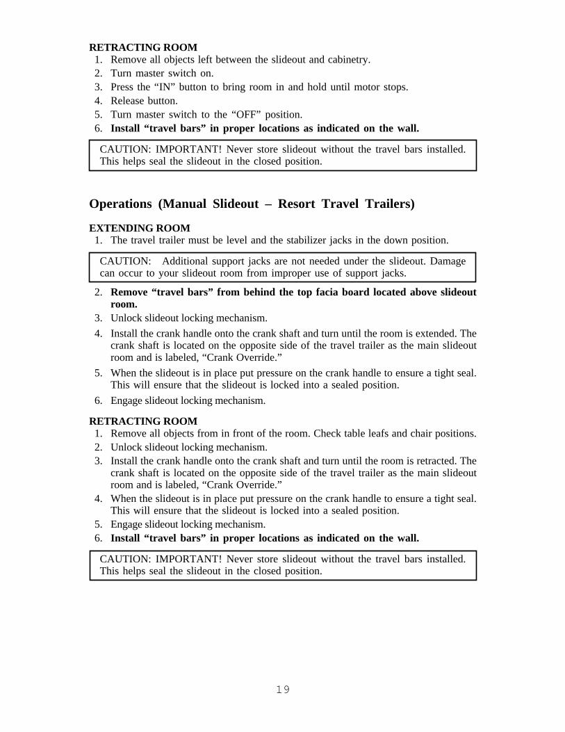
RETRACTING ROOM1. Remove all objects left between the slideout and cabinetry.2. Turn master switch on.3. Press the “IN” button to bring room in and hold until motor stops.4. Release button.5. Turn master switch to the “OFF” position.6. Install “travel bars” in proper locations as indicated on the wall.
CAUTION: IMPORTANT! Never store slideout without the travel bars installed.This helps seal the slideout in the closed position.
Operations (Manual Slideout – Resort Travel Trailers)
EXTENDING ROOM1. The travel trailer must be level and the stabilizer jacks in the down position.
CAUTION: Additional support jacks are not needed under the slideout. Damagecan occur to your slideout room from improper use of support jacks.
2. Remove “travel bars” from behind the top facia board located above slideoutroom.
3. Unlock slideout locking mechanism.4. Install the crank handle onto the crank shaft and turn until the room is extended. The
crank shaft is located on the opposite side of the travel trailer as the main slideoutroom and is labeled, “Crank Override.”
5. When the slideout is in place put pressure on the crank handle to ensure a tight seal.This will ensure that the slideout is locked into a sealed position.
6. Engage slideout locking mechanism.
RETRACTING ROOM1. Remove all objects from in front of the room. Check table leafs and chair positions.2. Unlock slideout locking mechanism.3. Install the crank handle onto the crank shaft and turn until the room is retracted. The
crank shaft is located on the opposite side of the travel trailer as the main slideoutroom and is labeled, “Crank Override.”
4. When the slideout is in place put pressure on the crank handle to ensure a tight seal.This will ensure that the slideout is locked into a sealed position.
5. Engage slideout locking mechanism.6. Install “travel bars” in proper locations as indicated on the wall.
CAUTION: IMPORTANT! Never store slideout without the travel bars installed.This helps seal the slideout in the closed position.

20
Operation (Manual Slideout – Qwest Travel Trailer)
EXTENDING ROOM1. Release the travel lock behind the center door of the overhead cabinets located above
the sofa.2. Release second travel lock located below the sofa.3. For one-person operation, push slideout into the extended position by pushing on
sofa. For two-person operation, push each side of slideout until the slideout locks inplace. Loud clicking of the slideout at this point is normal.
RETRACTING ROOM1. Lift sofa skirt.2. Push up on release handles and pull slideout to the retracted position.3. Lock bottom travel lock.4. Lock top travel lock.
MaintenanceSee “Slideout” section under Maintenance in Chapter 7.
Troubleshooting Electric SlideoutIf the slideout does not move when the slideout switch is depressed, follow these steps.1. Make sure the ON/OFF switch is in the correct position.2. Check the battery for full charge and good wire connections.3. Check for loose connections on the slideout controller located behind kitchen
drawers.
If slideout still will not operate, follow these steps.1. If the slideout is extended, see the section on overriding the electric slideout system.2. If the slideout is retracted, leave it in that position and install the “travel bars.”3. Take the trailer to the nearest dealer or service center.
If the slideout extends crooked, or only one side moves, follow these steps.1. Follow steps 1-4 in the section on overriding the slideout system to disconnect the
motor.2. Retract slideout using the hand crank. You may need to push the side that is not
sliding to get it to retract all the way.3. Once the slideout is fully retracted, install the “travel bars.”4. Take your travel trailer to nearest dealer or service center.

21
Overriding the Electric Main Room/Bedroom Slideout SystemThe Power Gear slideout system is equipped with a manual crank override that allowsyou to extend or retract the room if there is a loss of power.
If the system will not move when the switch is pressed, check the following:• Is the system turned on?• Is the battery connected and does it have a full charge?• Are the travel bars removed?
After checking the above, follow these steps to move the slideout manually.Tools required:• ScruLox head screwdriver (if trailer has an underbelly)• Crank Handle (included with unit)• 1/2" wrench• Adjustable Wrench (for bedroom slideout only)
MAIN ROOM SLIDEOUT OVERRIDE1. Make sure that the ON/OFF switch for the
system is turned “OFF.” The override willnot work if the switch is turned “ON.”
2. If the travel trailer has an underbelly, locateand remove the access panel for the motor.The motor is located just inside the roadsidemain rail. (Fig. 3-4)
3. From the rear of the motor, rotate the brakerelease lever on the back side of the motorcounter-clockwise 1/8 turn. (Fig. 3-3) Thiswill release the brake that locks the slideoutin place.
4. Locate the quick disconnect on the red motor wire and disconnect. (Fig. 3-5 and Fig.3-6) If the motor wire does not have a quick disconnect, locate the red wire comingout of the motor and cut it 4 to 6 inches from the motor.
5. The slideout is now free to move. Install the crank handle onto the crank shaft andturn until the room is in the position you desire. The crank shaft is located on theopposite side of the travel trailer as the main slideout and is labeled, “CrankOverride.” (Fig. 3-4)
6. When the slideout is fully extended (or retracted) have one person put pressure onthe crank handle to ensure a tight seal while another person returns the brake releaselever on the back of the motor to its normal downward position. This will ensurethat the slideout is locked into a sealed position.
7. Re-connect the motor wire quick disconnect. (Fig. 3-5 and Fig. 3-6)8. Install the travel bars and take the unit to a Jayco dealer for service.
WARNING: When the main slideout motor brake is released the slideoutwill not lock into place, and therefore it will not be sealed from theoutdoors! When the slideout has been retracted, be sure to install the travelbars and return the break release lever to its downward position in order toseal and lock the slideout.
Fig. 3-3

22
Fig. 3-4
BEDROOM SLIDEOUT OVERRIDEFifth-Wheel Travel Trailer Option1. Make sure that the ON/OFF switch for the system is turned “OFF.” The override
will not work if the switch is turned “ON.”2. Lift up the mattress and baseboard to gain access to the slideout unit. (Fig. 3-3)3. From the rear of the motor, rotate the brake release lever on the back side of the
motor counter-clockwise 1/8 turn. (Fig. 3-3) This will release the brake that locksthe slideout in place.
4. Locate the quick disconnect on the red motor wire and disconnect. (Fig. 3-5 and Fig.3-6) If the motor wire does not have a quick disconnect, locate the red wire comingout of the motor and cut it 4 to 6 inches from the motor.
5. Use an adjustable wrench on the square end of the drive shaft and turn the shaft untilthe slideout is in the position you desire. When the slideout is fully extended (orretracted), put pressure on the crank handle to ensure a tight seal then return thebrake release lever to its normal downward position. This will ensure that theslideout is locked into a sealed position.
6. Re-connect the motor wire. (Fig. 3-5 and Fig. 3-6)7. Install the travel bars and take the unit to a Jayco dealer for service.

23
Fig. 3-5
Fig. 3-6

24
SETTING UP YOUR TRAVEL TRAILERSelect a level or nearly level place to set up your travel trailer. There are two reasons tobe level. First, all components in your travel trailer are designed to operate in a levelposition, such as your water drainage system and especially your refrigerator. Second, itis more comfortable. Should a level site not be available, use short 2" x 6" blocks of woodto raise the low side wheels to a level position.
Before unhooking the travel trailer from tow vehicle, always mount the dolly wheel totongue jack and block the travel trailer wheels to keep the travel trailer from rolling away.
1. Release weight distributing bars (if used).2. Release safety latch on coupler.3. Raise coupler on A-Frame by turning tongue jack until ball is free.4. Disconnect 7-way wire connector, safety chains, and breakaway cable.5. Move tow vehicle away as desired.6. Lower or raise tongue jack until travel trailer is level.7. Lower stabilizer jacks by placing the crank onto the jack shaft and turning clockwise
to lower it until the frame of the travel trailer begins to rise slightly. Equalize all fourjacks for best support. You may need to adjust each jack two or three times. Forconvenience when you are not parked on cement, you may wish to place a wood orhard plastic block under the jack.
CAUTION: DO NOT USE THE STABILIZER JACKS TO LEVEL THE UNIT. Itis important to remember that stabilizer jacks are to be used only for support whileoccupying and moving around in your travel trailer. They are not designed to bearthe weight of the travel trailer.
Upon completing the setup of your travel trailer, you are now ready to make attachmentsto various facilities as listed:
• Waste water hose connections• 110-Volt power cord electrical hookup• Turn on LP propane tanks and light pilot lights on any appliances. Remember there may
be air in your LP propane lines. Be sure to bleed them before planned usage.• Open any windows and roof vents as desired for ventilation.You may have additional accessories and options such as an awning on the door sidewhich need to be opened. Separate instructions are provided by the manufacturer of thecomponent.
See the process to follow before departing from your campsite under the hitchingprocedures listed earlier in this chapter.

25
CARBON MONOXIDE DETECTOR (Option)
Fifth-Wheel Travel Trailers OnlyIf your towable RV has a generator or generator prep, a carbon monoxide detector will beinstalled on your unit.
Carbon monoxide (CO) is an odorless, colorless, tasteless gas that is extremely dangerousto humans and animals. The following symptoms are indicative of individuals exposed tocarbon monoxide:
Mild Exposure: Slight headache, nausea, vomiting, fatigueMedium Exposure: Severe headache, drowsiness, confusion, fast heart rateExtreme Exposure: Unconsciousness, convulsions, cardiorespiratory failure, death
A UL listed carbon monoxide detector has been installed in your camper. It is designed todetect toxic CO fumes. It is not a substitute for other combustible gas, fire or smokealarms.
Procedures to Take During an AlarmWARNING: The activation of the CO detector is a warning that indicatesthe presence of carbon monoxide!
WARNING: Do not disconnect the CO detector to silence the alarm. Thedetector is designed to sense when the level of CO in the air falls below thedanger level. All individuals should remain outside the unit until the alarmis silent.
• If someone is suffering from an upset stomach, headache or other symptom, immediatelymove to a location that has fresh air. Ensure that everyone is accounted for, includingpets. Call the Fire Department. Do not reenter the unit until the source of carbon mon-oxide has been located and repaired by a qualified technician.
WARNING: Low levels of CO have been linked to brain and vital organdamage to unborn infants with no effect on the mother. Pregnant womenshould leave the unit immediately if an alarm is sounded and not returnuntil the unit has been repaired and aired out thoroughly.
• If no one exhibits the symptoms associated with carbon monoxide:1. Push reset button.2. Turn off all sources of combustion including water heater, furnace, stove, oven, and
automobile.3. Open windows and doors and move to a location that has fresh air.4. Call a qualified technician and have the problem corrected before restarting appli-
ances and/or vehicles.
Maintenance/TestingSee “Maintenance and Testing” instructions in Chapter 7. Additional information issupplied in the manual published by the manufacturer of the equipment.

26
TV ANTENNARaising Antenna to Operating PositionTurn elevating crank clockwise in UP direction about 13 turns or until some resistance toturning is noted. (Fig. 3-8)
On Amplified models, 12-Volt DC power is required. Turn power supply ON to useeither front or rear TV outlet. (Fig. 3-9) Neither outlet will work unless power supplyswitch is on. Turning power supply on sends 12-volt DC up cable to antenna. Voltageenergizes transistors on amplifier in antenna head. TV signal comes back down cable tooutlets.
After antenna is in full UP position, pull down on round knob with both hands until itdisengages from ceiling plate. Rotate for best picture. (Fig. 3-10)
To Test System1. Make sure TV set is working properly.2. Switch power supply ON and OFF to see if there is
a difference in the picture quality while watching TV.If NO difference, refer to manufacturer’s manual forfurther testing procedures.
CAUTION: The power supply should be turned OFFwhen connecting/disconnecting cables to power supply and antenna, but should beturned ON when testing for voltage.
Lowering Antenna to Travel PositionRotate antenna until pointer on directionalhandle aligns with pointer on ceiling plate.Turn elevating crank counterclockwise inDOWN direction about 13 turns or untilresistance is noted. Antenna is now locked intravel position. (Fig. 3-11)
CAUTION: When lowering the antenna, never lower it into any position exceptthe TRAVEL POSITION. Failure to lower antenna into the TRAVEL POSITIONbefore traveling may damage the antenna and is not covered by warranty.
MaintenanceSee “TV Antenna Maintenance” in Chapter 7.
Fig. 3-10
Fig. 3-11
Fig. 3-9
Fig. 3-8
WARNING: DO NOT con-nect high current devices suchas hair dryers to this recep-tacle. Maximum current rat-ing of this receptacle is 7.5amps at 12-volt DC.

27
CHAPTER 4THE SYSTEMS
PLUMBING SYSTEMIncluded in your Jayco recreation vehicle is a complete fresh water system. Fresh watermay be maintained through two sources: city water connection or gravity fill tank. Eachcomponent is explained along with its operation.
Fig. 4-1 Fig. 4-2 Fig. 4-3
City Water ConnectionWater may be received into the system through a direct hookup referred to as the citywater connection. (Fig. 4-2 or 4-3) After hooking up water hose to travel trailer, openvalve on supply line. Enter coach and open faucets to bleed air from lines. Water will fillwater heater first before supplying lines and faucets. When lines are almost full, you mayexperience some air pockets. Allow them to escape before closing faucets.
CAUTION: Excessive pressure from water supply systems may be encountered insome parks, especially in mountain regions. Water pressure regulators are availableto protect your system against such high pressure. A regulator of this type isrecommended to prevent damage to plumbing systems or components. A 45-poundrating is suggested. Not using a water pressure regulator when using city water maycause the o-rings to blow. It is advisable to always use a water pressure regulatorwhen using the city water connection.
Gravity Fill TankA water container is permanently installed in your recreation vehicle. On some models itis located inside the travel trailer under a bed, dinette, or sofa. Other models may have anexternal tank under the floor between frame members.
FillsThere are two types of gravity fill connections to the fresh water tank. Fig. 4-1 is thetype found on most models. Fig. 4-2 has a combination of gravity fill and city waterconnection enclosed which requires a key to gain access.

28
The fresh water tank can be filled by removing the gravity fill cap and inserting a gardenhose. Open faucet from water supply and fill tank. You must be careful not to over filltank. This can pressurize the tank, causing leakage and water damage.
CAUTION: DO NOT leave tank unattended while filling.
12 Volt DC Demand PumpWhen water is desired and you are not hooked up to city water connection, you need toturn on 12 volt DC power to start the demand pump. The switch is located on themonitor panel or a wall near the pump. Energy for the pump is supplied by the auxiliarybattery or converter. The pump will self prime when started and provide water for yourtravel trailer. The pump continues to run until approximately forty pounds of pressure isachieved and automatically starts again when pressure drops to twenty pounds. Somecycling in the pump may occur, depending on the volume of water being released. A checkvalve is built inside of the pump to prevent water from flowing into supply tank.
Note: When the water pump is not being used, turn the 12 volt DC power off.
Sanitizing and Filling the Potable Water SystemPotable water systems require periodic maintenance to deliver a consistent flow of freshwater. Depending on use and the environment the system is subject to, sanitizing isrecommended prior to storing and before using the water system after a period of storage.Systems with new components, or ones that have been subjected to contamination,should also be disinfected as follows:
1. Use one of the following methods to determine the amount of common householdbleach needed to sanitize the tank.
• Multiply “gallons of tank capacity” by 0.13; the result is the ounces of bleachneeded to sanitize the tank.
• Multiply “liters of tank capacity” by 1.0; the result is the milliliters of bleachneeded to sanitize the tank.
2. Mix the proper amount of bleach into a container of water.3. Pour the solution (water/bleach) into the tank and fill the tank with potable water.4. Open all faucets (Hot and Cold) allowing the water to run until the distinct odor of
chlorine is detected.5. The standard solution must have four (4) hours of contact time to disinfect com-
pletely. Doubling the solution concentration allows for contact time of one (1) hour.6. When the contact time is completed, drain the tank. Refill with potable water and
purge the plumbing of all sanitizing solution.NOTE: The sanitizing procedure outlined above is in conformance with the approvedprocedures of RVIA ANSI A119.2 and the U.S. Public Health Service.
If there is a problem of excessive chlorine odor and taste after the sanitizing process,follow the above procedures using a solution of baking soda (1/2 cup added to one gallonof water per 15 gallons of tank capacity) or vinegar (one quart added to five gallons ofwater per 15 gallons of tank capacity.)
Your demand water system is now ready for use.

29
FaucetsBathroom or kitchen faucets operate the same as inyour home. Open by turning knobs. There may be airin lines which needs to be bled out. Close faucets whensufficient water is released.
Bath and ShowerYour bathroom facilities function similar to those in your home. Prepare bath or showercurtains to prevent water from spilling onto floor. Ensure water heater is in operationbefore bathing. Adjust the faucets for desired temperature before entering tub or shower.
Used water will drain through plumbing pipes into gray water holding tank. Rememberthere are limited capacities in the water heater and gray water holding tank. Long showersin a recreation vehicle are NOT suggested due to the amount of water that is available.
Any tub or shower faucet requires a vacuum breaker when a shower hose and head isused. There are two purposes for this breaker; first to prevent siphoning water throughthe hose from another fixture, and secondly to prevent water from being contained in thehose. The shower head also DOES NOT have a complete shut-off valve. Any drainagefrom either part is normal function and NOT a leak. The complete shut-off is at thefaucet.
Outside Shower (Optional)A convenient faucet assembly with hot and cold water is available for exterior usewashing and rinsing on the outside of the camper.
OPERATION1. Activate pump.2. Open door with key and allow to hinge down.3. Remove shower head and open valve.4. Open faucet valves and adjust to temperature as desired.5. To cease operation, close valve(s) on faucet and allow water
to drain from shower head.6. Close valve on shower head.
Any water remaining in the hose will drip or run out of vacuumbreaker. This is NOT a leak, but performs as intended. Water in A.B.S. plastic box willdrain out along outer edge. The shower head can be removed to drain the hose faster.Reassemble and place onto bracket. Keep the door closed when not in use for sanitaryreasons.
DrainageAll permanent fresh water tanks can be drained by one of two types of drain valve:
1. A white plastic drain is attached to outer wall. Open valve and allow to drain.(Fig. 4-6)
2. A valve is located inside of coach adjacent to the water tank. The knob turns 45° toopen and close.
Fig. 4-4
Fig. 4-5

30
Fig. 4-7
Fig. 4-6
To drain the supply lines locate the “low-point” drains using a valve as shown in Fig. 4-7.These valves are placed near the floor and may be located under cabinets, dinettes, andsofas. As their name indicates, they will be at the lowest point of water lines. Pull “T”handle up to drain.
TO DRAIN SYSTEM:1. Open all faucets including optional exterior shower.2. Open fresh water tank drain.3. Open water heater drain. (Consult water heater
owner’s manual for details.)4. Open all (2 to 4 depending on the model of your
unit) low-point drains.5. Open toilet valve, hold or block if need be.6. To empty pump, start and allow to run 15-20
seconds.
WINTERIZING TRAVEL TRAILERPreparing your recreation vehicle for winter is very important for most states and Canada.Failure to prepare the coach will cause supply lines and water heater to freeze causingbreakage. Repairs due to freezing are not to be covered under the terms of your JaycoLimited Warranty.
Please keep in mind that your towable RV was not designed for use during sub-freezingweather.
There is no commodity or product that can be added to the fresh water systems to ensurefreeze protection while the system is in use, other than RV antifreeze. Do not drink waterthat contains antifreeze. This includes non-toxic RV antifreeze.
WARNING: Do not use Ethylene Glycol (automotive antifreeze) or Methanol(windshield washer antifreeze) in your fresh water system. They are harmfuland may be fatal if swallowed.
Two methods of winterizing your travel trailer after draining and flushing your drainagesystem are listed below.
Method 11. Run the pump until dry, about 15-20 seconds.2. Using an air hose and adapter, blow air through the city water connection.3. Leave the faucets, drains and toilets open. Any remaining water will blow out in five
to ten minutes.4. Pour one cup of NON-TOXIC RV antifreeze into all drain P-traps.

31
Method 2This method utilizes a water heater bypass kit, available in most units, to avoid filling theentire water heater with antifreeze.
1. Turn off the pump.2. Close valves A, B and D. Open valves E and C. (Fig. 4-8)3. Drain the water heater and fresh water tank. (Consult the water heater owner’s
manual for details.)4. Put the hose from valve E into a jug of NON-TOXIC RV antifreeze. You will need
more than one gallon of antifreeze.
5. Turn on the pump and open each faucet until the antifreeze flows through. Do notforget to run the antifreeze through the toilet.
6. Pour at least one cup of antifreeze into each drain to protect the P-traps.7. Close valve E.8. Before using the water system again, drain and flush the water system. Close valve
C and open valves D, A, and B. Sanitize and flush the whole system. It is now readyfor use.
To winterize: Valves A, B, and D are closed; E and C are open.
Figure 4-8

32
Flushing lever (black) and waterfill lever (white) shown in thenormal closed position. Fig. 4-11
Pull water fill lever (white) toadjust to desired level. Fig. 4-12
Single forward motion flushesand refills bowl. Fig. 4-13
Fig. 4-10Fig. 4-9
SANITATION SYSTEM (Marine Toilets Only)
ToiletsTwo types or models of toilets are used on Jayco campers. One is the Aqua Magic®
Starlight/Galaxy/Aurora model featuring two foot pedals for flushing. The second type,the Aqua Magic® 4, features two levers on the back side to flush the toilet.
OPERATING INSTRUCTIONS – STARLIGHT/GALAXY/AURORAYour toilet is efficient and easy to operate.Prior to utilizing the unit or after dumpingyour holding tank, add the proper amountof deodorant to tank. Adding a deodorantwill help control waste odors in the tank.After each use, the bowl fills with waterautomatically to a depth of two inches. Toadd additional water to bowl, step on thesmall pedal and hold until the desiredamount of water is in the bowl. Releasepedal slowly (Fig. 4-9). To flush, step on the large pedal until rinse clears the toilet bowl,release pedal slowly (Fig. 4-10). YOU MUST USE AN ADEQUATE AMOUNT OFWATER WHEN FLUSHING TO PREVENT SOLID WASTE BUILD UP AND PRO-MOTE PROPER DRAINAGE. See Holding Tanks.
OPERATING INSTRUCTIONS – AQUA MAGIC® 4The Aqua Magic® 4 is equipped with two operating levers located on the right side of thetoilet when facing the unit. To flush, pull the black lever (Fig. 4-13) forward (clockwise)until rinse clears bowl and release lever slowly. Movement ofthe flush lever opens the waste valve and allows waste topass into the holding tank. Water fill is activated simulta-neously with the black flush lever. The lever should be heldopen for several seconds to allow adequate flush water cover-age of bowl to develop. The white water fill lever (Fig. 4-12)can be operated independently of the black flush lever if morethan the normal two inch automatic bowl refill water is de-sired. YOU MUST USE AN ADEQUATE AMOUNT OFWATER WHEN FLUSHING TO PREVENT SOLIDWASTE BUILD UP AND PROMOTE PROPER DRAIN-AGE. See Holding Tanks.
MaintenanceSee “Toilets” section under maintenance in Chapter 7.

33
Residential Stools (Resort Model Only)Prior to transit, remove tank lid and place in safe location. Flush toilet to empty tank.
Using Toilet and Tank SystemWhen camping you should always have four to six inches of water in the toilet bowl. Thetoilet system will perform better when water is run for ten to fifteen seconds afterflushing to ensure wastes will proceed to the bottom of the tank. Unlike your toilet athome which uses four to seven gallons of water per flush, the average recreation vehiclesystem uses one to three quarts. If there is not a sufficient amount of water used duringflushing, waste materials may not evacuate properly from the drain line to the tank. Aclogged tank and pipes could eventually occur.
VentsAnother important part of the sanitation system are the vents which release air fromtanks. Each tank has a vent pipe built into the travel trailer through the cabinet, wall androof. A vent cap is attached to the roof and must be clear of obstructions to perform asintended. On some models the vent pipe may be part of the drainage system referred toas a “wet vent.” This means water flows downward as air flows upward in the same pipe.
Holding TanksThe final part of your system are the holding tanks. They hold waste and are locatedbelow the floor of your coach. Bath tub and sinks drain into the waste water tank, alsoreferred to as the “gray” water holding tank. The toilet drains into the sewage holdingtank, also referred to as the waste holding tank. Certain floor plans may also have thelavatory draining into the waste (sewage) tank.
SEWAGE TANK PREPARATION1. Release one to two quarts of water into the toilet bowl.2. Following the directions on your toilet chemical bottle by placing the recommended
quantity of holding tank chemical into the bowl.3. Flush the toilet and allow at least two gallons of water to flow into the tank.
CAUTION: It is important to add enough water to prevent solid waste build up.Follow these directions each time after emptying your holding tank, except whenwinterizing.
GRAY WATER HOLDING TANKNo special preparation is required. However, placing a small quantity of chemicals intothis tank, such as baking soda or a Thetford chemical, will reduce odors from foodparticles in the system.
DRAINING THE TANKSWhen hooking up to the sewer drain line in a campground, keep the termination valve onthe waste tank CLOSED until tank is at least 3/4 full. This will provide sufficient waterto assist in complete draining of tank. At this time, open the termination valve to empty

34
the tank (see directions for draining below) and close the valve when the tank is empty.Repeat this process as needed, but NEVER leave the termination valve open whenhooked up to the park’s sewer system.
To empty tank:1. Place travel trailer as level as possible to make drainage easier.2. Attach a flexible sewer hose to adapter and secure with a clamp.3. Remove cap and attach adapter onto valve housing.4. Turn adapter 10° to lock onto pegs.5. Place other end into approved sewer system.6. Open the 3" drain valve to drain the sewage tank.7. Open the valve on the gray water tank to utilize the water to wash and rinse the
hose.
All drainpipes have a “P-trap” installed into each line. Water in these traps prevent odorsfrom escaping into the travel trailer. During travel, water from the P-traps may spill andpermit odors into travel trailer. These odors come from food particles decomposing in thetank. By adding water and using a RV approved deodorizing agent the contents willdissolve faster and will keep the drain lines and tanks clean and free flowing. Chemicalsare available at an RV supply store.
Most states and parks have strict laws and regulations to prohibit dumping of wastes ofany kind into anything other than proper disposal facilities or sewer systems. Almost allprivately owned parks have either a central pump facility or offer a campsite hookup ofsewage. You can find lists of many dump facilities throughout the United States inWoodall’s, Rand McNally Camp Guide, Good Sam Camp Guide, KOA KampgroundsCamp Guide, and various other publications. Some fuel stations also have dump stations.

35
LP FUEL SYSTEMIt is because of the LP gas system that your RV has the convenience of a refrigerator,stove, water-heater, and furnace. This system has containers that contain the fuel and alsoregulators to control the pressure of the fuel and supplies the gas vapor to the variousappliances. When correctly used, the LP system is very effective and will ensure thecomfort and added convenience for your vehicle. This system is also potentially verydangerous and should be used with care.
Liquefied petroleum (LP) is a product that is refined from crude oil through naturalgases. Propane is a colorless and odorless gas that in the liquefied state resembles water.An odorant is added as a warning agent. This is usually a sulfur compound which givesthe gas the rotten egg, stinky, skunk oil odor. It is extremely important to become familiarwith the odor associated with LP gas.
LP fuel is stored in a pressurized canister in a liquid state. As the fuel is released from thecanister, it becomes vapor that is needed for the operation of the appliances. In the liquidstate, propane should not run through the appliances. A liquid fuel will damage theo-rings in the valves and also leave a sticky, oily residue causing poor or no operation inthe regulator.
LP ContainerThe tank or bottle is a D.O.T. approved container to hold fuel in liquid form, and isnormally a 20# or 30# capacity. The open/close valve is to be closed at all times unlesshooked up to LP gas system or filling container. When the container is disconnected fromthe hose and P.O.L. connection, install P.O.L. plastic plug that is attached to container.This is required by RV industry, Gas Association, and for your own safety. Do not allowthe container (filled or empty) to move or roll around while transporting to and fromfilling location.
WARNING: Because your vehicle has exterior combustion air inlets, allappliance pilot lights should be turned off during gasoline or propane refuel-ing. Laws in some states require this.
Servicing and Filling LP ContainersFilling an LP container correctly is very important and should be performed by aqualified person who knows the proper inspection and safety procedures. Any newcontainer must be carefully purged for best performance and must NEVER BE OVER-FILLED.
CAUTION: DO NOT use tools to open or close tank valve. HAND TIGHTENONLY.
CAUTION: Never smoke during the filling of LP tanks. Keep the RV away fromimmediate filling area when possible or extinguish all gas pilot lights.
LP gas expands 1½% for each 10° increase in temperature. It is imperative to leavesufficient space inside the container to allow for the natural expansion of gas duringwarmer weather. Each propane container is equipped with an overfill device built into themain valve. This device must remain open during the filling. When the container is filled

36
to 80%, the maximum level for safety, a liquid will appear replacing the vapor. Stopfilling immediately and close both valves; HAND TIGHTEN ONLY.
WARNING: A propane container should never be filled beyond 80% of itscapacity.
If your tank becomes overfilled and is not allowed to “bleed off” before installation to theRV system, it may gain pressure from exposure to direct sunlight and will begin “blowingoff” pressure from the overflow valve. This will be detected by the strong odor aroundthe tanks. Keep open flames away from this area. It is best to find a technician qualifiedin releasing an overfill from the container. If that is not possible, remove the bottle, takeit to a safe area at least twenty-five feet from any source of combustion, and “bleed off”the excess pressure by opening the valve slightly and closing it when discharge has beensufficient, one to two minutes.
WARNING: LP gas containers are equipped with safety devices whichrelieve excess pressure by discharging gas into the atmosphere. Do not bringor store LP gas containers, gasoline or other flammable liquids inside therecreation vehicle. Disregarding this warning may result in fires or explosions.
When an LP tank gets low, sometimes there is a concentration of garlic-like odor whichmay be mistaken for a gas leak. After a change over to a full tank, the odor usually willdisappear. If not, turn off the LP containers and have the system checked by a qualifiedtechnician.

37
Fig. 4-14
1. Knob to open valve to fill or to use camper.2. Complete valve assembly.3. “10%” valve, small brass knob or slot screw.4. Container mounting stand.
A warning label has been located near the LP gas container. This label reads:
THIS GAS PIPING SYSTEM IS DESIGNED FOR USE OF LIQUEFIEDPETROLEUM GAS ONLY. DO NOT CONNECT NATURAL GASTO THIS SYSTEM. DO NOT FILL CONTAINER(S) TO MORETHAN 80 PERCENT OF CAPACITY. Securely cap inlet(s) whennot connected for use. After turning on gas, except afternormal container replacement, test gas piping and connectionsto appliances for leakage with soapy water or bubble solution.Do not use products that contain ammonia or chlorine.AD-34
Main Supply Hose – Low PressureThe main supply hose will be attached from regulator to brass manifold fitting in frame ofcoach. Swivel brass nut on main hose will be your final attachment. Several things toremember each time container is removed:
1. Be sure ALL fittings are tight.2. Be sure ALL connections are tested with leak solution.3. Open main valve slowly to avoid fast rush of gas to excess flow valve causing gas
freeze up. Should you experience a gas “freeze-up,” close main valve and wait 15minutes before trying again.
4. Listen carefully - a “hissing” sound longer than one second may indicate a gas leak.Close valve and search for leak.
ALL GAS LINES HAVE BEEN CHECKED WITH AIRPRESSURE. DEALERS ARE REQUIRED TO RECHECK ANDADJUST PRESSURE BEFORE DELIVERY TO CUSTOMERS.
3/8" MPT x 1/2" FemaleFlare Swivel Fig. 4-15

38
Fig. 4-16
RegulatorThe regulator is the heart of your LP gas system,with internal moving parts. Its function is to re-duce the high and varied pressure from the LPcontainer to safe and consistent low operatingpressure. The inlet is the first stage and reducescontainer pressure to 10-13 pounds. The secondstage will reduce the 10-13 pound pressure to anoperating pressure of 11" W.C. (Water Column)or 6.35 oz. of outlet pressure to the coach system.The second stage is adjustable and will need to beadjusted for precise operation. We suggest thisnormal maintenance procedure be performed onceper year. Have only an authorized and competenttechnician make any adjustments.
WARNING: LP gas regulators must always be installed with the diaphragmvent facing downward. Regulators that are not in compartment have beenequipped with a protective cover. Make sure that the regulator vent facesdownward and that the cover is kept in place to minimize vent blockage whichcould result in excessive gas pressure causing fire or explosion.
Be sure your LP gas regulator is protected from road spray. If water enters the vent in theregulator, it may freeze the pressure controlling diaphragm in the open position so thatthe container pressure is applied to the appliances – a hazardous condition. Be sure tocarefully read the instructions given by the manufacturer of the regulator.
OperationAfter the camper is completely set up and you are prepared for camping enjoyment,follow these steps for LP gas operation.
1. Close ALL burner valves, controls and pilot light valves.
2. Open main valve on LP container slowly to avoid a fast rush through the excessflow valve causing “gas freeze.” Should you experience a gas “freeze-up,” close themain valve and wait 15 minutes before trying again.
3. Listen carefully as gas begins to flow. If “hissing” is heard for more than one or twoseconds, close valve and search for leak.
4. Light appliances as needed and directed in the appliance chapter.
WARNING: Portable fuel-burning equipment, including wood and charcoalgrills and stoves, shall not be used inside the recreation vehicle. The use of thisequipment inside the recreation vehicle may cause fires or asphyxiation.

39
WARNING: It is not safe to use the cooking appliance for comfort heating.Cooking appliances need fresh air for safe operation. Before operation:
1. Open overhead vent or turn on exhaust fan.2. Open window.
This warning label has been located in the cooking area to remind you to provide anadequate amount of fresh air for combustion. Unlike homes, the amount of oxygen supplyis limited due to the size of the recreation vehicle, and proper ventilation when using thecooking appliance(s) will avoid danger of asphyxiation. It is especially important thatcooking appliances not be used for comfort heating, as the danger of asphyxiation isgreater when the appliance is used for long periods of time.
Checking for LeaksPlease refer to Chapter 1, “Safety in Using LP Gas.”
IF YOU SMELL GAS1. Extinguish any open flames, pilot lights, and all smoking materials.2. Do not touch electrical switches.3. Shut off the gas supply at the tank valve(s) or gas supply connection.4. Open doors and other ventilating openings.5. Leave area until odor clears.6. Have the gas system checked and leakage source corrected before using again.
LP Gas ConsumptionMost gas appliances are operated intermittently. Unless there is heavy use of hot water,the water heater consumption is minimal. During freezing weather and high wind condi-tions, furnace consumption can be extremely high.
LP gas consumption depends upon individual use of appliances and the length of timeoperated. Each gallon of LP gas produces about 91,500 BTUs of heat energy. Followingis a list of typical appliance consumption when turned on fully for one hour of operation:
Average BTUAppliance Consumption Per HourWater Heater 8800 – 10,000Refrigerator 1200 – 1500Furnace 20,000 – 40,000Range Oven 7100Range, Rear Burner 5200Range, Front Burner 9000
NOTE: This chart is an example of a typical system and may not represent theexact system in your particular unit.
If you have double bottles on your travel trailer, use only one at a time. Otherwise the gassupply will be drawn equally from both bottles until the supply has been totallyexhausted. Using one bottle until it is empty, then using the second bottle will allow youto fill the empty bottle at your convenience without being totally out of propane.

40
Automatic Changeover Regulator (Option)(FOR OPTIONAL DOUBLE BOTTLES ONLY)The automatic changeover regulator allows both gas bottles to be turned on simulta-neously. The arrow on the regulator handle indicates which bottle is in service. When theindicated bottle in service becomes empty, changeover is automatically accomplished tocommence drawing fuel from the other bottle. At this point, the plastic window willdisplay a red signal or flag to indicate the condition. The lever should then be flipped overto indicate service on the other bottle. The first bottle which was depleted can then beturned off, uncoupled and taken to be refilled without disturbing the RV gas supply.After refilling, it can be removed and again turned to the “ON” position. When the otherbottle is depleted, the LP gas supply will again be automatically changed back to the firstbottle.
LP DETECTORAll recreation vehicles with an LP fuel system with propane consuming appliancesrequire a propane leak detection device for safety protection. A converter or auxiliarybattery is required to supply 12-volt DC energy to operate the leak detector.
WARNING: Limitations of propane/methane gas detectors:• This detector will not work without power. Examples causing no power
are: an open circuit breaker, a faulty power line connection, a blown ormissing fuse.
• This detector will only indicate the presence of propane or methane gas atthe sensor. Explosive gas may be present in other areas.
• This detector may not be heard. The alarm loudness is designed to meetor exceed regulatory standards, however, the alarm may not be heard ifdetectors are located in remote locations or behind closed doors. Thealarm may not be heard by persons who are hard of hearing.
• This detector is not suitable as a smoke or fire detector.
• This detector is not suitable for installation in hazardous areas as definedin the national electrical code.
OperationPower ON Warm Up: When power is first applied the yellow LED will flash for threeminutes while the detector is warming up. At the end of that time the LED will turnGreen indicating full operation. If the detector has detected unsafe levels of gas it willimmediately go into alarm.
CAUTION: This detector cannot sound an alarm during the three minute warm upcycle.

41
Testing
WARNING: Test the operation of this detector after the vehicle has beenin storage, before each trip and at least once per week during use.
Simply press the TEST switch any time during the warm up cycle or while in normaloperation. The LED should flash RED and the alarm should sound. Release the switch.This is the only way you should test your detector. This test feature checks the fulloperation of the detector. If this detector does not test properly return the detectorimmediately for repair or replacement.
AlarmThe red LED will flash and the alarm will sound whenever dangerous levels of gas aredetected. The detector will continue to alarm until the gas clears or the MUTE switch ispressed.
PROCEDURES TO TAKE DURING AN ALARM1. Turn off all gas appliances (stove, heaters, furnace). Extinguish all flames and
smoking material. Evacuate – leave doors and windows open.2. Turn off the propane container valve.3. Determine and repair the source of the leak. Seek professional help if necessary.4. Do not re-enter the unit until the problem is corrected.
ALARM MUTEThis feature is activated by pressing the TEST/MUTE button when the detector is inalarm.
1. The red LED will continue to flash and the alarm will beep every thirty seconds untilthe gas level has dropped to a safe level.
2. The LED will flash green until the end of the mute cycle.3. If dangerous gas levels return before the end of the mute cycle, the alarm will beep
four times and return to #1.4. After two minutes, the detector will return to normal operation (solid green) or
resound the alarm if dangerous levels of gas remain in the area.
MALFUNCTION ALARMThe microprocessor will activate the malfunction alarm when it detects a fault in thedetectors operation. The LED will alternately flash red and green, while the sounderbeeps twice every 15 seconds. The mute switch will not function. Remove the detectorimmediately and return it for repair or replacement.
Low Power OperationThis detector will operate normally down to 7-volt DC. Do not operate this detectorbelow 7-volt DC.
Additional information is supplied in a manual published by the manufacturer of thisequipment.

42
ELECTRICAL SYSTEM
GeneralThe electrical system in your travel trailer iscomposed of 120-volt AC (alternating current)and 12-volt DC (direct current) capabilities. Allinstallations are made in compliance with safetyrequirements of ANSI standard A.1192, NationalElectric Code, and Canadian Standards Associa-tion.
All conventional travel trailers and fifth-wheeltravel trailers will have 30-amp service pre-wired into breaker box. The option of 50 ampservice is available in some models.
Changes, Modifications and AdditionsAny changes or additions made after delivery may cause a hazardous condition. Consultyour local authorized dealer prior to making any changes, modifications or additions.Only qualified electrical technicians should attempt to make changes or additions to theelectrical system, using only approved materials, components, and employing approvedmethods of installation, which meet safety and code requirements.
CAUTION: Any electrical installation that does not meet the criteria of themanufacturer’s specification will VOID THE WARRANTY on the electrical system.
120-Volt AC SystemPOWER CORDYour travel trailer is equipped with a 30-amp rated power cord pre-wired into the breakerbox or a 50-amp rated power cord that is stored in the front trunk. By opening the cablehatch door you can pull the power cord out from the compartment and attach it to apower source. The power will enter through the main breaker and is distributed throughthe circuit breakers to wall receptacles and any appliances wired directly as an airconditioner would be. The cord extends approximately 20'–23' from the travel trailerdepending on floor plan.
To prevent accidental electrical shock, insure that the ground pin on the attachment plugcap is intact to the earth ground through the RV park receptacle. When plugged into areceptacle with no provision for the third pin, use an adapter with a pigtail that can beconnected to the receptacle box, with the grounding circuit completed through the groundpin or RV park receptacle box. Any accidental short of a live circuit conductor will tripthe circuit breaker indicating a shorted circuit. You should be certain that the polarity ofthe external power is not reversed, in order to avoid harm to appliances and personalelectrical shock. Polarity indicators may be purchased in most electrical and hardwarestores.
Extension cords should always be a heavy gauge of wire equal to or larger than the powercord. Using too small of a cord will result in overheating and possibly burning or meltingof the cord. DO NOT leave an unused portion of an extension cord in a coil as it mayoverheat, short out wires, and potentially destroy your extension cord.
Fig. 4-17

43
WARNING: Do not use an adapter, cheater or extension cord that willbreak the continuity of the grounding circuit connected to the third pin.NEVER remove the grounding pin to connect a non-grounded, two-prongreceptacle.
GFCIEach travel trailer has a GFCI receptacle installed. These initials mean “Ground FaultCurrent Interrupter.” This special receptacle has been designed to reduce the possibleinjury caused by electrical shock.
An example of ground fault current is the current which would flow through a person whois using or touching an appliance with faulty insulation and, at the same time, is in contactwith an electrical ground such as a plumbing fixture, wet floor, or earth.
This GFCI receptacle will not protect against short circuits or overloads. The circuitbreaker or fuse in the electrical panel which supplies power to the circuit provides thisprotection.
When this GFCI receptacle is tripped, it has interrupted ground fault current caused bysuch things as faulty insulation or wet wiring inside some appliance or equipmentconnected to the circuit. The faulty equipment should be repaired before is it used again.
This special receptacle should be tested monthly while the travel trailer is being used.
TESTING INSTRUCTIONS1. Plug a lamp or radio into the receptacle on the face of the GFCI.2. Push and release the RESET button.3. The lamp should light at this time.4. Press the TEST button.5. RESET button should pop out indicating “Trip” and the lamp should go out. (If the
GFCI is manufactured with an indicator light, the light should glow when the devicehas tripped.)
6. If the GFCI did not trip, do not use. Call a qualified electrician to service or replacethe receptacle. The ground fault protection is no longer working and the GFCI maynot be working properly.
7. To restore power after tripping, press in the RESET button. It must remain in. (If anindicator light is furnished, it will be off.)
30-AMP SERVICEOn a 30-amp system, up to 5 circuits are permitted to distribute power through thetravel trailer. All breakers are sized according to power to be consumed.
WARNING: Do not replace breakers or fuses with any that are rated at ahigher amperage. Over fusing may cause a fire by over heating the wire.

44
Below is a generic drawing with circuit breaker alignment. Your travel trailer may not beexactly the same as shown depending on model, floor plan, and options.
1 = 30-amp main, incoming power to coach.2 = 20-amp circuit to air conditioning3 = 15-amp microwave oven.4&5 = 15-amp to general purpose circuits.6 = 15-amp service for optional water heater or it may feed
double pole, double throw switch. This means the owner mustchoose whether to use 120-volt water heater or washer-dryeroption.
50-AMP SERVICE (OPTIONAL)A 50-amp service is available on some fifth wheel travel trailers as an option. Below is ageneric drawing with circuit breaker alignment. Your travel trailer may not be configuredexactly as shown depending on model, floor plan, and options.
A = 15-amp microwave oven F = 15-amp washer and dryerB = 20-amp air conditioning G = 15-amp water heaterC = 15-amp refrigerator and utility H = 20-amp/20-amp air conditionerD = 15-amp GFI and kitchen circuits

45
CONSUMPTION OF 120-VOLT AC POWERAs owners desire and purchase more appliances as we have in our home, we mustremember a travel trailer has only 30-amps of incoming power available. Conserving andchoosing which appliance has priority in consumption needs to be part of planning.
In addition, loose items such as toasters, skillets, coffee pots, etc. are often included intraveling cargo. Include these in your consumption planning.
12-volt DC SystemThe 12-volt DC system is composed of numerous items such as converter, battery, fuses,wire, and bulbs, both interior and exterior lighting. Explanation on these items will followin this section.
CAUTION: Your RV has many 12-volt DC loads. When combined, they totalmore power consumption than is available with the 12-volt DC converter. Periodicoverloads can be handled with the additional auxiliary battery for short periods oftime. It is suggested to conserve your 12-volt DC system at most times. Prolongedoverload may shorten the performance life of converter.
CONVERTERA converter utilizes 120-volt AC power and transforms this energy into 12-volt DCpower, which is used inside of your travel trailer. 12-volt DC energy supplies power toall interior lights and various appliances. The floor plan, and size of the travel trailerdictates the model and output size of the converter required.
Inside of the converter is an electronic device which automatically switches between 120-volt AC incoming power and battery power. An auxiliary battery as correctly installedwill be charged when the travel trailer is connected up to 120-volt AC power. Theconverter will supply power through the fuse panel located near by, possibly in the samecompartment.
AUXILIARY BATTERY (Option)All Jayco conventional travel trailers and fifth-wheel travel trailers are designed and builtto accept a battery. A deep cycle marine type is recommended as you need longer energyrather than cold cranking power. A battery is required to operate the brakeaway switchand is also available as a source of energy when traveling and camping.
All battery packages require an “in-line” fuse and holder attached to the battery forprotection.
Maintenance on a battery is required for longer life. First, all terminals need to be keptclean and free of corrosion. Second, a battery that is used daily or has the converter inoperation will consume water. Keep the battery filled as the cells cannot hold a chargewhen the water is low. A deep cycle battery is NOT maintenance free.
In normal conditions a converter will not overcharge a battery unless (a) the battery haslow or dead cell(s), or (b) converter has a malfunction. The charging module on someconverters have a positive shut-off and on others there is a reduced charge rate to a verylow amperage.
A fully charged battery will read 12.7-volt DC and 1.265 specific gravity at 80°F. Abattery is considered discharged at 11.8-volt DC by electronic standards. When thevoltage drops below these levels, permanent damage will occur.

46
The interior lights will operate from the convertor and/or auxiliary battery. Some lightswill have wall switches and other lights have switches in the lights themselves.
The RV battery is installed in parallel circuitry with the battery on your tow vehicle.Both batteries supply power to your RV so it is important not to discharge the towvehicle battery below the level of power required to start the engine. To prevent thisoccurrence while parked, you should disconnect the wiring harness between the RV andtow vehicle or install a battery isolator (see below). When the engine is operating withthe RV connected, the vehicle’s charging system will charge both the vehicle battery andthe auxiliary battery.
BATTERY ISOLATOR (For Tow Vehicle)A battery isolator should be installed for two purposes. First it receives current from thealternator and controls distribution of energy to both batteries. Secondly, it serves as acheck valve to prevent energy from being drawn from tow vehicle chassis battery. Energyin the tow vehicle is now preserved to start your engine.
Two types of isolators are available, mechanical and solid state. Each type has anamperage rating (70-amp per side) to indicate it’s capacity of operation. The solid statetype of isolator, although typically more expensive, will provide the best overallperformance. Your dealer can assist you with purchase and installation.
EXTERIOR LIGHTSAll exterior lights are energized by the tow vehicle power, such as tail lights, clearancelights, turn signals, brake lights, etc. When attaching wire leads to a tow vehicle, carefullyand tightly tape all connections for moisture protection.
Refer to diagram (Fig. 4-18) for the color code of the seven wire harness and connector.The connector between the tow vehicle and your travel trailer may build up corrosionwith extended use, and should be cleaned periodically to insure good electrical contact.
Fig. 4-18
White 1 GroundBlue 2 BrakesGreen 3 Running LightsBlack 4 Interior 12-volt LightingRed 5 Stop & Left TurnBrown 6 Stop & Right TurnYellow 7 Back Up
PORCH LIGHTAny porch light on either sidewall will have switches located on the wall inside of theentrance door.
Front convenience lights on Fifth-Wheel Travel Trailers or Conventional Travel Trailerswill have a switch included with the light assembly and fused through the fuse panel.
Television CableThe television cable is rated RG-6 to accept satellite dishes.
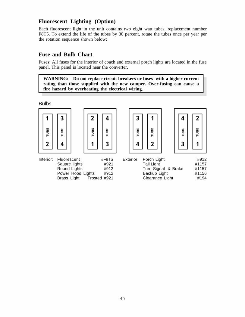
47
Fluorescent Lighting (Option)Each fluorescent light in the unit contains two eight watt tubes, replacement numberF8T5. To extend the life of the tubes by 30 percent, rotate the tubes once per year perthe rotation sequence shown below:
Fuse and Bulb ChartFuses: All fuses for the interior of coach and external porch lights are located in the fusepanel. This panel is located near the converter.
WARNING: Do not replace circuit breakers or fuses with a higher currentrating than those supplied with the new camper. Over-fusing can cause afire hazard by overheating the electrical wiring.
Bulbs
1
2
3
4
TUB
E
TUB
E
2
1
4
3
TUB
E
TUB
E
3
4
1
2TU
BE
TUB
E
4
3
2
1
TUB
E
TUB
E
Interior: Fluorescent #F8TS Exterior: Porch Light #912Square lights #921 Tail Light #1157Round Lights #912 Turn Signal & Brake #1157Power Hood Lights #912 Backup Light #1156Brass Light Frosted #921 Clearance Light #194

48
DC Fuse Panel LayoutPOSITION CIRCUIT NO. FUSE SIZE DESIGNATION6 Positions 1 15 Monitor Panel/Range Hood/Pump(Fig. 4-19) 2 15 Front Bed Lights
3 15 Refrigerator/Furnace4 15 Bath Lights5 15 Entry Lights6 15 TV/Radio/Lights
9 positions 7 15 Main Slideout (1) Lights/Security Lights(Fig. 4-20) 8 20 Reset Main Slideout (1) Motor
9 12.5 Reset Bed Slideout (2) Motor12 Positions 7 15 Main Slideout (1) Lights/Security Lights(Fig. 4-21) 8 15 Dinette Slideout (2) Lights
9 15 Spare10 20 Reset Main Slideout (1) Motor11 Spare +212 12.5 Bed Slideout (3) Motor
Fig. 4-19 Fig. 4-20 Fig. 4-21
BrakesThe electric brakes operate on 12 volt DC power from tow vehicle through blue and whitewires on 7 way pigtail and harness. More information on the brakes is found in Chapter#3.
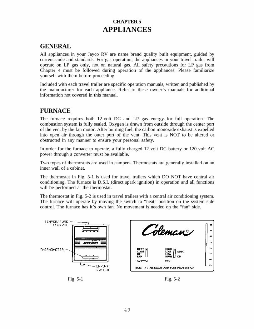
49
CHAPTER 5APPLIANCES
GENERALAll appliances in your Jayco RV are name brand quality built equipment, guided bycurrent code and standards. For gas operation, the appliances in your travel trailer willoperate on LP gas only, not on natural gas. All safety precautions for LP gas fromChapter 4 must be followed during operation of the appliances. Please familiarizeyourself with them before proceeding.
Included with each travel trailer are specific operation manuals, written and published bythe manufacturer for each appliance. Refer to these owner’s manuals for additionalinformation not covered in this manual.
FURNACEThe furnace requires both 12-volt DC and LP gas energy for full operation. Thecombustion system is fully sealed. Oxygen is drawn from outside through the center portof the vent by the fan motor. After burning fuel, the carbon monoxide exhaust is expelledinto open air through the outer port of the vent. This vent is NOT to be altered orobstructed in any manner to ensure your personal safety.
In order for the furnace to operate, a fully charged 12-volt DC battery or 120-volt ACpower through a converter must be available.
Two types of thermostats are used in campers. Thermostats are generally installed on aninner wall of a cabinet.
The thermostat in Fig. 5-1 is used for travel trailers which DO NOT have central airconditioning. The furnace is D.S.I. (direct spark ignition) in operation and all functionswill be performed at the thermostat.
The thermostat in Fig. 5-2 is used in travel trailers with a central air conditioning system.The furnace will operate by moving the switch to “heat” position on the system sidecontrol. The furnace has it’s own fan. No movement is needed on the “fan” side.
Fig. 5-1 Fig. 5-2

50
For Your Safety Read Before Operating
WARNING: If these instructions are not followed precisely, a fire or explo-sion may result causing property damage, personal injury or loss of life.
A. This appliance does not have a pilot light. It is equipped with an ignition device thatautomatically lights the burner. Do not try to light the burner by hand.
B. Prior to operation, smell the area around the appliances to ensure that gas has notsettled on the floor.
C. WHAT TO DO IF YOU SMELL GAS
• Evacuate all persons from the vehicle.• Shut off the gas supply at the gas container or source.• Do not touch any electrical switch or use phone or radio in the vehicle.• Do not start the vehicle’s engine or electric generator.• Contact the nearest gas supplier or qualified service technician for repairs.• If you cannot reach a gas supplier or qualified service technician, contact the
nearest fire department.• Do not turn on the gas supply until the gas leak(s) has been repaired.
D. Use only your hand to turn a gas control valve. Never use tools. If the valve will notturn by hand, do not try to repair it. Call a qualified service technician. Using forcemay result in a fire or explosion.
E. Do not use the appliance if any part has become wet. Immediately call a qualifiedservice technician to inspect and replace any part of the control system and gascontrol which has been under water.
Operating Instructions1. STOP! Read the safety information above.
2. Set the thermostat to lowest setting.
3. Turn off all electric power to the appliance.
4. This appliance is equipped with an ignition device which automatically lights theburner. Do not try to light the burner by hand.
5. Open the control access panel.
6. Turn the valve power switch to “OFF.”
7. Wait five minutes to clear out any gas. Then smell for gas, including near the floor.If you smell gas, STOP! Follow “C” in the safety information. If you do not smellgas, go to the next step.
8. Turn the valve power switch on to the valve.
9. Close the access panel.
10. Turn on all electric power to the appliance.
11. Set the thermostat to desired setting.
12. If the appliance will not operate, follow the instructions TO TURN OFF GAS TOAPPLIANCE (below) and call your service technician or gas supplier.

51
To Turn Off Gas to Appliance1. Set the thermostat to lowest setting.2. Turn off all electric power to the appliance if service is to be performed.3. Open the access panel (Outer Door Assembly) to turn off the electric switch.4. Close the control access panel (Outer Door Assembly).
MaintenanceSee “Furnace Maintenance” in Chapter 7.
Ducting and Return AirAll heat discharges, registers and return air grills must be free and clear of obstructions.Obstructions will prevent the furnace from performing correctly. This includes allclosable registers that are intended to reduce air flow, not shut it off completely.

52
RANGE AND OVEN OPERATION
WARNING: Personal Injury Hazard
• Do not touch or allow clothing and flammable materials to come in contactwith burner grates or areas near top burners until they have sufficient timeto cool. These areas become hot enough to cause burns and fires.
• Ensure that pans used are large enough to contain food and avoid boilovers. Heavy splattering or spills left on the cooktop can ignite and causeburns.
• Ensure that glass cookware is safe for use on the top burners. Only certaintypes of glass cookware is suitable for surface or top burner use.
• Never leave top burners unattended.
• Turn pan handles inward, but not over other top burners. This will reducethe chance of burns.
• Grease is flammable. Never allow grease to collect around top burners or oncooktop surface. Wipe spills up immediately.
• Do not use water on grease fires. Never pick up a flaming pan. Smother aflaming pan with a tight-fitting lid or cookie sheet. Flaming grease outsideof the pan can be extinguished with baking soda or a multipurpose drychemical or foam-type fire extinguisher.
To light the top burners on the range and cooktop models equipped with spark ignition:
a. Turn the appropriate burner knob counterclockwise to “ON” or “LITE/HI.” Do notattempt to light more than one burner at a time.
b. On three burner models, turn the “SPARK” knob clockwise one click. If the burnerfails to light, continue turning the “SPARK” knob clockwise until the burner lights.
c. On four burner models, wait approximately seven seconds after turning the burnerknob to “ON”; press the “SPARK” button once to light the burner. If the burner failsto light, continue pressing the “SPARK” button until the burner lights.
d. To extinguish the top burner flame, turn the appropriate burner knob clockwise to“OFF.”
WARNING: Ensure that stove knobs are pushed all the way onto the stemswhen in the “OFF” position. Failure to do so could result in the stoveinadvertently being turned on. If camping with small children, you may wantto utilize stove knob covers that are available at your local hardware.
WARNING: Burn, Fire and Explosion Hazard
• Use care when lighting a top burner by hand. If the burner lightsunexpectedly, or your hand is close to the burner, you may be burned.
• If any burner should extinguish (after initially lighting or due to accidentalblow-out) turn gas supply off and WAIT FIVE MINUTES before againattempting to light the burner. Failure to follow these instructions mayresult in a fire or explosion.

53
Oven Operation
WARNING: Personal Injury Hazard
• Do not touch or allow clothing or flammable material to come in contactwith the inner or outer surfaces of the oven or the oven vent while it is inuse. These areas all are hot enough to cause burns. Allow sufficient timefor them to cool.
• Do not cover the oven vent openings while the oven is in operation.Restricting the flow of combustion air will create an asphyxiation hazard.
Step 1 – To Light the Oven Pilota. Push in the oven control knob and rotate counterclockwise to “PILOT ON”.b. Light the oven pilot located near the back of the oven, under the broiler shelf and to
the left of the oven burner.c. Set the oven control knob to “PILOT ON” to maintain pilot flame. The oven and
broiler are now ready for operation; see Step 2 before proceeding. The oven pilot hasbeen factory set and requires no further adjustment.
d. To extinguish the oven pilot, push in the oven control knob and rotate clockwise to“OFF.” Extinguish all pilots when refueling or traveling.
Step 2 – To Light the Ovena. Light the oven pilot as described in Step 1.b. With the oven control knob set to “PILOT ON,” rotate the knob counterclockwise
to the desired temperature setting or to “BROIL.”c. The oven is equipped with a safety ignition system that requires a minimum of
thirty seconds to operate after turning the oven control “ON.” This delay is normal.d. To extinguish the oven burner, rotate the knob clockwise to “PILOT ON.” The oven
pilot will remain lit.e. For complete shutdown, rotate the knob clockwise to “OFF.”
WATER HEATERSeveral options are available in the water heater appliances. (1.) 6 or 10 gallon capacities,depending on floor plan. (2.) Three types of energy, LP gas only, LP gas and 120 volt ACcombination, and 12 volt DC /LP gas combination with 110 volt. Water temperature isadjustable on pilot and 120 volt AC models, but not on the combination unit.

54
Pilot Operation
CAUTION: Do not tamper with the pilot orifice. High water temperature andfailure of the gas control could result.
1. Turn lighting control (fig. 5-6B or 5-7B) to “OFF” position.2. Wait at least five minutes to allow gas which may have accumulated in burner
compartment to escape.3. Note that your water heater may have either a “White Rodgers” or Robertshaw
“Unitrol” Control.
FOR “WHITE RODGERS” CONTROL (FIG. 5-6)a. Turn lighting control knob (Fig. 5-6B) to “pilot”
position and hold against stop while lightingpilot burner (Fig. 5-8D)
b. Allow pilot to burn approximately one halfminute before releasing lighting control knob.
c. Turn lighting control knob (Fig. 5-6B) to “ON”position.
d. If pilot does not remain lit, repeat operationallowing longer period before releasing lightingcontrol knob.
e. Set the temperature selection lever (Fig. 5-6A) at the mark between the warmand hot position.
f. Close access door.
FOR A ROBERTSHAW “UNITROL” (FIG. 5-7)a. Turn lighting control dial (Fig. 5-7B) to “pilot”
position.b. Depress and hold reset push button (Fig. 5-7A)
while lighting pilot burner (Fig. 5-8D).c. Allow pilot to burn for one half minute before
releasing reset push button.d. If pilot does not remain lit, repeat operation
allowing longer period before releasing reset pushbutton.
e. Turn lighting control dial (Fig. 5-7B) to “ON” position.f. Set the temperature control dial (Fig. 5-7C) at the midpoint position between
warm and hot.g. Close access door.
4. For complete shut down and before servicing, turn lighting control knob (Fig. 5-6Bor 5-7B) to “OFF” position.
CAUTION: Setting the temperature control dial at a higher position will producewater that is hotter, increasing the risk of scalding.
The temperature knob or lever is factory adjusted to its lowest dial setting. It isrecommended that the midpoint position between warm and hot be used. This willprovide for energy efficient operation and sufficient hot water. Valves for reducing pointof use temperature by mixing cold and hot water are available. Consult a licensed plumberor your local plumbing authority.
Fig. 5-6
Fig. 5-7

55
To adjust Main Burner (Fig. 5-8):
1. Loosen air shutter screw (Fig. 5-8A).
2. Slide air shutter (Fig. 5-8B) to the right until a smallamount of yellow color appears in the main burnerflame.
3. Move air shutter (Fig. 5-8B) to left until yellow disap-pears.
4. Retighten air shutter screw (Fig. 5-8A).
Electric Ignition Operation1. To turn D.S.I. on press rocker switch to the “ON” position. Light will come on
indicating power to board. As soon as burner ignites the light in switch will go off.
2. If remote switch light stays on longer than fifteen seconds, place remote switch inOFF position and wait five minutes.
3. Repeat step one.
4. When water temperature reaches the permanent set thermo-stat, flame shuts down. Reignition will occur when watertemperature drops to 100° automatically.
5. For complete shutdown and before servicing:
a. Place remote switch in “OFF” position.
b. Remove red wire from left hand terminal ofECO switch (ECO to valve).
6. If heater fails to operate due to high watertemperature, the heater will go into a lockout condition (indicator light on). Whenwater cools, reset by placing switch in “OFF” position for at least thirty seconds,then return to “ON” position.
7. If a lockout condition persists contact your dealer, an Atwood service station orAtwood service department.
NOTE: Terminals on switch #2 and 3 supply power to heater. Terminals 4 and 6 supplypower to light. Some models may have switch for D.S.I. water heaters in monitor panel.
Pilot Re-ignite Operation1. Turn the switch located on the spark module to the “ON” position.
2. Read Pilot Operation Instructions.
WARNING: The pilot relight module and thermostat lighting control knobmust both be in the “OFF” position when refueling the LP tank or gasolinetank. Fire and/or explosion could result.
3. For complete shut down, turn lighting control knob on thermostat and spark moduleswitch to the “OFF” position.
Fig. 5-8
Located oninside sidewall
Fig. 5-9

56
Fig. 5-11
Fig. 5-10Electric Operation1. For gas operation refer to Pilot Operation or Electronic
Ignition Operation section.2. For electrical operation, use the switch at the rear of
water heater.3. Completely fill tank with water.4. Turn switch (Fig. 5-10B) located at the rear of the water
heaters to the “ON” position.NOTE: Turning the power on in the heater with little or
no water covering the heating element may burnout the element and void the warranty.
5. Check for proper operation. Water temperature shouldbe approximately 140°F (60°C).
6. If the manual reset high temperature limit switch shouldoperate, reset the switch (Fig. 5-10A) by depressing thebutton. Use a pencil or other nonmetallic object todepress the rest button. If the malfunction repeats,contact an authorized Atwood Service Center or AtwoodService Department.
PRESSURE TEMPERATURE RELIEF VALVE
WARNING: Do not plug the pressure-temperature relief valve under anycircumstances.
When cold water is heated in the tank, the pressure will rise. For this reason, a relief valve(Fig. 5-11) is required for safety in all water heaters rated at 125°. It is normal for thisvalve to release a small quantity of water during the heating cycle. Open the hot waterfaucet to release pressure which will reduce the dripping from the relief valve.
Flushing InstructionsIf your travel trailer is used frequently, or taken to different areas that use various typesof water, it is recommended that the water heater be flushed periodically throughout theyear to prolong the life of the inner tank. The following procedure summarizes the stepsnecessary for flushing the water heater inner tank.
CAUTION: Turn off the water heater and allow time for the water to cool beforeremoving the drain plug to flush the tank.
1. Turn off your main water supply (pump or water hook-up source).2. Drain the water heater inner tank. Approximately two quarts of water will remain in
the bottom of the tank. This water contains a great deal of the harmful corrosivematerial that has accumulated in the tank.
3. Flush tank with air pressure or fresh water to remove the remaining water.Air Pressure: Air pressure may be applied through the inlet or outlet valve locatedon the rear of the tank or the relief valve (Fig. 5-11) located on the front of the unit.If the relief valve is used, remove the relief valve prior to flushing and insert airpressure through the relief valve support flange.

57
Fresh Water: Pump fresh water into tank with the assistance of an onboard orexternal water pressure. The water may also be hosed into the tank through the inletor outlet valve located on the rear of the tank or the relief valve located on the frontof the unit. Continue this process for approximately five minutes, allowing ampletime for the water to agitate the stagnant water on the bottom of the tank and thusforcing any corrosive material through the drain opening.
4. Close the drain and relief valves.
REFRIGERATOR - RV TYPEThis appliance in your Jayco recreation vehicle has been designed by its manufacturer tooperate on 120 volt AC electric or on LP gas energy. Its performance depends onnumerous factors such as energy, venting, leveling, humidity and atmosphere tempera-tures.
LevelingComfortable vehicle leveling is well within the refrigerator’s operating requirements ofthree degrees off level side-to-side and six degrees off level front-to-back (looking at thefront of the refrigerator). Continued operation outside of these limits can result inirreparable damage to the cooling system.
VentingFor the refrigerator to operate correctly there are two vents that must be unrestricted inyour travel trailer. The first vent is located in the lower portion of the sidewall. It is ahinged or removable panel that allows access to service compartments on the refrigerator.The second vent is located in the roof of the travel trailer, above the coils on the rear sideof the refrigerator. Please note, birds might build nests in this vent. It is advisable to retainthe screen over the base to prevent this from occurring.
Door SealTo maintain cooling efficiency and prevent excessive frost buildup, the doors must sealcompletely around the entire length of the door gasket. Frequent frost buildup or reducedcooling are indications of air leaks. To check for complete door sealing, lay a long strip ofpaper or a dollar bill across the flange, against which the gasket seals; then close the door.A frictional drag should be felt when withdrawing the paper. Repeat in several places allaround the door. If the paper feels loose, the gasket is not sealing. Contact your dealer orservice center.
CAUTION: Do not use undue force or jerking action when opening the refrigeratordoor. Air temperature differences can cause a partial vacuum within the cabinetrequiring a firm but steady force to open the door. A sudden jerk could cause doordamage or personal injury.

58
Battery DrainAs indicated, a 12 volt DC source is required for operation on gas to provide features ofautomatic ignition. The drain on the battery is very low and has little effect on “batteryrun down” unless these switches are left on for long periods of time on a battery with nomeans of recharging. The DC voltage should be checked while operating in the DC mode.The voltage at the refrigerator should never drop below 11.5 volts.
Battery drain should also be considered during times when the refrigerator is stored,defrosted, or occasions when the door is left open. The humidity heater, if left on, draws240 milliamps. Because of this small drain, the NORMAL-STORAGE-HIGH HUMIDITYswitch should be set to the STORAGE position.
Except for DC operation (three-way models) it is evident that the 12 volt DC demand isquite low; nevertheless, the refrigerator should not be operated for long periods of timefrom a battery only, without a means of recharging through the alternator or converter.
Controls
CAUTION: Never allow water to be sprayed directly on electrical controls locatedbehind the inlet vent door. Electrical damage or fires could result.
1. Be attentive when the outer surface is being hosed down to avoid wetting therefrigerator controls.
2. The user should be aware that 12-volt DC is required during all operating modes(AC, GAS, DC).
3. This Norcold refrigerator is equipped with electronic ignition (no pilot flame). Itprovides automatic gas ignition on start up, automatic re-ignition in case of flameblowout and electrical signal to warn of flame failure (red X on annuciator panel).
N621 AND N841 SERIES REFRIGERATORSDoor HandlesDuring travel, the door latch prevents the door from opening. When closing the door,push the door toward the refrigerator until you hear a “click” sound. To open the door,pull the handle away from the refrigerator.
During storage, the storage latch prevents the door from completely closing. Use it toprevent odors when the refrigerator is stored for an extended period of time. To operatethe storage latch, open each door about 1/2 inch and push the storage latch into the cutoutof the strike plate. Do not use the storage latch as a travel latch because the doors will notbe fully closed.
Interior LightThe interior light is at the top of the fresh food compartment. It comes on only when therefrigerator is ON and the door is open. To replace the bulb:
1. Remove the DC power supply wires from the power board at the rear of therefrigerator

59
2. Remove the cover. On the model N621, pull the cover toward the front of therefrigerator. On the model N841, push the cover toward the rear of the refrigerator.
3. Remove the light bulb from the holder.
NOTE: Use only a GE#214-2 bulb as the replacement bulb. This bulb is available at mostretail automotive parts centers.
4. Install the replacement bulb.5. Install the cover.6. Connect the DC power supply wires to the power board at the rear of the
refrigerator.
Door AlarmThe refrigerator has an alarm to alert you if the fresh food compartment door is not fullyclosed. The refrigerator continues to operate, but if the fresh food compartment door isopen and the interior light remains on for two minutes:
• An audible alarm starts.• “dr” appears in the center display.• Light turns off.Close the door to silence the alarm.
Backup Operating SystemThis refrigerator has a backup operating system. The backup operating system allows therefrigerator to continue to cool if the temperature sensor of the refrigerator should fail. Ifthis failure occurs, the refrigerator automatically changes to the backup operating system.When you push the TEMP SET button, the temperature setting flashes in the centerdisplay for ten seconds. After the temperature setting flashes, the mode of operationappears in the center display.
NOTE: If you open the door(s) too often, the temperatures inside the freezer and freshfood compartment do not become stable. Allow the refrigerator to operate for about onehour after each adjustment change before to examine the contents. The number “9” is thecoldest temperature setting.
Have the refrigerator serviced by your dealer or an authorized Norcold Service Center assoon as possible.

60
Operating the Refrigerator Controls – N621
CONTROL PANEL
Fig. 5-11
The refrigerator control panel is between the freezer compartment and the fresh foodcompartment.
The ON/OFF button (1) starts and shuts down the refrigerator. If the refrigerator is shutdown, press the ON/OFF button to start the refrigerator in auto mode. If the refrigeratoris operating, press and hold the ON/OFF button for two seconds to shut down therefrigerator.
The TEMP SET button (2) controls the temperature adjustment of the freezer and thefresh food compartment. The temperature adjustment that you select does not change ifthe mode of operation of the refrigerator changes. Press the TEMP SET button and thetemperature setting “1-9” appears in the center display (3). Push and hold the TEMPSET button and the temperature setting changes. The number “9” is the coldest tempera-ture setting.
The MODE button (8) controls the operation mode of the refigerator. Push and hold theMODE button and a light bar flashes in the center display beside each of the fouroperating modes of the refrigerator, one at a time. There is one automatic mode ofoperation, and three manual modes of operation. When the light bar flashes beside themode of operation that you wish, release the MODE button.
AUTOMATIC MODE OPERATIONWhen you select AUTO mode, the refrigerator controls automatically select the mostefficient energy source that is available for operation. If a more efficient energy sourcebecomes available, the refrigerator controls change from the current energy source to themore efficient energy source.
If an energy source is available to the refrigerator, but is not operating correctly: A faultcode appears in the center display. The refrigerator controls try to change to a lessefficient energy source. If a less efficient energy source is not available, the refrigeratorstops operation. Refer to the “Fault Codes” in the manufacturer’s owner’s manual.

61
MANUAL MODE OPERATIONWhen you select one of the manual modes of operation, the light bar beside the AUTOgoes out in the center display and only the light bar beside either AC, LP, or DC remains.AC means that the refrigerator is operating on AC electric. LP means that the refrigeratoris operating on LP gas. If the energy source is interrupted, the refrigerator stopsoperation. Refer to the “Fault Codes” in the manufacturer’s owner’s manual.
IGNITION OF LP GAS IN EITHER AUTO OR MANUAL MODENote: On initial startup of the refrigerator, ignition of the LP gas may not occur within 30seconds.
If ignition of the LP gas does not occur with 30 seconds, the gas safety valve of therefrigerator closes, and the refrigerator stops operation. Refer to the “Fault Codes” in themanufacturer’s owner’s manual. The fault code remains until you push the ON/OFFbutton two times (to stop and start the refrigerator). If ignition does not occur after twoor three times, check the LP gas supply line; consult your local dealer or an authorizedNorcold Serivice Center; change to manual mode and operate on AC electric.
Operating the Refrigerator Controls – N841
CONTROL PANEL
Fig. 5-12
The refrigerator control panel is between the freezer compartment and the fresh foodcompartment. To maintain the operating control functions of the refrigerator, a 12 voltDC power supply is necessary. The refrigerator and any other DC components in thevehicle receive DC power from the 12 volt system of the vehicle; either an auxillarybattery, a converter, or the vehicle engine battery.
The ON/OFF button (1) starts and shuts down the refrigerator. If the refrigerator is shutdown, press the ON/OFF button to start the refrigerator in auto mode. If the refrigeratoris operating, press and hold the ON/OFF button for two seconds to shut down therefrigerator.
The TEMP SET button (3) controls the temperature adjustment of the freezer and thefresh food compartment. The temperature adjustment that you select does not change ifthe operation mode of the refrigerator changes. Press the TEMP SET button and thetemperature setting “1-9” appears in the center display (4). Push and hold the TEMPSET button and the temperature setting changes. The number “9” is the coldest tempera-ture setting.
The MODE button (2) controls the operation mode of the refigerator. Push and hold theMODE button and each of the four operating modes of the refrigerator flash one at a time

62
in the center display. There is one automatic mode of operation, and three manual modesof operation. When the mode of operation that you wish shows in the center display,release the MODE button.
AUTOMATIC MODE OPERATIONWhen you select AUTO mode, the refrigerator controls automatically select the mostefficient energy source that is available for operation. If a more efficient energy sourcebecomes available, the refrigerator controls change from the current energy source to themore efficient energy source.
If an energy source is available to the refrigerator, but is not operating correctly: A faultcode appears in the center display. The refrigerator controls try to change to a lessefficient energy source. If a less efficient energy source is not available, an audible alarmsounds, and the refrigerator stops operation. Refer to the “Fault Codes” in themanufacturer’s owner’s manual.
MANUAL MODE OPERATIONWhen you select one of the three manual modes, “AU” goes out in the center display andeither AC, LP, or DC appears. AC means that the refrigerator is operating on AC electric.LP means that the refrigerator is operating on LP gas. DC means that the refrigerator isoperating on DC electric. If the energy source is interrupted, an audible alarm sounds, andthe refrigerator stops operation. Refer to the “Fault Codes” in the manufacturer’s owner’smanual.
IGNITION OF LP GAS IN EITHER AUTO OR MANUAL MODE
NOTE: On initial startup of the refrigerator, ignition of the LP gas may not occur within30 seconds.
If ignition of the LP gas does not occur with 30 seconds, the gas safety valve of therefrigerator closes.
In the auto mode, the refrigerator control changes to a less efficient energy source (3-waymodels only); the fault code “no” “FL” shows in the center display (2-way models only).
In the manual mode and operating on LP gas, an audible alarm starts, and the fault code“no” “FL” shows in the center display. The audible alarm and the fault code remain untilyou push the MODE button. Push the ON/OFF button two times to stop and start therefrigerator.
If ignition does not occur after two or three times, check the LP gas supply line; consultyour local dealer or an authorized Norcold Serivice Center; change to manual mode andoperate on AC electric, or DC electric (3-way models only).
Ice MakerIce maker is assembled to the refrigerators at the factory as optional equipment. If therefrigerator does not have a factory installed ice maker, one can not be added to therefrigerator at a later time.
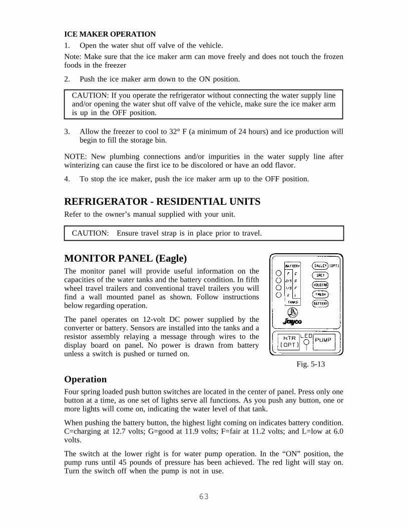
63
ICE MAKER OPERATION1. Open the water shut off valve of the vehicle.Note: Make sure that the ice maker arm can move freely and does not touch the frozenfoods in the freezer
2. Push the ice maker arm down to the ON position.
CAUTION: If you operate the refrigerator without connecting the water supply lineand/or opening the water shut off valve of the vehicle, make sure the ice maker armis up in the OFF position.
3. Allow the freezer to cool to 32° F (a minimum of 24 hours) and ice production willbegin to fill the storage bin.
NOTE: New plumbing connections and/or impurities in the water supply line afterwinterizing can cause the first ice to be discolored or have an odd flavor.
4. To stop the ice maker, push the ice maker arm up to the OFF position.
REFRIGERATOR - RESIDENTIAL UNITSRefer to the owner’s manual supplied with your unit.
CAUTION: Ensure travel strap is in place prior to travel.
MONITOR PANEL (Eagle)The monitor panel will provide useful information on thecapacities of the water tanks and the battery condition. In fifthwheel travel trailers and conventional travel trailers you willfind a wall mounted panel as shown. Follow instructionsbelow regarding operation.
The panel operates on 12-volt DC power supplied by theconverter or battery. Sensors are installed into the tanks and aresistor assembly relaying a message through wires to thedisplay board on panel. No power is drawn from batteryunless a switch is pushed or turned on.
OperationFour spring loaded push button switches are located in the center of panel. Press only onebutton at a time, as one set of lights serve all functions. As you push any button, one ormore lights will come on, indicating the water level of that tank.
When pushing the battery button, the highest light coming on indicates battery condition.C=charging at 12.7 volts; G=good at 11.9 volts; F=fair at 11.2 volts; and L=low at 6.0volts.
The switch at the lower right is for water pump operation. In the “ON” position, thepump runs until 45 pounds of pressure has been achieved. The red light will stay on.Turn the switch off when the pump is not in use.
Fig. 5-13

64
The switch in the lower left corner is for D.S.I. water heater operation if the D.S.I. optionis built into your travel trailer.
Fuses for the monitor panel operation are in 12-volt distribution center fuse block.
Hood Mount (Designer Model Option)1. Press TEST spring loaded button to indicate battery voltage and water level in each
tank.2. Press PUMP button to turn water pump on or off.3. Press FAN button to operate fan hood vent.4. Press LIGHT button to operate the light under the hood vent when cooking.5. Press water heater switch to turn water heater on or off.

65
CHAPTER 6CARE OF BODY COMPONENTS
EXTERIOR ALUMINUMYour new Jayco travel trailer has an improved smooth metal with a new polyesterautomotive paint finish. This metal surface may be cleaned and polished as you wouldyour automobile.
FIBERGLASS SIDEWALLSFiberglass walls are very durable and are easy to maintain. To keep them looking nice,wax and buff them once a year. Standard automotive cleaning soaps and waxes work wellfor general cleaning and maintenance. In addition, do not dry wipe surface. Specialcleaners and waxes are available at automotive and RV stores.
Scratches and chips can be easily fixed by an experienced fiberglass repair shop. Anymajor damage should be repaired as soon as possible to keep cracks from spreading.
EXTERIOR ROOFTwo different types of roof material are used on Jayco campers; rubber EPDM or mill-finished aluminum.
Aluminum - The roof is smooth mill-finished aluminum and needs very little mainte-nance. For washing aluminum material, use a mild detergent soap and water solution.Rinse well after washing. Rinse the sidewalls completely to remove streaking.
Rubber - To keep material looking its best simply wash and clean with a sponge, water,and non-abrasive common household detergent. For stubborn stains use a kitchen cleanserwith bleach. Do not allow the solvent to soak into the rubber material.
CAUTION: All roofs require maintenance. At least once per year, inspect andreseal all seams: front and rear, around all vents, and along all moldings. If you noticeany deterioration in the seal, scrape off any cracked or loose sealant and then resealthe area.
All corners or flat trim have putty tape sealer between the trim and aluminum skin. Thissealant can be damaged by weather elements for cracking and dry-out conditions. Cleanthe edges and cap seal the edge of molding and skin surface, using sealant Extend HD orsimilar. Your dealer can assist you with sealants. This process should be done at leastonce per year.
STONE GUARDWash the stoneguard with liquid dishwashing soap or liquid car washing soap and water.Do not use powdered detergent, powdered soap, liquid and spray cleaners or pressurewashing. Wax frequently to protect the surface and make cleaning easier.

66
ABS PLASTICSABS plastic components such as shower walls, tubs and exterior fenders will retain theiroriginal beauty with reasonable care.
For cleaning:
1. Dust and wipe clean with soft, damp cloth or chamois, wiping gently.2. Wax or polish with Simoniz,® Aero-Wax,® or Glo-Coat® using flannel or jersey cloth.
After polishing, wipe gently with damp cloth to ground electrostatic charges whichmay attract dust particles.
DO NOT use gritty or abrasive particle soaps or scouring compound to clean ABSplastic.
CAUTION: Avoid using “Citrus” or biodegradable cleaners which contain“D-Limonene.” They will damage plastic materials.
FRAMEThe frame of your Jayco recreation vehicle is painted with a water based paint. Roaddebris will chip the paint, inviting rust and other deterioration. Periodically inspect theexterior exposed areas, clean and repaint the steel members in insure a long life. If damagewould occur, the frame needs to be painted with e-coat paint and not a gloss black paint.This type of paint is available in a spray from the vendor, Leland. To prevent rust orcorrosion, you may wish to purchase a commercially available rust treatment application.
DOORS, EXTRUSIONS, WINDOWS & VENTSThese components have putty tape between the component and the wall surface.Portions of these items may have a cap seal added as a secondary seal. Inspect these sealsat least once per year. Both putty tape and cap seals can become damaged by U.V.exposure, air pollution, freezing temperatures and exposure to the elements.
Locks on entrance and baggage doors need biannual lubrication. Silicone lubricant isrecommended. Conditions such as rain, salt, dust and pollution may increase the mainte-nance needs.
FURNITUREFor Cloth Furniture: vacuum occasionally to remove dirt, dust and pet hair. Have steamcleaned when necessary. Test fabric in an inconspicuous location before using any spotcleaners.
For Synthetic Leather: wipe with a soft damp cloth for most dirt and spills, air dry. Ifneeded, use a small amount of a mild liquid detergent. For oil or grease stains, sprayimmediately with an all-purpose spray cleaner or Tannery Car Care Cleaner. Take carenot to smear beyond the original stain. Rinse with clean water, air dry.

67
To Operate Sofa/Recliner Footrest:
1. Make sure cushion is clear of the footrest opening.2. Place heals over the edge of the footrest and pull towards you to release the
safety lock.3. Push down – DO NOT FORCE.
BEDSPREADSDry clean only.
DRAPESMaterials used in bedroom and coach areas consist of different cotton and polyesterblends and should be professionally dry cleaned. Frequent vacuuming is recommended asthe first choice of cleaning.
The shower curtain can be washed on delicate cycle and hung to dry.
WINDOW SHADESMetal venetian blinds may be washed with a mild detergent in warm water or using a softdamp cloth to remove dust. Roller shades may be removed and cleaned using a damp clothor sponge to clean.
CAUTION: To prevent scorching of the window shades, do not use the swivel armlamps located adjacent to the slideout if one of the lampshades is broken or missing.Remove the light bulb and contact a qualified service center for repairs or replace-ment.
PLEATED BLINDS (Designer Only)• Use vacuum cleaner for general dust and lightly soiled material.• Shades are made of polyester material and can be washed with a mild detergent in warm
water.• A mild liquid laundry detergent and warm water may be used for spot cleaning.Tension on strings may be adjusted. If you have difficulty with adjustments, contact yourdealer.
TIRE COVERS - VINYL (Optional)To minimize the possibility of the tire “bleeding” through onto the tire cover, use aseparator (garbage bag, paper cloth, etc.) between the tire and cover.
PANELINGThe wall paneling in your travel trailer is a vinyl covered wood panel. If deep scratchesoccur, putty sticks can be used to cover them. These can be obtained from hardwarestores and lumber yards. For decor paneling, replacement vinyl covering can be purchasedfor repairs if needed. Your dealer’s parts department can assist you with this.

68
To clean, use a mild solution of soap and lukewarm water with a soft sponge or cloth.DO NOT use abrasive cleaners. It could cause the vinyl to scratch and turn dull. Greasespots and stubborn dirt can be cleaned off with an all-purpose spray cleaner. Harshcleaners and organic solvents can attack the printed vinyl and, therefore, are not recom-mended.
VINYL FLOORTo care for the vinyl floor covering, use a damp mop with water and a mild cleaner. DONOT SOAK FLOORING. Use care to avoid wetting carpet edges.
WOOD FLOORUse a cleaner formulated for wood floors.
BATHROOM TUBS, LAVATORY SINKSThe bath tub in your Jayco travel trailer is made of ABS plastic material. DO NOT useabrasive type cleaners, as they may scratch surfaces. Use a mild detergent soap and warmwater to clean the tub surface. These cleaning instructions are similar to those recom-mended for fiberglass tubs and walls. For any type of repair work, see your authorizedJayco dealer.
CARPETINGIf your travel trailer contains carpeting, vacuum frequently. Professional steam cleaningfor tough and deep stains is recommended. Use spot removers for minor spills. ALWAYSTEST CARPET FOR COLOR FASTNESS in an inconspicuous area before using anyproduct.
NOTE: Avoid chemical cleaners. DO NOT permit cleaners to touch carpet or fabrics.
COUNTERTOPSMade of high pressure laminate, the countertops are easy to keep clean. Glass rings, foodspills, water spots and smudges usually wipe off with a damp sponge. Stubborn stainscan be removed with a general purpose spray cleaner. Some stains can be removed bysqueezing fresh lemon juice over the stain and allowing the juice to soak for approxi-mately forty-five minutes. After forty-five minutes, sprinkle baking soda over the lemonjuice and rub with a soft cloth.
HARDWARE AND SINK OR SHOWER FIXTURESUse mild dish soap and water to clean these fixtures. Never use harsh chemicals orsprays. A mild solution of vinegar and water works well to remove hard water spots andstains from the sink or shower fixtures.

69
CHAPTER 7MAINTENANCE/STORAGE
Your new Jayco travel trailer is designed to be as maintenance free as possible. However,maintenance is important to retain its condition as near new as possible. Proper mainte-nance will give you many trouble-free miles.
NOTE: Some areas in this chapter may not be applicable to your coach.
SLIDEOUTYour Power Gear slideout system has been designed to require very little maintenance. Toensure a long life of your slideout system, read and follow these simple instructions.
CAUTION: Do not work on your system unless the battery is disconnected.
• When the slideout is extended, visually inspect the inner slide rail assemblies (Fig. 3-4).Check for excess build-up of dirt or other foreign material; remove any debris that maybe present.
• If the system squeaks or makes any noise, apply a coat of lightweight oil to the driveshaft and roller areas. (Fig. 3-4) Remove excess oil so dirt does not build-up.
• If you have any problems or questions consult your local Jayco dealer or call Power Gear1-800-334-4712.
CARBON MONOXIDE DETECTORTesting
WARNING: DO NOT attempt to test the detector by any other means thanusing the “test” button. DO NOT attempt to produce carbon monoxide totest the detector.
The CO detector should be tested weekly for proper operation:1. Push the test button until the yellow LED lights and a short beep is heard for
approximately three seconds.2. Release button.
The detector will test itself for proper operation. Upon completion of the self-test, thealarm will sound and each of the LEDs will light for approximately ¾ second. Thedetector will then resume normal operation.
Battery ReplacementUnder normal operating conditions, the battery will last approximately one year. Thedetector has a low battery monitor circuit which will cause the detector to make a chirpingsound then the red LED to flash every 30-40 seconds for a minimum of seven (7) daysindicating the battery is low. Replace the battery when this occurs. Use only 9-voltbatteries for the CO detector.
WARNING: Use only the batteries specified for replacement. Use of differ-ent batteries may have a detrimental effect on the CO detector.

70
CleaningUse the following procedure to clean the CO detector:
1. Remove the detector from the mounting plate by rotating the detector in thedirection of the “OFF” arrow on the cover.
2. Clean the interior of the detector by using a vacuum cleaner hose and vacuumingthrough the openings around the perimeter of the detector.
3. Wipe the outside of the detector with a damp cloth.4. Replace the detector back onto the mounting plate.5. Test detector using the testing procedure.
Unit ReplacementThe CO detector should be replaced every six years.
TV ANTENNALubricating the Elevating GearThe elevating gear will need to be lubricated with a liberal amount of silicone spray. Tolubricate, apply the silicone to the elevating gear with the lift in the down position thenrun the lift up and down a few times to distribute the lubricant over the gears.
Lubricating the Bearing SurfaceTwice per year or when rotation of the antenna becomes difficult, lubricate the bearingsurface between the rotating gear housing and the base plate with silicone lubricant spray.Elevate the antenna and remove the set screw or plastic plug from the rotating gearhousing. Spray the silicone into the hole and around the edges of the gear housing. Rotategear housing until the lubricant coats the bearing surface and the antenna rotates freely.
Lubricating the Rubber Quad RingLubricate the rubber quad ring located on the elevating shaft below the worm gear withsilicone spray at least twice per year to prevent the quad ring from becoming brittleresulting in leaks in the elevating shaft. Refer to the vendor’s owner manual for informa-tion regarding removal of the worm gear assembly.
Fig. 7-1 Fig. 7-2 Fig. 7-3

71
FURNACE MAINTENANCEPreventive maintenance and safety checks should be performed by a qualified technicianonce a year, or more, depending on the use of the furnace. Failure to properly maintainthe furnace may void the furnace warranty and can result in unsafe furnaceoperation. Preventive maintenance is NOT covered under the warranty. Powershould be disconnected before servicing.
NOTE: To increase motor life, the furnace should be wired directly to the battery.
TOILETSAqua Magic® Starlite/Galaxy/AuroraNo routine maintenance is required. To clean toilet, use a high grade, non-abrasive RVtoilet bowl cleaner. Do not use highly concentrated or high acid content householdcleaners or scouring powder, as these products can damage seals and finish. Do not useproducts with chlorine or bleach.
Aqua Magic® 4The Aqua Magic® 4 does not require routine maintenance except for cleaning. In someinstallations the seat and cover can be removed to facilitate cleaning. To remove seat, bothseat and cover should be in the open (up) position. Grasp assembly on both sides andpull away from you in an upward angle of approximately 45°. To reinstall seat andcover, place legs of assembly in rear slots of cover until they are centered on hinge postsand gently push down at approximately 45° until you feel the engagement.
STORAGEDepending upon your area and where your unit is stored, your camper may be a target fordamage from rodents and insects. To protect your camper, never leave food inside theunit and ensure that all surfaces are clean. You may want to place rodent control productsin the unit during periods of storage. Mice can do a tremendous amount of damage to thetent, drapes, cushions, etc. particularly during the winter months. Storing units in fieldsmake them particularly inviting to rodents. Periodically inspect your unit during storageand seal off any areas which can offer an entry point to rodents or insects. Pleaseremember to remove any screens or tape you have used to seal openings before you usethe camper again. Special interest publications, such as articles and books offered throughTL Enterprises (Trailer Life, Motorhome, etc.) can offer additional and practical advice onthe proper storage of your camper. Damage from rodents or insects are NOT coveredunder your Jayco Limited Warranty.
CAUTION: When storing your travel trailer, it is recommended that the battery beunhooked to avoid draining the battery.

72
Wheel Bearings The wheel bearings in your newJayco travel trailer are pre-greased. It is recommended thatyou repack these bearings at12,000 miles or at the end ofeach season’s camping to pre-pare for the winter monthsahead.
Use only a multipurpose No. 1or 2 good quality wheel bearinggrease.
If the bearing or cone (race)become pitted, replace anydamaged part.
NOTE: Should you beconcerned about heat in thewheel bearings, check themoccasionally while traveling byplacing your hand on the hub.You will be able to hold yourhand momentarily on the hub.
Should it be extremely hot, it isrecommended to have thebearings inspected by aqualified service center.
NOTE: During the break-inperiod (first 500 miles) yourhubs may feel extra warm dueto brake shoes setting in withthe brake drum.
Exposure to any water or con-densation will cause the bear-ings to rust and be damaged.
Never let the bearings run dry.
Never overpack the wheel bear-ing, especially in the middle ofthe hub. It will trap heat andpossibly disperse grease fromthe seals or dust cap.
MECHANICAL MAINTENANCE CHARTCOMPONENT MAINTENANCE AVOID

73
COMPONENT MAINTENANCE AVOID
Lug Bolts Lug bolts must be checked at 10,25 and 50 miles when your traveltrailer is new or a tire is removedand every 3,000 miles there-after. In addition, the lug boltsshould be checked periodicallyfor safety, especially before longtrips, extensive braking, or tirechanges.
Tighten the lug bolts to 90-120ft. pounds torque using a crosstighten sequence:5 stud = 1-3-5-2-4;6 stud = 1-4-2-5-3-6;8 stud = 1-5-3-7-2-6-4-8.
DO NOT ignore checkingwheel lug bolts.
Coupler Use a small quantity of lubri-cant on the moving mechanismand all points of movement inthe actuator to insure ease ofoperation.
Use conventional grease on thehitch ball for ease of operation.
Fifth Wheel Hitch • Inspect all joints and links fortightness to prevent loss.Design is such that bolts andnuts can be tight and stillfunction properly.
• Lubricate all moving parts offifth wheel for proper opera-tion.
• Grease top surface of wheelto eliminate wear and facili-tate easier turning.
• Before coupling to trailer,inspect all moving parts offifth wheel. Replace all bentor worn parts.
• Thoroughly inspect unit ev-ery 1,000 miles.
• Ensure that all installationbolts and nuts are tight.

74
Change Tire& WheelTo raise coach, place
jack (hydraulic or screw) un-derneath main frame rail, whichspans from front to rear, justinside of tires. Use jack standsor solid-blocking for safe sup-port. Place jack just ahead offront tire or just behind reartire.
You may wish to loosen (only)lug bolts before raising coach.Remove lug bolts after tire clearsground.
COMPONENT MAINTENANCE AVOID
Tongue Jack Lubricate the jack by extendingto full down position and insertSAE 30 oil through oil hole intop of jack. Do this several timesper season.
Fifth WheelLanding Gear
Inspect pad tube and inner ramperiodically.Apply silicone spray to the in-ner tube, pad and inside of handlealignment tube yearly.Grease gears in the gear box andat the top of each leg with ex-treme pressure grease yearly.Oil the shaft bushings with SAE30 oil yearly.Clean electrical connections withbaking soda, then cover with athin coat of grease twice a year.
Excessive quantity of grease.
Excessive oil will run and at-tract dirt.
Tires It is very important to checktires often as noted in Chpt. 3.
DO NOT ignore checking tirepressures often.
Brakes It is important to have brakesadjusted between 200-1,000miles after initial break-in pe-riod by a qualified technician.This operation may or may notbe included as part of sellingprice.
After the initial break-in period,you should adjust the brakesafter each 3,000 miles or at thebeginning of each season’s camp-ing trips.
It is very important to keepbrakes adjusted. Poorly ad-justed brakes will not functioncorrectly. Under adjustmentcan cause an adjuster wheel tofall out.
Never raise the travel trailer byplacing the jack under the axlebeam, springs or any attach-ment parts.

75
COMPONENT MAINTENANCE AVOID
Appliances To care for brushed chrome it isrecommended to clean with amild soap and water. Wipe drywith a soft cloth. Apply a lightcoat of oil such as baby oilperiodically.
Various items on these appli-ances need to be cleaned peri-odically as need be, such asburner orifices, etc. See individ-ual booklets for directions or seeyour dealer.
DO NOT use steel wool, am-monia, acids, or abrasives onchrome surfaces.
Sealants All sealants used in constructionare subject to weather elements.
Tape sealants used arounddoors, windows, extrusions, aresubject to dry-out conditionsby sunlight and water seepage.
Inspect sealants at least twice ayear and look for dried-out,cracking conditions. Reseal atleast once per year.
Using poor quality sealingmaterials. Ignoring sealed areas.
Not resealing once per year.
Entrance Door
Inspect and seal cor-
ners at threshold once a year.
LP Gas System Beginning of each camping trip:1. Inspect all gas lines for
crimps and road damage.2. Check all lines and connec-
tions for leakage with soapywater or leak detector.
3. Have the regulator checkedand adjusted to the properpressure once per year by aqualified dealer.
Roofs All roofs require maintenance.At least twice per year, inspectand reseal all seams: front andrear, around all vents, and alongall moldings. If you notice anydeterioration in the seal, scrapeoff any cracked or loose sealantand then reseal the area.
Not resealing once per year.
DO NOT smoke while chang-ing bottles or any lines.
DO NOT allow connections tobe loose.

76
MAINTENANCE CHECKLIST
Prior to First Trip� Check LP gas lines for leaks.� Test carbon monoxide detector (Generator/Generator Prep option only.)� Test LP gas detector.� Sanitize fresh water system.� Tighten wheel nuts to specified torque values.� Open all windows and the door and start the furnace. Leave the windows and
door open and the furnace on until all fumes fully dissipate.
First Ten Miles� Tighten wheel nuts to specified torque values.
First Twenty-Five Miles� Tighten wheel nuts to specified torque values.
First Fifty Miles� Tighten wheel nuts to specified torque values.
First Two-Hundred Miles� Tighten wheel nuts to specified torque values.� Have brakes adjusted by a qualified service technician.
Each Trip� Test LP gas detector.� Check battery water level. (If equipped with battery.)� Check brake fluid level in master cylinder reservoir. Keep filled to within ½”
from top of reservoir.� Check master cylinder cap for tightness.� Check tire pressure and wear.� Check running lights.� Inspect safety chains for signs of wear.� Test brakes.
After Every Tire Change� Tighten wheel nuts to specified torque values at ten miles, twenty-five miles
and fifty miles.
Daily� Recharge battery after each use.� Ensure LP gas detector operation light is green in color.
Weekly� Test LP gas detector.� Check tire pressure and wear.

77
Monthly� Clean and lubricate the coupler.� Check fire extinguisher pressure. Do not test the extinguisher.� Test the ground fault circuit interrupter (GFCI)
Every Three Months or 3,000 Miles� Vacuum around L.P. Burner and pilot light areas.� Compare water heater pilot flame with ideal flame. Refer to the water heater
owner’s manual for ideal flame. Clean and adjust as necessary.� Compare refrigerator pilot flame with ideal flame. Refer to the refrigerator
owner’s manual for ideal flame. Clean and adjust as necessary. (RV typerefrigerator only)
� Inspect refrigerator door seals.� Inspect refrigerator combustion seals. (RV type refrigerator only)� Check LP gas lines for leaks.� Inspect LP cylinders for rust, pits, gouges, scrapes or sharp dents. Repaint
cylinders if rust is present.� Drain and sanitize fresh water system.� Check, clean, tighten and lubricate battery cables.� Tighten wheel nuts to specified torque values.� Examine the tires for unusual wear, sidewall defects, cuts, wear, bulging and
abrasions.� Lubricate tongue jack.� Lubricate hitch ball.� Have breaks adjusted by a qualified service technician.
Every Four Months or 4,000 Miles� Flush out water heater tanks.
Every Six Months or 6,000 Miles� Clean drains with approved drain cleaners.� Check pipe connections for tightness. Tighten if necessary.� Lubricate all moving parts on the entrance steps.� Lubricate entrance and baggage door locks.� Clean and lubricate stabilizer jacks.� Inspect wheels for cracks, dents or distortion.� Inspect and reseal all sealant and putty tape.� Have suspension system serviced by a qualified service technician.� Lubricate the elevating gear on the television antenna.� Lubricate the bearing surface between the rotating gear housing and the base
plate on the television antenna.� Lubricate the rubber quad ring on the elevating shaft located on the television
antenna.� Clean fifth-wheel landing gear electrical connections with baking soda, then
cover with a thin coat of grease.

78
Every Year or 12,000 Miles� Repack wheel bearings.� Lubricate moving parts on the awning hardware. (Awning option only.)� Oil drive shaft bearings.� Manually operate the pressure-temperature control lever or dial to the lowest
possible position on the water heater.� Clean city water entry strainer.� Check demand tank vent for obstructions.� Check water pump connections and mountings for tightness.� Vacuum the LP gas detector cover.� Rotate Fluorescent tubes in the light fixtures. (XL package only.)� Clean absorption refrigerator flue. (RV type refrigerator only)� Replace battery on the carbon monoxide detector (Generator/Generator Prep
option only.)� Have LP gas system inspected and serviced by a qualified technician.� Inspect and seal corners at the threshold of the entrance door.� Have the refrigerator inspected and serviced by a qualified technician.� Have breaks inspected and serviced by a qualified technician.� Have furnace inspected and serviced by a qualified technician.� Apply silicone spray to the fifth-wheel landing gear inner tube and pad and
the inside of the handle alignment tube.� Grease gears in the gear box and at the top of each leg of the fifth-wheel
landing gear with extreme pressure grease.� Oil the shaft bushings of the fifth-wheel landing gear with SAE 30 oil.
Every Six Years� Replace carbon monoxide detector (Generator/Generator Prep option only.)

79
CHAPTER 8OPTIONS
Note: Each item listed in this chapter is an option as the travel trailer is built by Jayco.
AIR CONDITIONERAir conditioners may be installed by the Jayco factory or by your dealer. If you did notbuy your camper with the optional air conditioner, one of your roof vents may be pre-wired for later installation. Your dealer can provide you with additional informationconcerning this.
There are a variety of air conditioners available. For specific instructions for the airconditioner, consult your dealer and the manufacturer’s owner’s manual.
Some models have Central Air Conditioning available. All cooled air is moved through aduct built into the roof and enters the travel trailer through a group of round registers.
Keep all registers open to insure full airflow. Closing the register(s) may cause thecompressor to freeze, which could shut down the cooling process.
A special foam gasket is placed between the roof material and the subframe of the airconditioner to guard against water leakage.
An air conditioner is subjected to wind pressures along with motor vibration duringnormal operation. Annually inspect the mounting bolts for tightness to ensure there is noleakage or looseness. Retighten bolts when they are loose. DO NOT overtighten thesebolts as it may damage the gasket.
To gain access to the bolts, remove the filtered panel cover on central air systems or theentire air box on non-central air conditioners.
CAUTION: When camping at campgrounds providing less than 30 amp service,discontinue air conditioning use when using the microwave.
GENERATORThe function of a generator is to supply 120 volt AC power on a limited basis whenextended power is not available.
The power to start the generator comes from the auxiliary battery. A start/stop switch islocated on a mounting plate with the generator. A remote start switch may be located onthe monitor panel in the range hood.
With the exception of simple items such as spark plugs and oil changes, all service workshould be done by authorized service centers. Improper adjustments can damage thegenerator and electrical appliances, and can result in a safety hazard. An authorizedservice center has trained specialists who know how to keep your generator runningsafely and reliably.

80
MICROWAVE OVEN / CONVECTION OVENThe microwave oven or convection oven in the unit operate on the same principle as themicrowave/convection in your kitchen at home. A separate owner’s manual is providedwith detailed instructions for its use.
RUBBER ROOFThe heavy-duty rubber roof is durable, does not rumble in the wind, requires no specialtreatment, reduces black streaks on sidewalls, and can be patched if damaged.
To keep your roof looking its best, simply clean it with a sponge and any nonabrasive,common household detergent. For stubborn stains, use a stronger solvent such as xylene,but take care never to saturate.
If your roof is accidently torn or punctured, there’s no need for expensive repairs. Theprocess is much like patching a tire, but we suggest you contact your dealer or Jayco formore information.
As with all trailer roofs, it should be checked at least once a year at roof vents and aroundthe perimeter for signs of cracked or deteriorating sealant. ALPHA 1015 is the best wehave found for roofs. Extend HD works best on horizontal surfaces. Both sealants comein caulking tubes and can be purchased from your Jayco dealer.
RV DIGITAL SATELLITE SYSTEMThe satellite system in the RV is similar to the satellite system in your home. Refer to thedetailed instructions provided by the manufacturer for additional information.
SPARE TIRE CARRIERThe following procedures should be used in securing the spare tire in the travel position:
1. Put the steel hoist lift support located on the end of the cable through the rim of thetire. Clips need to seat inside of the hole.Valve stem of the tire MUST be pointed in the down position or away from thebottom of the travel trailer. Reference Figure 8-1.The hoist will not seat the tire correctly if the valve stem is toward the bottom of thetravel trailer. Reference Figure 8-2.
Figure 8-1 Figure 8-2

81
2. Use the crank handle to lift the tire into the travel position. Two crisp breaks mustbe heard and felt to insure proper seating of the tire for travel.
The tire must be in contact with the surface to be in the travel position.
WARNING: DO NOT exceed the maximum load capacities of 100 lbs. forthe hoist. DO NOT use air driven guns or impact wrenches to lift the tireinto travel position.
CEILING FANFifth-Wheel Travel Trailer Option OnlyThe ceiling fan in the unit operates on the same principle as the fan in your home. Aseparate owner’s manual is provided with detailed instructions for its use.
SECURITY LIGHTSThe security lights can be turned on or off from the entry or bedroom switch.
PATIO DOORThe patio door must be secured during travel with the four travel blocks supplied by themanufacturer.
CAUTION: Ensure travel blocks are installed prior to travel.

82
TOWABLE TRANSFERABLE LIMITED WARRANTY

83
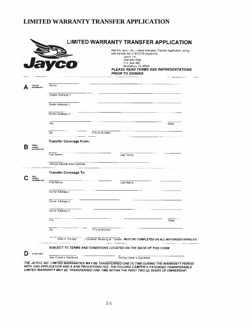
84
LIMITED WARRANTY TRANSFER APPLICATION

85
Terms and RepresentationsBy signing your signature(s) on the face side of this form, and in order toinduce Jayco, Inc. to transfer its Limited Warranty, you represent thefollowing:
1. That you have received and read a copy of the Jayco LimitedWarranty and Owner’s Manual.
2. You understand that the unit is to be used only for recreationalcamping and travel.
3. That all information provided by you on the face side of this form istrue and correct.
4. You understand that you are purchasing a pre-owned recreationvehicle and Jayco, Inc. does not make any representation as to itspresent condition.

®
903 South Main Street • P.O. Box 460 • Middlebury, IN 46540
WELCOME TO THE JAYCO FAMILY!As the owner of a new Jayco recreation vehicle we are proud to
welcome you to our growing family.All Jayco RV homes are built with care, under the watchful eye
of our Quality Assurance program. And it is our sincere wish thatyou will have a lifetime of fun times with your new Jayco.
We are pleased you chose Jayco and want to do everythingpossible to make sure you stay as happy with your Jayco RV homeas you were on the day you bought it.
Jayco dealers are our special partners in customer service;we work closely with them in an effort to keep you satisfied. Wehonestly feel that Jayco dealers are on the whole the best in thebusiness. And with nearly 300 of them in the U.S. and Canada youshould never be too far from help if you ever need it.
In the months and years to come we hope you’llbecome a close member of the Jayco family. Oneway to enjoy your Jayco even more is through ourowners club – the Jafari International Travel Club.It’s lots of fun and a great way to meet othermembers of the Jayco family. If you’re interestedplease talk to your dealer about the “flight” in yourarea. Or write to us directly and we’ll be in touch.
From Jayco’s family to yours: “Welcome Home!”