Embed Size (px)
Citation preview

W H E N Q U A L I T Y I S A N I S S U E , T H E C H O I C E I S H A E F E LY
H IGH VOLTAGECONSTRUCTION KIT
H I G H V O L T A G E T E S T
KIT

HIGH VOLTAGE CONSTRUCTION KIT
APPL ICATION
2
The High Voltage Construction KIT is a system ofcomponents for applications in high voltage technology. All components have the same lengthand mechanical interconnections. They can becombined to form a test configuration and areextremely versatile. Test configurations are availablewhich allow the generation of AC voltages up to300 kV, DC voltages up to 400 kV and impulsevoltages up to 400 kV with different output powerratings.Such test configurations are extremely compact andtheir flexibility allows the test system to be matchedto the prevailing conditions in the test room(dimensions, height etc.).The application range for the high voltage KITcovers not only use in high voltage laboratories oftechnical universities, but also as an industrial testsystem for routine and type tests on electricalequipment up to 30 kV.
KIT
A complete test system requires a volume of 30 m3
and a floor surface of three by four meters.
The configuration is built up, as it name suggests,by simply inserting the various elements to form aself-supporting structure. No tools are required.In spite of its striking simplicity, the KIT is equippedwith all the components of comparable large indu-strial test systems. The accuracy of the measuring instruments is suchthat they compare favourably with larger test systemsand are used by calibration laboratories.Numerous accessories are available for the basic KITelements. The high voltage KIT has very compactdimensions and a wide range of application. It isportable and truly represents a complete high voltagetest system.
3rd stage
2nd stage
1st stage
AC DC IMP

GENERAL SPECIF ICATION
3
Design of the high voltage KIT follows nine majorfactors. These are:• A clear structure is required to ensure that the
assembled circuits can be easily checked both bystudents and theirs instructors.
• Rapid set up of the circuit in order to have asmuch time for active experiments as possible. The assembly of a circuit should not take longerthan the connection of a previously equippedhigh voltage test system.
• As few elements as possible should be used in order to maintain the simplicity of the system andreduce replacement parts. A minimum of hardwarealso makes sound economic sense.
• Lightest possible weight of the individual compo-nents. This allows circuits to be built up by oneperson only, without danger.
• All components can be used in all possible circuitsfrom the mechanical, thermal and electrical pointof view.
• Design for low Corona-effects Special attention must be paid to this require-ment due to the ever increasing demand placedon modern high voltage equipment to achievethe lowest possible partial discharge level.
• As few oil-filled components as possible should beused. A leak-proof construction for the oil-filledcomponents is required.
• Highest reliability.Potential rough handling of the components during experimentation means that the compo-nents should be virtually maintenance free. Therecommended constructions should be extremelysimple.
• KIT should look good!
Various elements joined together by a connection cup

GENERAL REMARKS FOR SETUP
4
KIT
The assembly of high voltage circuits using the highvoltage construction KIT is quick and easy.
An example is the structure of an AC circuit 100 kV(without matching transformer or control unit).
The configuration is built up by inserting elementsto form a self-supporting arrangement. No additionaltools are required.Thanks of this simple, but sophisticated design theuser can make changes in the circuit quickly andefficiently. That’s especialy an advantage, for com-bined systems. Every connection cup has six possiblecombinations. Two vertical and four horizontal.
Every floor pedestal has two threads on oppositesides for ground connection. This way the groundingcan be made at the end of the assembly simply byscrewing the copper foil to the floor pedestalswithout need to rearrange them.
Configurations with more than just one stage canbe build as in the following examples.
PZT 100-0.1
PZT 100-0.1 Spacer Bar
Floor Pedestal
Connection Rod
KIT Element
Connection Cup
Insulating Support
Mul t i s tage Conf igurat ion, extens ion or ra i se
Transformers Other elements
Connection rod
Test Transformer
Connection Cup
Measuring Capacitor
Floor Pedestal

BASIC CONFIGURATION
Type Description AC DC IMP voltage voltage voltage
Stages 1 2 3 1 2 3 1 2 3
PZT 100-0.1 Test Transformer 100 kV, 10 kVA 1 2 3 1 1 1 1 1 1
KDL 1) Compensating Reactor 2 3
Top EL Top Electrode for PZT 100-0.1 1 1
STL 2) Regulating Transformer 1 1 1 1 1 1 1 1 1
OT 276 Control Unit 1 1 1 1 1 1 1 1 1
DMI 551 Digital Measuring Instrument 1 1 1 1 1 1 1 1 1
HSV 200 High Voltage Connection 1
HSV 300 High Voltage Connection 1
GS HV Rectifier 2 4 6 2 2 2
RE 2.5 Discharge Resistor, 2.5 kΩ 1 1 1 1 1 1
CS Smoothing Capacitor 1 3 5 1 2 3
CB Load Capacitor 1 2 3
RL Charging Resistor 1 2
RD Wave Front Resistor 1 2 3
RE Wave Tail Resistor 1 2 3
CM Measuring Capacitor 1 2 3 1 1 1
RM Measuring Resistor 1 2 3 1 1 1
ES Grounding Switch 1 1 1 1 1 1
EST Discharge Rod 1 1 1 1 1 1 1 1 1
EL Top Electrode 1 1 2 7 5 2 2 2
IS Insulating Support 2 9 12 2 5 12
KF Sphere Gap 1 2 3
AKF Drive for Sphere Gap 1 1 1
V Connection Rod 1 1 3 3 1 4 6
K Connection Cup 1 2 3 4 11 14 6 13 21
F(s) Floor Pedestal 1 1 1 4 6 7 6 8 8
D Spacer Bar 2 5 7 4 7 8
NTZ Secondary Part for CB (Impulse) 1 1 1
SEK AC Secondary Part for CM (AC) 1 1 1 1 1 1 1 1 1
SEK DC Secondary Part for RM (DC) 1 1 1 1 1 1
MK BNC Coaxial Measuring Cable 1 1 1 1 1 1 1 1 1
DMI ZAG Triggering Device 1 1 1
EZK Electronic Trigger Sphere, incl. cable 1 1 1
5
1) For AC voltage test system with more than 1 stage compensating reactors are highly recommended.2) STL 5 (5 kVA) is standard. For test objects with higher capacitive load regulating transformers with 7.5 kVA or 10 kVA are also available.

AC - VOLTAGE
AC - S INGLE STAGE
6
without compensating reactor1h ON, 1h OFF
continuous 4 x day Regulating transformer STL 5 STL 7.5 STL 10 STL 10Rated voltage [kV rms] 100 100 100 100Base load (CM) [pF] 100 100 100 100
Frequency [Hz] 50 50 50 50Rated current [mA] 50 75 90 100Output [kVA] 5 7.5 9 10Impedance voltage (approx.) [%] 2.6 3.9 4.6 -Max. capacitive load, Cload [nF] 1.4 2.3 2.7 3.1
Frequency [Hz] 60 60 60 60Rated current [mA] 50 75 90 100Output [kVA] 5 7.5 9 10Impedance voltage (approx.) [%] 3.1 4.7 5.6 -Max. capacitive load, Cload [nF] 1.2 1.9 2.3 2.5
remark: Impedance voltage relates to rated power continuous and rated frequency.Technical data is subject to alterations.
KIT
PZTCM
F(s)
KV

7
AC - TWO STAGES
without compensating reactorcontinuous
Regulating transformer STL 5 STL 7.5 STL 10Rated voltage [kV rms] 200 200 200Base load (2 x CM) [pF] 50 50 50
Frequency [Hz] 50 50 50Rated current [mA] 15 30 38Output [kVA] 3 6 7.6Impedance voltage (approx.) [%] 4 7 8Max. capacitive load, Cload [pF] 180 420 550
Frequency [Hz] 60 60 60Rated current [mA] 15 28 36Output [kVA] 3 5.6 7.2Impedance voltage (approx.) [%] 5 8 10Max. capacitive load, Cload [pF] 150 320 420
with compensating reactorcontinuous 1h ON, 1h OFF, 4 x day
Regulating transformer STL 5 STL 7.5 STL 10 STL 7.5 STL 10Rated voltage [kV rms] 200 200 200 200 200Base load (2 x CM) [pF] 50 50 50 50 50
Frequency [Hz] 50 50 50 50 50Rated current [mA] 39 75 80 95 100Output [kVA] 7.8 15 16 19 20Max. capacitive load, Cload [nF] 0.57 1.15 1.2 1.45 1.55
Frequency [Hz] 60 60 60 60 60Rated current [mA] 36 65 80 85 100Output [kVA] 7.2 13 16 17 20Max. capacitive load, Cload [nF] 0.4 0.75 0.95 1.05 1.25
HSEV 200
PZT
K
CM
F(s)

AC - THREE STAGES
8
without compensating reactorcontinuous
Regulating transformer STL 7.5 STL 10Rated voltage [kV rms] 300 300Base load (3 x CM) [pF] 33 33
Frequency [Hz] 50 50Rated current [mA] 10 10Output [kVA] 3 3Impedance voltage (approx.) [%] 8 9Max. capacitive load, Cload [pF] 70 70
Frequency [Hz] 60 60Rated current [mA] 5 5Output [kVA] 1.5 1.5Impedance voltage (approx.) [%] 8 9Max. capacitive load, Cload [pF] 10 10
KIT
AC - VOLTAGE
HSEV 300
PZT
K
CM
F(s)
with compensating reactorcontinuous 1h ON, 1h OFF, 4 x day
Regulating transformer STL 5 STL 7.5 STL 10 STL 10Rated voltage [kV rms] 300 300 300 300Base load (3 x CM) [pF] 33 33 33 33
Frequency [Hz] 50 50 50Rated current [mA] 20 60 80Output [kVA] 6 18 24Max. capacitive load, Cload [pF] 175 595 815
Frequency [Hz] 60 60 60 60Rated current [mA] 17 50 60 80Output [kVA] 5.1 15 18 24Max. capacitive load, Cload [nF] 115 405 495 675

9
continuousRegulating transformer STL 5Smoothing capacitor CS 25 nF 50 nF (2 x 25 nF)Rated no-load voltage [kV] 140 140Rated output [kVA] 5 5Rated current [mA] 11.2 21.5Ripple [%] 3 3Voltage drop at rated current [kV] 20 30
Rated current is limited by the ripple of 3% according IEC 600060-1.Technical data is subject to alterations
DC - VOLTAGE
PZT
GS VK
IS CS ES
RM
F(s)
DC - S INGLE STAGE
Load CharcteristicKITDC 1-stage
0
50
100
150
200
250
300
350
400
0 5 10 15 20 25
OutputCurrent[mA]
OutputVoltage
[kV];Ripple[%x100]
Load diagram for KIT DC single stage (CS = 50 nF = 2x25 nF)Load diagram for KIT DC single stage (CS = 25 nF)

10
KIT
continuousRegulating transformer STL 5Smoothing capacitor CS 25 nF 50 nF (2//25)Rated no-load voltage [kV] 280 280Rated output [kVA] 5 5Rated current [mA] 11.0 21,5Ripple [%] 3 3Voltage drop at rated current [kV] 40 60
Rated current is limited by the ripple of 3% according IEC 600060-1.Technical data is subject to alterations
PZT
GS K
RM
F(s)ESD
CSV
IS
DC - TWO STAGES
Load diagram for KIT DC two stages (CS = 25 nF) Load diagram for KIT DC two stages (CS = 50 nF = 2x25 nF)

DC - THREE STAGES
11
continuousRegulating transformer STL 5Smoothing capacitor CS 25 nF 50 nF (2//25)Rated no-load voltage [kV] 400 400Rated output [kVA] 5 5Rated current [mA] 8,2 17Ripple [%] 3 3Voltage drop at rated current [kV] 30 60
Rated current is limited by the ripple of 3% according IEC 600060-1.Technical data is subject to alterations
GSCS
ES
PZT
V
ISF(s)
D
Load diagram for KIT DC three stages (CS = 50 nF = 2x25nF)Load diagram for KIT DC three stages (CS = 25 nF)

12
KIT
IMP - Single StageImpulse Capacitance
25 nF (1 x CS25) 50 nF (2 x CS25)Max. total charging voltage [kV] 140 140Max. energy at max. charging voltage [J] 250 490Max. output voltage LI no load [kV] 125 130Max. output voltage LI max. load [kV] 98 115Max. capacitive load for LI [pF] 7000 5800Max. output voltage SI no load [kV] 118 123Max. output voltage SI max. load [kV] 99 112Max. capacitive load for SI [pF] 5000 4500
S INGLE STAGE
IMPULSE VOLTAGE
Basic configuration per stage: LI (IEC 60-1) SI (IEC 60-1)Smoothing capacitor, CS [nF] 25 50 25 50Load capacitor, CB (divider) [nF] 1.2 1.2 1.2 1.2Wave tail resistor, RE [kΩ] 2.4 2.4//2.4 120 120//120
Wave front resistor RDA [Ω] 355 355 55000 55000Load range with RDA, Cload [pF] 0...400 0...400 0...300 0...290Output voltage at min. load with RDA [kV] 125 130 118 123Output voltage at max. load with RDA [kV] 122 127 115 120
Wave front resistor RDB [Ω] 220 220 35000 35000Load range with RDB, Cload [pF] 250...1600 250...1500 220...1200 220...1150Output voltage at min. load with RDB [kV] 124 130 119 124Output voltage at max. load with RDB [kV] 116 125 112 119
Wave front resistor RDC [Ω] 140 140 22000 22000Load range with RDC, Cload [pF] 1300...3700 1200...3200 1100...2800 1100...2600Output voltage at min. load with RDC [kV] 120 128 115 122Output voltage at max. load with RDC [kV] 108 120 106 116
Wave front resistor RDD [Ω] 95 95 15000 15000Load range with RDD, Cload [pF] 3000...7000 2700-5800 2300...5000 2200...4500Output voltage at min. load with RDD [kV] 112 124 111 120Output voltage at max. load with RDD [kV] 98 115 99 112
Load Range
The best suitable wave front resistor can be chosen according to the expected load. One resistor is included in the basic configuration butcan be selected. Technical data is subject to alterations

13
Load range for switching impulse single stage (CS = 25 nF) Load range for switching impulse single stage (CS = 50 nF = 2x25 nF)
Load range for lightning impulse single stage (CS = 25 nF) Load range for lightning impulse single stage (CS = 50 nF = 2x25 nF)
PTZ
GS
DIS CS
RD
CB
ES
KFRE
DD

KIT
14
TWO STAGES
IMPULSE VOLTAGE
Impulse Capacitance25 nF (1 x CS25) 50 nF (2xCS 25)
Max. total charging voltage [kV] 280 280Max. energy at max. charging voltage [J] 490 960Max. output voltage LI no load [kV] 243 258Max. output voltage LI max. load [kV] 196 233Max. capacitive load for LI [pF] 2500 2600Max. output voltage SI no load [kV] 229 244Max. output voltage SI max. load [kV] 198 223Max. capacitive load for SI [pF] 3500 2300
Basic configuration per stage: LI (IEC 60-1) SI (IEC 60-1)Smoothing capacitor, CS [nF] 25 50 25 50Load capacitor, CB (divider) [nF] 1.2 1.2 1.2 1.2Charging resistor, RL [MΩ] 2.5 2.5 2.5 2.5Wave tail resistor, RE [kΩ] 2.4 2.4//2.4 120 120//120Wave front resistor RDA [Ω] 355 355 55000 55000Load range with RDA, Cload [pF] 0...200 0...200 0...150 0...150Output voltage at min. load with RDA [kV] 249 258 234 244Output voltage at max. load with RDA [kV] 243 255 229 239
Wave front resistor RDB [Ω] 220 220 35000 35000Load range with RDB, Cload [pF] 150...800 100...720 120...600 120...580Output voltage at min. load with RDB [kV] 248 260 237 247Output voltage at max. load with RDB [kV] 233 250 222 236
Wave front resistor RDC [W] 140 140 22000 22000Load range with RDC, Cload [pF] 650...1800 460...1450 550...1400 530...1300Output voltage at min. load with RDC [kV] 239 256 230 244Output voltage at max. load with RDC [kV] 218 243 212 230
Wave front resistor RDD [Ω] 95 95 15000 15000Load range with RDD, Cload [pF] 1500...3500 1000...2600 1200...2500 1100...2300Output voltage at min. load with RDD [kV] 225 251 220 240Output voltage at max. load with RDD [kV] 196 233 198 223
Load Range
The best suitable wave front resistor can be chosen according to the expected load. One resistor is included in the basic configuration butcan be selected. Technical data is subject to alterations

Load range for switching impulse two stages (CS = 25 nF) Load range for switching impulse two stages (CS = 50 nF = 2x25 nF)
Load range for lightning impulse two stages (CS = 25 nF) Load range for lightning impulse two stages (CS = 50 nF = 2x25 nF)
15
RD
CS
KF RD
RECB
RE
KF
CS
V
F(S)ES
GS
PZT

KIT
16
THREE STAGES
IMPULSE VOLTAGE
IMP - Three StagesImpulse Capacitance
25 nF (1 x CS25) 50 nF (2xCS25)Max. total charging voltage [kV] 420 420Max. energy at max. charging voltage [J] 740 1440Max. output voltage LI no load [kV] 365 388Max. output voltage LI max. load [kV] 295 348Max. capacitive load for LI [pF] 2300 1900Max. output voltage SI no load [kV] 341 364Max. output voltage SI max. load [kV] 295 335Max. capacitive load for SI [pF] 1700 1500
Basic configuration per stage: LI (IEC 60-1) SI (IEC 60-1)Smoothing capacitor, CS [nF] 25 50 25 50Load capacitor, CB (divider) [nF] 1.2 1.2 1.2 1.2Charging resistor, RL [MΩ] 2.5 2.5 2.5 2.5Wave tail resistor, RE [kΩ] 2.4 2.4//2.4 120 120//120
Wave front resistor RDA [W] 355 355 55000 55000Load range with RDA, Cload [pF] 0...130 0...130 0...100 0...100Output voltage at min. load with RDA [kV] 373 388 350 364Output voltage at max. load with RDA [kV] 365 382 341 357
Wave front resistor RDB [Ω] 220 220 35000 35000Load range with RDB, Cload [pF] 80...500 80...480 70...400 70...400Output voltage at min. load with RDB [kV] 373 390 355 370Output voltage at max. load with RDB [kV] 350 375 332 352
Wave front resistor RDC [Ω] 140 140 22000 22000Load range with RDC, Cload [pF] 430...1200 400...1050 360...950 360...880Output voltage at min. load with RDC [kV] 359 382 345 366Output voltage at max. load with RDC [kV] 326 363 316 345
Wave front resistor RDD [Ω] 95 95 15000 15000Load range with RDD, Cload [pF] 1000...2300 900...1900 750...1700 730...1500Output voltage at min. load with RDD [kV] 338 372 333 360Output voltage at max. load with RDD [kV] 295 348 295 335
Load Range
The best suitable wave front resistor can be chosen according to the expected load. One resistor is included in the basic configuration but can be selected. Technical data is subject to alterations

Load range for switching impulse three stages (CS = 25 nF) Load range for switching impulse three stages (CS = 50 nF =2x25 nF)
Load range for lightning impulse three stages (CS = 25 nF) Load range for lightning impulse three stages (CS = 50 nF =2x25 nF)
17
RD
CS
RD RE
RE
CB
V
ES
GS
KF
RE
RL
PZT
IS
RD
RL

KIT
18
The high voltage KIT is supplied with two separateinstruments: The OT 276 control unit and the DMI 551 AC, DCand impulse measurement unit. Both instruments are available as desktop or rackversions.
OT 276 controls the regulating transformer. It isbased on conventional relay technology and isbuilt into a 19" standard housing of 3 units.Operation is by means of push buttons. The stateof contactors as well as the current and voltage onthe secondary side of the regulating transformerare clearly indicated on the front plate by meansof LED displays.The OT 276 is equipped with required safety functions by laboratories large test and also thoserequired by the standards.
With the KIT it is often required to measure AC,DC and impulse voltages at the same time.Therefore the DMI 551 is equipped with threeindependent measuring channels (AC, DC, IMP)and can display all three values simultaneously.The DMI 551 is a microprocessor controlled instru-ment. Input is via the numeric keypad. A largeLCD-Display indicates measured values and thefunction options.With its optional triggering function, firing of theimpulse configuration or a chopping gap is possible.An interface (RS-232 or IEEE-488) is also availablefor connection to a host computer.The DMI 551 is designed in accordance with theinternational standard IEC 60.
CONTROL AND MEASURING
OT 276
DMI 551

COMPONENTS
PZT 100-0.1 Single phase AC voltage test transformer
Test transformer which can be used for AC-, DC- and impulse voltage gene-ration. The output power can be extended by cascading the transformers.
Ratio: 2 x 220 V / 100 kV / 220 VCurrent cont.: 2 x 20 A / 90 mA / 20 ACurrent 1 h: 2 x 22 A / 100 mA / 22 AOutput power: 9 kVA continuous,
10 kVA 1h ON, 1h OFF, 4 x per dayImpedance voltage: approx. 5%Frequency: 50/60 HzPartial discharge level: ≤ 2 pCWeight: 290 kg
KDL Compensating reactor
Compensating reactor type KDL are used between transformers (PZT 100-0.1)in cascade circuits to reduce input power and provide uniform voltage distri-bution across cascade winding. Compensating reactors are recommended forAC configurations of more than 1 stage.
Top EL Top electrode
For AC two and three stages a top electrode on the test transformer isrecommended to provide corona effects.
Diameter: 820 mmRing diameter: 220 mmWeight: 9 kg
STL 5, (STL 7.5, STL 10) Regulating transformer
Power supply: 230 V / 22 A (33, 43 A)Secondary voltage: 0 ... 230 VRated power: 5 kVA (7.5, 10 kVA) cont.Frequency: 50/60 HzWeight: 80 kg (255 kg, 260 kg)
19
HSEV 200 HV Connection 200 kV
Flexible connection with suitable contacts to connect a two stage AC voltageconfiguration to the test transformer.
Length: approx. 1 m
HSEV 300 HV Connection 300 kV
Flexible connection with suitable contacts to connect a three stage AC volta-ge configuration to the test transformer.
Length: approx. 2 m
GS HV rectifier
Rectifier, which can be used for impulse and DC voltage configurations.
Built-in protective resistor: 100 kΩInverse peak voltage: 140 kVRated current: 20 mAWeight 9.1 kg
RE Parallel (Wave tail) resistor
Resistor, which can be used as discharge resistor for DC and impulse voltageconfigurations and as parallel resistor in impulse voltage configurations,determining the duration.
Resistance: different values (2.4, 2.5, 120 kΩ)Max. DC and IMP voltage: 140 kVWeight: 4 kg
CS 25 Smoothing capacitor
Capacitor, which can be used as energy storage capacitor for generation ofimpulse voltages or as smoothing capacitor for DC generation.
Capacitance: 25 nFMax. DC and IMP voltage: 140 kVWeight: 15 kg
CB Load capacitor
Capacitor, which can be used as HV unit for measuring of impulse voltagesand as load capacitance.
Capacitance: 1200 pFMax. DC and IMP voltage: 140 kVWeight: 9.5 kg
KIT
20
COMPONENTS

RL Charging resistor
Resistor, which can be used as charging resistor for multistage impulse confi-gurations, as current limiting resistor in DC configurations and as dampingresistor in connection with the grounding switch.
Resistance: 10 MΩ or 2.5 MΩMax. DC and IMP voltage: 140 kVWeight: 4.5 kg
RD Series (Wave front) resistor
Resistor, which can be used as series resistor for impulse voltage configurati-ons, determining the wave risetime.
Resistance: different values (95, 140, 220, 355 Ω, 15, 22, 35, 55 kΩ
Max. DC and IMP voltage: 140 kVWeight: 4.5 kg
CM Measuring capacitor
Capacitor, which can be used as HV unit for measuring of AC voltages.
Capacitance: 100 pFMax. AC voltage: 100 kVWeight: 10 kg
RM Measuring resistor
Resistor, which can be used as HV unit for measuring of DC voltages.
Resistance: 280 MΩRated current (continuous): 0.5 mAMax. DC voltage: 140 kVWeight: 4 kg
ES Grounding switch
Remote controlled switch, which can be used to ground the high voltageconstruction KIT.
Max. DC and IMP voltage: 140 kVService voltage: 24 V, 50/60 HzWeight: 6.5 kg
EST Discharge rod
Rod, for manual discharge of HV KIT components.
Length: 2.5 mDischarge resistance: 100 WWeight: 1.5 kg
21

EB Ground foil
Copper ground foil, which can be used to make ground connections bet-ween the individual high-voltage apparatus.
Copper foilWeight: 0.44 kg/m
EL Electrode
Electrode, used together with grounding switch ES and for termination topelements when test set should be corona-free.
Diameter: 300 mmWeight: 2 kg
IS Insulating support
Support insulator, which can be used as insulating component.
Max. AC voltage: 100 kVMax. DC and IMP voltage: 140 kVWeight 1.5 kg
KF Sphere gap
Sphere gap, for impulse voltage configuration.
Max. IMP voltage: 140 kVSphere diameter: 100 mmMax. gap setting: 80 mmWeight: 6 kg
AKF Drive for sphere gap
Remote controlled drive for sphere gap KF and MF100. Drive shaft ASA(short) for 1st Stage and ASB (long) for 2nd and 3rd Stage needed. The AKFis clamped to a spacer bar D.
With capacitor motor: 230 VFrequency: 50/60 HzWeight: 6 kg
KIT
22
COMPONENTS
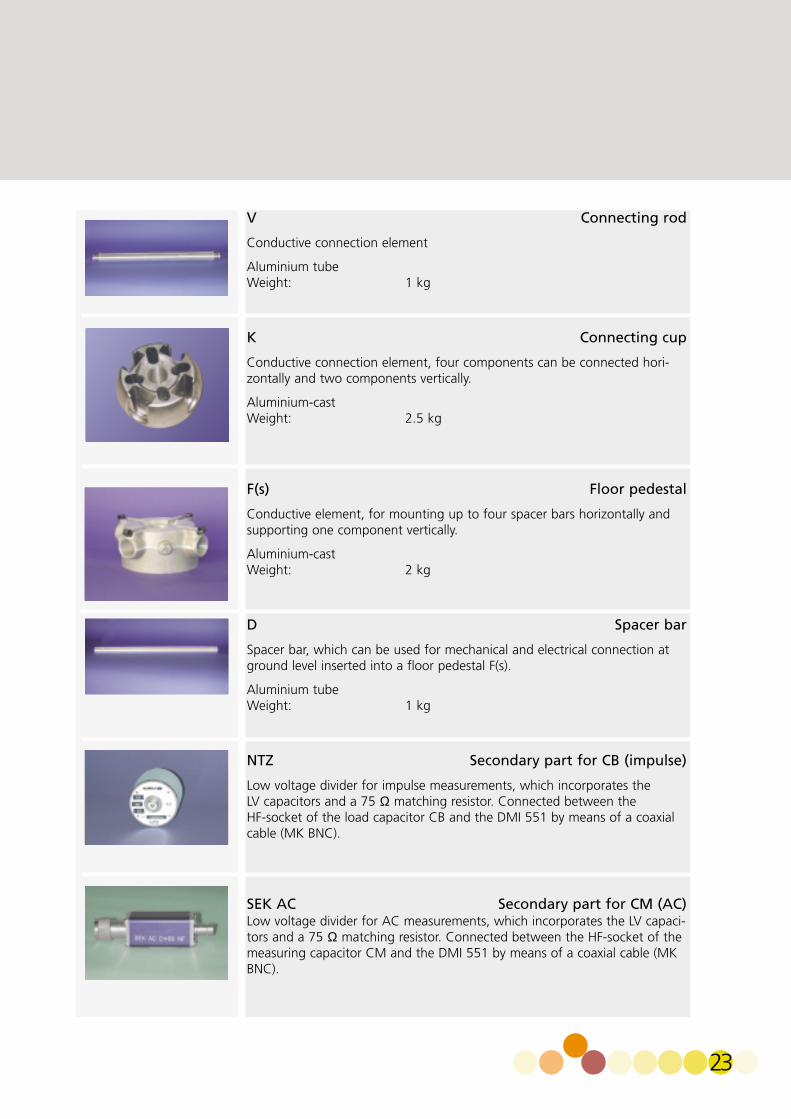
V Connecting rod
Conductive connection element
Aluminium tubeWeight: 1 kg
K Connecting cup
Conductive connection element, four components can be connected hori-zontally and two components vertically.
Aluminium-castWeight: 2.5 kg
F(s) Floor pedestal
Conductive element, for mounting up to four spacer bars horizontally andsupporting one component vertically.
Aluminium-castWeight: 2 kg
D Spacer bar
Spacer bar, which can be used for mechanical and electrical connection atground level inserted into a floor pedestal F(s).
Aluminium tubeWeight: 1 kg
NTZ Secondary part for CB (impulse)
Low voltage divider for impulse measurements, which incorporates the LV capacitors and a 75 Ω matching resistor. Connected between the HF-socket of the load capacitor CB and the DMI 551 by means of a coaxialcable (MK BNC).
SEK AC Secondary part for CM (AC)Low voltage divider for AC measurements, which incorporates the LV capaci-tors and a 75 Ω matching resistor. Connected between the HF-socket of themeasuring capacitor CM and the DMI 551 by means of a coaxial cable (MKBNC).
23

COMPONENTSK
IT
24
SEK DC Secondary part for RM (DC)
Low voltage divider for DC measurements, which incorporates the LV resistors and a 75 Ω matching resistor. Connected between the HF-socket of the measuring resistor RM and the DMI 551 by means of a coaxial cable(MK BNC)
MK BNC Coaxial measuring cable
Coaxial cable with BNC plugs can be used to connect high-voltage dividersto measuring instruments (DMI 551).
Impedance: 75 ΩStandard Length: 10 mother lengths on request
EZK Electronic trigger sphere
Trigger sphere, which is used to generate triggered impulses in impulse volta-ge configurations together with sphere gap KF and triggering device DMIZAG. Chopped impulses can be generated with an additional EZK togetherwith the measuring spark gap MF 100. Supplied with fibre-optics cable LWL.
Diameter: 100 mmWeight: 0.7 kgStandard length of cable: 10 m
DKU Vessel for vacuum and pressureVessel, which can be used to determine flashover voltage of electrode arran-gements as a function of vacuum and over pressure.
Max. AC voltage: 100 kVMax. DC and IMP voltage: 140 kVMax. operating pressure (abs.): 0 - 6 barWeight: 12 kg
DKU ZUB Additional set of electrodes Additional electrodes for use with the DKU.
Sphere electrodes dia. 50 mmSphere electrodes dia. 20 mmNeedles electrodes

25
D(D) Spacer bar
Spacer bar, which can be used to connect a floor pedestal F(s) with:-the vacuum and pressure vessel (DKU), Length: 652 mmAluminium tube
KR Corona cage
Corona cage, which can be used to determine glow intensity as a function of wire diameter. The corona cage is inserted into the vacuum and overpressure vessel (DKU). Measurements can be made at vacuum and over pressure.
Max. AC voltage: 100 kVMax. DC voltage: 140 kVWeight: 1.5 kg
OP Oil testing cup
Oil testing cup, which can be used to measure flashover voltage of insulating oil. Fitted into the vacuum and pressure vessel (DKU). Electrodes have spherical caps acc. to VDE 370, par. 13.
Gap setting : 2.5 mm
MF 100 Measuring sphere gap
Sphere gap to measure flashover voltage and to generate chopped impulses together with the trigger sphere EZK. Motor-driven but also with hand-wheel for manual gap setting.Max. AC voltage: 100 kVMax. DC and IMP voltage: 140 kVSphere electrodes: dia. 100 mmWeight: 15 kgWith motor-drive 230 V, 50/60 Hz
MF 100 ZUB Additional set of electrodes
Additional electrodes available for the MF 100.
Sphere electrodes: dia. 50 mmRod-type electrodes: dia. 20 mmNeedles electrodesFlat electrodes (Rogowski profile)

KIT
26
TEST ROOM
A suitable room is required to accommodate thehigh voltage construction KIT. Depending on theKIT configuration a floor surface of three by fourmeters is recommended, and a favourable heightis 2.5 to 3 meters.Since voltages in excess of 1000 V are to be generated, it is necessary that the respective safetyregulations are carefully followed.The most important criteria of a good test roomare the screening and grounding.
Safety EquipmentThe test area should be enclosed by a metal gridfence of at least 1.8 meters height with a maximumgrid spacing of 50 mm.All doors leading to the test room must be equippedwith door contacts, which close when the door isclosed. All contacts should be connected in seriesto the interlock system provided by the controlunit OT 276. This safety system will automaticallyturn off the high voltage if a door is opened whilethe test system is switched on. Red and greenwarning lights should be installed at all doors leading to the test room.
Screen ingThe test transformer of the high voltage construc-tion KIT can be used for partial discharge measure-ments. The test transformer PZT 100-0.1 with theoptional top electrode is partial discharge free. Inorder to ensure that the partial discharge measu-rement is not disturbed by external interference, itis necessary that the test room is screened like aFaraday cage. Walls, ceiling and the floor of thetest area have to be covered with a metallic surface.This surface can either be a wire mesh having aspacing of less than 10 mm or a 0.1 to 0.2 mmcopper foil. The edges of each individual stripmust be carefully joined to the next one so thatthe conductivity between the sheets is as high aspossible. Using a wire mesh, the wires should bebound and soldered. Copper foils can be joined by folding the edges or by soldering.Welding or soldering points are preferable to screwor clamp connections.A steel sheet floor with non-slip surface (wafflesheeting) is recommended.All cables leading into the shielded room should
enter the Faraday cage at a central position. Askyour Haefely Test Sales Person for assistance on howto erect shielded enclosures and for power line filters.
GroundingA good test field has a separate grounding. Thisensures that no disturbances from surroundingmachines enter the test field and - in case of a failure - the earth potential of the surroundingdoes not rise, causing damage to electrical equip-ment. It is necessary for the test field to have alower grounding resistance than the surroundingbuilding. The following measures are required: Use a deepground rod, radial ground wires below the groundsurface, a lightning conductor or water mains out-side the building for grounding.If possible, the whole test room should be screened.Attention should be paid to ensure a good lastingelectrical connection between all parts of the screening. The screening surfaces should be madewith wide metal strips (at least 60 mm in width),since strips of this width are of lower inductivitythan round wires having the same cross-sectionalarea.Connections have to be made without formingloops.The ground connection of the high voltage gene-rator, measuring system and test object should be arranged like a star, where the central point isgrounded. To avoid ground loops between different groun-ding points, the KIT is grounded at only one positi-on through a grounding rod. The rod must have aground resistance of less than 2 Ω.If the resistivity of the soil near the factory is notknown, we recommend the following procedure:A rod with a diameter of about 20 mm is driveninto the soil to a depth of approx. 30 m. The first3 m of this rod below the soil level have to beinsulated in order to avoid picking up surface currents. Then the ground resistance is measured.If the resistance is higher than 2 Ω, a second rodmust be driven into the soil approx. 10 m from thefirst, following the same procedure. The two ground rods are then connected in parallel with acopper foil of 150 x 0.3 mm cross section forexample. This procedure is repeated until the groundresistance of < 2 Ω is achieved.

27
The length of the grounding rod is not importantbut the ground resistance must be < 2 Ω for personnel protection.A local construction company can give you somemore details about the depth of the rod.The grounding rod(s) shall be placed close to thetest area. The enclosure’s ground stud will beconnected to the ground rod with a strong copperband for example 0.3 x 100 mm.
Ground resistance as function of length of rod and soil resisitivity
RA = Ground resistance (Ω) E = soil resistivity (Ωm)l = depth of grounding rod (m)d = diameter of grounding rod (cm)

H I G H V O L T A G E T E S T
E105.10Subject to change withoutnotice 05.2001
Haefely Test AGHigh Voltage Test DivisionLehenmattstrasse 353 P.O. BoxCH-4028 BaselSwitzerland
Phone: +41.61.373 41 11Fax.: +41.61.373 49 12e-mail: [email protected]
www.haefely.com
KIT


![WiFi Automatic Matching via App - Solar Choice · Technical Data GW1000-NS GW1500-NS GW2000-NS GW3000-NS DC Input Data Nominal DC Power [W] Max. DC voltage [V] MPPT voltage range](https://img.pdfslide.us/doc/110x75/5f574700a1136512e7331df1/wifi-automatic-matching-via-app-solar-choice-technical-data-gw1000-ns-gw1500-ns.jpg)