Embed Size (px)
Citation preview

Wheels, Tires and Hubs
Parts Technician
First Period
Material Identification and Calculations
270103j

© 2013, Her Majesty the Queen in right of the Province of Alberta
Figure 1 - Bias-ply construction.

© 2013, Her Majesty the Queen in right of the Province of Alberta
Figure 2 - Bias-belted construction.

© 2013, Her Majesty the Queen in right of the Province of Alberta
Figure 3 - Radial-belted construction.

© 2013, Her Majesty the Queen in right of the Province of Alberta
Figure 4 - Metric/imperial tire size format.

© 2013, Her Majesty the Queen in right of the Province of Alberta
Figure 5 - Wear, traction and temperature ratings.

© 2013, Her Majesty the Queen in right of the Province of Alberta
Figure 6 - Side wall markings including load and speed ratings.

© 2013, Her Majesty the Queen in right of the Province of Alberta
Table 1 - Tire speed rating letters with corresponding speeds.
Speed Rating Speed Limit
P 150 km/h (93 mph)
Q 160 km/h (99 mph)
R 170 km/h (106 mph)
S 180 km/h (112 mph)
T 190 km/h (118 mph)
U 200 km/h (124 mph)
H 210 km/h (130 mph)
V 240 km/h (149 mph)
Z 240+ km/h (149+ mph)
W 270 km/h (168 mph)
Y 300 km/h (186 mph)

© 2013, Her Majesty the Queen in right of the Province of Alberta
Load Index Kilograms Pounds Load Index Kilograms Pounds
71 345 761 91 615 1356
72 355 783 92 630 1389
73 365 805 93 650 1433
74 375 827 94 670 1477
75 387 853 95 690 1521
76 400 882 96 710 1565 77 412 908 97 730 1609
78 425 937 98 750 1653
79 437 963 99 775 1709
80 450 992 100 800 1764 81 462 1019 101 825 1819
82 475 1047 102 850 1874
83 487 1074 103 875 1929
84 500 1102 104 900 1984 85 515 1135 105 925 2039
86 530 1168 106 950 2094
87 545 1201 107 975 2149
88 560 1235 108 1000 2205
89 580 1279 109 1030 2271
90 600 1323 110 1060 2337
Table 2 - Tire load index rating numbers with corresponding weights.

© 2013, Her Majesty the Queen in right of the Province of Alberta
Figure 7 - Load rating.

© 2013, Her Majesty the Queen in right of the Province of Alberta
Table 3 - Tire load range rating letters with corresponding plys.
Load Range Ply Rating Load Range Ply Rating
A 2 H 16
B 4 J 18
C 6 K 20
D 8 L 22
E 10 M 24
F 12 N 26 G 14

© 2013, Her Majesty the Queen in right of the Province of Alberta
Figure 8 - Tire manufacturers date code. (Photographed at Smart Automotive)

© 2013, Her Majesty the Queen in right of the Province of Alberta
Figure 9 - Space-saver spare tire.

© 2013, Her Majesty the Queen in right of the Province of Alberta
CAUTION
Only one temporary spare tire is recommended to be used on a vehicle at one time.

© 2013, Her Majesty the Queen in right of the Province of Alberta
Figure 10 - Tread block design.

© 2013, Her Majesty the Queen in right of the Province of Alberta
Figure 11 - A stamped steel wheel.

© 2013, Her Majesty the Queen in right of the Province of Alberta
Figure 12 - Safety beads built into rim design.

© 2013, Her Majesty the Queen in right of the Province of Alberta
Figure 13 - Alloy wheels.

© 2013, Her Majesty the Queen in right of the Province of Alberta
Figure 14 - Markings on a wheel indicating direction of rotation.

© 2013, Her Majesty the Queen in right of the Province of Alberta
Figure 15 - Wheel specifications stamped on rim.

© 2013, Her Majesty the Queen in right of the Province of Alberta
Figure 16 - Rim offset.
© 2013, Her Majesty the Queen in right of the Province of Alberta
Figure 17 - Valve stem, Schrader valve and valve stem extensions.

© 2013, Her Majesty the Queen in right of the Province of Alberta
Figure 18 - Wheel mount flange and studs.

© 2013, Her Majesty the Queen in right of the Province of Alberta
Figure 19 - Wheel nuts.(Courtesy Toyota Canada Inc.)

© 2013, Her Majesty the Queen in right of the Province of Alberta
Figure 20 - Tube type tire and multi-piece disc wheel.(Courtesy Freightliner of Canada Ltd.)

© 2013, Her Majesty the Queen in right of the Province of Alberta
Figure 21 - Tubeless tire and disc wheel.(Courtesy Freightliner of Canada Ltd.)

© 2013, Her Majesty the Queen in right of the Province of Alberta
Figure 22 - Tire tread designs.(Courtesy Freightliner of Canada Ltd.)

© 2013, Her Majesty the Queen in right of the Province of Alberta
NOTE
Retreaded tires are never used on steering axles.

© 2013, Her Majesty the Queen in right of the Province of Alberta
Figure 23 - Two styles of split rims.

© 2013, Her Majesty the Queen in right of the Province of Alberta
DANGER
Split rims can be extremely dangerous and should not be serviced without special equipment and training.
When hauling inflated tires to or from a work site, be careful during the unloading process. A sudden bump could cause the wheel/rim components to fly apart (as shown in Figure 24) if hidden damage has occurred to the parts.

© 2013, Her Majesty the Queen in right of the Province of Alberta
Figure 24 - Use care when off-loading inflated tires.(Courtesy Accuride Corporation)

© 2013, Her Majesty the Queen in right of the Province of Alberta
Figure 25 - Cross-section of a five-piece rim assembly.(Courtesy Terex Americas - A Terex Company)

© 2013, Her Majesty the Queen in right of the Province of Alberta
Figure 26 - Spoke wheel and hub assembly.(Reproduced with permission of Ford Motor Co.)
© 2013, Her Majesty the Queen in right of the Province of Alberta
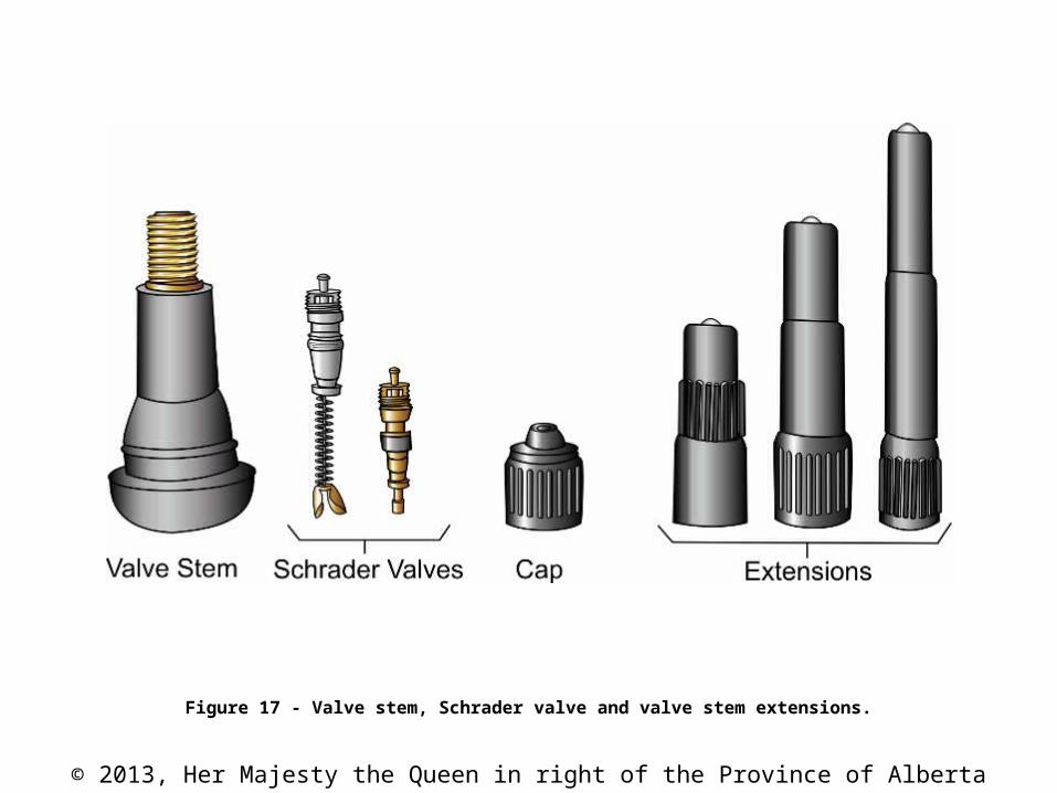
Figure 27 - Six-spoke wheel with a multi-piece rim assembly.(Courtesy Freightliner of Canada Ltd.)

© 2013, Her Majesty the Queen in right of the Province of Alberta
Figure 28 - Mounted hardware for spoke wheel.

© 2013, Her Majesty the Queen in right of the Province of Alberta
Figure 29 - 10-bolt disc wheel.

© 2013, Her Majesty the Queen in right of the Province of Alberta
Figure 30 - Hub designs with brake drums attached.(Courtesy General Motors of Canada Limited)

© 2013, Her Majesty the Queen in right of the Province of Alberta
Figure 31 - Installed spacer and samples used in a dual tire application.(Courtesy Freightliner of Canada Ltd.)
© 2013, Her Majesty the Queen in right of the Province of Alberta
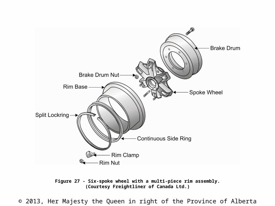
Figure 32 - Truck tire size.

© 2013, Her Majesty the Queen in right of the Province of Alberta
Figure 33 - Tire cross-section with measurements defined.(Courtesy Freightliner of Canada Ltd.)

© 2013, Her Majesty the Queen in right of the Province of Alberta
Figure 34 - Truck tire markings.

© 2013, Her Majesty the Queen in right of the Province of Alberta
Figure 35 - Wheel stud and tapered nut.(Courtesy Freightliner of Canada Ltd.)

© 2013, Her Majesty the Queen in right of the Province of Alberta
Figure 36 - Inner cap nut used to retain the inner wheel on a dual arrangement.(Courtesy Accuride Corporation)

© 2013, Her Majesty the Queen in right of the Province of Alberta
Figure 37 - Flange-style wheel nut.(Courtesy Freightliner of Canada Ltd.)

© 2013, Her Majesty the Queen in right of the Province of Alberta
CAUTION
Stud-piloted and hub-piloted disc wheels can have the same mounting bolt pattern. However, the retaining nuts are different and cannot be interchanged; otherwise, wheel damage or loss will occur.

© 2013, Her Majesty the Queen in right of the Province of Alberta
Figure 38 - Hub-piloted dual wheel arrangement with flange nut installed.(Courtesy Accuride Corporation)

© 2013, Her Majesty the Queen in right of the Province of Alberta
CAUTION
It is critical that the proper combination of wheels and retaining hardware be used to secure the wheels correctly and safely on the vehicle. Mixing wheel types or using the wrong type of fastener will cause wheel damage or wheel loss.
CAUTION
Do not mix aluminum stud-piloted and hub-piloted wheels or fasteners. Always use the specified wheel nuts; never substitute with standard stock hardware.

© 2013, Her Majesty the Queen in right of the Province of Alberta
Figure 39 - Static imbalance.(Courtesy Toyota Canada Inc.)

© 2013, Her Majesty the Queen in right of the Province of Alberta
NOTE
A wheel can be perfectly balanced statically and still be dynamically imbalanced.

© 2013, Her Majesty the Queen in right of the Province of Alberta
Figure 40 - Dynamic imbalance.(Courtesy Toyota Canada Inc.)

© 2013, Her Majesty the Queen in right of the Province of Alberta
Figure 41 - Wheel weight.

© 2013, Her Majesty the Queen in right of the Province of Alberta
Figure 42 - Tread depth gauge measurement.

© 2013, Her Majesty the Queen in right of the Province of Alberta
Figure 43 - Wear bars show through the tread on a worn tire.(Courtesy General Motors of Canada Limited)

© 2013, Her Majesty the Queen in right of the Province of Alberta
Figure 44 - Tire wear patterns.(Courtesy Toyota Canada Inc.)

© 2013, Her Majesty the Queen in right of the Province of Alberta
Figure 45 - Severe tire wear.

© 2013, Her Majesty the Queen in right of the Province of Alberta
Figure 46 - A plug-patch combination used to repair a punctured tire.

© 2013, Her Majesty the Queen in right of the Province of Alberta
NOTE
Tires with less than 1.6 mm (116") of tread remaining should never be repaired.

© 2013, Her Majesty the Queen in right of the Province of Alberta
Figure 47 - Tire rotation patterns.

© 2013, Her Majesty the Queen in right of the Province of Alberta
NOTE
Directional wheels, directional tires and some rims designed to fit front or rear only applications cannot be rotated. For these applications, the tires are normally removed and reinstalled at their new wheel positions.
Space-saver spare tires cannot be rotated since they are intended only for temporary use.
CAUTION
Radial tires and bias tires should never be mixed.

© 2013, Her Majesty the Queen in right of the Province of Alberta
NOTE
Before applying any tire warranty, always refer to the specifics of the tire manufacturer's and your store's policy on tire warranties.

© 2013, Her Majesty the Queen in right of the Province of Alberta
NOTE
Tire depth may vary depending on the manufacturer, brand and quality of the tire. Check tire manufacturer's specifications.

© 2013, Her Majesty the Queen in right of the Province of Alberta
Figure 48 - Tires stored vertically.

© 2013, Her Majesty the Queen in right of the Province of Alberta
Figure 49 - Tapered roller wheel bearings.

© 2013, Her Majesty the Queen in right of the Province of Alberta
Figure 50 - Wheel bearing disassembly.(Courtesy General Motors of Canada Limited)
© 2013, Her Majesty the Queen in right of the Province of Alberta
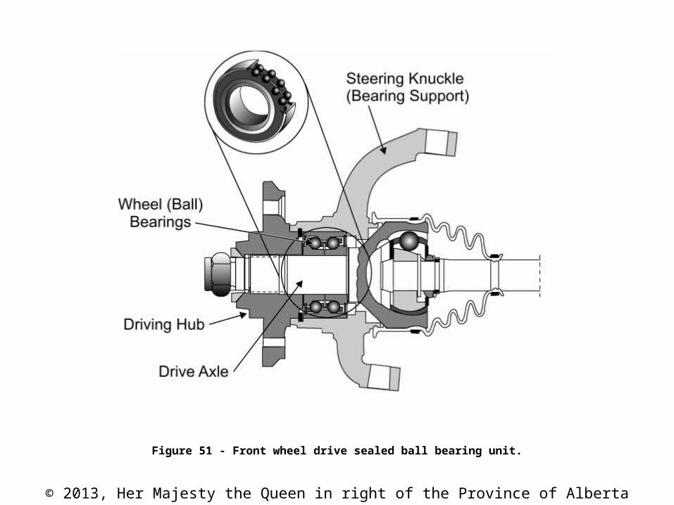
Figure 51 - Front wheel drive sealed ball bearing unit.

© 2013, Her Majesty the Queen in right of the Province of Alberta
Table 4 - Common replacement components and related sales.
Failed Component Related Sales
tires wheel tire balance (weights) bearings valve stem valve stem extensions tire cleaner
wheel tires tire balance (weights) tire cleaner wheel cleaner
wheel studs wheel nuts tire cleaner wheel cleaner
wheel bearing wheel bearing grease wheel seal
wheel seal wheel bearing grease wheel bearing

© 2013, Her Majesty the Queen in right of the Province of Alberta
Figure 52