Embed Size (px)
Citation preview

Wheel Support Assembly 1
Create all the components of the Wheel Support assembly and then assemble them, as shownin Figure 1. The dimensions of the components are shown in Figures 2 through 6.
Wheel Support Assembly
Figure 1 The Wheel Support assembly
Figure 9-3 Dimensions of the SupportFigure 2 Dimensions of the Base
Figure 5 Sectioned side view of the WheelFigure 4 Front view of the Wheel

2 Student Project
Figure 6 Dimensions of the Shoulder Screw, Bolt, Nut, Bushing,and Washer
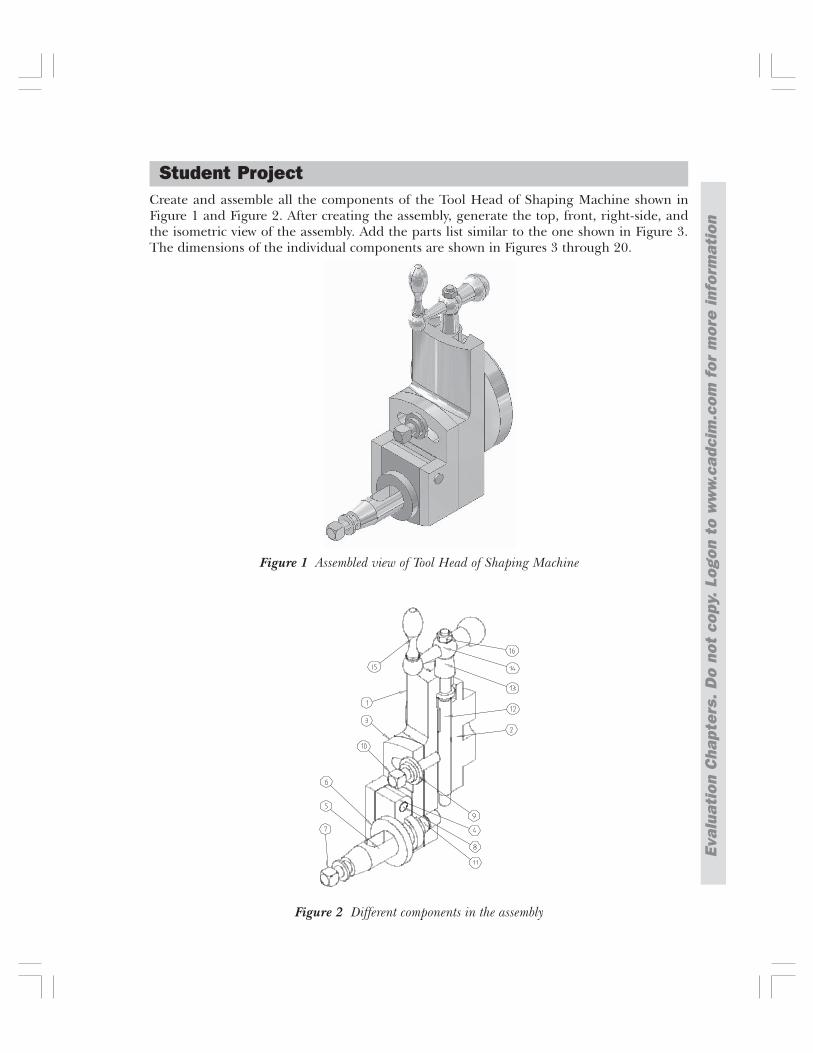
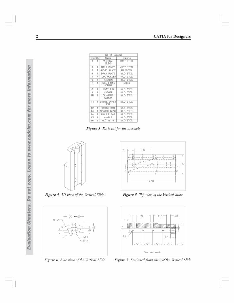
Create and assemble all the components of the Tool Head of Shaping Machine shown inFigure 1 and Figure 2. After creating the assembly, generate the top, front, right-side, andthe isometric view of the assembly. Add the parts list similar to the one shown in Figure 3.The dimensions of the individual components are shown in Figures 3 through 20.
Student Project
Figure 2 Different components in the assembly
Figure 1 Assembled view of Tool Head of Shaping Machine
Eval
uati
on C
hapt
ers.
Do
not
copy
. Log
on t
o w
ww
.cad
cim
.com
for
mor
e in
form
atio
n
2 CATIA for Designers
Eval
uati
on C
hapt
ers.
Do
not
copy
. Log
on t
o w
ww
.cad
cim
.com
for
mor
e in
form
atio
n
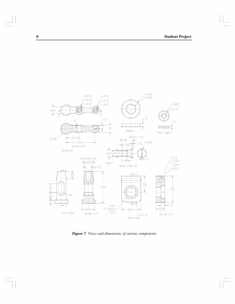
Figure 3 Parts list for the assembly
Figure 4 3D view of the Vertical Slide Figure 5 Top view of the Vertical Slide
Figure 6 Side view of the Vertical Slide Figure 7 Sectioned front view of the Vertical Slide

Student’s Project 3
Eval
uati
on C
hapt
ers.
Do
not
copy
. Log
on t
o w
ww
.cad
cim
.com
for
mor
e in
form
atio
n
Figure 12 Dimensions of the Handle Figure 13 Dimensions of the Handle Bar
Figure 10 3D view of the Back Plate Figure 11 Dimensions of the Tool Holder
Figure 8 Front view of the Back Plate Figure 9 Side view of the Back Plate

4 CATIA for Designers
Eval
uati
on C
hapt
ers.
Do
not
copy
. Log
on t
o w
ww
.cad
cim
.com
for
mor
e in
form
atio
n
Figure 14 Top view of the Swivel Plate Figure 15 Top view of the Drag Plate
Figure 16 Sectioned front view of the SwivelPlate
Figure 17 Sectioned front view of the Drag Plate
Figure 18 Dimensions of the components Figure 19 Dimensions of the components

Student’s Project 5
Eval
uati
on C
hapt
ers.
Do
not
copy
. Log
on t
o w
ww
.cad
cim
.com
for
mor
e in
form
atio
n
Figure 20 Dimensions of the components

Stock Bracket Assembly 1
Figure 2 Top and front views of the Stock Support Base
In this project, you will create the Stock Bracket assembly shown in Figure 1. The details ofthe components of the Stock Bracket assembly are shown in Figures 2 through 8.
Stock Bracket Assembly
Figure 1 The Stock Bracket assembly

2 Student Project
Figure 4 Top and front views of the Adjusting ScrewNut
Figure 3 Front and right-side views of the StockSupport Roller
Figure 6 Views of the Adjusting Nut Handle andAdjusting Screw Guide
Figure 5 Front and right-side views of the Support Roller Bracket

Stock Bracket Assembly 3
Figure 8 Top and front views of the ThrustBearing
Figure 7 Views of the Support Adjusting Screw

Shaper Tool Head Assembly 1
Create the Shaper Tool Head assembly, as shown in Figure 1. After creating the assembly, createits exploded view, as shown in Figure 2. The dimensions of the components are given inFigures 3 through 7.
Shaper Tool Head Assembly
Figure 1 The Shaper Tool Head assembly
Figure 2 The exploded view of the Shaper ToolHead assembly

2 Student Project
Figure 3 Views and dimensions of the Swivel Plate

Shaper Tool Head Assembly 3
Figure 4 Views and dimensions of the Back Plate

4 Student Project
Figure 5 Views and dimensions of the Vertical Slide

Shaper Tool Head Assembly 5
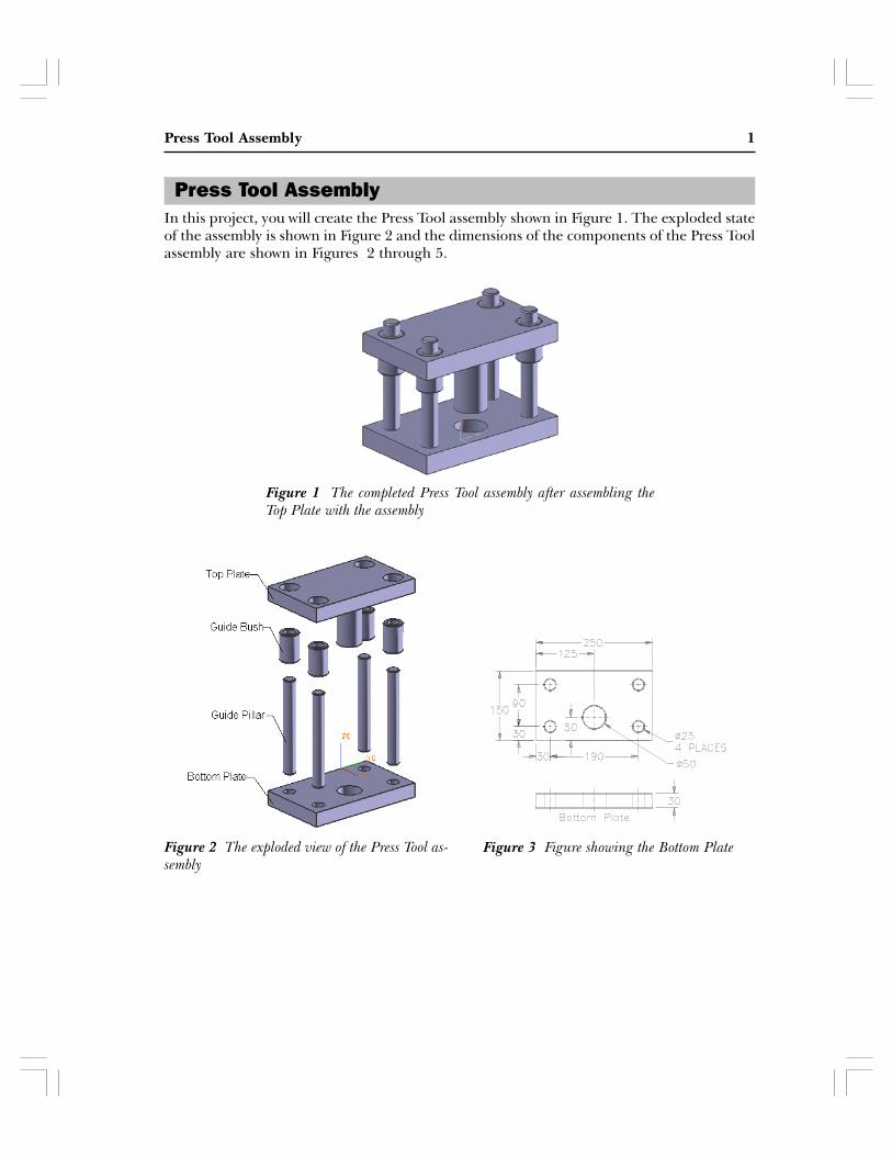
Figure 6 Views and dimensions of various components
6 Student Project
Figure 7 Views and dimensions of various components

Radial Engine Assembly 1
In this project, you will create the Radial Engine assembly shown in Figures 1 and 2. TheRadial Engine assembly will be created in two parts, one will be the subassembly and theother will be the main assembly. The dimensions of the components of the Radial Engineassembly are shown in Figures 3 through 6.
Radial Engine Assembly
Figure 1 The Radial Engine assembly Figure 2 The exploded view of the assembly
Figure 3 Views and dimensions of the Piston

2 Student Project
Figure 5 Views and dimensions of the Master Rod
Figure 4 Views and dimensions of the Articulated Rod

Radial Engine Assembly 3
Figure 6 Views and dimensions of the Rod Bush Upper, Rod Bush Lower, Piston Pin Plug,Piston Pin, Piston Rings, and Master Rod Bearing

Pulley Support Assembly 1
Figure 2 Exploded view of the Pulley Support assembly
Create the components of the Pulley Support assembly and then assemble them, as shown inFigure 1. After creating the assembly, create its exploded view, as shown in Figure 2. Thedimensions of the components are given in Figures 4 through 8.
Pulley Support Assembly
Figure 1 The Pulley Support assembly

2 Student Project
Figure 8 Dimensions of the Washer, Cap Screw, Turn Screw, and Nut
Figure 5 Dimensions of the BushingFigure 4 Dimensions of the Pulley
Figure 7 Sectioned front view of theFigure 6 Left-side view of the Bracket

Pulley Support Assembly 3
Figure 3 Parts list for the Pulley Support assembly
Press Tool Assembly 1
In this project, you will create the Press Tool assembly shown in Figure 1. The exploded stateof the assembly is shown in Figure 2 and the dimensions of the components of the Press Toolassembly are shown in Figures 2 through 5.
Press Tool Assembly
Figure 1 The completed Press Tool assembly after assembling theTop Plate with the assembly
Figure 2 The exploded view of the Press Tool as-sembly
Figure 3 Figure showing the Bottom Plate

2 Student Project
Figure 5 Dimensions and views of the Guide Pillarand Guide Bush
Figure 4 Dimensions and views of the TopPlate

Plummer Block Assembly 1
Figure 2 Views and dimensions of the Casting
In this project, you will create the components of the Plummer Block assembly, as shown inFigure 1 and then assemble them. The dimensions of the components are given in Figures 2through 4.
Plummer Block Assembly
Figure 1 The Plummer Block assembly

2 Student Project
Figure 3 Views and dimensions of the Cap
Figure 4 Views and dimensions of Brasses, Nut, Lock Nut, and Bolt

Pipe Vice Assembly 1
In this Project, you will create all components of the Pipe Vice assembly, as shown inFigure 1, and then assemble them. The dimensions of the components are given inFigures 2 and 3.
Figure 1 The Pipe Vice assembly
Pipe Vice Assembly
Figure 2 Views and dimensions of the Base

2 Student Project
Figure 3 Views and dimensions of the Screw, Handle, Movable Jaw, and Handle Screw
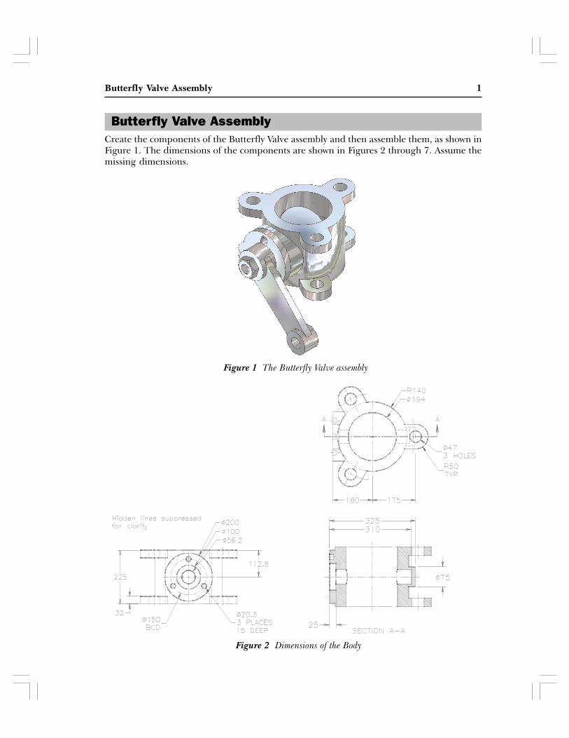
Butterfly Valve Assembly 1
Create the components of the Butterfly Valve assembly and then assemble them, as shown inFigure 1. The dimensions of the components are shown in Figures 2 through 7. Assume themissing dimensions.
Butterfly Valve Assembly
Figure 1 The Butterfly Valve assembly
Figure 2 Dimensions of the Body

2 Student Project
Figure 4 Dimensions of the RetainerFigure 3 Dimensions of the Shaft
Figure 6 Sectional front view of the ArmFigure 5 Top view of the Arm
Figure 7 Dimensions of the Plate, Nut, and Screw

Crosshead Assembly 1
Crosshead Assembly
Figure 2 The exploded state of Crosshead assembly
Figure 1 The Crosshead assembly
In this project, you will create all components of the Crosshead assembly and then assemblethem, as shown in Figure 1. Also you will create an exploded state, shown in Figure 2. Thedimensions of the components are shown in Figures 3 through 7.

2 Student Project
Figure 3 Front view and the right-side view of the Body
Figure 5 Dimensions of Piston RodFigure 4 Dimensions of Keep Plate
Figure 6 Dimensions of the Brasses and Bolt

Crosshead Assembly 3
Figure 7 Dimensions of Nut

Double Bearing Assembly 1
In this project, you will create the Double Bearing assembly shown in Figure 1. The explodedstate of the assembly is shown in Figure 2 and the dimensions of the components of theDouble Bearing assembly are shown in Figures 3 through 7.
Double Bearing Assembly
Figure 4 Top view of the CapFigure 3 Top view of the Base
Figure 2 The exploded view of the DoubleBearing assembly
Figure 1 The completed Double Bearingassembly
Figure 6 Front view of the CapFigure 5 Front view of the Base

2 Student Project
Figure 7 Dimensions and drawing views of the Bushing and the Bolt

Motor Blower Assembly 1
In this project, you will create the Motor Blower assembly shown in Figure 1. The explodedview of the assembly is shown in Figure 2. The details of the components of the Motor Blowerassembly are shown in Figures 3 through 8.
Figure 1 Motor Blower assembly
Figure 2 Exploded view of the Motor Blower assembly
Motor Blower Assembly

2 Student Project
Figure 3 Dimensions of the Upper Housing
Figure 4 Dimensions of the Lower Housing
Motor Blower Assembly 3
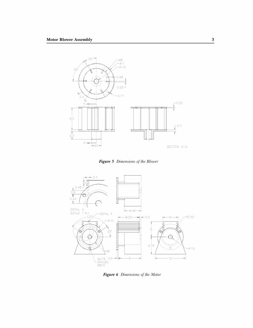
Figure 5 Dimensions of the Blower
Figure 6 Dimensions of the Motor

4 Student Project
Figure 8 Dimensions of the Shaft
Figure 7 Dimensions of the Cover

Bench Vice Assembly 1
In this project, you will create the Bench Vice assembly. Figures B through E shows the viewsand dimensions of the components of the Bench Vice assembly.
Bench Vice Assembly
Figure 2 Views and dimensions of the base
Figure 1 The Bench Vice assembly

2 Student Project
Figure 4 Views and dimensions of various components of the Bench Vice assembly
Figure 3 Views and dimensions of the Vice Jaw

Bench Vice Assembly 3
Figures 5 Views and dimensions of various components of the Bench Vice assembly