Embed Size (px)
Citation preview
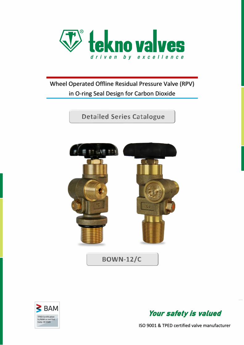
Wheel Operated Offline Residual Pressure Valve (RPV)
in O-ring Seal Design for Carbon Dioxide
ISO 9001 & TPED certified valve manufacturer
94
.5 a
Design Specifications Metric Unit *
✓ MIN life (main shut-off mechanism) : 2000 cycles
✓ MIN life (RPD) : 100000 cycles
✓ Closing-off pressure : 2 – 4 bar
✓ Opening pressure : 4 – 6 bar
✓ Main valve temperature range : -46 °C to +85°C
✓ RPD temperature range : -20° C to +65° C
✓ Minimum closing torque : 3 Nm
✓ Gland nut installation torque : 65 Nm
✓ RPD installation torque : 19 Nm
✓ PRD installation torque (if provided) : 32 Nm
✓ Stroke length : 5.00 – 5.50 mm
✓ Maximum test pressure (TP) : 360 bar
✓ Flow coefficient (Cv) : 0.45
✓ Lubricant (main shut-off mechanism) : Krytox ® GPL 225
✓ Lubricant (RPD) : Gleitmo 599
* Refer next page for English units
Testing & Certification ✓ Valves meet EN ISO 10297:2017 & EN ISO 15996:2017, tested by BAM
✓ Certified by BAM to European Transportable Pressure Equipment Directive (TPED) & available with mark
✓ Production testing as per EN ISO 14246
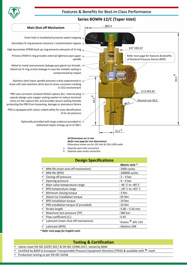
All Dimensions are in mm (Refer next page for inch dimensions) Dimensions shown are for 25E inlet & CGA 320R outlet
a Depends upon inlet connection b Depends upon outlet connection
.
Drain hole in handwheel prevents water trapping
Secondary O-ring prevents moisture / contamination ingress
High durometer EPDM back-up ring prevents extrusion of O-ring
Primary EPDM O-ring provides external tightness past upper spindle
Metal to metal seal prevents leakage past gland nut threads.
Gland nut O-ring arrests leakage in case the metallic sealing is
compromised by impact
Stainless steel lower spindle prevents cracks experienced in brass soft seal retention skirts due to stress corrosion cracking
in CO2 environment
PRD uses corrosion resistant Nickel rupture disc. Internal plug capsule design uses copper sealing washer to reduce torsional stress on the rupture disc and provides secure sealing thereby
protecting the PRD from loosening, damage or premature failure
PRD is equipped with colour coded safety for easy identification of its set pressure
Optionally provided with large undercut provided to withstand impact energy up to of 360 J
64
.5 a
Main Shut-off Mechanism
Refer next page for features & benefits of Residual Pressure Device (RPD)
Features & Benefits for Best-in-Class Performance
Series BOWN-12/C (Taper Inlet)
~ Ø65.0
Wrench size 30.0
31.5 b
3/4” HEX AF
12.0 HEX AF
Testing & Certification ✓ Valves meet EN ISO 10297:2017 & EN ISO 15996:2017, tested by BAM
✓ Certified by BAM to European Transportable Pressure Equipment Directive (TPED) & available with mark
✓ Production testing as per EN ISO 14246
4.8
2
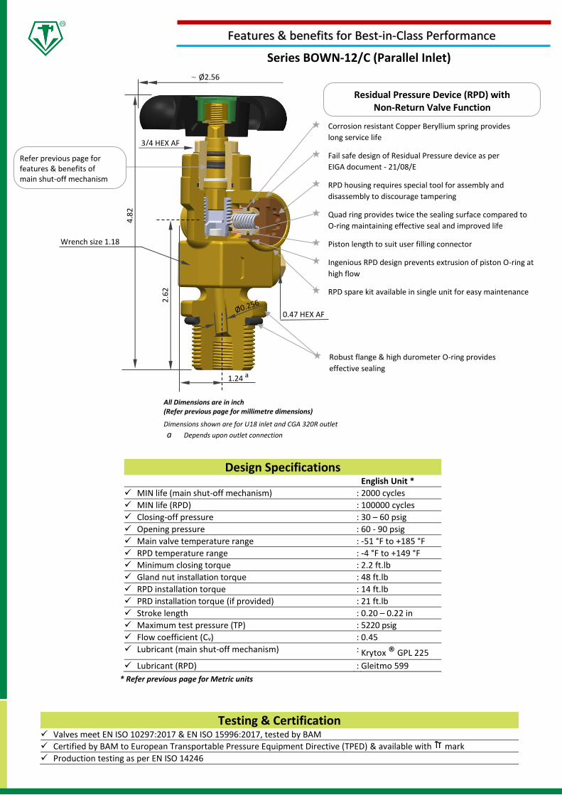
Design Specifications English Unit *
✓ MIN life (main shut-off mechanism) : 2000 cycles
✓ MIN life (RPD) : 100000 cycles
✓ Closing-off pressure : 30 – 60 psig
✓ Opening pressure : 60 - 90 psig
✓ Main valve temperature range : -51 °F to +185 °F
✓ RPD temperature range : -4 °F to +149 °F
✓ Minimum closing torque : 2.2 ft.lb
✓ Gland nut installation torque : 48 ft.lb
✓ RPD installation torque : 14 ft.lb
✓ PRD installation torque (if provided) : 21 ft.lb
✓ Stroke length : 0.20 – 0.22 in
✓ Maximum test pressure (TP) : 5220 psig
✓ Flow coefficient (Cv) : 0.45
✓ Lubricant (main shut-off mechanism) : Krytox ® GPL 225
✓ Lubricant (RPD) : Gleitmo 599
* Refer previous page for Metric units
.
Corrosion resistant Copper Beryllium spring provides
long service life
Fail safe design of Residual Pressure device as per
EIGA document - 21/08/E
RPD housing requires special tool for assembly and
disassembly to discourage tampering
Quad ring provides twice the sealing surface compared to
O-ring maintaining effective seal and improved life
Piston length to suit user filling connector
Ingenious RPD design prevents extrusion of piston O-ring at
high flow
RPD spare kit available in single unit for easy maintenance
Wrench size 1.18
1.24 a
2.6
2
3/4 HEX AF
0.47 HEX AF
Robust flange & high durometer O-ring provides
effective sealing
Residual Pressure Device (RPD) with Non-Return Valve Function
Features & benefits for Best-in-Class Performance
Refer previous page for features & benefits of main shut-off mechanism
All Dimensions are in inch (Refer previous page for millimetre dimensions)
Dimensions shown are for U18 inlet and CGA 320R outlet
a Depends upon outlet connection
Series BOWN-12/C (Parallel Inlet)
~ Ø2.56
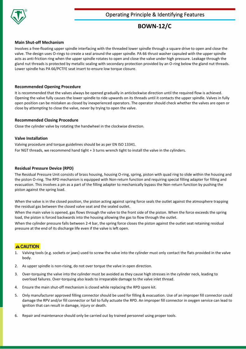
BOWN-12/C
Operating Principle & Identifying Features
Main Shut-off Mechanism
Involves a free-floating upper spindle interfacing with the threaded lower spindle through a square drive to open and close the valve. The design uses O-rings to create a seal around the upper spindle. PA 66 thrust washer capsuled with the upper spindle acts as anti-friction ring when the upper spindle rotates to open and close the valve under high pressure. Leakage through the gland nut threads is protected by metallic sealing with secondary protection provided by an O-ring below the gland nut threads. Lower spindle has PA 66/PCTFE seat insert to ensure low torque closure.
Recommended Opening Procedure
It is recommended that the valves always be opened gradually in anticlockwise direction until the required flow is achieved. Opening the valve fully causes the lower spindle to ride upwards on its threads until it contacts the upper spindle. Valves in fully open position can be mistaken as closed by inexperienced operators. The operator should check whether the valves are open or close by attempting to close the valve, never by trying to open the valve.
Recommended Closing Procedure
Close the cylinder valve by rotating the handwheel in the clockwise direction.
Valve Installation
Valving procedure and torque guidelines should be as per EN ISO 13341.
For NGT threads, we recommend hand tight + 3 turns wrench tight to install the valve in the cylinders.
Residual Pressure Device (RPD)
The Residual Pressure Unit consists of brass housing, housing O-ring, spring, piston with quad ring to slide within the housing and the piston O-ring. The RPD mechanism is equipped with Non-return function and requiring special filling adapter for filling and evacuation. This involves a pin as a part of the filling adapter to mechanically bypass the Non-return function by pushing the piston against the spring load.
When the valve is in the closed position, the piston acting against spring force seals the outlet against the atmosphere trapping the residual gas between the closed valve seat and the sealed outlet.
When the main valve is opened, gas flows through the valve to the front side of the piston. When the force exceeds the spring load, the piston is forced backwards into the housing allowing the gas to flow through the outlet.
When the cylinder pressure falls between 2-4 bar, the spring force closes the piston against the outlet seat retaining residual pressure at the end of its discharge life even if the valve is left open.
1. Valving tools (e.g. sockets or jaws) used to screw the valve into the cylinder must only contact the flats provided in the valve
body.
2. As upper spindle is non-rising, do not over torque the valve in open direction.
3. Over-torquing the valve into the cylinder must be avoided as they cause high stresses in the cylinder neck, leading to overload failures. Over-torquing also leads to irreparable damage to the valve inlet thread.
4. Ensure the main shut-off mechanism is closed while replacing the RPD spare kit.
5. Only manufacturer approved filling connector should be used for filling & evacuation. Use of an improper fill connector could damage the RPV and/or fill connector or fail to fully actuate the RPD. An improper fill connector in oxygen service can lead to ignition that can result in damage, injury or death.
6. Repair and maintenance should only be carried out by trained personnel using proper tools.
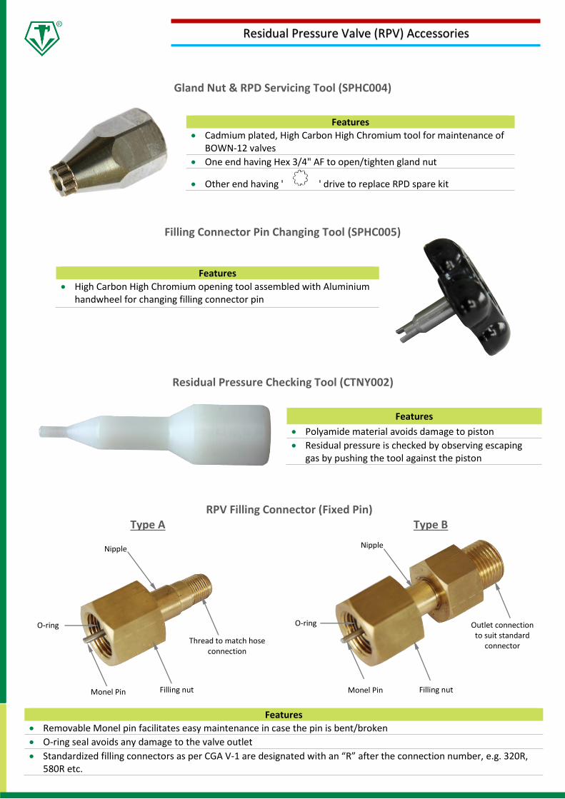
Residual Pressure Checking Tool (CTNY002)
Nipple
Gland Nut & RPD Servicing Tool (SPHC004)
Filling Connector Pin Changing Tool (SPHC005)
Thread to match hose connection
Filling nut Monel Pin
O-ring Outlet connection to suit standard
connector
Residual Pressure Valve (RPV) Accessories
Filling nut
Features
• Cadmium plated, High Carbon High Chromium tool for maintenance of BOWN-12 valves
• One end having Hex 3/4" AF to open/tighten gland nut
• Other end having ' ' drive to replace RPD spare kit
Monel Pin
O-ring
Features
• High Carbon High Chromium opening tool assembled with Aluminium handwheel for changing filling connector pin
RPV Filling Connector (Fixed Pin) Type A Type B
Features
• Removable Monel pin facilitates easy maintenance in case the pin is bent/broken
• O-ring seal avoids any damage to the valve outlet
• Standardized filling connectors as per CGA V-1 are designated with an “R” after the connection number, e.g. 320R, 580R etc.
Nipple
Features
• Polyamide material avoids damage to piston
• Residual pressure is checked by observing escaping gas by pushing the tool against the piston
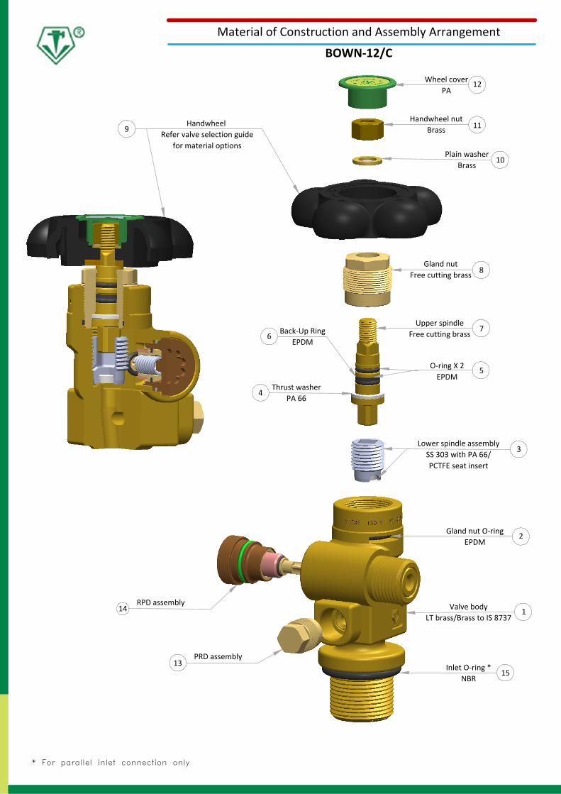
Handwheel Refer valve selection guide
for material options
9
15
2
4
5
7
8
6
13
14
12
3
Wheel coverPA
Handwheel nutBrass
Plain washerBrass
Gland nutFree cutting brass
Upper spindleFree cutting brass
O-ring X 2EPDM
Back-Up RingEPDM
Lower spindle assemblySS 303 with PA 66/PCTFE seat insert
Thrust washerPA 66
Gland nut O-ringEPDM
Valve bodyLT brass/Brass to IS 8737
PRD assembly
RPD assembly
* For parallel inlet connection only
Inlet O-ring *NBR
Material of Construction and Assembly Arrangement
BOWN-12/C
1
10
11
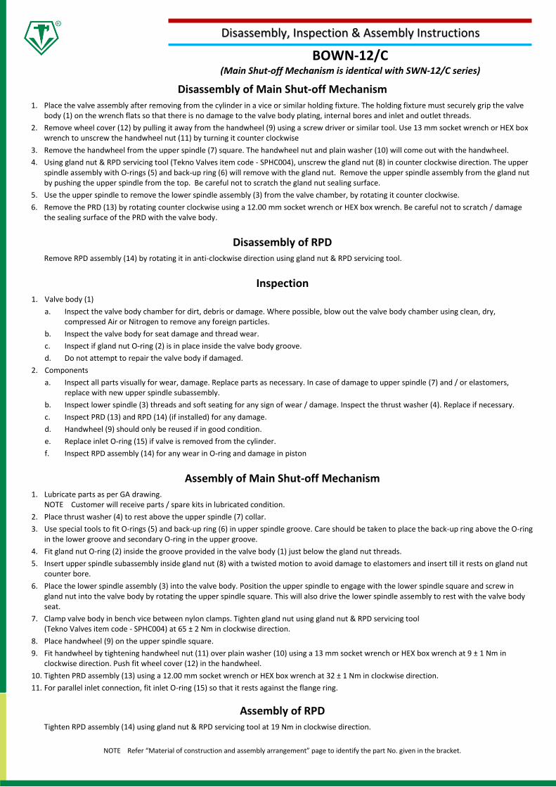
BOWN-12/C (Main Shut-off Mechanism is identical with SWN-12/C series)
Disassembly, Inspection & Assembly Instructions
Disassembly of Main Shut-off Mechanism 1. Place the valve assembly after removing from the cylinder in a vice or similar holding fixture. The holding fixture must securely grip the valve
body (1) on the wrench flats so that there is no damage to the valve body plating, internal bores and inlet and outlet threads.
2. Remove wheel cover (12) by pulling it away from the handwheel (9) using a screw driver or similar tool. Use 13 mm socket wrench or HEX box wrench to unscrew the handwheel nut (11) by turning it counter clockwise
3. Remove the handwheel from the upper spindle (7) square. The handwheel nut and plain washer (10) will come out with the handwheel.
4. Using gland nut & RPD servicing tool (Tekno Valves item code - SPHC004), unscrew the gland nut (8) in counter clockwise direction. The upper spindle assembly with O-rings (5) and back-up ring (6) will remove with the gland nut. Remove the upper spindle assembly from the gland nut by pushing the upper spindle from the top. Be careful not to scratch the gland nut sealing surface.
5. Use the upper spindle to remove the lower spindle assembly (3) from the valve chamber, by rotating it counter clockwise.
6. Remove the PRD (13) by rotating counter clockwise using a 12.00 mm socket wrench or HEX box wrench. Be careful not to scratch / damage the sealing surface of the PRD with the valve body.
Disassembly of RPD Remove RPD assembly (14) by rotating it in anti-clockwise direction using gland nut & RPD servicing tool.
Inspection 1. Valve body (1)
a. Inspect the valve body chamber for dirt, debris or damage. Where possible, blow out the valve body chamber using clean, dry, compressed Air or Nitrogen to remove any foreign particles.
b. Inspect the valve body for seat damage and thread wear.
c. Inspect if gland nut O-ring (2) is in place inside the valve body groove.
d. Do not attempt to repair the valve body if damaged.
2. Components
a. Inspect all parts visually for wear, damage. Replace parts as necessary. In case of damage to upper spindle (7) and / or elastomers, replace with new upper spindle subassembly.
b. Inspect lower spindle (3) threads and soft seating for any sign of wear / damage. Inspect the thrust washer (4). Replace if necessary.
c. Inspect PRD (13) and RPD (14) (if installed) for any damage.
d. Handwheel (9) should only be reused if in good condition.
e. Replace inlet O-ring (15) if valve is removed from the cylinder.
f. Inspect RPD assembly (14) for any wear in O-ring and damage in piston
Assembly of Main Shut-off Mechanism 1. Lubricate parts as per GA drawing.
NOTE Customer will receive parts / spare kits in lubricated condition.
2. Place thrust washer (4) to rest above the upper spindle (7) collar.
3. Use special tools to fit O-rings (5) and back-up ring (6) in upper spindle groove. Care should be taken to place the back-up ring above the O-ring in the lower groove and secondary O-ring in the upper groove.
4. Fit gland nut O-ring (2) inside the groove provided in the valve body (1) just below the gland nut threads.
5. Insert upper spindle subassembly inside gland nut (8) with a twisted motion to avoid damage to elastomers and insert till it rests on gland nut counter bore.
6. Place the lower spindle assembly (3) into the valve body. Position the upper spindle to engage with the lower spindle square and screw in gland nut into the valve body by rotating the upper spindle square. This will also drive the lower spindle assembly to rest with the valve body seat.
7. Clamp valve body in bench vice between nylon clamps. Tighten gland nut using gland nut & RPD servicing tool (Tekno Valves item code - SPHC004) at 65 ± 2 Nm in clockwise direction.
8. Place handwheel (9) on the upper spindle square.
9. Fit handwheel by tightening handwheel nut (11) over plain washer (10) using a 13 mm socket wrench or HEX box wrench at 9 ± 1 Nm in clockwise direction. Push fit wheel cover (12) in the handwheel.
10. Tighten PRD assembly (13) using a 12.00 mm socket wrench or HEX box wrench at 32 ± 1 Nm in clockwise direction.
11. For parallel inlet connection, fit inlet O-ring (15) so that it rests against the flange ring.
Assembly of RPD Tighten RPD assembly (14) using gland nut & RPD servicing tool at 19 Nm in clockwise direction.
NOTE Refer “Material of construction and assembly arrangement” page to identify the part No. given in the bracket.
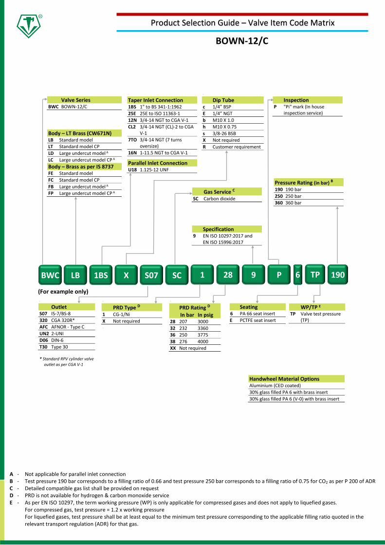
(For example only)
.
PRD Type D 1 CG-1/Ni
X Not required .
.
Outlet S07 IS-7/BS-8
320 CGA 320R*
AFC AFNOR - Type C
UN2 2-UNI
D06 DIN-6
T30 Type 30 .
* Standard RPV cylinder valve
outlet as per CGA V-1
Seating 6 PA 66 seat insert
E PCTFE seat insert
.
PRD Rating D In bar In psig 28 207 3000
32 232 3360
36 250 3775
38 276 4000
XX Not required
WP/TP E TP Valve test pressure
(TP)
Handwheel Material Options Aluminium (CED coated)
30% glass filled PA 6 with brass insert
30% glass filled PA 6 (V-0) with brass insert
A - Not applicable for parallel inlet connection B - Test pressure 190 bar corresponds to a filling ratio of 0.66 and test pressure 250 bar corresponds to a filling ratio of 0.75 for CO2 as per P 200 of ADR C - Detailed compatible gas list shall be provided on request D - PRD is not available for hydrogen & carbon monoxide service E - As per EN ISO 10297, the term working pressure (WP) is only applicable for compressed gases and does not apply to liquefied gases.
For compressed gas, test pressure = 1.2 x working pressure For liquefied gases, test pressure shall be at least equal to the minimum test pressure corresponding to the applicable filling ratio quoted in the relevant transport regulation (ADR) for that gas.
BWC LB 1BS X S07 SC 1 28 9 P 6 190
Valve Series BWC BOWN-12/C
.
Dip Tube c 1/4” BSP
E 1/4” NGT
b M10 X 1.0
h M10 X 0.75
s 3/8-26 BSB
X Not required
R Customer requirement .
.
Taper Inlet Connection 1BS 1" to BS 341-1:1962
25E 25E to ISO 11363-1
12N 3/4-14 NGT to CGA V-1
CL2 3/4-14 NGT (CL)-2 to CGA V-1
7TO 3/4-14 NGT (7 turns oversize)
16N 1-11.5 NGT to CGA V-1
Parallel Inlet Connection U18 1.125-12 UNF
Body – LT Brass (CW671N) LB Standard model
LT Standard model CP
LD Large undercut model A
LC Large undercut model CP A
Body – Brass as per IS 8737 FE Standard model
FC Standard model CP
FB Large undercut model A
FP Large undercut model CP A
Inspection P "Pi" mark (In house
inspection service)
Pressure Rating (in bar) B 190 190 bar
250 250 bar
360 360 bar
Gas Service C SC Carbon dioxide
Specification 9 EN ISO 10297:2017 and
EN ISO 15996:2017
TP
BOWN-12/C
Product Selection Guide – Valve Item Code Matrix
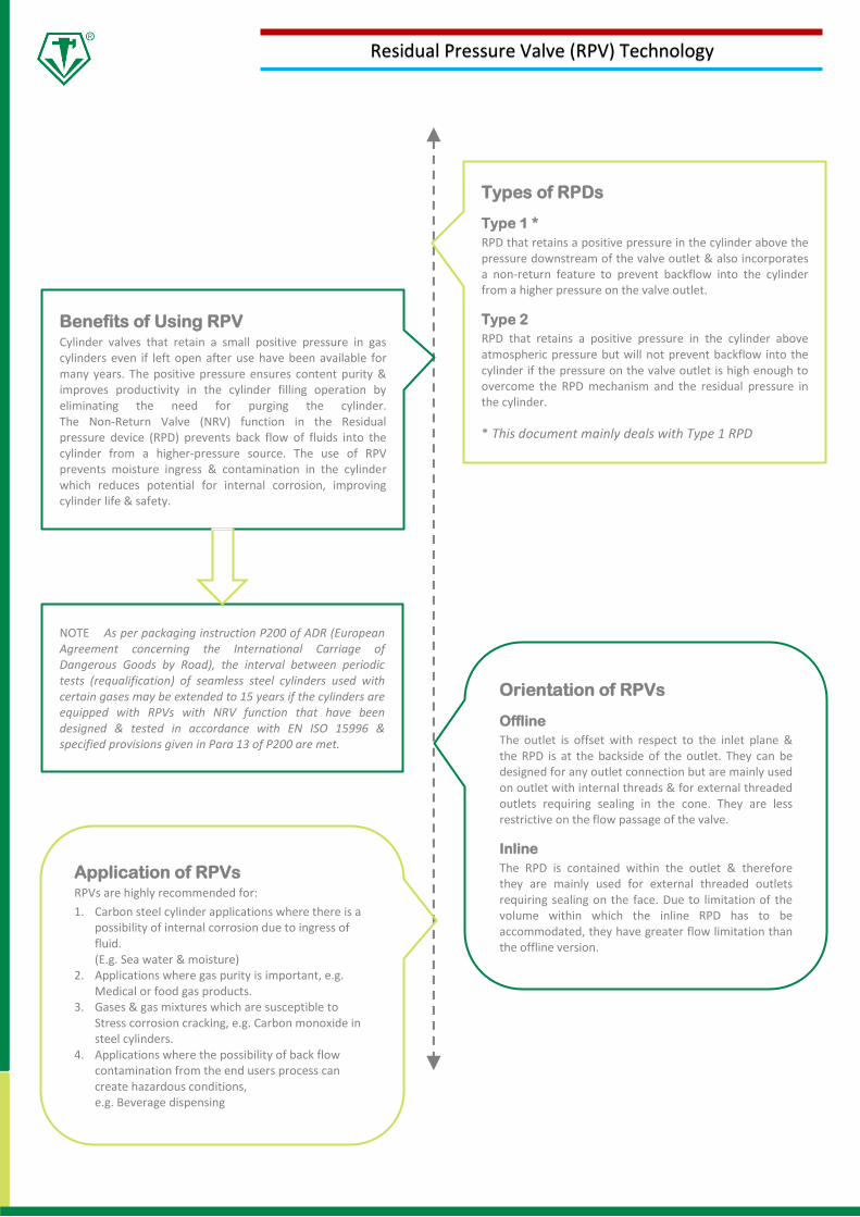
Application of RPVs RPVs are highly recommended for:
1. Carbon steel cylinder applications where there is a possibility of internal corrosion due to ingress of fluid. (E.g. Sea water & moisture)
2. Applications where gas purity is important, e.g. Medical or food gas products.
3. Gases & gas mixtures which are susceptible to Stress corrosion cracking, e.g. Carbon monoxide in steel cylinders.
4. Applications where the possibility of back flow contamination from the end users process can create hazardous conditions, e.g. Beverage dispensing
Orientation of RPVs
Offline
The outlet is offset with respect to the inlet plane & the RPD is at the backside of the outlet. They can be designed for any outlet connection but are mainly used on outlet with internal threads & for external threaded outlets requiring sealing in the cone. They are less restrictive on the flow passage of the valve.
Inline
The RPD is contained within the outlet & therefore they are mainly used for external threaded outlets requiring sealing on the face. Due to limitation of the volume within which the inline RPD has to be accommodated, they have greater flow limitation than the offline version.
Residual Pressure Valve (RPV) Technology
Benefits of Using RPV Cylinder valves that retain a small positive pressure in gas cylinders even if left open after use have been available for many years. The positive pressure ensures content purity & improves productivity in the cylinder filling operation by eliminating the need for purging the cylinder. The Non-Return Valve (NRV) function in the Residual pressure device (RPD) prevents back flow of fluids into the cylinder from a higher-pressure source. The use of RPV prevents moisture ingress & contamination in the cylinder which reduces potential for internal corrosion, improving cylinder life & safety.
NOTE As per packaging instruction P200 of ADR (European Agreement concerning the International Carriage of Dangerous Goods by Road), the interval between periodic tests (requalification) of seamless steel cylinders used with certain gases may be extended to 15 years if the cylinders are equipped with RPVs with NRV function that have been designed & tested in accordance with EN ISO 15996 & specified provisions given in Para 13 of P200 are met.
Types of RPDs
Type 1 *
RPD that retains a positive pressure in the cylinder above the pressure downstream of the valve outlet & also incorporates a non-return feature to prevent backflow into the cylinder from a higher pressure on the valve outlet.
Type 2
RPD that retains a positive pressure in the cylinder above atmospheric pressure but will not prevent backflow into the cylinder if the pressure on the valve outlet is high enough to overcome the RPD mechanism and the residual pressure in the cylinder.
* This document mainly deals with Type 1 RPD
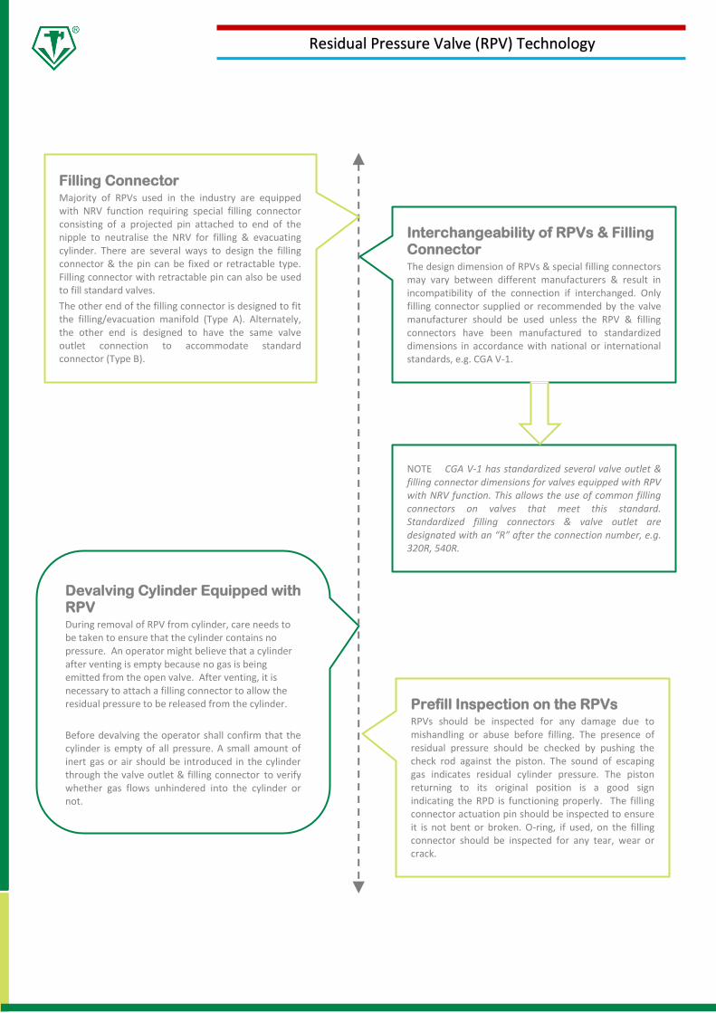
Prefill Inspection on the RPVs RPVs should be inspected for any damage due to mishandling or abuse before filling. The presence of residual pressure should be checked by pushing the check rod against the piston. The sound of escaping gas indicates residual cylinder pressure. The piston returning to its original position is a good sign indicating the RPD is functioning properly. The filling connector actuation pin should be inspected to ensure it is not bent or broken. O-ring, if used, on the filling connector should be inspected for any tear, wear or crack.
Devalving Cylinder Equipped with RPV During removal of RPV from cylinder, care needs to be taken to ensure that the cylinder contains no pressure. An operator might believe that a cylinder after venting is empty because no gas is being emitted from the open valve. After venting, it is necessary to attach a filling connector to allow the residual pressure to be released from the cylinder.
Before devalving the operator shall confirm that the cylinder is empty of all pressure. A small amount of inert gas or air should be introduced in the cylinder through the valve outlet & filling connector to verify whether gas flows unhindered into the cylinder or not.
Residual Pressure Valve (RPV) Technology
Interchangeability of RPVs & Filling Connector The design dimension of RPVs & special filling connectors may vary between different manufacturers & result in incompatibility of the connection if interchanged. Only filling connector supplied or recommended by the valve manufacturer should be used unless the RPV & filling connectors have been manufactured to standardized dimensions in accordance with national or international standards, e.g. CGA V-1.
NOTE CGA V-1 has standardized several valve outlet & filling connector dimensions for valves equipped with RPV with NRV function. This allows the use of common filling connectors on valves that meet this standard. Standardized filling connectors & valve outlet are designated with an “R” after the connection number, e.g. 320R, 540R.
Filling Connector Majority of RPVs used in the industry are equipped with NRV function requiring special filling connector consisting of a projected pin attached to end of the nipple to neutralise the NRV for filling & evacuating cylinder. There are several ways to design the filling connector & the pin can be fixed or retractable type. Filling connector with retractable pin can also be used to fill standard valves.
The other end of the filling connector is designed to fit the filling/evacuation manifold (Type A). Alternately, the other end is designed to have the same valve outlet connection to accommodate standard connector (Type B).

INDIA Natun Rasta, Bilkanda
24 Parganas (N)
Kolkata, WB
+91-33-25956767
www.teknovalves.com
NORTH AMERICA Tekno Valves North America, Inc
8480 Athens Ave, Baton Rouge, Louisiana, LA, USA
(225) 330 - 6590
www.tvnainc.com
EUROPE GBP Gas Business Partner GmbH
Auf der Mühle 14
D-35232 Dautphetal, Germany
+49-6468-9179952
www.gas-business-partner.com
Last updated: 23rd November 2019 P.Halder