Embed Size (px)
Citation preview

L 550-586_BILD_Kompl.indd 1L 550-586_BILD_Kompl.indd 1 01.08.2007 18:30:08 Uhr01.08.2007 18:30:08 Uhr
Tipping load, articulated: 11,650 kg – 20,430 kg
Wheel Loaders L 550 - L 5862plus22plus2
design
bauma –German construction industry
innovation award
2007
L 550-586_GB.indd 1L 550-586_GB.indd 1 02.08.2007 12:59:24 Uhr02.08.2007 12:59:24 Uhr
2
L 550-586_BILD_Kompl.indd 2L 550-586_BILD_Kompl.indd 2 01.08.2007 18:30:11 Uhr01.08.2007 18:30:11 Uhr
L 550 2plus2 – L 586 2plus2
L 550 2plus2
Tipping load, articulated: 11,650 kgBucket capacity: 3.2 m³Operating weight: 16,525 kgEngine output: 130 kW
L 556 2plus2
Tipping load, articulated: 13,140 kgBucket capacity: 3.6 m³Operating weight: 17,270 kgEngine output: 140 kW
L 566 2plus2
Tipping load, articulated: 15,550 kg Bucket capacity: 4.0 m³ Operating weight: 22,500 kgEngine output: 190 kW
L 576 2plus2
Tipping load, articulated: 17,200 kgBucket capacity: 4.5 m³Operating weight: 24,260 kgEngine output: 200 kW
L 580 2plus2
Tipping load, articulated: 18,000 kgBucket capacity: 5.0 m³Operating weight: 24,580 kgEngine output: 200 kW
L 586 2plus2
Tipping load, articulated: 20,430 kgBucket capacity: 5.5 m³Operating weight: 31,380 kgEngine output: 250 kW
L 550-586_GB.indd 2L 550-586_GB.indd 2 02.08.2007 12:59:24 Uhr02.08.2007 12:59:24 Uhr

3
L 550-586_BILD_Kompl.indd 3L 550-586_BILD_Kompl.indd 3 01.08.2007 18:30:12 Uhr01.08.2007 18:30:12 Uhr
L 550 2plus2 – L 586 2plus2
Economy Compared to conventional travel gears, the Liebherr driveline achieves a reduction in fuel consumption for wheel loaders of 25 % or more! 5 litres less fuel per oper-ating hour signifi cantly reduce operating costs and envi-ronmental pollution.
PerformanceThe Liebherr driveline allows the Liebherr diesel engine to be mounted lengthways in the rear, with the output shaft facing backwards. Compared to conventionally driven wheel loaders, the operating weight is much lower, the tipping load is higher, and more material can be moved each operating hour.
ReliabilityAll the materials used in Liebherr wheel loaders have passed long-term tests to ensure that they match up to Liebherr’s exacting standards even in the toughest con-ditions. The mature concept and proven quality make Liebherr wheel loaders to the benchmark for reliability.
ComfortThe ultra-modern cab design with advanced ergonom-ics, continuously variable Liebherr driveline with 2plus2 gearbox for uninterrupted tractive force, standard Liebherr ride control, optimum weight distribution and easy service access thanks to unique engine installa-tion position lead to extraordinary overall comfort.
L 550-586_GB.indd 3L 550-586_GB.indd 3 02.08.2007 12:59:25 Uhr02.08.2007 12:59:25 Uhr
4
2
5
4
3
115
20
25
30
35n=?
20m
T ~
35
sec.
2,5
m
A
B
L 550-586_BILD_Kompl.indd 4L 550-586_BILD_Kompl.indd 4 01.08.2007 18:30:12 Uhr01.08.2007 18:30:12 Uhr
L 550 2plus2 – L 586 2plus2
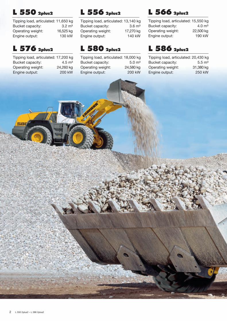
Lower fuel consumption
• Up to 5 litres less consumption per operating hour, a fuel saving of up to 25 %.
• The Liebherr wheel loaders dem-onstrate their fuel economy in the Liebherr standard Normtest.
L 550-586_GB.indd 4L 550-586_GB.indd 4 02.08.2007 12:59:25 Uhr02.08.2007 12:59:25 Uhr

5
L 550-586_BILD_Kompl.indd 5L 550-586_BILD_Kompl.indd 5 01.08.2007 18:30:13 Uhr01.08.2007 18:30:13 Uhr
L 550 2plus2 – L 586 2plus2
Economy
Compared to conventional travel gears, the Liebherr driveline achieves a reduc-tion in fuel consumption for wheel loaders of 25 % or more! 5 litres less fuel per operating hour signifi cantly reduce operating costs and environmental pollution.
Low operating costsMinimum costs, High handling capacity
Liebherr wheel loaders are unbeatable for econ-omy compared to conventionally driven wheel loaders. This is due to the following factors:
− Low fuel consumption thanks to higher effi -ciency and low operating weight. Liebherr wheel loaders need up to 5 litres less fuel per operat-ing hour at the same working conditions.
− More or less no brake wear thanks to the hydrau-lic braking action of the driveline. This means there is practically no brake wear and conse-quent repair costs.
− Reduced tyre wear thanks to continuous trac-tion control. Depending on the working condi-tions, there is up to 25 % less wear.
Active environmental protectionEconomical use of resources
The reduction in fuel lowers emissions, thus actively protecting resources:1 litre of fuel produces up to 3 kg of carbon diox-ide (CO2). By saving up to 5 litres per operating hour, up to 15,000 kg less CO2 is produced in 1,000 operating hours – that means lower costs and active environmental protection.
Low noise emission The innovative driveline concept means much lower noise emission – Liebherr wheel loaders are signifi cantly quieter in operation.
Reduced brake wear
• Even under the toughest working condi-tions, the Liebherr travel drive always brakes hydraulically. The mechanical service brake only acts as a support and is therefore subject to hardly any wear.
Reduced tyre wear
• The tractive force can be adjusted con-tinuously. This stops wheel spins and reduced tyre wear by up to 25 %.
L 550-586_GB.indd 5L 550-586_GB.indd 5 02.08.2007 12:59:25 Uhr02.08.2007 12:59:25 Uhr

6
L 550-586_BILD_Kompl.indd 6L 550-586_BILD_Kompl.indd 6 01.08.2007 18:30:13 Uhr01.08.2007 18:30:13 Uhr
L 550 2plus2 – L 586 2plus2
Liebherr driveline
• Optimum weight distribution thanks to lengthways-installed Liebherr diesel engine, output shaft is facing to the rear.
• The variable displacement pumps on the engine act as counterweight, thus allow-ing higher tipping loads at low operating weight.
• Compact design improves visibility in all directions
L 550-586_GB.indd 6L 550-586_GB.indd 6 02.08.2007 12:59:26 Uhr02.08.2007 12:59:26 Uhr

7
L 550-586_BILD_Kompl.indd 7L 550-586_BILD_Kompl.indd 7 01.08.2007 18:30:14 Uhr01.08.2007 18:30:14 Uhr
L 550 2plus2 – L 586 2plus2
Performance
The Liebherr driveline allows the Liebherr diesel engine to be mounted length-ways in the rear, with the output shaft facing backwards. Compared to conven-tionally driven wheel loaders, the operating weight is much lower, the tipping load is higher, and more material can be moved each operating hour.
Higher performance, lower weightHigher productivity The combination of the Liebherr driveline and the
unique position of the Liebherr diesel engine allows higher tipping loads at low operating weight. This leads to signifi cantly higher productivity, because there is no need for unnecessary counterweight.
Ultra modern Liebherr drivelineInnovative technology The large Liebherr wheel loaders are equipped
with the 2plus2 gearbox. Tractive force and speed are automatically adjusted to the requirements of the operator without shifting. There is no need for a mechanical reverse gear because the travel direction is changed hydraulically.
Flexibility puts them aheadAn all-purpose loader The “Holzknecht” is the ideal tool to complement
the available equipment for the large Liebherr wheel loaders. Especially when operating with heavy equipment and loads, this “torque increase” is the perfect additional system for your require-ments. Their compact design allows these wheel loaders to maneuver quickly and effi ciently – an ideal basis for high handling capacity.
Conventional travel gear
• Longitudinally mounted diesel engine moves the center of gravity to the further forward
• Additional counterweight is needed to maintain stability and to increase the tipping load.
• This results in high operating weight and bad visibility
An all-purpose loader
• The choice between “Holzknecht” or Z pattern linkage means that the loader can always be confi gured for every job application – Holzknecht for industrial use; Z for conventional material handling.
L 550-586_GB.indd 7L 550-586_GB.indd 7 02.08.2007 12:59:26 Uhr02.08.2007 12:59:26 Uhr

8
L 550-586_BILD_Kompl.indd 8L 550-586_BILD_Kompl.indd 8 01.08.2007 18:30:14 Uhr01.08.2007 18:30:14 Uhr
L 550 2plus2 – L 586 2plus2
Liebherr driveline
• The Liebherr driveline consists of two hydraulic motors which accel-erate the loader continuously from a standstill to maximum speed, either forwards or in reverse – with a 2plus2 gearbox – but without a reversing gear unit.
L 550-586_GB.indd 8L 550-586_GB.indd 8 02.08.2007 12:59:26 Uhr02.08.2007 12:59:26 Uhr
9
L 550-586_BILD_Kompl.indd 9L 550-586_BILD_Kompl.indd 9 01.08.2007 18:30:15 Uhr01.08.2007 18:30:15 Uhr
L 550 2plus2 – L 586 2plus2
Reliability
All the materials used in Liebherr wheel loaders have passed long term tests to ensure that they meet Liebherr’s exacting standards even in the toughest condi-tions. The mature concept and proven quality make Liebherr wheel loaders to the benchmark for reliability.
Reliable Liebherr drivelineFewer components The Liebherr driveline includes a self-locking
hydraulic brake, which means the additional wet brake discs are effectively wear-free. There is no need for a reversing gear unit – thus minimizing the number of parts susceptible to wear.
Controlled coolingThe intelligent answer The cooling fan is not driven directly from the
Liebherr diesel engine, and produces only the cool-ing air output which is actually required. Heat sen-sors ensure reliable control. If overheating should occur, the wheel loader automatically shifts down to fi rst travel speed range. The reduced power con-sumption protects the engine from overheating. At the same time, the fan speed is increased to maxi-mum value, thus preventing the engine from over-heating.
Components meet manufacturer’s quality standardsEverything from a single source
Important components such as the engine, hydrau-lic rams and electronics are developed and manu-factured by Liebherr itself. This ensures co-ordi-nated quality from the manufacturer down to the smallest detail. Liebherr components guarantee maximum performance and reliability.
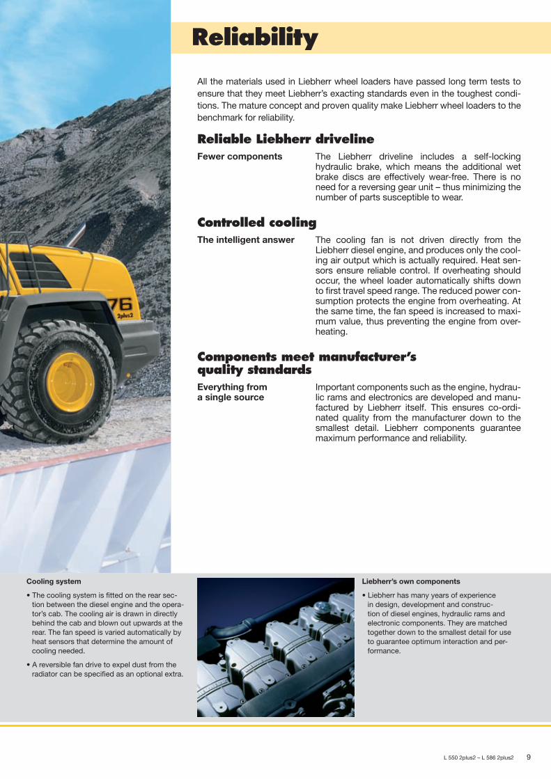
Cooling system
• The cooling system is fi tted on the rear sec-tion between the diesel engine and the opera-tor’s cab. The cooling air is drawn in directly behind the cab and blown out upwards at the rear. The fan speed is varied automatically by heat sensors that determine the amount of cooling needed.
• A reversible fan drive to expel dust from the radiator can be specifi ed as an optional extra.
Liebherr’s own components
• Liebherr has many years of experience in design, development and construc-tion of diesel engines, hydraulic rams and electronic components. They are matched together down to the smallest detail for use to guarantee optimum interaction and per-formance.
L 550-586_GB.indd 9L 550-586_GB.indd 9 02.08.2007 12:59:26 Uhr02.08.2007 12:59:26 Uhr

10
–
–
–
–
–
–
L 550-586_BILD_Kompl.indd 10L 550-586_BILD_Kompl.indd 10 01.08.2007 18:30:16 Uhr01.08.2007 18:30:16 Uhr
L 550 2plus2 – L 586 2plus2
Liebherr control lever
• The Liebherr control lever is used to manage all travel and work-ing movements of the wheel loader, so that the operator’s left hand can always remain on the steering wheel. There is no need to let go of the steering wheel, and this increases the safety. The operator controls the following functions with his right hand:
Raise and lower attachment
Fill and dump the bucket
Automatic bucket return to dig
Kick down and Gear Hold function
Auxiliary control buttons for additional hydraulic functions
Change of travel direction with simultaneous travel start
L 550-586_GB.indd 10L 550-586_GB.indd 10 02.08.2007 12:59:27 Uhr02.08.2007 12:59:27 Uhr

11
–
–
–
–
L 550-586_BILD_Kompl.indd 11L 550-586_BILD_Kompl.indd 11 01.08.2007 18:30:17 Uhr01.08.2007 18:30:17 Uhr
L 550 2plus2 – L 586 2plus2
Comfort
Service access
• The unique position of the Liebherr diesel engine provides perfect accessibility for main-tenance. The hydraulic pumps, hydraulic tank, hydraulic tank cut-off valve and battery main switch can be easily and safely accessed from ground level by opening a single engine com-partment hood.
Powerful air-conditioning system
• The standard equipped air-conditioning system of the large wheel loaders provides the greatest operator comfort for high productivity.
• The air fl ow is controlled at 4 different levels – an automatic air-conditioning system is avail-able as an option.
Air fl ow in the feet area
Defroster
Air fl ow in the head area
Air fl ow in the body area
The ultra modern cab design with advanced ergonomics, continuously variable Liebherr driveline with 2plus2 gearbox for uninterrupted tractive force, standard Liebherr ride control, optimum weight distribution and easy service access thanks to unique engine installation position lead to extraordinary overall comfort.
Top-class cabin designComfort cab The ultra-modern, ergonomically planned cabin
design allows the operator to achieve better per-formance and productivity in the greatest possible comfort. The displays, controls and operator’s seat are carefully coordinated to form a perfect ergo-nomic unit.
Liebherr control lever All the working and travel functions are operated precisely and sensitively from a single control lever. This means accurate and safe handling, and the left hand always remains on the steering wheel. This increases the safety at the job site.
Liebherr drivelineContinuously variable transmission
The Liebherr driveline with its 2plus2 gearbox al-lows continuous regulation of acceleration in all speed ranges, without noticeable gear shifting or interruption in tractive force.
Service accessEasy maintenance Because the Liebherr diesel engine is rotated by
180°, the hydraulic pumps, hydraulic tank, hydraulic tank cut-off valve, air fi lter and battery main switch can be reached easily and safely from ground level by opening a single engine compartment hood. The engine, pump distributor gear and cooling system are easily accessible by opening the engine cover.
Hydrostatic fan drive The cooling system is positioned directly behind the cab, which means there is less dirt and there-fore less maintenance and cleaning resulting in time and cost savings!
L 550-586_GB.indd 11L 550-586_GB.indd 11 02.08.2007 12:59:27 Uhr02.08.2007 12:59:27 Uhr
12 L 550 2plus2 – L 586 2plus2
Technical DataL
550 – L 5
80
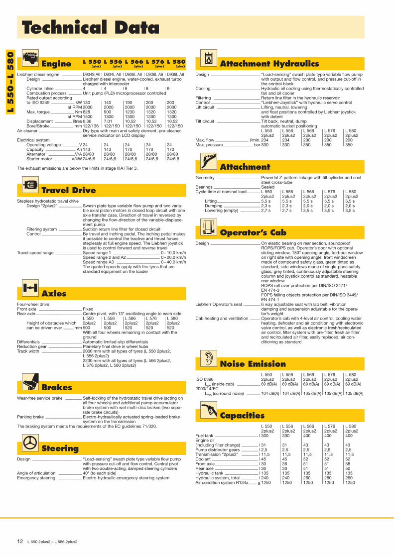
Engine 2plus2 2plus2 2plus2 2plus2 2plus2
Liebherr diesel engine ____________ D934S A6 D934L A6 D936L A6 D936L A6 D936L A6Design ________________________ Liebherr diesel engine, water-cooled, exhaust turbo
charged with intercoolerCylinder inline ________________ 4 4 6 6 6Combustion process ________ Unit pump (PLD) microprocessor controlledRated output accordingto ISO 9249 ______________ kW 130 140 190 200 200
at RPM 2000 2000 2000 2000 2000Max. torque ______________ Nm 828 900 1230 1320 1320
at RPM 1500 1300 1300 1300 1300Displacement __________ litres 6,36 7,01 10,52 10,52 10,52Bore/Stroke ______________ mm 122/136 122/150 122/150 122/150 122/150
Air cleaner __________________________ Dry type with main and safety element, pre-cleaner,service indicator on LCD display
Electrical systemOperating voltage __________V 24 24 24 24 24Capacity __________________ Ah 143 143 170 170 170Alternator ________________V/A 28/80 28/80 28/80 28/80 28/80Starter motor __________V/kW 24/6,6 24/6,6 24/6,6 24/6,6 24/6,6
The exhaust emissions are below the limits in stage IIIA / Tier 3.
L 550 L 556 L 566 L 576 L 580
SteeringDesign ______________________________ “Load-sensing” swash plate type variable flow pump
with pressure cut-off and flow control. Central pivotwith two double-acting, damped steering cylinders
Angle of articulation ______________ 40° (to each side)Emergency steering ______________ Electro-hydraulic emergency steering system
Operator’s CabDesign ______________________________ On elastic bearing on rear section, soundproof
ROPS/FOPS cab. Operator’s door with optional sliding window, 180° opening angle, fold-out windowon right site with opening angle, front windscreenmade of compound safety glass, green tinted asstandard, side windows made of single-pane safetyglass, grey tinted, continuously adjustable steeringcolumn and joystick control as standard, heatablerear windowROPS roll over protection per DIN/ISO 3471/EN 474-3FOPS falling objects protection per DIN/ISO 3449/EN 474-1
Liebherr Operator’s seat __________ 6 way adjustable seat with lap belt, vibration damping and suspension adjustable for the opera -tor’s weight
Cab heating and ventilation ______ Operator’s cab with 4-level air control, cooling waterheating, defroster and air conditioning with electronicvalve control, as well as electronic fresh/recirculatedair control, filter system with pre-filter, fresh air filterand recirculated air filter, easily replaced, air con -ditioning as standard
AttachmentGeometry __________________________ Powerful Z-pattern linkage with tilt cylinder and cast
steel cross-tubeBearings ____________________________ SealedCycle time at nominal load ________ L 550 L 556 L 566 L 576 L 580
2plus2 2plus2 2plus2 2plus2 2plus2Lifting __________________________ 5,5 s 5,5 s 5,5 s 5,5 s 5,5 sDumping ______________________ 2,3 s 2,3 s 2,0 s 2,0 s 2,0 sLowering (empty) ____________ 2,7 s 2,7 s 3,5 s 3,5 s 3,5 s
BrakesWear-free service brake __________ Self-locking of the hydrostatic travel drive (acting on
all four wheels) and additional pump-accumulatorbrake system with wet multi-disc brakes (two sepa -rate brake circuits)
Parking brake ______________________ Electro-hydraulically actuated spring-loaded brakesystem on the transmission
The braking system meets the requirements of the EC guidelines 71/320.
Travel DriveStepless hydrostatic travel drive
Design “2plus2” ______________ Swash plate type variable flow pump and two varia-ble axial piston motors in closed loop circuit with oneaxle transfer case. Direction of travel in reversed bychanging the flow-direction of the variable-displace-ment pump
Filtering system ______________ Suction return line filter for closed circuitControl ________________________ By travel and inching pedal. The inching pedal makes
it possible to control the tractive and thrust forcessteplessly at full engine speed. The Liebherr joystickis used to control forward and reverse travel
Travel speed range ________________ Speed range 1 ____________________________ 0 – 10,0 km/hSpeed range 2 and A2 ____________________ 0 – 20,0 km/hSpeed range A3 __________________________ 0 – 40,0 km/hThe quoted speeds apply with the tyres that are standard equipment on the loader
AxlesFour-wheel driveFront axle __________________________ FixedRear axle____________________________ Centre pivot, with 13° oscillating angle to each side
L 550 L 556 L 566 L 576 L 580Height of obstacles which 2plus2 2plus2 2plus2 2plus2 2plus2can be driven over ______ mm 500 500 520 520 520
With all four wheels remaining in contact with theground
Differentials ________________________ Automatic limited-slip differentialsReduction gear ____________________ Planetary final drive in wheel hubsTrack width ________________________ 2000 mm with all types of tyres (L 550 2plus2,
L 556 2plus2)2230 mm with all types of tyres (L 566 2plus2,L 576 2plus2, L 580 2plus2) Noise Emission
L 550 L 556 L 566 L 576 L 580ISO 6396 2plus2 2plus2 2plus2 2plus2 2plus2
LpA (inside cab) ______________ 69 dB(A) 69 dB(A) 69 dB(A) 69 dB(A) 69 dB(A)2000/14/EC
LWA (surround noise) ________ 104 dB(A) 104 dB(A) 105 dB(A) 105 dB(A) 105 dB(A)
CapacitiesL 550 L 556 L 566 L 576 L 5802plus2 2plus2 2plus2 2plus2 2plus2
Fuel tank __________________________ l 300 300 400 400 400Engine oil(including filter change) __________ l 31 31 43 43 43Pump distributor gears __________ l 2,5 2,5 2,5 2,5 2,5Transmission “2plus2” __________ l 11,5 11,5 11,5 11,5 11,5Coolant ____________________________ l 45 45 52 52 52Front axle __________________________ l 30 38 51 51 58Rear axle __________________________ l 30 30 51 51 50Hydraulic tank ____________________ l 135 135 135 135 135Hydraulic system, total __________ l 240 240 260 260 260Air condition system R134a ____ g 1250 1250 1250 1250 1250
Attachment HydraulicsDesign ______________________________ “Load-sensing” swash plate type variable flow pump
with output and flow control, and pressure cut-off inthe control block
Cooling______________________________ Hydraulic oil cooling using thermostatically controlledfan and oil cooler
Filtering ____________________________ Return line filter in the hydraulic reservoirControl ______________________________ “Liebherr-Joystick” with hydraulic servo controlLift circuit __________________________ Lifting, neutral, lowering
and float positions controlled by Liebherr joystickwith detent
Tilt circuit __________________________ Tilt back, neutral, dumpautomatic bucket positioningL 550 L 556 L 566 L 576 L 5802plus2 2plus2 2plus2 2plus2 2plus2
Max. flow ____________________ l/min. 234 234 290 290 290Max. pressure__________________ bar 330 330 350 350 350

L 550 2plus2 – L 586 2plus2 13
Dimensions
J
L
K
F
D
E
G
I H
CB
A
Loading Bucket L 550 2plus2 L 556 2plus2 L 566 2plus2 L 576 2plus2 L 580 2plus2
Cutting toolsBucket capacity according to ISO 7546 ** m3
Bucket width mmSpecific material weight t/m3
A Dumping height at max. lift height and 45° discharge mmB Dump-over height mmC Max. height of bucket bottom mmD Max. height of bucket pivot point mmE Max. operating height mmF Reach at max. lift height and 45° discharge mmG Digging depth mmH Height above cab mmI Height above exhaust mmJ Ground clearance mmK Wheelbase mmL Overall length mm
Turning circle radius over outside bucket edge mmLifting force (SAE) kNBreakout force (SAE) kNTipping load, straight * kgTipping load, articulated at 37° * kgTipping load, articulated at 40° * kgOperating weight * kgTyre sizes
* The figures shown here are valid with tyres above, includes all lubricants, a full fuel tank, the ROPS/FOPS cab and the operator. Different tyresand optional equipment will change the operating weight and tipping load.
** Actual bucket capacity may be approx. 10 % larger than the calculation according to ISO 7546 standard. The degree to which the bucket canbe filled depends on the material – see page 21.
= Loading bucket with back grading edge
= Rehandling bucket
T = Welded-on tooth holder with add-on teeth
T T T T T T T T T T3,2 3,6 3,6 3,8 4,0 4,5 4,5 5,0 5,0 5,5
2700 2700 2700 2700 3000 3000 3000 3000 3300 33001,8 1,6 1,8 1,6 1,8 1,6 1,8 1,6 1,8 1,6
2882 2790 2850 2760 3240 3185 3187 3105 3320 32503500 3500 3500 3500 3900 3900 3900 3900 4100 41003645 3645 3645 3645 4050 4050 4050 4050 4270 42703915 3915 3915 3915 4360 4360 4360 4360 4580 45805395 5410 5460 5480 5870 5960 5960 6040 6340 64201095 1225 1160 1232 1180 1238 1233 1321 1150 122085 85 85 85 100 100 100 100 100 100
3365 3365 3365 3365 3550 3550 3550 3550 3550 35502985 2985 2985 2985 3100 3100 3100 3100 3100 3100530 530 530 530 565 565 565 565 565 5653280 3280 3280 3280 3580 3580 3580 3580 3700 37008220 8240 8240 8350 8912 8992 8992 9112 9300 94006420 6440 6440 6470 7096 7110 7110 7145 7420 7450185 184 185 184 264 264 264 262 250 248125 118 130 120 200 190 190 175 175 160
13205 13090 14890 14650 17690 17010 19570 19150 20390 1999011865 11765 13350 13135 15850 15240 17530 17160 18330 1797011650 11550 13140 12930 15550 14950 17200 16840 18000 1765016525 16590 17270 17320 22500 22625 24260 24360 24580 24730
23.5R25 23.5R25 26.5R25 26.5R25 26.5R25Michelin XHA Michelin XHA Michelin XHA Michelin XHA Michelin XHA
L 550 – L 5
80
AttachmentHigh Lift
14 L 550 2plus2 – L 586 2plus2
J
L
K
F
E
G
IH
AB
D
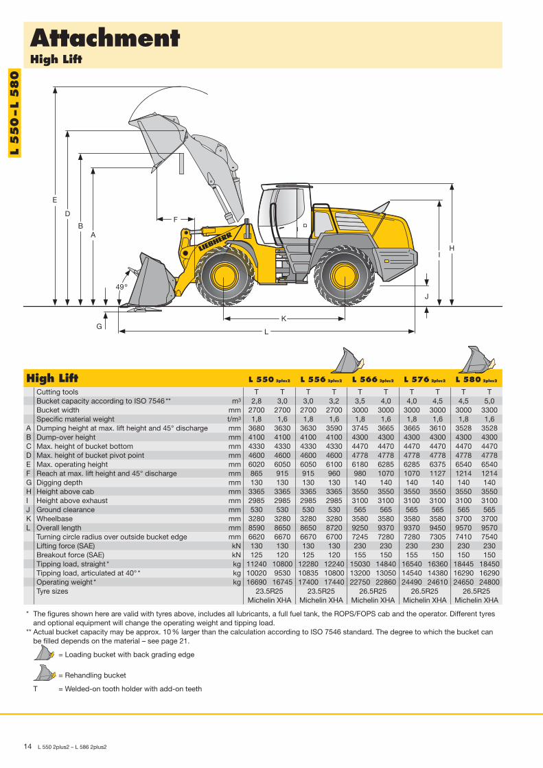
High Lift L 550 2plus2 L 556 2plus2 L 566 2plus2 L 576 2plus2 L 580 2plus2
Cutting toolsBucket capacity according to ISO 7546 ** m3
Bucket width mmSpecific material weight t/m3
A Dumping height at max. lift height and 45° discharge mmB Dump-over height mmC Max. height of bucket bottom mmD Max. height of bucket pivot point mmE Max. operating height mmF Reach at max. lift height and 45° discharge mmG Digging depth mmH Height above cab mmI Height above exhaust mmJ Ground clearance mmK Wheelbase mmL Overall length mm
Turning circle radius over outside bucket edge mmLifting force (SAE) kNBreakout force (SAE) kNTipping load, straight * kgTipping load, articulated at 40° * kgOperating weight * kgTyre sizes
* The figures shown here are valid with tyres above, includes all lubricants, a full fuel tank, the ROPS/FOPS cab and the operator. Different tyresand optional equipment will change the operating weight and tipping load.
** Actual bucket capacity may be approx. 10 % larger than the calculation according to ISO 7546 standard. The degree to which the bucket canbe filled depends on the material – see page 21.
= Loading bucket with back grading edge
= Rehandling bucket
T = Welded-on tooth holder with add-on teeth
T T T T T T T T T T2,8 3,0 3,0 3,2 3,5 4,0 4,0 4,5 4,5 5,0
2700 2700 2700 2700 3000 3000 3000 3000 3000 33001,8 1,6 1,8 1,6 1,8 1,6 1,8 1,6 1,8 1,6
3680 3630 3630 3590 3745 3665 3665 3610 3528 35284100 4100 4100 4100 4300 4300 4300 4300 4300 43004330 4330 4330 4330 4470 4470 4470 4470 4470 44704600 4600 4600 4600 4778 4778 4778 4778 4778 47786020 6050 6050 6100 6180 6285 6285 6375 6540 6540865 915 915 960 980 1070 1070 1127 1214 1214130 130 130 130 140 140 140 140 140 1403365 3365 3365 3365 3550 3550 3550 3550 3550 35502985 2985 2985 2985 3100 3100 3100 3100 3100 3100530 530 530 530 565 565 565 565 565 5653280 3280 3280 3280 3580 3580 3580 3580 3700 37008590 8650 8650 8720 9250 9370 9370 9450 9570 95706620 6670 6670 6700 7245 7280 7280 7305 7410 7540130 130 130 130 230 230 230 230 230 230125 120 125 120 155 150 155 150 150 150
11240 10800 12280 12240 15030 14840 16540 16360 18445 1845010020 9530 10835 10800 13200 13050 14540 14380 16290 1629016690 16745 17400 17440 22750 22860 24490 24610 24650 24800
23.5R25 23.5R25 26.5R25 26.5R25 26.5R25Michelin XHA Michelin XHA Michelin XHA Michelin XHA Michelin XHA
L 550 – L 5
80
AttachmentLight Material Bucket
L 550 2plus2 – L 586 2plus2 15
E
L
F
A
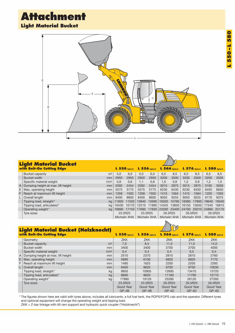
Light Material Bucketwith Bolt-On Cutting Edge L 550 2plus2 L 556 2plus2 L 566 2plus2 L 576 2plus2 L 580 2plus2
Bucket capacity m3
Bucket width mmSpecific material weight t/m3
A Dumping height at max. lift height mmE Max. operating height mmF Reach at maximum lift height mmL Overall length mm
Tipping load, straight * kgTipping load, articulated * kgOperating weight * kgTyre sizes
5,0 6,0 5,0 6,0 6,5 8,5 6,5 8,5 6,5 8,52950 2950 2950 2950 3200 3500 3200 3500 3200 35000,8 0,6 1,1 0,8 1,0 0,8 1,2 0,9 1,2 1,0
2592 2454 2592 2454 3015 2875 3015 2875 3195 30505575 5775 5575 5775 6230 6430 6230 6430 6450 66501358 1502 1358 1502 1415 1564 1415 1564 1205 13558400 8600 8400 8600 9050 9255 9050 9255 9170 937511820 11520 13840 13580 16320 15760 18380 17800 19640 1904010430 10170 12210 11990 14345 13850 16150 15650 17340 1681516990 17150 17690 17830 23290 23400 24700 25010 24860 25170
23.5R25 23.5R25 26.5R25 26.5R25 26.5R25Michelin XHA Michelin XHA Michelin XHA Michelin XHA Michelin XHA
L 550 – L 5
80
Light Material Bucket (Holzknecht)with Bolt-On Cutting Edge L 550 2plus2 L 556 2plus2 L 566 2plus2 L 576 2plus2 L 580 2plus2
GeometryBucket capacity m3
Bucket width mmSpecific material weight t/m3
A Dumping height at max. lift height mmE Max. operating height mmF Reach at maximum lift height mmL Overall length mm
Tipping load, straight * kgTipping load, articulated * kgOperating weight * kgTyre sizes
* The figures shown here are valid with tyres above, includes all lubricants, a full fuel tank, the ROPS/FOPS cab and the operator. Different tyresand optional equipment will change the operating weight and tipping load.ZKK = Z-bar linkage with tilt ram support and hydraulic quick coupler (“Holzknecht”)
ZKK ZKK ZKK ZKK ZKK7,0 8,5 11,0 11,0 14,0
3400 3400 3700 3700 40000,4 0,4 0,4 0,5 0,4
2510 2370 2810 2810 27605890 6100 6820 6820 71701480 1625 2200 2200 22608400 8620 9700 9700 100309850 10905 12695 13410 137208690 9620 11160 11790 1211017980 19120 25280 26120 27260
23.5R25 23.5R25 26.5R25 26.5R25 26.5R25Good Year Good Year Good Year Good Year Good Year
GP-4B GP-4B GP-4D GP-4D GP-4D

AttachmentHigh-Dump Bucket
16 L 550 2plus2 – L 586 2plus2
E
L
FA
High-Dump Bucketwith Bolt-On Cutting Edge L 550 2plus2 L 556 2plus2 L 566 2plus2 L 576 2plus2 L 580 2plus2
Bucket capacity m3
Bucket width mmSpecific material weight t/m3
A Dumping height at max. lift height mmE Max. operating height mmF Reach at maximum lift height mmL Overall length mm
Tipping load, straight * kgTipping load, articulated * kgOperating weight * kgTyre sizes
4,5 5,0 6,5 6,5 6,52700 2700 3200 3200 32000,9 0,9 0,8 1,0 1,0
4560 4730 5320 5320 55406600 6800 7600 7600 78201660 1620 1830 1830 16558920 9050 9660 9660 978011490 11945 13650 15580 1679010130 10540 12000 13270 1482017325 18490 24810 25920 26380
23.5R25 23.5R25 26.5R25 26.5R25 26.5R25Michelin XHA Michelin XHA Michelin XHA Michelin XHA Michelin XHA
L 550 – L 5
80
High-Dump Bucket (Holzknecht)with Bolt-On Cutting Edge L 550 2plus2 L 556 2plus2 L 566 2plus2 L 576 2plus2 L 580 2plus2
GeometryBucket capacity m3
Bucket width mmSpecific material weight t/m3
A Dumping height at max. lift height mmE Max. operating height mmF Reach at maximum lift height mmL Overall length mm
Tipping load, straight * kgTipping load, articulated * kgOperating weight * kgTyre sizes
* The figures shown here are valid with tyres above, includes all lubricants, a full fuel tank, the ROPS/FOPS cab and the operator. Different tyresand optional equipment will change the operating weight and tipping load.ZKK = Z-bar linkage with tilt ram support and hydraulic quick coupler (“Holzknecht”)
ZKK ZKK ZKK ZKK ZKK7,0 8,0 11,0 11,0 13,0
3000 3500 3700 3700 40000,4 0,4 0,4 0,5 0,4
4850 4980 4550 4550 47807300 7350 8280 8280 85901995 1960 2060 2060 20808980 8750 9630 9630 99609220 10290 11540 12340 128308130 9080 10140 10850 1133018480 19615 25580 26520 27780
23.5R25 23.5R25 26.5R25 26.5R25 26.5R25Good Year Good Year Good Year Good Year Good Year
GP-4B GP-4B GP-4D GP-4D GP-4D

AttachmentFork Carrier and Fork
L 550 2plus2 – L 586 2plus2 17
E
F
C
L
A
F max.
F min.
600
G
FEM IV Fork Carrier and Forkwith Quick Change Device L 550 2plus2 L 556 2plus2 L 566 2plus2 L 576 2plus2 L 580 2plus2
A Lifting height at max. reach mmC Max. lifting height mmE Max. operating height mmF Reach at loading position mmF max. Max. reach mmF min. Reach at max. lifting height mmG Fork length mmL Length – basic machine mm
Tipping load, straight * kgTipping load, articulated * kgRecommended payload foruneven ground = 60 % oftipping load, articulated 1) kgRecommended payload forsmooth surfaces = 80 % oftipping load, articulated 1) kgOperating weight * kgTyre sizes
* The figures shown here are valid with tyres above, includes all lubricants, a full fuel tank, the ROPS/FOPS cab and the operator. Different tyresand optional equipment will change the operating weight and tipping load.
1) According to EN 473-3 and ISO 143972) Payload on forks is limited by tilt cylinder
1780 1780 1780 1985 1985 19853680 3680 3680 4130 4130 43504680 4680 4680 5300 5300 55401020 1020 1020 1250 1250 13001655 1655 1655 1960 1960 1970835 835 835 1020 1020 8401500 1200 1500 1800 1800 18007160 7160 7160 7920 7920 81009140 10400 10370 11600 12650 141408065 9180 9150 10200 11050 12280
4550 5490 5490 5885 6630 7500
5800 2) 6500 2) 6500 2) 7845 8840 8840 2)
16395 17040 17080 22715 23530 2428523.5R25 23.5R25 26.5R25 26.5R25 26.5R25
Michelin XHA Michelin XHA Michelin XHA Michelin XHA Michelin XHA
L 550 – L 5
80

18 L 550 2plus2 – L 586 2plus2
AttachmentLog Grapple (Holzknecht)
C
A 45A 20
I
E
Q
F max.
L
K
H
J
F 20
QC 1
F 45
Log Grapple L 550 2plus2 L 556 2plus2 L 566 2plus2 L 576 2plus2 L 580 2plus2
GeometryA20 Discharge height at 20° mmA45 Discharge height at 45° mmC Max. grapple opening in loading position mmC1 Max. grapple opening mmE Max height mmF20 Reach at max. lifting height at 20° discharge mmF45 Reach at max. lifting height at 45° discharge mmF max. Max. outreach mmH Height above cab mmI Manipulation height mmJ Ground clearance mmK Wheelbase mmL Overall length mm
Width over tyres mmQ Grapple diameter m2
Grapple width mmPayload * kgOperating weight * kgTyre sizes
* The figures shown here are valid with tyres above, includes all lubricants, a full fuel tank, the ROPS/FOPS cab and the operator. Different tyresand optional equipment will change the operating weight and tipping load.
** Data with rear tyres filled with waterZKK = Z-bar linkage with tilt ram support and hydraulic quick coupler (“Holzknecht”)
ZKK ZKK ZKK ZKK ZKK3240 3150 3400 3400 36302720 2590 2700 2700 28802270 2035 3000 3000 33702580 2500 3300 3300 36506200 6300 7500 7500 78001700 1875 2340 2340 22301260 1400 1770 1770 16602525 2700 3260 3260 33403365 3365 3580 3580 35804500 4450 5200 5200 5400530 530 565 565 5653280 3280 3580 3580 37008500 8550 9600 9600 99802700 2700 2930 2930 29301,8 2,4 3,1 3,1 3,5
1820 1780 1850 1850 18505900** 6400** 8200** 8650** 9200**18560** 19740** 25980** 26790** 27850**23.5R25 23.5R25 26.5R25 26.5R25 26.5R25
Good Year Good Year Good Year Good Year Good YearGP-4B GP-4B GP-4D GP-4D GP-4D
L 550 – L 5
80

L 550 2plus2 – L 586 2plus2 19
Technical Data
L 586
EngineLiebherr diesel engine ____________ D936L A6
Design ________________________ Liebherr diesel engine, water-cooled, exhaust turbocharged with intercooler
Cylinder inline ________________ 6Combustion process ________ Unit pump (PLD) microprocessor controlledRated output accordingto ISO 9249 __________________ 250 kW at 2000 RPMMax. torque __________________ 1590 Nm at 1500 RPMDisplacement ________________ 10,52 litresBore/Stroke __________________ 122/150 mm
Air cleaner __________________________ Dry type with main and safety element, pre-cleaner,service indicator on LCD display
Electrical systemOperating voltage ____________ 24 VCapacity ______________________ 170 AhAlternator______________________ 28 V/80 AStarter motor ________________ 24 V/6,6 kW
The exhaust emissions are below the limits in stage IIIA / Tier 3.
SteeringDesign ______________________________ “Load-sensing” swash plate type variable flow pump
with pressure cut-off and flow control. Central pivotwith two double-acting, damped steering cylinders
Angle of articulation ______________ 37° (to each side)Emergency steering ______________ Electro-hydraulic emergency steering system
Operator’s CabDesign ______________________________ On elastic bearing on rear section, soundproof
ROPS/FOPS cab. Operator’s door with optional sliding window, 180° opening angle, fold-out windowon right site with opening angle, front windscreenmade of compound safety glass, green tinted asstandard, side windows made of single-pane safetyglass, grey tinted, continuously adjustable steeringcolumn and joystick control as standard, heatablerear windowROPS roll over protection per DIN/ISO 3471/EN 474-3FOPS falling objects protection per DIN/ISO 3449/EN 474-1
Liebherr Operator’s seat __________ 6 way adjustable seat with lap belt, vibration damping and suspension adjustable for the opera -tor’s weight
Cab heating and ventilation ______ Operator’s cab with 4-level air control, cooling waterheating, defroster and air conditioning with electronicvalve control, as well as electronic fresh/recirculatedair control, filter system with pre-filter, fresh air filterand recirculated air filter, easily replaced, air con -ditioning as standard
AttachmentGeometry __________________________ Powerful Z-pattern linkage with tilt cylinder and cast
steel cross-tubeBearings ____________________________ SealedCycle time at nominal load ________ Lifting ________________________________________________ 6,5 s
Dumping ____________________________________________ 3,0 sLowering (empty) __________________________________ 4,0 s
BrakesWear-free service brake __________ Self-locking of the hydrostatic travel drive (acting on
all four wheels) and additional pump-accumulatorbrake system with wet multi-disc brakes (two sepa -rate brake circuits)
Parking brake ______________________ Electro-hydraulically actuated spring-loaded brakesystem on the transmission
The braking system meets the requirements of the EC guidelines 71/320.
Travel DriveStepless hydrostatic travel drive
Design “2plus2” ______________ Swash plate type variable flow pump and two varia-ble axial piston motors in closed loop circuit with oneaxle transfer case. Direction of travel in reversed bychanging the flow-direction of the variable-displace-ment pump
Filtering system ______________ Suction return line filter for closed circuitControl ________________________ By travel and inching pedal. The inching pedal makes
it possible to control the tractive and thrust forcessteplessly at full engine speed. The Liebherr joystickis used to control forward and reverse travel
Travel speed range ________________ Speed range 1 ____________________________ 0 – 8,0 km/hSpeed range 2 and A2 ____________________ 0 – 16,0 km/hSpeed range A3 __________________________ 0 – 35,0 km/hThe quoted speeds apply with the tyres that are standard equipment on the loader
AxlesFour-wheel driveFront axle __________________________ FixedRear axle____________________________ Centre pivot, with 13° oscillating angle to each side
Height of obstacles whichcan be driven over __________ 530 mm
With all four wheels remaining in contact with theground
Differentials ________________________ Automatic limited-slip differentialsReduction gear ____________________ Planetary final drive in wheel hubsTrack width ________________________ 2400 mm with all types of tyres
Noise EmissionISO 6396____________________________ LpA (inside cab) = 69 dB(A)2000/14/EC ________________________ LWA (surround noise) = 107 dB(A)
CapacitiesFuel tank __________________________________________________________________________________ 500 lEngine oil (including filter change) ________________________________________________________ 43 lPump distributor gears ____________________________________________________________________ 7,7 lTransmission “2plus2”____________________________________________________________________ 11,5 lCoolant ______________________________________________________________________________________ 59 lFront axle ____________________________________________________________________________________ 90 lRear axle ____________________________________________________________________________________ 56 lHydraulic tank ____________________________________________________________________________ 180 lHydraulic system, total __________________________________________________________________ 350 lAir condition system R134a ____________________________________________________________ 1250 g
Attachment HydraulicsDesign ______________________________ “Load-sensing” swash plate type variable flow pump
with output and flow control, and pressure cut-off inthe control block
Cooling______________________________ Hydraulic oil cooling using thermostatically controlledfan and oil cooler
Filtering ____________________________ Return line filter in the hydraulic reservoirControl ______________________________ “Liebherr-Joystick” with hydraulic servo controlLift circuit __________________________ Lifting, neutral, lowering
and float positions controlled by Liebherr joystickwith detent
Tilt circuit __________________________ Tilt back, neutral, dumpautomatic bucket positioning
Max. flow __________________________ 410 l/min.Max. pressure ______________________ 330 bar
20 L 550 2plus2 – L 586 2plus2
Dimensions
J
L
K
F
D
E
G
I H
CB
A
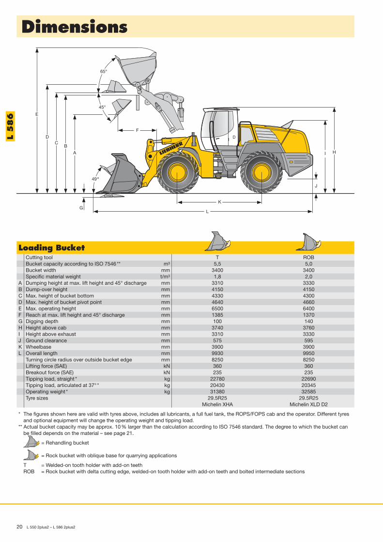
Loading BucketCutting toolBucket capacity according to ISO 7546 ** m3
Bucket width mmSpecific material weight t/m3
A Dumping height at max. lift height and 45° discharge mmB Dump-over height mmC Max. height of bucket bottom mmD Max. height of bucket pivot point mmE Max. operating height mmF Reach at max. lift height and 45° discharge mmG Digging depth mmH Height above cab mmI Height above exhaust mmJ Ground clearance mmK Wheelbase mmL Overall length mm
Turning circle radius over outside bucket edge mmLifting force (SAE) kNBreakout force (SAE) kNTipping load, straight * kgTipping load, articulated at 37° * kgOperating weight * kgTyre sizes
* The figures shown here are valid with tyres above, includes all lubricants, a full fuel tank, the ROPS/FOPS cab and the operator. Different tyresand optional equipment will change the operating weight and tipping load.
** Actual bucket capacity may be approx. 10 % larger than the calculation according to ISO 7546 standard. The degree to which the bucket canbe filled depends on the material – see page 21.
= Rehandling bucket
= Rock bucket with oblique base for quarrying applications
T = Welded-on tooth holder with add-on teethROB = Rock bucket with delta cutting edge, welded-on tooth holder with add-on teeth and bolted intermediate sections
T ROB5,5 5,0
3400 34001,8 2,0
3310 33304150 41504330 43004640 46606500 64001385 1370100 1403740 37603310 3330575 5953900 39009930 99508250 8250360 360235 235
22780 2269020430 2034531380 32585
29.5R25 29.5R25Michelin XHA Michelin XLD D2
L 586

Bulk Material Densities and Bucket Filling Factors
L 550 2plus2 – L 586 2plus2 21
Tipping Load
ISO7546
What is tipping load?Load at centre of gravity of working equip-ment, so that the wheel loader just begins totip over the front axle.This the most unfavourable static-load posi-tion for the wheel loader.Lifting arms horizontal, wheel loader fully articulated at centre pivot.
Pay load.The pay load must not exceed 50 % of thetipping load when articulated.This is equivalent to a static stability-marginfactor of 2,0.
Bucket capacity.The bucket volume is determined from thepay load.
Tipping load, articulated2
Pay load (kg)Specific bulk weight of
material (t/m3)
Pay load =
Bucket capacity =
t/m3 %Gravel, moist 1,9 105
dry 1,6 105wet, 6 – 50 mm 2,0 105dry, 6 – 50 mm 1,7 105crushed stone 1,5 100
Sand, dry 1,5 110moist 1,8 115wet 1,9 110
Gravel and sand, dry 1,7 105wet 2,0 100
Sand and clay 1,6 110
t/m3 %Clay, natural 1,6 110
dry 1,4 110wet 1,65 105
Clay and gravel, dry 1,4 110wet 1,6 100
Earth, dry 1,3 115wet excavated 1,6 110
Topsoil 1,1 110Weathered rock50 % rock, 50 % earth 1,7 100Basalt 1,95 100
t/m3 %Granite 1,8 95Limestone, hard 1,65 95
soft 1,55 100Sandstone 1,6 100Slate 1,75 100Bauxite 1,4 100Gypsum, broken 1,8 100Coke 0,5 110Slag, broken 1,8 100Coal 1,1 110
TyresSize and Change of Width over tyres Change in vertical
tread code operating weight dimensions Usekg mm mm
L 550 2plus2
Bridgestone 23.5R25 VMT L3 + 156 2650 + 30 GravelBridgestone 23.5R25 VSDL L5 + 912 2660 + 65 Stone, RecyclingGoodyear 20.5R25 RT-3B L3 – 592 2660 – 85 GravelGoodyear 20.5R25 GP-2B L2 – 644 2650 – 75 Sand, GravelGoodyear 23.5R25 RT-3B L3 + 124 2660 + 20 GravelGoodyear 23.5R25 GP-2B L2 – 44 2650 + 30 Sand, GravelMichelin 20.5R25 XTLA L2 – 612 2650 – 50 Gravel, EarthworksMichelin 20.5R25 XHA L3 – 616 2650 – 40 GravelMichelin 23.5R25 XTLA L2 – 90 2650 – 5 Gravel, EarthworksMichelin 23.5R25 XHA L3 + 0 2650 + 0 GravelMichelin 23.5R25 XLD D2A L5 + 580 2660 + 40 Stone, RecyclingMichelin 23.5R25 X-MINE D2 L5 + 728 2670 + 60 Stone, RecyclingL 556 2plus2
Bridgestone 23.5R25 VMT L3 + 156 2650 + 30 GravelBridgestone 23.5R25 VSDL L5 + 912 2660 + 70 Stone, RecyclingGood Year 23.5R25 GP-2B L2 – 44 2660 + 30 SandGood Year 23.5R25 RL-5K L5 + 760 2670 + 60 Stone, RecyclingGood Year 23.5R25 RT-3B L3 + 122 2660 + 25 GravelMichelin 23.5R25 XHA L3 + 0 2650 + 0 GravelMichelin 23.5R25 XLD D2 L5 + 580 2660 + 35 Stone, Mining spoilMichelin 23.5R25 X-MINE D2 L5 + 728 2670 + 60 Stone, RecyclingL 566 2plus2
Bridgestone 23.5R25 VMT L3 – 392 2970 – 20 GravelBridgestone 23.5R25 VSDL L5 + 364 2970 + 15 Stone, RecyclingGood Year 23.5R25 GP-2B L2 – 592 2970 – 10 Sand, GravelGood Year 23.5R25 RL-5K L5 + 212 2980 + 10 Stone, RecyclingMichelin 23.5R25 X-MINE D2 L5 + 180 2990 + 10 Stone, RecyclingMichelin 23.5R25 XLD D2 L5 + 32 2970 – 15 Stone, Mining spoilL 566 2plus2/L 576 2plus2/L 580 2plus2
Bridgestone 26.5R25 VMT L3 + 168 2970 + 45 GravelBridgestone 26.5R25 VSDL L5 + 1168 2970 + 70 Stone, RecyclingGood Year 26.5R25 GP-2B L2 – 12 2970 + 25 Sand, GravelGood Year 26.5R25 RL-5K L5 + 1020 2980 + 60 Stone, RecyclingGood Year 26.5R25 RT-3B L3 + 380 2960 + 25 GravelMichelin 26.5R25 XHA L3 + 0 2950 + 0 GravelMichelin 26.5R25 XLD D2 L5 + 660 2970 + 40 Stone, Mining spoilMichelin 26.5R25 X-MINE D2 L5 + 1056 2990 + 60 Stone, RecyclingL 586 2plus2
Bridgestone 29.5R25 VMT L3 + 72 3250 + 45 GravelBridgestone 29.5R25 VSDL L5 + 1320 3260 + 65 Stone, ScrapGood Year 29.5R25 GP2B L2 – 80 3250 + 20 Sand, GravelGood Year 29.5R25 RL5K L5 + 1576 3290 + 60 Industry, StoneMichelin 29.5R25 XHA L3 + 0 3250 + 0 GravelMichelin 29.5R25 XLD D2 L5 + 808 3260 + 20 Stone, Mining spoil, RecyclingMichelin 29.5R25 X-Mine D2 L5 + 1132 3280 + 40 Stone, Scrap
Before operating the vehicle with tyre foam filling or tyre protection chains, please discuss this with Liebherr-Werk Bischofshofen.

22 L 550 2plus2 – L 586 2plus2
Environmental protection can help you earn money!
2
5
4
3
115
20
25
30
35n=?
20m
T ~
35
sec.
2,5
m
A
B
The Liebherr Standard Consumption Test –easy to reproduce and practical.Every Liebherr dealer will provide you with this measuring-tank kit freeof charge or, on request, will carry out the standard fuel consumptiontest on your premises. It’s so easy: you simply determine the numberof loading cycles that can be carried out with 5 litres of diesel. Thematerial is taken from pile A and carried over a distance of 20 metresto point B. The time needed for each working cycle should be35 seconds. Discharge at point B should take place from a height of2,5 m. The working cycles continue until the 5 litres of diesel in theexternal measuring tank have been used up. The loader’s fuel con-sumption per operating hour is calculated as follows:
400Number of loading cycles
= consumptionper hour
Values for the Liebherr Wheel LoadersNumbers of Litres/ Litres/working cycles 100 tons hour
L 524 2plus1: 2,0 m3 n = 44 3,2 9,1L 528 2plus1: 2,2 m3 n = 43 2,9 9,3L 538 2plus1: 2,5 m3 n = 36 2,9 11,1L 542 2plus1: 2,7 m3 n = 35 2,7 11,4L 550 2plus2: 3,2 m3 n = 31 2,6 12,9L 556 2plus2: 3,6 m3 n = 27 2,9 14,5L 566 2plus2: 4,0 m3 n = 22 2,9 18,2L 576 2plus2: 4,5 m3 n = 21 2,9 19,1L 580 2plus2: 5,0 m3 n = 20 2,8 20,0L 586 2plus2: 5,5 m3 n = 14 3,2 28,5*
* Equipped with L5 tires and 5,5 m3 HD bucket
The Liebherr Wheel LoadersStereoloader
L 506Stereo L 507Stereo L 508Stereo L 509Stereo L 510Stereo L 514Stereo
Tipping load kg 3231 3501 3824 4225 4581 5680Bucket capacity m3 0,8 0,9 1,0 1,1 1,2 1,5Operating weight kg 5120 5240 5480 6080 6250 8350Engine output kW/HP 42/58 46/63 46/63 54/74 58/79 72/98
Wheel LoaderL 524 2plus1 L 528 2plus1 L 538 2plus1 L 542 2plus1 L 550 2plus2
Tipping load kg 7300 8100 9020 9760 11650Bucket capacity m3 2,0 2,2 2,5 2,7 3,2Operating weight kg 10350 10780 12430 13040 16525Engine output kW/HP 86/117 86/117 105/143 105/143 130/177
Wheel LoaderL 556 2plus2 L 566 2plus2 L 576 2plus2 L 580 2plus2 L 586 2plus2
Tipping load kg 13140 15550 17200 18000 20430Bucket capacity m3 3,6 4,0 4,5 5,0 5,5Operating weight kg 17270 22500 24260 24580 31380Engine output kW/HP 140/191 190/259 200/272 200/272 250/340
06.08

L 550 2plus2 – L 586 2plus2 23
• = Standard, + = Option, – = not available
Equipment
All illustrations and data may differ from standard equipment. Subject to change without notice.
Basic MachineLiebherr-2plus2-travel gear • • • • • •Ride control • • • • • •Automatic travel mode • • • • • •20 km/h speed limiting + + + + + +Electronical theft protection + + + + + +Creep speed/Cruise control • • • • • •Electronic crowding force control • • • • • •Combined inching-braking system • • • • • •Multi-disc limited slip differentials in both axles • • • • • •Air cleaner system with pre-filter • • • • • •Fluff trap for radiator + + + + + +Reversible fan drive + + + + + +Emergency steering system • • • • • •Liebherr bio degredable hydraulic oil + + + + + +Headlights • • • • • •Two tail lights • • • • • •Two working area lights at rear • • • • • •Battery master switch • • • • • •Pre-heat system for cold starting • • • • • •Towing hitch • • • • • •Lockable doors, service flap and engine hood • • • • • •Toolbox with toolkit • • • • • •Back-up alarm + + + + + +Exhaust pipe – stainless steel + + + + + +Noise suppression package “101” + + + + + –Automatic central lubrication system + + + + + •Road ballast – – – + – –Fuel particle filter + + + + + +
Operator’s CabSoundproof ROPS/FOPS cab with tinted safety glass frontwindscreen, heatable rear window
• • • • • •
Joystick steering + + + + + +2in1 steering system – changeable + + + + + –Hot water heater with defroster and recirculated-air system • • • • • •Adjustable steering column • • • • • •Height-adjustable steering column + + + + + +Liebherr joystick control – adjustable • • • • • •Air conditioning system • • • • • •Liebherr operator’s seat – adjustable in 6 ways • • • • • •Air sprung operator’s seat + + + + + +Air sprung operator’s seat with seat heating + + + + + +Xenon working lights front + + + + + +Four working area lights at front • • • • • •Two or four working area lights rear + + + + + +Windscreen guard + + + + + +Sliding window + + + + + +Floor mat • • • • • •Wash/wipe system for windscreen and rear window • • • • • •Interior rear-view mirror • • • • • •Sun visor • • • • • •Cup holder • • • • • •Clothes hook • • • • • •Storage box with cooling function + + + + + +Storage box • • • • • •Lockable storage compartment • • • • • •Plug 12 V • • • • • •Ashtray • • • • • •Horn • • • • • •Provision for radio including loudspeaker + + + + + +Radio set + + + + + +Operator’s package • • • • • •Dust filter system + + + + + +Protective ventilation system + + + + + +Amber beacon + + + + + +Fire extinguisher 2 kg + + + + + +
Warning Lights for:Engine oil pressure • • • • • •Engine overheat • • • • • •Parking brake • • • • • •Hydraulic oil temperature • • • • • •Air cleaner blockage • • • • • •Battery charge • • • • • •Flow through emergency steering system • • • • • •
Instruments for:Diesel engine pre-heat • • • • • •Engine oil temperature • • • • • •Fuel reserve • • • • • •Timer for hours of operation • • • • • •Speedometer • • • • • •Travel speed ranges and gear selected • • • • • •
Audible Warnings for:Engine oil pressure • • • • • •Engine overheat • • • • • •Overheat of hydraulic fluid • • • • • •Emergency steering system • • • • • •
Function Keys for:Speed range selection • • • • • •Air conditioning • • • • • •Hazard warning flashers • • • • • •Parking brake • • • • • •Electronic tractive force adaptation • • • • • •Creep speed • • • • • •Ride control • • • • • •Automatic bucket positioner • • • • • •Hoist kick-out + + + + + +Additional hydraulics • • • • • •Float position • • • • • •Headlights • • • • • •Working lights front • • • • • •Working lights rear • • • • • •Road travel • • • • • •Wash/wipe system for rear window • • • • • •Amber beacon • • • • • •Mode switch • • • • • •Blower • • • • • •Heater • • • • • •
EquipmentZ-bar linkage • • • • • •Z-bar linkage “High Lift” + + + + + +Industrial Z-bar linkage + + + + + –Hydraulic servo control of working hydraulics • • • • • •Automatic bucket positioner – adjustable • • • • • •Automatic hoist kick out – adjustable + + + + + +Float position • • • • • •Loading buckets with and without teeth, or bolt-on cutting edge + + + + + +High-dump bucket + + + + + +Light material bucket + + + + + +Fork carrier and lift forks + + + + + +Hydraulic quick-change device + + + + + +3rd hydraulic control circuit + + + + + +3rd and 4th hydraulic control circuits + + + + + +Comfort control + + + + + +Country-specific versions + + + + + + 55
0-58
6 02
.07
550 2
plus
2
556 2
plus
2
566 2
plus
2
576 2
plus
2
580 2
plus
2
586 2
plus
2
550 2
plus
2
556 2
plus
2
566 2
plus
2
576 2
plus
2
580 2
plus
2
586 2
plus
2
550 2
plus
2
556 2
plus
2
566 2
plus
2
576 2
plus
2
580 2
plus
2
586 2
plus
2
550 2
plus
2
556 2
plus
2
566 2
plus
2
576 2
plus
2
580 2
plus
2
586 2
plus
2
550 2
plus
2
556 2
plus
2
566 2
plus
2
576 2
plus
2
580 2
plus
2
586 2
plus
2
550 2
plus
2
556 2
plus
2
566 2
plus
2
576 2
plus
2
580 2
plus
2
586 2
plus
2
550 2
plus
2
556 2
plus
2
566 2
plus
2
576 2
plus
2
580 2
plus
2
586 2
plus
2
Forward – reverse travel • • • • • •Forward travel • • • • • •Reverse travel • • • • • •Rev. counter • • • • • •Clock • • • • • •Flashing turn indicators • • • • • •High-beam headlights • • • • • •Diagnosis system • • • • • •
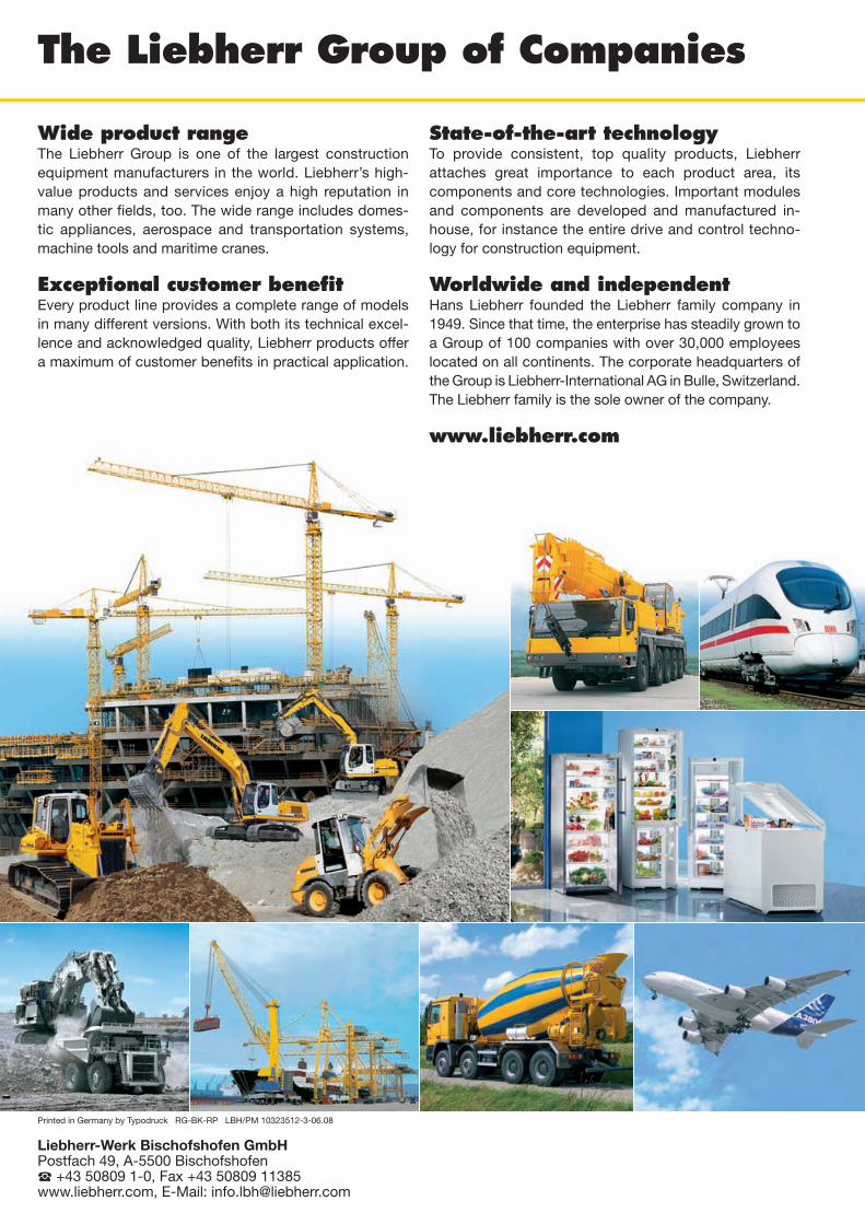
The Liebherr Group of Companies
Wide product rangeThe Liebherr Group is one of the largest constructionequipment manufacturers in the world. Liebherr’s high-value products and services enjoy a high reputation inmany other fields, too. The wide range includes domes -tic appliances, aerospace and transportation systems,machine tools and maritime cranes.
Exceptional customer benefitEvery product line provides a complete range of modelsin many different versions. With both its technical excel -lence and acknowledged quality, Liebherr products offera maximum of customer benefits in practical application.
State-of-the-art technologyTo provide consistent, top quality products, Liebherr attaches great importance to each product area, its components and core technologies. Important modulesand components are developed and manu factured in-house, for instance the entire drive and control techno -logy for construction equipment.
Worldwide and independentHans Liebherr founded the Liebherr family company in1949. Since that time, the enterprise has steadily grown toa Group of 100 companies with over 30,000 employees located on all continents. The corporate headquarters ofthe Group is Liebherr-International AG in Bulle, Switzerland.The Liebherr family is the sole owner of the com pany.
www.liebherr.com
Liebherr-Werk Bischofshofen GmbHPostfach 49, A-5500 Bischofshofen� +43 50809 1-0, Fax +43 50809 11385www.liebherr.com, E-Mail: [email protected]
Printed in Germany by Typodruck RG-BK-RP LBH/PM 10323512-3-06.08


![INDEX [] LG-1550 LIEBHERR LTM 1500 LIEBHERR LTM-1400 LIEBHERR LTM-1225 LIEBHERR LTM-1220 LIEBHERR ... Cranes_over100tons.pdf](https://img.pdfslide.us/doc/110x75/5b07232e7f8b9ae9628e08fa/index-lg-1550-liebherr-ltm-1500-liebherr-ltm-1400-liebherr-ltm-1225-liebherr.jpg)