Embed Size (px)
Citation preview
GENERAL CATALOGUE
WHEEL GEARS

Chapter page1. Introduction
1.1 Presentation1.2 Consulting the catalogue1.3 Safety1.4 Guarantee regulations1.5 General instructions1.6 Technical information1.7 Reproduction and copyright1.8 Revisions1.9 How to read the catalogue code
2. Product Designation2.1 Product Identification
3. General Index of Technical Symbols4. Technical Characteristics
4.1 Output torque4.2 Maximum output torque4.3 Equivalent torque in output4.4 Transmission ratio4.5 Maximum input speed4.6 Rotation direction4.7 Efficiency4.8 Operating temperature4.9 Radial load and Axial load4.10 Maximum draining pressure4.11 Brakes at inlet4.12 Brakes at outlet4.13 Materials
5. Selection5.1 Selection of the wheel gear
5.1.1 Determining the MAX torque5.1.2 Determining the resistant torque during the work cycle5.1.3 Determining the steering torque for tracked vehicles5.1.4 Determining the radial loads5.1.5 Determining the axial loads
5.2 Determining the reduction ratio5.3 Verifying the life of bearings5.4 Wheel gears selection charts
6. Information Request Form7. Lubrication8. Supply Conditions
8.1 Packing8.2 Transport8.3 Receiving8.4 Storing
9. Assembly9.1 General rules9.2 Installation instructions9.3 Commissioning the brakes
9.3.1 Commissioning the positive show brakes9.3.2 Commissioning the negative multiple-disc brakes
10. Checking10.1 First start-up checks10.2 Idle test without load
11. Disengagement12. Maintenance
12.1 Ordinary maintenance12.2 Oil change12.3 Servicing the brakes12.4 Extraordinary maintenance
13. Troubleshooting14. Technical Data Sheets15. Flanging for motor to SAEJ 744C16. Motors Connection
16.1 RRTD and RRWD Series16.2 RRM Series
17. Negative brake connection18. Input side accessories
2
3 4
56 7
810
111213
1415
16
192157
64
171718
596358
65
1TABLE OF CONTENTS

1.1 PRESENTATIONThis brochure illustrates the range of wheel gears designed for translating tracked operating machines and self-propelled tyredvehicles.Continuous research and innovative design have allowed Reggiana Riduttori to create a complete range of wheel gears to satisfy agreat variety of applications.The range of products illustrated is divided mainly into two types:
- Wheel gears for FULL-TRACKED vehicles identified with the initials RRTD- Wheel gears for TYRED vehicles identified with the initials RRWD and RRM.
An internal negative brake can be mounted on the RRTD and RRWD series.A positive shoe brake can be mounted on the RRM series. If you wish to mount a negative brake on this series it has to be on theoutside of the wheel, between motor and input shaft.The high performance and compact size plus the highest reliability, make the Reggiana Riduttori product one of the most qualifiedat industrial level.
1.2 Consulting the catalogueConsultation of this catalogue is facilitated by the main index on the first page, which helps in finding specific subjects.
1.3 Safety
� ATTENTION: please take note that Reggiana Riduttori products cannot be considered safety devices.
1.4 Guarantee regulationsReggiana Riduttori guarantees its products as specified in the guarantee terms in the general conditions of sale and supply.
1.5 General instructionsUpon delivery of the wheel gear check that it has not suffered damage during transport and that all prescribed accessories are present.The wheel gear must be used in environments and for applications that are in line with the provisions of the project. All improper useof the wheel gear is prohibited. Replacement or alteration of parts of the wheel gear, that have not been authorized by ReggianaRiduttori, can give rise to accident risk, and therefore relieve the constructor from any civil or penal responsibility, and cause thewarranty to lose its effect.
1.6 Technical informationThe technical information contained in this brochure is an indication for the choice of the wheel gear, which will have to be determinedby the plant technician in accordance with the application required. The Reggiana Riduttori technical service is available for anyverification needed.
1.7 Reproduction and copyrightReggiana Riduttori s.r.l. reserves all rights.The reproduction, either partial or entire of this brochure, without prior written authorisation from Reggiana Riduttori s.r.l. is prohibited.
1.8 RevisionsReggiana Riduttori may make either technical or dimensional modifications for improving the product, if they are considerednecessary, without having to give prior notice.You can download the most updated version of the catalogue from our web site http://www.reggianariduttori.com.
To verify that the copy in your possession is the latest version issued, contact the Reggiana Riduttori sales service and through thebrochure code, they shall inform you of the present state of the releases issued.
1.9 How to read the catalogue codeYou will find the catalogue code at the back of the catalogue itself, in the bottom right-hand corner.Below is an example of reading the code.
Example : C310.0700.10.300
C310 = catalogue code0700 = year and printing release10 = language300 = no. of printed catalogues
21. INTRODUCTION

� ATTENTION: All wheel gears of the RRM series are supplied with a universal fitting on the inputshaft (see the motor connections paragraph for the RRM series) meaning they need a coupling kit sothey can be connected to the motor chosen.
� ATTENTION: The wheel gears of the RRMB series differ depending on how the brake cable isinstalled. To see if a wheel gear is left (SX) or right (DX), check on which side the brake cable is, lookingat the gear from the motor side.
RRTD 1700 T 64,2 RF27 OMSS
REDUCTION RATIO:see singleTechnical Sheets
No. STAGES:- = SingleD = DoubleT = Triple
SIZE:see singleTechnical Sheets
TYPE:RRTD =for TRACKED VEHICLERRWD=for TYRED VEHICLE
B
CONFIGURAZIONE FRENO:- = SENZA FRENOB = con FRENO NEGATIVO
BRAKE PERFORMANCE:see singleTechnical Sheets
BRAKE CONFIGURATION:- = WITHOUT BRAKEB = with NEGATIVE BRAKE
RRTD and RRWD series of Wheel Gears
RRM series of Wheel Gears
MOTOR SET-UP:see “Motor Connections”data sheets
32. PRODUCT DESIGNATION

2.1 Product IdentificationAll the wheel gears have a metal identification plate, positioned so that it is easy to access even when the wheel gear has beenmounted.The basic data regarding the production is given on this plate, as shown below:
RRM B 1000 37,5 DX
REDUCTION RATIO:see singleTechnical Sheets
SIZE:see singleTechnical Sheets
TYPE:RRM = for TYRED VEHICLE
Type of product
Ordering identificationcode
Brakingtorque
Wheel gearratio
Progressiveserial number
D
No. STAGES:- = SingleD = Double
BRAKE CONFIGURATION:- = WITHOUT BRAKEB = with POSITIVE BRAKE
BRAKE POSITION:(see note on page 4)
DX = Brake cable exiting from the right *SX = Brake cable exiting from the left ** (only if a positive brake is installed)
TYPE: RRWD1700TB
154F4748M137 RT: 1/76,06BK RF:21 ORD / 501540 N. 1347 / 06
S. POLO D’ENZA - REGGIO E. - ITALY
42. PRODUCT DESIGNATION
Ordernumber

53. GENERAL INDEX OF TECHNICAL SYMBOLS
A daN
� °a m/s2
B daN
C daN
Cr -
Cs -
D daN
E daN
ec -
Fa daN
Faa daN
Fr daN
Frr daN
Fs daN
G kg
g m/s2
h h
� -
i -
K Ns2/m4
Lc m
Lp m
n1 rpm
n1max rpm
n2 rpm
p% %
Pdmax bar
r m
S m2
T1 daNm
T2 daNm
T2eq daNm
T2max daNm
Ta daNm
tav s
Tc °CTr daNm
Ts daNm
V km/h
Ve km/h
z -
Object Unit ofmeasure Description
Rolling resistance
Angle of running plane on the horizontal
Average acceleration
Resistance due to the level gradient
Hook traction force
Rolling resistance coefficient
Average vehicle adhesion coefficient
Aerodynamic resistance
Resistance due to acceleration
Track efficiency (0.85÷ 0.9)
Shear force transmitted by the wheel to the ground at the adhesion limit
Axial load applied to the wheel
Minimum shear force at the wheel needed for running
Radial load applied to the wheel
Axial load due to the steering of the track
Total mass of the vehicle
Acceleration of gravity
Duration in hours
Efficiency
Reduction ratio
Vehicle shape coefficient
Track
Pitch
Wheel gear speed at input
Maximum wheel gear speed at input
Wheel gear speed at output
Exceedable slope (p% = 100 x Tan α)
Maximum draining pressure
Rolling radius
Front surface of the vehicle exposed to the wind
Wheel gear input torque
Wheel gear output torque
Wheel gear equivalent output torque
Maximum wheel gear output torque
Output torque at adhesion limit
Time taken by the vehicle to reach the running speed
Operating temperature
Wheel gear resistant torque
Torque needed for the steering
Speed of the vehicle
Wind vehicle speed ratio
Number of driving wheels

64. TECHNICAL CHARACTERISTICS
4.1 Output torque ( T2 )This is the value of the torque transmitted in continuous operation equalling a theoretical life of 30,000 n2 x h.Value T2 given in the technical data sheets takes into account both bending strength and surface resistance of the gear teeth, usuallymore restrictive.
4.2 Maximum output torque ( T2 max )Represents the maximum output torque value, allowable for short periods or for occasional peaks, without showing permanentdamage to the parts under strain.For continuous or heavy use, contact the Reggiana Riduttori technical service.
4.3 Equivalent output torque ( T2 eq )In applications where the load is variable it is necessary to calculate the “equivalent torque” for an approximate selection of the wheelgear. Proceed by finding the operating cycle dividing the working life of the vehicle by n phases, each one characterised by its ownapplied torque level T2 (speed is considered constant in all phases); then apply the following formula:
This gives us torque T2eq, which should be the same as or less than torque T2 corresponding to the wheel chosen.
T2 eq � T2
To make sure you choose the right wheel gear we suggest you fill in the “Information Request Form” and contact the ReggianaRiduttori Technical Service.
4.4 Transmission ratio ( i )Indicates the actual ratio between input speed n1 and output speed n2 of the wheel gear.
4.5 Maximum input speed ( n1max )Indicates the maximum speed allowable in input for brief periods or during intermittent operation.The input speed of the wheel gear is limited by the tip speed of the gears, by the bearings and by the seals.In the case of a wheel gear fitted with negative brake, we advise not to exceed 1500 rpm in continuous operation, so as not to causesignificant increase of the oil temperature.Should the loading conditions entail long periods with a speed close to n1max or with speeds with peaks exceeding those given in thetable of every single wheel gear, contact the Reggiana Riduttori technical service.
4.6 Rotation directionGenerally, for each wheel gear in this catalogue, the output turns in the opposite direction to the input shaft. An exception to this ruleis wheel gear RRWD270/B where, due to its particular internal working, the output turns in the same direction as the input.
4.7 Efficiency ( � )The efficiency is a non-dimensional number, defined as the ratio between the output power and the input power of the wheel gear.The value of the efficiency limited to the wheel gear only, single stage in speed conditions and average torque is equivalent to0,97 ÷ 0,98.
4.8 Operating temperature ( Tc )When working the temperature of the wheel gear should be between –20°C and +90°C.
4.9 Radial load ( Frr ) and Axial load ( Faa )Each single data sheet gives the allowable radial loads curve for a ISO L10 bearing life of 300,000 n2 x h. This value is limited mainlyby the resistance to fatigue of the bearings in accordance with the ISO281 standard. Purely radial loads have been taken intoconsideration.In the presence of axial loads Faa, please contact the Reggiana Riduttori technical service, which will be able to provide you withmore detailed information on the product required.
T2eq = T16,6 • x1 + T2
6,6 • x2 + .....
6,6
1000
0
Pre
ssu
re (
ba
r)
30
Maximum draining pressure diagram
200 300 400 500 600 700 800 900 1000
Inlet revs (rpm)
25
20
15
10
5
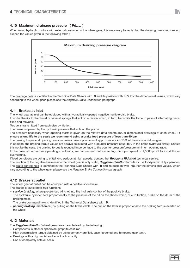
4.10 Maximum drainage pressure ( Pdmax )When using hydraulic motors with external drainage on the wheel gear, it is necessary to verify that the draining pressure does notexceed the values given in the following table :
The drainage hole is identified in the Technical Data Sheets with D and its position with HD. For the dimensional values, which varyaccording to the wheel gear, please see the Negative Brake Connection paragraph.
4.11 Brakes at inletThe wheel gear at inlet can be equipped with a hydraulically opened negative multiple-disc brake.It works thanks to the thrust of several springs that act on a piston which, in turn, transmits the force to pairs of alternating discs,fixed and movable.Torque is transmitted from each disc by friction.The brake is opened by the hydraulic pressure that acts on the piston.The pressure necessary when opening starts is given on the relative data sheets and/or dimensional drawings of each wheel. Toensure a long life to the seals we recommend using a brake feed pressure of less than 40 bar.The braking torque and opening pressure values have a precision of approximately +/- 15% of the nominal values given.In addition, the braking torque values are always calculated with a counter pressure equal to 0 in the brake hydraulic circuit. Shouldthis not be the case, the braking torque is reduced in percentage to the counter pressure/pressure minimum opening ratio.In the case of continuous operating conditions, we recommend not exceeding the input speed of 1,500 rpm-1 to avoid the oiloverheating.If load conditions are going to entail long periods at high speeds, contact the Reggiana Riduttori technical service.The function of the negative brake inside the wheel gear is only static, Reggiana Riduttori forbids its use for dynamic duty operation.The brake control hole is identified in the Technical Data Sheets with B and its position with HB. For the dimensional values, whichvary according to the wheel gear, please see the Negative Brake Connection paragraph.
4.12 Brakes at outletThe wheel gear at outlet can be equipped with a positive shoe brake.The brakes at outlet have two functions:– service braking, where pressurised oil is let into the hydraulic control of the positive brake.
The hydraulic cylinder acts proportionally to the pressure of the oil on the shoes which, due to friction, brake on the drum of thebraking mass.The brake command hole is identified in the Technical Data sheets with B.
– parking braking, mechanical, by pulling on the brake cable. The pull on the lever is proportional to the braking torque exerted onthe wheel.
4.13 MaterialsThe Reggiana Riduttori wheel gears are characterised by the following:– Components in steel or spheroidal graphite cast iron.– High transmissible torque obtained by using correctly profiled, case hardened and tempered gear teeth.– Bearings with a high radial and axial load capacity.– Use of completely safe oil seals.
74. TECHNICAL CHARACTERISTICS

8
5.1 Selection of the wheel gearTo determine the size of the wheel gear suited for the service required, assessment should be made of:
a) The radial and axial loads bearing on the wheel and their positionb) The torque that the wheel has to transmit.
Both the external loads and the torque transmitted vary as the operating conditions of the vehicle vary. It is the designer’s task todefine a work cycle suited to the type of use of the vehicle and, consequently, the loads on the wheel in every phase.The Reggiana Riduttori technical service makes its experience in the sector available to the client, for the definition of the work cycle,and when this has been determined, the torque transmitted by the wheel and the radial and axial loads can be calculated as indicatedin the following paragraphs:
5.1.1 Determining the MAX torqueThe max. torque that can be transmitted by the wheel is that which is obtained when the limit of adhesion between the tyre(or track) and the ground is reached.The torque is calculated by multiplying the radius under load of the wheel by the maximum shear force that it can transmit tothe ground for adhesion:
Ta = Fa · r
5.1.2 Determining the resistant torque during the work cycleTo calculate the resistant torque in a generic phase of the work cycle, it is necessary to determine the resistance to the vehicledriving forwards in that phase and bring it back to the contact point with the ground of each driving wheels. Once defined asFr this tangential force applied to the wheel, the resistant torque is obtained by multiplying Fr by the rolling radius under load:
Tr = Fr · r
The tangential forces Fa and Fr are calculated utilising the following formulas (the units of measure are those given in the tableon page 5):
Shear force transmitted by the wheel tothe ground at the adhesion limit:
Fa = G · g · Cs
10 · z
Minimum shear force at the wheel, needed for driving forwards :
Fr = (A + B + C + D + E)
z
Rolling resistance:
A = G · Cr · g
10
Average acceleration:
a = V
3,6 · tav
Normally the component D is disregarded in the calculation, it assumes an appreciable value only in case of vehicles havinglarge dimensions.
To enable the vehicle to run it is essential that Fr � Fa
Resistance due to the level gradient :
B = G · g · sen�
10
Aerodynamic resistance :
D = K · S · (Ve · 0,2778)2
10
Resistance due to acceleration:
E = G · a
10
5. SELECTION

The following table gives several practical values of the coefficients Cr rolling resistance and Cs adhesion resistance for tyresand tracked vehicles:
5.2 Determining the reduction ratioThe reduction ratio is selected taking into account the characteristics of the motor in consideration of the following relation:
i = T2
= n1
T1 n2
5.3 Verifying the life of bearingsDepending on the loads that bear on the axis of the wheel, with the help of the diagrams given for each wheel gear in the singletechnical data sheets, the load capacity and the life of the bearing can be verified. In the case of high radial loads or axial loads, wesuggest consulting the Reggiana Riduttori technical service.
Road surface
CONCRETE - ASPHALT -MACADAM
COMPACT EARTH
AGRICULTURAL GROUND
0.010÷0.035 0.030÷0.045 0.60÷0.90 0.40÷0.50
0.035÷0.090 0.045÷0.080 0.40÷0.50 0.90÷1
0.035÷0.10 0.05÷0.13 0.45÷0.70 0.80÷1
Rollingresistance coefficient
(Cr)
Average slippingcoefficient of the vehicle
(Cs)
Tyre Track Tyre Track
5.1.3 Determining the steering torque for tracked vehiclesDuring a steering manoeuvre with one of the tracks of a tracked vehicle not moving, the unmoving track slips on the groundwhich means that high traction is required of the other track, in other words, a high torque on the wheel. To have a first ordercalculation of the torque necessary for steering, the following formulas are used:
Fs = (Cs · G · g · Lp)
· 1
4 · Lc · 10 ec
Torque needed for steering:
Ts = Fs · r
5.1.4 Determining the radial loadsThe radial loads acting on the wheel are determined on the basis of the mass of the vehicle, on the distribution of weights andon the slopes (longitudinal and transversal) of the ground on which the work will be done in the various phases of the cycle.
5.1.5 Determining the axial loadsThe axial loads acting on the wheel are determined on the basis of the specific working conditions of the vehicle (transversalslopes, radius and steering speed, etc.). For verifying a wheel gear subject to high axial loads we recommend contacting theReggiana Riduttori technical service.
( )
95. SELECTION

5.4 Wheel gears selection charts0
200
400
600
800
1000
1200
1400
1600
1800
2000
2200
2400
(daNm)
T2T2max
RRTD Series
3200
3400
3600
2600
2800
3000
100
0
100
200
300
400
500
600
700
800
900
1000
1100
1200
1300
1400
1500
1600
1700
(daNm)
T2T2max
270
300
RRWD Series200
500D
600D
800D
1000D
1600D
1700T
1300D
0
100
200
300
400
500
600
700
800
900
1000
1100
1200
1300
1400
1500
1000D
1000
500D
500
200D
200
(daNm)
T2T2max
RRM Series
110
180
220
300
1300D
1700T
2400T
3600T
800D
900D
1000D
105. SELECTION

11The following is a facsimile of the Information request form, to facilitate the choice of the most suitable wheel gear for your machine(authorisation is given to reproduce the form for sending the request). The Reggiana Riduttori technical service will thus be able in avery short time to determine the most suitable product for your application.
6. INFORMATION REQUEST FORM
* Installed power:
Type of document: Technical data sheet for mobile application
Title:
Reserved for commercial technical service: Checked:
Data request form for wheel gears selection
No. of request:
Document referenceClient name:
Machine data–Model:–* Type of vehicle:
Kg* Total weight of vehicle:–
* Distribution of weight (front): Kg* Rear:Kg
–
bar
mm
* Max. Radial load on single wheel: daN
* Radius under load/toothed wheel: mm
cm3* Hydraulic pump displacement:
Operating conditions
–
Min. steering radius: m
* Track: m
m
* Chain pretension: daN(only for tracks)
No. Description of working conditionTimeperc.
[–]
123456
# Positive load (+) when directed towards the outside of the machine.
Comment:
* = Obligatory
* Max brake releasepressure available:
Page 1 of 1
TR-429
Date:
Project ref.:
Address:
Revision index:
E-mail:
Contact:
* Type of work carried out:
* No. of driving wheels:
* Distance (Load-Flanging):
kW
rpm* Hydraulic pump revs:
rpmHydraulic motor revs:
cm3* Hydraulic motor displacement:
barWorking use pressure:
bar* Safety valve calibration:
daNmMax. output torque:
* Planned annual prod. (machines):
* Duration requested: hours
–Type of ground:
Km/h* Maximum linear speed:
%*Vertical slope exceedable:
%* Side slope allowed:
daNForce exerted at hook:
sec* Acceleration (0 - Max. speed):
* Pitch:
Outputtorque
[daNm]
Radialload
[daN]
# Axialload
[daN]
Outputspeed
[min-1]
Distance (+) Distance (-)
Average working cycle

The wheel gears are supplied without any lubricant, which will be added by the user before starting up.Fill the wheel gear as indicated in the MAINTENANCE paragraph.The approximate quantity of oil needed to fill up is given in the technical data sheets of each wheel.It is necessary to carefully check the actual oil level after filling up. Correct lubrication leads to good operating and long life of theoverall wheel gear. It is just as important to choose the correct oil, possibly with an additive, to ensure that the wheel gear lasts a longtime. The operating temperature must not exceed the max. temperature of 90°C. The oil should be changed the first time after50-100 operating hours, and then every 2500 hours or every 12 months. These periods can vary from case to case, depending onthe operating cycle. For special applications, for high speeds or power to transmit please contact the Reggiana Riduttori technicalservice.For the brakes, whether service shoe brakes (positive) or multiple-disc brakes (negative) a MINERAL ISO VG32 hydraulic oil isrecommended.The leading brands of lubricants recommended are given in the following tables, according to working temperatures.
Mineral oil
–10°C / +30°CAmbient temperature
ISO standards, EP grade SAE standard, standardAPI GL5 SAE grade
Synthetic Oil Mineral oil
+10°C / +45°C –20°C / +60°C –20°C / +30°C +10°C / +45°CISO VG 150OIL TYPE ISO VG 220 ISO VG 150-220 SAE 80W/90 SAE 85W/140
BLASIA150AGIP BLASIA220 BLASIA S220 ROTRA MP ROTRA MP
ENERGOL GR XP 150BP - MACH ENERGOL GR XP 220 ENERSYN HTX 220 HYPOGEAR EP HYPOGEAR EP
ALPHA SP 150CASTROL ALPHA SP 220 ALPHASYN PG 150 HYPOY HYPOY
CHEVRON
ELF
ESSO
FINA
IP
KLUBERKLUBER
MOBIL
SHELL
TOTAL
GIRAN 150
MELLANA150
KLUBEROLI GEM1-150
MOBILGEAR 629
OMALA EP150
CARTER EP 150
N.L. GEARCOMPOUND 150
N.L. GEARCOMPOUND 220
UNIVERSAL GEARLUBRICANTE
UNIVERSAL GEARLUBRICANTE
REDUCTELF SP150ELF ORITIS 125 MS
ELF SYNTHERMA P20
GEAR OIL GXPONTONIC MP
GEAR OIL GXPONTONIC MP
REDUCTELF SP220 TRANSELF8 TRANSELF8
SPARTAN EP 150 SPARTAN EP 220 GLYCOLUBE 220
GIRAN 220
MELLANA220 TELESIA OIL 150 PONTIAX HD PONTIAX HD
KLUBEROLI GEM1-320 KLUBERSYNT GH 6-220
MOBILGEAR 630 SHC 630 MOBILUBE HD MOBILUBE HD
OMALA EP220 TIVELA OIL SA SPIRAXHD SPIRAXHD
CARTER EP 220 TRANSMISSION TM TRANSMISSION TM
� ATTENTION: for oil types different from these indicated, contact the Reggiana Riduttori technical service.
127. LUBRICATION
When the wheel gears are delivered, they are ready to be installed, as defined with the client.Except for special requests they are supplied in the following conditions:- Without lubricating oil and completely protected with a film of oil.- Painted with red synthetic anti-oxidation paint (the final painting is at the discretion of the client).- The coupling surfaces are not painted.- Tested- Accurately packed for shipment.
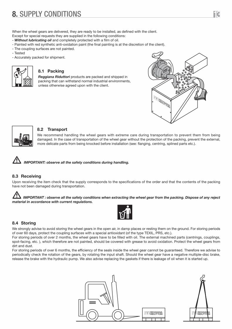
8.1 PackingReggiana Riduttori products are packed and shipped inpacking that can withstand normal industrial environments,unless otherwise agreed upon with the client.
8.2 TransportWe recommend handling the wheel gears with extreme care during transportation to prevent them from beingdamaged. In the case of transportation of the wheel gear without the protection of the packing, prevent the external,more delicate parts from being knocked before installation (see: flanging, centring, splined parts etc.).
� IMPORTANT: observe all the safety conditions during handling.
8.3 ReceivingUpon receiving the item check that the supply corresponds to the specifications of the order and that the contents of the packinghave not been damaged during transportation.
� IMPORTANT : observe all the safety conditions when extracting the wheel gear from the packing. Dispose of any rejectmaterial in accordance with current regulations.
8.4 StoringWe strongly advise to avoid storing the wheel gears in the open air, in damp places or resting them on the ground. For storing periodsof over 60 days, protect the coupling surfaces with a special antioxidant (of the type TEXIL, PRS, etc.).For storing periods of over 2 months, the wheel gears have to be filled with oil. The external machined parts (centrings, couplings,spot-facing, etc. ), which therefore are not painted, should be covered with grease to avoid oxidation. Protect the wheel gears fromdirt and dust.For storing periods of over 6 months, the efficiency of the seals inside the wheel gear cannot be guaranteed. Therefore we advise toperiodically check the rotation of the gears, by rotating the input shaft. Should the wheel gear have a negative multiple-disc brake,release the brake with the hydraulic pump. We also advise replacing the gaskets if there is leakage of oil when it is started up.
138. SUPPLY CONDITIONS
9.1 General rulesThe wheel gears should be installed very carefully.When painting the wheel gears use anti-corrosion paints, protecting the various seals and coupling surfaces with masks or grease.We advise filling up and checking the level of the oil, if possible after installation on the machine. If it is necessary to fill the wheel gearbefore installation, check the level after it has been mounted.
� IMPORTANT: observe all the safety conditions during commissioning.
9.2 Installation instructionsThe structure that the wheel gear is connected to has to be rigid, with a clean coupling surface that is at right angles to the activatedaxis. During the installation phase always make sure that the housing and the splining is carried out correctly.Moreover, the coupling surfaces should be free of dents, to guarantee perfect squareness of the wheel gear/structure coupling.Where the application entails heavy strain, use screws class 10.9 for fastening the wheel gear to the machine structure. Tighten thescrews at the torque advised by the current norms, in accordance with the dimension and the type of material.During the installation of the motor, suitably lubricate the coupling surfaces with a light film of lubricant.Be careful not to damage the O-rings, if they are present.Before tightening the screws make sure that the alignment is correct.Provide protections for motors and connections, where they are exposed to obstacles or irregularity of the ground.When mounting the rims on the wheel gears, make sure that the rim fastening holes fit correctly onto the wheel gear pins so as notto damage the threading.
ATTENTION: for tightening the wheel rims we recommend DIN74361-H-10 nuts.� Apply a tightening torque of the value indicated in the table.
� ATTENTION: check tightness of the screws after the vehicle has been used a short while.
9.3 Commissioning the brakesThe Reggiana Riduttori wheel gears can be supplied with or without brakes.Depending on the type of wheel, the brakes can be positive shoe brakes or negative multiple-disc brakes.Below are the indications for correct brake commissioning.
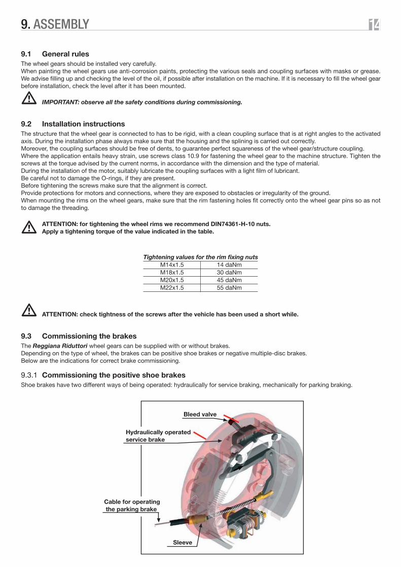
9.3.1 Commissioning the positive shoe brakesShoe brakes have two different ways of being operated: hydraulically for service braking, mechanically for parking braking.
149. ASSEMBLY
Bleed valve
Hydraulically operatedservice brake
Sleeve
Cable for operating the parking brake
Tightening values for the rim fixing nutsM14x1.5 14 daNmM18x1.5 30 daNmM20x1.5 45 daNmM22x1.5 55 daNm

– Service brakeThe commissioning procedure for the shoe brake is the following:– Connect the couplings of the machine’s braking system to the brake control holes of the wheel gears utilising piping and fittings of
a suitable section and that conform to standards.– Put MINERAL oil in the braking system.– Bleed the braking system (eliminate all air from the circuit). This should be done on all wheels on the machine with shoe brakes.
You will need at least two people to bleed the system which has to be done in the following way:– Loosen the bleed valve and press the brake pedal down as far as it will go.– Close the bleed valve without releasing the pedal.– Repeat this until only oil comes from the valve.– At the end check that when pressing the brake pedal it does not go down slowly to the end of its travel.
If the pedal does go down slowly to the end of its travel it means there is some air left in the circuit so bleeding must be repeated.
– Parking brakeConnect the cable to the parking brake control lever.Check the sheath is not throttled anywhere (bent): it would undermine correct system operation.Protect the sheaths from any rough edges in the outside environment.
9.3.2 Commissioning the negative multiple-disc brakesThe commissioning procedure for the negative brake is the following:– Connect the couplings of the hydraulic circuit to the brake control hole on each wheel gear.– Pressurise the hydraulic circuit.– Slightly loosen the oil inlet fitting and wait for the air to come out.– Reclose the fitting when only oil is coming out.
� ATTENTION: check that the release pressure of the negative brake is sufficient to guarantee full opening.Verify the negative brake release data with those on the data sheets of each wheel gear in the catalogue.
� ATTENTION: check that the pressure in the negative brake circuit goes right down to zero when the vehicle has to bebraked. If there is any residual pressure left in the circuit it reduces brake performance.
159. ASSEMBLY

10.1 First start-up checksBefore starting up the machine verify the following:– Check the oil level.– Check the pressure of the braking circuit (if any).
The pressure in the hydraulic braking circuit must be enough to open the negative multiple-disc brake. Working pressure must neverdrop below the minimum negative brake opening pressure. This is to prevent overheating, quick wearing of the discs and unwantedbraking.For the positive brake, the pressure in the hydraulic circuit is proportional to the braking torque.
– Check operation of the positive brake lever (where applied). Pulling the brake cable should guarantee closing of the shoes on thedrum.
– Check tightness of the screws securing the rim to the wheel and those securing the wheel to the machine.
The following table gives the preload and tightening moment for screws with ISO thread and large pitch.Preload has been calculated as being equal to 70% of the minimum yield strength of screw material and attributing an average valueof 0.14 to the friction coefficient.
10.2 Idle test without loadAfter a brief period of operating the vehicle with limited loads, repeat the checks in point 10.1.
Screw
diameter
Max. preload [daN] Max. torque [daNm]
8.8 10.9 12.9 8.8 10.9 12.98G 10K 12K 8G 10K 12K
M4x0.7 394 554 665 0.31 0.43 0.52
M5x0.8 635 895 1070 0.60 0.84 1.01
M6x1 902 1270 1520 1.03 1.46 1.75
M7x1 1300 1820 2180 1.69 2.36 2.83
M8x1.25 1640 2310 2770 2.48 3.49 4.19
M9x1.25 2160 3050 3630 3.67 5.18 6.17
M10x1.5 2600 3660 4380 4.97 7.00 8.37
M12x1.75 3780 5320 6380 8.46 11.90 14.30
M14x2 5160 7250 8700 13.46 18.92 22.70
M16x2 7020 9900 11900 20.40 28.80 34.60
M18x2.5 8600 12100 14500 28.40 40.00 48.00
M20x2.5 11000 15540 18500 39.60 55.60 66.60
M22x2.5 13600 19100 22900 53.00 74.50 90.00
M24x3 15900 22300 26700 70.00 98.00 117.00
M27x3 20600 28900 34700 101.00 142.00 170.00
M30x3.5 28000 39900 46700 150.00 213.00 250.00
1610. CHECKING

The RRTD range of wheel gears does not have the disengagement device fitted as a standard feature.All the RRWD range of wheel gears are fitted with the disengagement device except for some ratios (given in the single data sheets)that do not permit its use.Only the dual stage versions of the RRM range of wheel gears have a disengagement device.
Standard disengagement activation diagram:
Ordinary maintenance should be carried out by qualified personnel in accordance with the methods and times programmed by themanufacturer.The components should be mounted and dismounted only with suitable equipment.Always and only use genuine Reggiana Riduttori spare parts, to guarantee total reliability and safety.
� IMPORTANT: observe all the safety conditions during maintenance jobs.
12.1 Ordinary maintenanceRRTD, RRWD and RRM wheel gears do not require ordinary maintenance, except for changing the oil periodically at the frequenciesindicated in the LUBRICATION paragraph.Only a periodical check of the level of the oil and the state of the seals is necessary.Should an increase of oil be found when the level is being checked, this is an indication that there is a probable blow-by in thehydraulic motor, or in the internal multiple-disc brake (if used). In either case contact the Reggiana Riduttori assistance service.
12.2 Oil changeChange the lubricant oil according to the intervals described in the paragraph “Lubrication”, as follows:– Position the wheel as shown in figure A.– Unscrew and remove the filling up and drainage plugs to facilitate oil drainage.– Wash the inside of the wheel gear with a
specific detergent.– Position the wheel as shown in figure B.– Fill up with oil until the level reaches the
drainage hole.– Close the plugs, replacing the seals
each time.
ON
OFF
ON position reduction ENGAGED
OFF position reduction DISENGAGED
1711. DISENGAGEMENT
12. MAINTENANCE
OILFILLING UP
OIL LEVEL
OILFILLING UP
OIL LEVEL
A: OIL DRAINAGE POSITION B: OIL FILLING UP POSITION

12.3 Servicing the brakesIt is absolutely essential to adjust the brakes after:– Overhauling, mounting or removing the adjustment tool.– Working on the brake that alters its adjustment.– Mounting new drums and shoes.
As the shoe brakes have an automatic play adjustment tool, they need no manual adjustment.Recovery of play is separate in the two driving directions.For the automatic adjustment tool to work there has to be a certain amount of play between shoes and drum.If this certain amount of initial play is less, the adjustment tool will not work until the wear of the shoes brings the play to a steadyvalue.
� ATTENTION: in this case the driver of the vehicle will notice an increase in pedal travel. This is not a malfunction.
If the initial play is too much the adjustment tool starts working and play is stabilised after braking a few times in both directions.
� ATTENTION: excessive play could damage the adjustment tool.
Check that when the handbrake is disengaged, the lever inside the brake returns to the released position so that the shoes on theend closest to the cylinder rest perfectly on the brake shoe holder.
� ATTENTION: if the shoes stay open it means that handbrake travel is not enough. This causes a malfunction of the automatic adjustment tool.
To change worn shoes or brake cylinder, contact the Reggiana Riduttori assistance centre.
� ATTENTION: when braking the first few times, do so very carefully because until the shoes have been run in, theyrespond with a much longer braking action.
For servicing or changing the negative multiple-disc brakes, contact the Reggiana Riduttori assistance centre.
12.4 Extraordinary maintenance“Extraordinary” maintenance is the task of the Reggiana Riduttori “Assistance Service”.Reggiana Riduttori prohibits the opening of the wheel gear for any operation that does not fall within the category of ordinarymaintenance.Reggiana Riduttori shall not assume any responsibility, direct or indirect, to people or objects, deriving from inappropriate use,maintenance or installation of the product.
1812. MAINTENANCE

Should an anomaly occur during operation of the wheel gear consult the following table. If the problem persists, contact the closest"Reggiana Riduttori assistance centre".
ANOMALY POSSIBLE CAUSE SOLUTION
Oil leakage from the seals
1) Hardening of the seals due toprolonged storing
2) Seals damaged or worn
3) Too much lubricant
1) Wheel gear not installed correctly
2) Internal anomaly
3) Bearings badly lubricated or faulty
4) Dented or chipped teeth
1) Lack of pressure in the braking circuit
2) Discs stuck due to the period of stationing
3) Brake seals faulty
1) Residual pressure in the circuit
2) Discs worn
1) Incorrect mounting of motor
2) Brakes blocked
3) Internal anomaly
4) Wheel gear disengaged
1) Either too much or too little oil
2) Unsuitable lubricant
3) Bearings badly lubricated or faulty
4) Multiple-disc brake not opening completely
5) High thermal power
1) No oil in the hydraulic circuit
2) Shoes of the drum brake are worn
3) Air in the brake circuit
1) Not much oil in the hydraulic circuit
2) Air in the brake circuit
1) Clean the area and check for leakage after a few days
2) Contact an Assistance Centre
3) Check oil level
1) Check the fixing
2) Contact an Assistance Centre
3) Contact an Assistance Centre
4) Contact an Assistance Centre
1) Check the brake connection
2) Apply pressure to the brake and turn thewheel by turning the motor on
3) Contact an Assistance Centre
1) Check hydraulic circuit
2) Contact an Assistance Centre
1) Check coupling between motor and wheel gear
2) Check the braking system
3) Contact an Assistance Centre
4) See the DISENGAGE paragraph
1) Check the oil level
2) Check the type and condition of the lubricant
3) Contact an Assistance Centre
4) Check brake opening pressure
5) Contact an Assistance Centre
1) Check for leaks and add oil
2) Change the shoes of the drum brake
3) Bleed the braking circuit
1) Check for leaks and add oil
2) Bleed the braking circuit
Vibrations and/orexcessive noise
The stationing discbrake fails to disengage
Stationing disc brakedoes not block
The wheel gear does not turnwhen the motor is running
Over-heating
Service brake not braking
Brake pedal goes right down
1913. TROUBLESHOOTING


RRTD SERIES
2114. TECHNICAL DATA SHEETS

RRTD 100 - RRTD 100B
TYPE
Max.inputrevs
Mass Oilquantity
Static brakingtorque on
braking at inlet
Openingpressure
(bar)
min. max
RRTD100 5.54 60 100 900 11.5 0.3 – – –
(daNm)
T2 T2maxRatio
.../1 (daNm) (rpm) (kg) (litres) (daNm)
RRTD100B 5.54 60 100 900 12.5 0.2 14 17÷20 150
B
HB
HD
D
HB
B
45°= =
45°M10 n°8
112
72 4013 14
13
M10 n
°8
Ø 17
9
Ø 16
4
Ø 14
4 h8
Ø 14
0
Ø 17
9
Ø 16
4
Ø 14
4 h8
[daN]1500
1000
500
0[mm]
020406080100120
2214. WHEEL GEARS RRTD SERIES

RRTD 100 OMRS - RRTD 100B OMRS
TYPE
Max.inputrevs
Mass Oilquantity
Static brakingtorque on
braking at inlet
Openingpressure
(bar)
min. max
RRTD100 OMRS 5.54 60 100 900 18 0.3 – – –
(daNm)
T2 T2maxRatio
.../1 (daNm) (rpm) (kg) (litres) (daNm)
RRTD100B OMRS 5.54 60 100 900 19 0.2 14 17÷20 150
40000
25
100 300200 600500 min
bar150
125
100
50
75
112
9
40
14
13
P1 P2
F M1 DM2 De
Hydraulic diagram
723 23
129
7
13
72
M10 n°8
111
P1 De P2
Ø140
Ø144
h8
Ø179
10
2323
View from "Y"max.
-1
MAX DRAINAGE PRESSURE
82
"L"
22
Ø155
h8
Ø175
Ø193
"Y"
45°45°
020406080100120[mm]
500
0
1000
[daN]1500
M10 n
°8
Ø164
40
4.2 daNm
3/8"G
P2
1/8"
G
De
P13/8"G
� ATTENTION:For applications on a closed circuit orconnected in series, contact the ReggianaRiduttori technical-commercial service.
TYPE OF MOTOR
Displacement: cm3
Max. speed: min-1
Max. power: kW
Max. pressure variation: bar
Max. flow rate: l/min
Min. speed: min-1
Value “L”: mmOil: ISO VG46 with maximum filtering level 10 µmMaximum hydraulic oil temperature: 80° C
OMRS OMRS80 100
80.3 99.8750 600940 75012.5 13.015.0 15.0175 175200 200225 22560 6075 7510 10
79.2 82.6
cont.discont. 1cont.discont. 1cont.discont. 1peak 2cont.discont. 1
De = External drainageD = DrainageF = Brake ControlM1 = Motor InputM2 = Motor OutputP1 = Input port (branch fed by the pump)P2 = Output port (drainage branch)
NOTE:Always take into account maximum wheel performance whenselecting the motor.
1 Discontinuous duty:– the allowed values are intended for a maximum of 10% of each minute.
2 Peak pressure:– the allowable values can be applied for a maximum of 1% each minute.
2314. WHEEL GEARS RRTD SERIES

RRTD 110 - RRTD 110B
TYPE
Max.inputrevs
Mass Oilquantity
Static brakingtorque on
braking at inlet
Openingpressure
(bar)
min. max
RRTD110 5.54 60 100 900 12.5 0.3 – – –
(daNm)
T2 T2maxRatio
.../1 (daNm) (rpm) (kg) (litres) (daNm)
RRTD110B 5.54 60 100 900 13.5 0.2 14 17÷20 150
B
HB
HD
D
HB
B
112
M10 n
°845° 45°
72 40
15 14
9M10 n°8
Ø 20
0
Ø 18
0
Ø 16
0 h8
Ø 14
3
Ø 15
5 h8
Ø 17
5
Ø 19
3
[daN]3500
[mm]
3000
2500
2000
1500
1000
500
0020406080100120140
2414. WHEEL GEARS RRTD SERIES

RRTD 110 OMRS - RRTD 110B OMRS
TYPE
Max.inputrevs
Mass Oilquantity
Static brakingtorque on
braking at inlet
Openingpressure
(bar)
min. max
RRTD110 OMRS 5.54 60 100 900 19 0.3 – – –
(daNm)
T2 T2maxRatio
.../1 (daNm) (rpm) (kg) (litres) (daNm)
RRTD110B OMRS 5.54 60 100 900 20 0.2 14 17÷20 150
� ATTENTION:For applications on a closed circuit orconnected in series, contact the ReggianaRiduttori technical-commercial service.
TYPE OF MOTOR
Displacement: cm3
Max. speed: min-1
Max. power: kW
Max. pressure variation: bar
Max. flow rate: l/min
Min. speed: min-1
Value “L”: mmOil: ISO VG46 with maximum filtering level 10 µmMaximum hydraulic oil temperature: 80° C
OMRS OMRS OMRS80 100 125
80.3 99.8 125.7750 600 475940 750 60012.5 13.0 12.515.0 15.0 14.5175 175 175200 200 200225 225 22560 60 6075 75 7510 10 9
79.2 82.6 87
cont.discont. 1cont.discont. 1cont.discont. 1peak 2cont.discont. 1
112
9
40
14
15
P1 P2
F M1 DM2 De
Hydraulic diagram
723 23
129
7
72
M10 n°8
111
P1 De P2
Ø143Ø160
h8
Ø200
82
"L"
Ø155
h8
Ø175
Ø193
"Y"
45°45°
M10 n
°8
Ø180
4.2 daNm
9
40000
25
100 300200 600500 min
150
125
100
50
75
10
2323
View from "Y"max
-1
MAX DRAINAGE PRESSURE
22
40
3/8"G
P2
1/8"
GP1
3/8"G
De
140[mm]
[daN]3500300025002000150010005000
120 100 80 60 40 20 0
De = External drainageD = DrainageF = Brake ControlM1 = Motor InputM2 = Motor OutputP1 = Input port (branch fed by the pump)P2 = Output port (drainage branch)
NOTE:Always take into account maximum wheel performance whenselecting the motor.
1 Discontinuous duty:– the allowed values are intended for a maximum of 10% of each minute.
2 Peak pressure:– the allowable values can be applied for a maximum of 1% each minute.
bar
2514. WHEEL GEARS RRTD SERIES

RRTD 180 - RRTD 180B
TYPE
Max.inputrevs
Mass Oilquantity
Static brakingtorque on
braking at inlet
Openingpressure
(bar)
min. max
RRTD180 6.1 80 180 900 19.5 0.2 – – –
(daNm)
T2 T2maxRatio
.../1 (daNm) (rpm) (kg) (litres) (daNm)
RRTD180B 6.1 80 180 900 20.5 0.15 20 14÷18 200
B
HB
HD
D
HB
B
132
M10 n
°845° 45°
92 40
15
15
7.5M10 n°8
Ø 20
0
Ø 18
0
Ø 16
0 h8
Ø 15
9
Ø 15
5 h8
Ø 17
5
Ø 19
3
[daN]
[mm]
3000
2500
2000
1500
1000
500
0020406080100120140
8
2614. WHEEL GEARS RRTD SERIES

RRTD 180 OMRS - RRTD 180B OMRS
TYPE
Max.inputrevs
Mass Oilquantity
Static brakingtorque on
braking at inlet
Openingpressure
(bar)
min. max
RRTD180 OMRS 6.1 80 180 900 26 0.2 – – –
(daNm)
T2 T2maxRatio
.../1 (daNm) (rpm) (kg) (litres) (daNm)
RRTD180B OMRS 6.1 80 180 900 27 0.15 20 14÷18 200
� ATTENTION:For applications on a closed circuit orconnected in series, contact the ReggianaRiduttori technical-commercial service.
TYPE OF MOTOR
Displacement: cm3
Max. speed: min-1
Max. power: kW
Max. pressure variation: bar
Max. flow rate: l/min
Min. speed: min-1
Value “L”: mmOil: ISO VG46 with maximum filtering level 10 µmMaximum hydraulic oil temperature: 80° C
OMRS OMRS OMRS OMRS80 100 125 160
80.3 99.8 125.7 159.6750 600 475 375940 750 600 47012.5 13.0 12.5 1015.0 15.0 14.5 12.5175 175 175 130200 200 200 175225 225 225 22560 60 60 6075 75 75 7510 10 9 7
81.7 85.1 89.5 95.5
cont.discont. 1cont.discont. 1cont.discont. 1peak 2cont.discont. 1
De = External drainageD = DrainageF = Brake ControlM1 = Motor InputM2 = Motor OutputP1 = Input port (branch fed by the pump)P2 = Output port (drainage branch)
NOTE:Always take into account maximum wheel performance whenselecting the motor.
1 Discontinuous duty:– the allowed values are intended for a maximum of 10% of each minute.
2 Peak pressure:– the allowable values can be applied for a maximum of 1% each minute.
P1 P2
F M1 DM2 De
Hydraulic diagram
723 23
129
7
M10 n°8
111
P1 De P2
45°45°
4.2 daNm
132
11.5
40
15
15
7.5
92
Ø159
Ø160
h8
Ø200
84.5
"L"
Ø155
h8
Ø175
Ø193
"Y"
M10 n
°8
Ø180
10
2323
View from "Y"
22
40
3/8"G
P2
1/8"
G
De
P1
3/8"G
020406080100120[mm]
[daN]300025002000150010005000
140
4000 100 300200 600500
bar150
125
100
75
50
25
0max.
min -1
MAX DRAINAGE PRESSURE
2714. WHEEL GEARS RRTD SERIES

RRTD 220 - RRTD 220B
TYPE
Max.inputrevs
Mass Oilquantity
Static brakingtorque on
braking at inlet
Openingpressure
(bar)
min. max
RRTD220 6.1 120 220 900 27 0.2 – – –
(daNm)
T2 T2maxRatio
.../1 (daNm) (rpm) (kg) (litres) (daNm)
RRTD220B 6.1 120 220 900 28 0.15 36 11÷16 200
B
HB
HD
D
HB
B
143.5
M10 n
°8
45° 45°
103.5 40
16
16
10M10 n°8
Ø 22
7
Ø 21
0
Ø 19
0 h8
Ø 18
8
Ø 18
0 h8
Ø 20
0
Ø 23
0
[daN]
3500
[mm]
300025002000150010005000
020406080100120140
8
2814. WHEEL GEARS RRTD SERIES

RRTD 220 OMRS - RRTD 220B OMRS
TYPE
Max.inputrevs
Mass Oilquantity
Static brakingtorque on
braking at inlet
Openingpressure
(bar)
min. max
RRTD220 OMRS 6.1 120 220 900 33.5 0.2 – – –
(daNm)
T2 T2maxRatio
.../1 (daNm) (rpm) (kg) (litres) (daNm)
RRTD220B OMRS 6.1 120 220 900 34.5 0.15 36 11÷16 200
� ATTENTION:For applications on a closed circuit orconnected in series, contact the ReggianaRiduttori technical-commercial service.
TYPE OF MOTOR
Displacement: cm3
Max. speed: min-1
Max. power: kW
Max. pressure variation: bar
Max. flow rate: l/min
Min. speed: min-1
Value “L”: mmOil: ISO VG46 with maximum filtering level 10 µmMaximum hydraulic oil temperature: 80° C
OMRS OMRS OMRS OMRS80 100 125 160
80.3 99.8 125.7 159.6750 600 475 375940 750 600 47012.5 13.0 12.5 1015.0 15.0 14.5 12.5175 175 175 130200 200 200 175225 225 225 22560 60 60 6075 75 75 7510 10 9 7
79.2 82.6 87 93
cont.discont. 1cont.discont. 1cont.discont. 1peak 2cont.discont. 1
De = External drainageD = DrainageF = Brake ControlM1 = Motor InputM2 = Motor OutputP1 = Input port (branch fed by the pump)P2 = Output port (drainage branch)
NOTE:Always take into account maximum wheel performance whenselecting the motor.
1 Discontinuous duty:– the allowed values are intended for a maximum of 10% of each minute.
2 Peak pressure:– the allowable values can be applied for a maximum of 1% each minute.
P1 P2
F M1 DM2 De
Hydraulic diagram
143.5
9
40
16
16
723 23
129
7
103.5
M10 n°8
111
P1 De P2
Ø188
Ø190
h8
Ø227
82
"L"
Ø180
h8
Ø200
Ø230
"Y"
45°45°
M10 n
°8
Ø210
4.2 daNm
10
40000
25
100 300200 600500 min-1
150
125
100
50
7510
2323
View from "Y"
max.
MAX DRAINAGE PRESSURE
22
40
3/8"G
P2
1/8"
GP1
3/8"G
De
140[mm]
[daN]3500300025002000150010005000
120 100 80 60 40 20 0
bar
2914. WHEEL GEARS RRTD SERIES

RRTD 300 - RRTD 300B
TYPE
Max.inputrevs
Mass Oilquantity
Static brakingtorque on
braking at inlet
Openingpressure
(bar)
min. max
RRTD300 6.1 190 300 900 29 0.2 – – –
(daNm)
T2 T2maxRatio
.../1 (daNm) (rpm) (kg) (litres) (daNm)
RRTD300B 6.1 190 300 900 30 0.15 42 14÷16 200
B
HB
HD
D
HB
B
163
M10 n
°8
45° 45°
123 40
14
16
10M10 n°8
Ø 22
7
Ø 21
0
Ø 19
0 h8
Ø 18
8
Ø 18
0 h8
Ø 20
0
Ø 23
0
[daN]8000
[mm]
4000
2000
0020406080100120140
8
6000
160180
3014. WHEEL GEARS RRTD SERIES

232
M16 n
°16
30°
30°
151.5
22
20
72
9M16 n°12
Ø 29
0
Ø 26
0
Ø 22
0 h7
Ø 19
0 f7
Ø 23
0
Ø 26
0
[daN]15000
[mm]
10000
5000
0050100150200250
20= =
RRTD 800D - RRTD 800DB
TYPE
Max.inputrevs
Mass Oilquantity
Static brakingtorque on
braking at inlet
Openingpressure
(bar)
min. max
RRTD800D 22.1 / 26.8 / 30.2 / 41.9 / 53 430 800 3500 59 1.3 – – –
(daNm)
T2 T2maxRatio
.../1 (daNm) (rpm) (kg) (litres) (daNm)
RRTD800DB 22.1 / 26.8 / 30.2 / 41.9 / 53 430 800 3500 60 0.9 14÷33 10÷26 250
B
HB HB
B
3114. WHEEL GEARS RRTD SERIES

M16 n°12
= =
RRTD 900D - RRTD 900DB
TYPE
Max.inputrevs
Mass Oilquantity
Static brakingtorque on
braking at inlet
Openingpressure
(bar)
min. max
RRTD900D 50 / 65 508 1000 3500 – – – – –
(daNm)
T2 T2maxRatio
.../1 (daNm) (rpm) (kg) (litres) (daNm)
RRTD900DB 50 / 65 508 1000 3500 – – 15÷21 14÷23 250
30°
250[mm]
[daN]15000
10000
5000
0
30°B
231
HB
Ø290
Ø260
Ø220
h7 M16
n°1
6
72151.5
202720
20 9
HB
BØ2
30
Ø260
Ø190
f7
200 150 100 50 0
3214. WHEEL GEARS RRTD SERIES

267
M16 n
°16
30°
30° 190 72
M16 n°12
Ø 29
0
Ø 26
0
Ø 22
0 h7
[daN]15000
[mm]050
= =
21
20 25
10
Ø 19
0 f7
Ø 23
0
Ø 26
0
10000
5000
0100150200250
RRTD 1000D - RRTD 1000DB
TYPE
Max.inputrevs
Mass Oilquantity
Static brakingtorque on
braking at inlet
Openingpressure
(bar)
min. max
RRTD1000D 23.7 / 27.2 / 32.3 / 40 490 1000 3500 56 1 – – –
(daNm)
T2 T2maxRatio
.../1 (daNm) (rpm) (kg) (litres) (daNm)
RRTD1000DB 23.7 / 27.2 / 32.3 / 40 490 1000 3500 57 0.8 21÷39 12÷29 250
B
HB HB
B
3314. WHEEL GEARS RRTD SERIES
20°
240[mm]
[daN]
14000
12000
10000
8000
6000
4000
2000
0
20°
B
224
HB
Ø335
Ø305
Ø270
h7 M
16 n
°16
75149
182625
16 8
HB
B
Ø275
Ø300
Ø240
f7
200 160 80 40 0
Ø269
120
M16 n°18
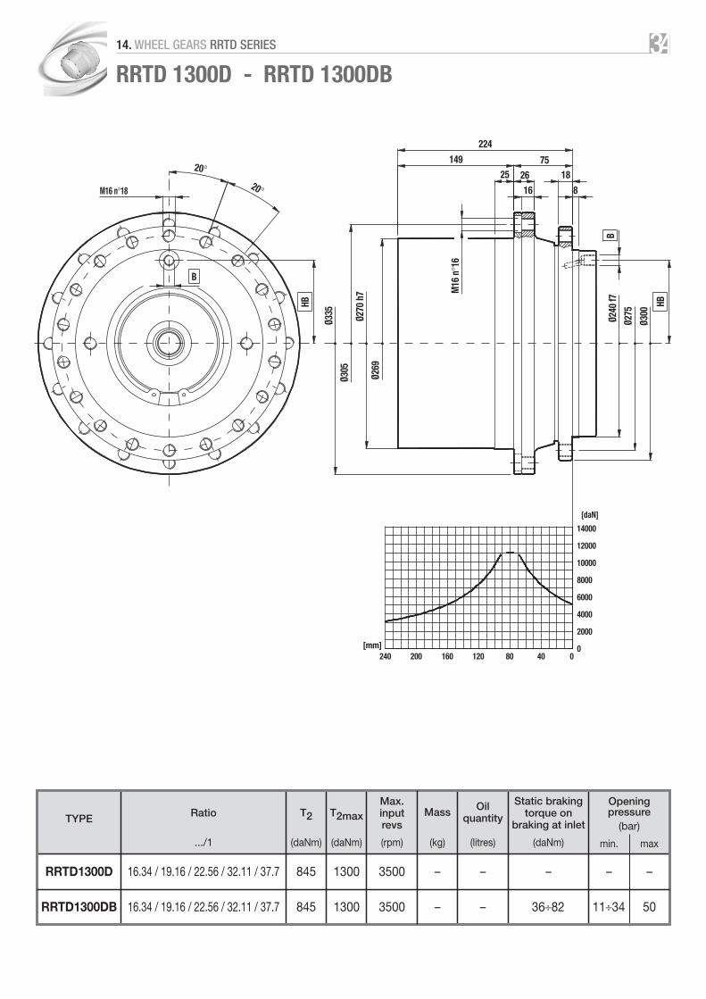
RRTD 1300D - RRTD 1300DB
TYPE
Max.inputrevs
Mass Oilquantity
Static brakingtorque on
braking at inlet
Openingpressure
(bar)
min. max
RRTD1300D 16.34 / 19.16 / 22.56 / 32.11 / 37.7 845 1300 3500 – – – – –
(daNm)
T2 T2maxRatio
.../1 (daNm) (rpm) (kg) (litres) (daNm)
RRTD1300DB 16.34 / 19.16 / 22.56 / 32.11 / 37.7 845 1300 3500 – – 36÷82 11÷34 50
3414. WHEEL GEARS RRTD SERIES

RRTD 1700T - RRTD 1700TB
64.23 / 76.06 / 85.42 / 98.41 / 112.91126.75 / 138.72 / 145.96 / 155.71 / 179.26
TYPE
Max.inputrevs
Mass Oilquantity
Static brakingtorque on
braking at inlet
Openingpressure
(bar)
min. max
RRTD1700T 1100 1700 3500 114 1.5 – – –
(daNm)
T2 T2maxRatio
.../1 (daNm) (rpm) (kg) (litres) (daNm)
RRTD1700TB 1100 1700 3500 115 1.4 7÷25 4÷19 25064.23 / 76.06 / 85.42 / 98.41 / 112.91126.75 / 138.72 / 145.96 / 155.71 / 179.26
B
HB
HB
B
10°
[daN]20000
[mm]0
0
20°
20°
M16 n°18
Ø 37
0
Ø 33
0
Ø 28
0 h7
Ø 26
7
Ø 33
0
Ø 30
0
Ø 27
0 f7
M16
n°1
8
288.5
173.5 115
34
3025
22.5
32°
15000
10000
5000
4080120160200240280
3514. WHEEL GEARS RRTD SERIES

RRTD 2400T - RRTD 2400TB
61.1 / 72.2 / 90.4 / 105118 / 127 / 137 / 166
TYPE
Max.inputrevs
Mass Oilquantity
Static brakingtorque on
braking at inlet
Openingpressure
(bar)
min. max
RRTD2400T 1700 2400 3500 154.5 2.5 – – –
(daNm)
T2 T2maxRatio
.../1 (daNm) (rpm) (kg) (litres) (daNm)
RRTD2400TB 1700 2400 3500 155 1.5 15÷40 11÷32 25061.1 / 72.2 / 90.4 / 105118 / 127 / 137 / 166
B
HB HB
B
[daN]25000
[mm]0
0
Ø 41
0
Ø 38
0
Ø 32
0 h8
Ø 30
7
319
230
37
25
20
20000
15000
5000
4080120160200240280
M20 n°20
18°18°
82
30M16
n°2
0
Ø 24
0 f7
Ø 28
5
Ø 33
0
10000
3614. WHEEL GEARS RRTD SERIES

B
HB
HB
B
[daN]18000
16000
14000
12000
10000
8000
6000
4000
2000
0[mm]0
Ø 38
0
Ø 35
0
Ø 32
0 h8
Ø 31
8.5
300.5
210.5
3725
4080120160200240280
M20 n°16
22.5°
22.5°
90
M16
x1.5
n°2
0
Ø 27
0 f7
Ø 31
0
Ø 35
0
25 24
RRTD 3600T - RRTD 3600TB
67.36 / 79.27 / 99.12115 / 138.8 / 161
TYPE
Max.inputrevs
Mass Oilquantity
Static brakingtorque on
braking at inlet
Openingpressure
(bar)
min. max
RRTD3600T 2490 3600 4500 – – – – –
(daNm)
T2 T2maxRatio
.../1 (daNm) (rpm) (kg) (litres) (daNm)
RRTD3600TB 2490 3600 4500 – – 24÷57 7÷24 5067.36 / 79.27 / 99.12115 / 138.8 / 161
3714. WHEEL GEARS RRTD SERIES


RRWD
3914. TECHNICAL DATA SHEETS
SERIES

RRWD 200 - RRWD 200B
TYPE
Max.inputrevs
Mass Oilquantity
Static brakingtorque on
braking at inlet
Openingpressure
(bar)
min. max
RRWD200 6.1 90 200 900 28 0.4 – – –
(daNm)
T2 T2maxRatio
.../1 (daNm) (rpm) (kg) (litres) (daNm)
RRWD200B 6.1 90 200 900 29 0.3 32 17÷24 250
B
HB HB
HD
D
B
[daN]7000
[mm]0
Ø 18
6
Ø 16
0
Ø 11
0 h8
M14
x1.5
n°5
195
40
155
21
4080120160
45°= =
45°M14 n°8
10 15
Ø 18
0 h8
Ø 20
0
Ø 23
0
6000
5000
4000
3000
2000
1000
0
4014. WHEEL GEARS RRWD SERIES

RRWD 270 - RRWD 270B
TYPE
Max.inputrevs
Mass Oilquantity
Static brakingtorque on
braking at inlet
Openingpressure
(bar)
min. max
RRWD270 5.78 151 250 800 43 0.7 – – –
(daNm)
T2 T2maxRatio
.../1 (daNm) (rpm) (kg) (litres) (daNm)
RRWD270B 5.78 151 250 800 44.5 0.5 38-47 10÷18 50
B HB B
[daN]5000
[mm]0
Ø 22
9
Ø 20
3.2
Ø 15
2.4
h8
208.5
32 10
195
23.5
4000
3000
2000
4080120160200240280
45°= =
45°Ø 15 n°8
95
10°
M14
x1.5
n°8
1017
Ø 19
0
Ø 25
Ø 20
0 h8
Ø 23
0
Ø 26
2
25.5
1000
0
4114. WHEEL GEARS RRWD SERIES

RRWD 300 - RRWD 300B
TYPE
Max.inputrevs
Mass Oilquantity
Static brakingtorque on
braking at inlet
Openingpressure
(bar)
min. max
RRWD300 5.2 130 300 900 29 0.6 – – –
(daNm)
T2 T2maxRatio
.../1 (daNm) (rpm) (kg) (litres) (daNm)
RRWD300B 5.2 130 300 900 30 0.4 49 23÷32 250
HB
HB
B
HD
D
B
[daN]6000
[mm]
Ø 18
6
Ø 16
0
160
30°= =
M14x1.5 n°12
30°
M14
x1.5
n°5
210
Ø 11
0 h8
170
40
10
21
15
Ø 16
0 h8
Ø 18
5
Ø 21
5
5000
4000
3000
2000
1000
0120 80 40 0
4214. WHEEL GEARS RRWD SERIES

RRWD 500D-10” - RRWD 500DB-10”
TYPE
Max.inputrevs
Mass Oilquantity
Static brakingtorque on
braking at inlet
Openingpressure
(bar)
min. max
RRWD500D-10” 15 / 18.2 / 24.2 / 29.3 250 450 3500 49 0.9 – – –
(daNm)
T2 T2maxRatio
.../1 (daNm) (rpm) (kg) (litres) (daNm)
RRWD500DB-10” 15 / 18.2 / 24.2 / 29.3 250 450 3500 50 0.8 14÷32 8÷24 250
HB
HB
B
B
[daN]10000
[mm]
Ø 16
0
Ø 11
0 h8
240
45°= =
M16 n°8
45°
253
38
9
215
25 8
M14
x1.5
n°5
Ø 22
0
Ø 18
0
Ø 19
0 f7
Ø 23
0
Ø 26
0
8000
6000
4000
2000
0200 160 120 80 40 0
4314. WHEEL GEARS RRWD SERIES

RRWD 500D-12” - RRWD 500DB-12”
TYPE
Max.inputrevs
Mass Oilquantity
Static brakingtorque on
braking at inlet
Openingpressure
(bar)
min. max
RRWD500D-12” 15 / 18.2 / 24.2 / 29.3 250 550 3500 49 0.9 – – –
(daNm)
T2 T2maxRatio
.../1 (daNm) (rpm) (kg) (litres) (daNm)
RRWD500DB-12” 15 / 18.2 / 24.2 / 29.3 250 550 3500 50 0.8 14÷32 8÷24 250
HB
HB
B
B
[daN]10000
[mm]240
45°= =
M16 n°8
45°
232
59
Ø 23
5
Ø 19
0 f7
Ø 23
0
Ø 26
0
25
173
12
47.5
8
Ø 20
5
Ø 16
0 h8
8000
6000
4000
2000
0200 160 120 80 40 0
M18
x1.5
n°6
4414. WHEEL GEARS RRWD SERIES

RRWD 600D - RRWD 600DB
17.2 / 20.2 / 25 / 30.238.8 / 45.8 / 56.2
TYPE
Max.inputrevs
Mass Oilquantity
Static brakingtorque on
braking at inlet
Openingpressure
(bar)
min. max
RRWD600D 340 700 3500 45 0.6 – – –
(daNm)
T2 T2maxRatio
.../1 (daNm) (rpm) (kg) (litres) (daNm)
RRWD600DB 340 700 3500 46 0.5 12÷35 8÷32 25017.2 / 20.2 / 25 / 30.238.8 / 45.8 / 56.2
HB
B
[daN]12000
[mm]240
60°= =
60°
220
10
Ø 28
0
17°
5/8”
-11
UNC
n°6
5/8”
-18
UNF
n°9
Ø 24
1.3
Ø 20
0 h7
10
1722
107105
Ø 17
7.8
h8
Ø 20
9.55
Ø 24
0
40
10000
8000
6000
4000
2000
0200 160 120 80 40 0
4514. WHEEL GEARS RRWD SERIES

RRWD 800D - RRWD 800DB
TYPE
Max.inputrevs
Mass Oilquantity
Static brakingtorque on
braking at inlet
Openingpressure
(bar)
min. max
RRWD800D 22.1 / 26.8 / 30.2 / 41.9 / 53 430 800 3500 59 1.3 – – –
(daNm)
T2 T2maxRatio
.../1 (daNm) (rpm) (kg) (litres) (daNm)
RRWD800DB 22.1 / 26.8 / 30.2 / 41.9 / 53 430 800 3500 60 0.9 14÷33 10÷26 250
HB
HB
B
B
[daN]15000
[mm]250
30°= =
M16 n°12
30°
232
151.5
Ø 31
0
Ø 27
5
Ø 22
0 h7
9
2018
38
72
M20
x1.5
n°8
Ø 19
0 f7
20
Ø 23
0
Ø 26
0
10000
5000
0200 150 100 50 0
4614. WHEEL GEARS RRWD SERIES

RRWD 1000D - RRWD 1000DB
TYPE
Max.inputrevs
Mass Oilquantity
Static brakingtorque on
braking at inlet
Openingpressure
(bar)
min. max
RRWD1000D 17.8 650 1100 2000 100 1.6 – – –
(daNm)
T2 T2maxRatio
.../1 (daNm) (rpm) (kg) (litres) (daNm)
RRWD1000DB 17.8 650 1100 2000 102 1.5 59 7÷9 250
HB
HB
B
B
B
[daN]20000
[mm]280
18°= =
323.5
68.5
Ø 31
8
18° 18°
34 34
Ø 28
3
Ø 22
9
M20
x1.5
n°1
2
+0 –0.2
12
20
240
25
50
Ø 23
6 g7
Ø 26
4
Ø 30
0
Ø 17
.5 n
°20
16000
12000
8000
4000
0240 200 160 120 80 40 0
4714. WHEEL GEARS RRWD SERIES
HB
HB
B
B
[daN]14000
12000
10000
8000
6000
4000
2000
0[mm]240
20°
230
140
Ø 37
0
20°
M16 n°18
Ø 33
4.95
Ø 28
0 h8
3/4”
- 16
UNF
n°1
0
1828
90
50
20
Ø 24
0 f7
Ø 27
5
Ø 30
0
200 160 120 80 40 0
Ø 23
4
8
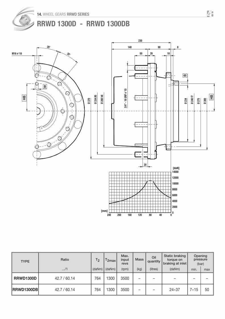
RRWD 1300D - RRWD 1300DB
TYPE
Max.inputrevs
Mass Oilquantity
Static brakingtorque on
braking at inlet
Openingpressure
(bar)
min. max
RRWD1300D 42.7 / 60.14 764 1300 3500 – – – – –
(daNm)
T2 T2maxRatio
.../1 (daNm) (rpm) (kg) (litres) (daNm)
RRWD1300DB 42.7 / 60.14 764 1300 3500 – – 24÷37 7÷15 50
4814. WHEEL GEARS RRWD SERIES

RRWD 1600D - RRWD 1600DB
TYPE
Max.inputrevs
Mass Oilquantity
Static brakingtorque on
braking at inlet
Openingpressure
(bar)
min. max
RRWD1600D 26.8 / 33.3 / 38.2 / 45 / 55.2 800 1600 3000 89 1.9 – – –
(daNm)
T2 T2maxRatio
.../1 (daNm) (rpm) (kg) (litres) (daNm)
RRWD1600DB 26.8 / 33.3 / 38.2 / 45 / 55.2 800 1600 3000 90 1.8 28÷56 15÷39 250
HB
HB
B
B
[daN]20000
[mm]280
10°
M16 n°
18
268
44
Ø 37
5
20°
20°
Ø 33
5
Ø 28
0 h7
Ø 27
0
22.5
Ø 27
0 f7
Ø 30
0
Ø 33
0
M22
x1.5
n°1
0
15
30
115153
15000
10000
5000
0240 200 160 120 80 40 0
32°
4914. WHEEL GEARS RRWD SERIES

32°RRWD 1700T - RRWD 1700TB
64.23 / 76.06 / 85.42 / 98.41 / 112.91126.75 / 138.72 / 145.96 / 155.71 / 179.26
TYPE
Max.inputrevs
Mass Oilquantity
Static brakingtorque on
braking at inlet
Openingpressure
(bar)
min. max
RRWD1700T 1100 1700 3500 114 1.5 – – –
(daNm)
T2 T2maxRatio
.../1 (daNm) (rpm) (kg) (litres) (daNm)
RRWD1700TB 1100 1700 3500 115 1.4 7÷25 4÷19 25064.23 / 76.06 / 85.42 / 98.41 / 112.91126.75 / 138.72 / 145.96 / 155.71 / 179.26
B
HB
HB
B10°
[daN]20000
[mm]0
0
20°
20°
M16 n°18
Ø 37
5
Ø 33
5
Ø 28
0 h7
Ø 26
7
298.5
183.5
M22
x1.5
n°1
0
22.5
3044
115
10
15000
10000
5000
4080120160200240280
Ø 27
0 f7
Ø 30
0
Ø 33
0
5014. WHEEL GEARS RRWD SERIES

RRM
5114. TECHNICAL DATA SHEETS
SERIES

RRM 200 - RRM 200D
TYPEMax. input
revsMass Oil quantity
3.19 202RRM200 3.94 179 280 3500 32 0.7
5.15 131
(daNm)
T2 T2maxRatio
.../1 (daNm) (rpm) (kg) (litres)
11.18 27315.35 21117.18 282
RRM200D 20.27 262 300 3500 35 0.527.55 21728.71 22534.02 218
[daN]4000
[mm]200
45°= =
M14 n°7
45°
248
140
Ø 23
4
45°= =
18
7
ch. 27
Ø 20
5
Ø 16
0 h8
Ø 15
9
Ø 29
Ø 20
M18
x1.5
R16
10
108
24
30
M18
x1.5
n°6
Ø 19
5 f7
Ø 22
5
Ø 25
5
15
3000
2000
1000
0160 120 80 40 0
5214. WHEEL GEARS RRM SERIES

RRMB 200 - RRMB 200D
TYPEMax. input
revsMass Oil quantity
3.19 202RRMB200 3.94 179 280 3500 42 0.7
5.15 131
(daNm)
T2 T2maxRatio
.../1 (daNm) (rpm) (kg) (litres)
11.18 27315.35 21117.18 282
RRMB200D 20.27 262 300 3500 45 0.527.55 21728.71 22534.02 218
B B
[daN]4000
[mm]200
45°= =
M14 n°7
45°
24840
88
Ø 20
5Ø
160
h8Ø
159
M10x1
57
45°= = 98 10°
925800
7415
50
M8x1.25
M12x1.5
ch. 27
18
7
M18
x1.5
Ø 20
Ø 29
R16
M18
x1.5
n°6
103433
117131
14
M10
x1
Ø 19
5 f7
Ø 22
5Ø
255
Ø 29
2 88
15
27°
3000
2000
1000
0160 120 80 40 0
[daNm]250
200
150
100
50
0
[daNm]250
200
150
100
50
0
[daN]0 20 40 60 80 100
[bar]120100806040200
Pull on the lever Hydraulic pressure
Brak
ing
torq
ue
Brak
ing
torq
ue
5314. WHEEL GEARS RRM SERIES

RRM 500 - RRM 500D
[daN]6000
[mm]280
30°= =
M16 n°12
30°
297
10
Ø 30
8
20
8
ch. 30
Ø 34
Ø 24
M20
x1.5
R18
Ø 27
5
Ø 22
0 h8
Ø 20
9
M20
x1.5
n°8
160 137
48
25
Ø 19
5 f7
Ø 22
5
Ø 25
5
18
4000
2000
0240 200 160 120 80 40 0
TYPEMax. input
revsMass Oil quantity
3 390RRM500 3.57 360 400 3500 62 –
4.41 299
(daNm)
T2 T2maxRatio
.../1 (daNm) (rpm) (kg) (litres)
14.11 50319.67 51322.62 44226.43 445RRM500D 650 3500 67 –32.14 44838.24 35941.67 28849.51 343
5414. WHEEL GEARS RRM SERIES

RRMB 500 - RRMB 500D
B
B
20
8
ch. 30
Ø 34
Ø 24M
20x1
.5
R18
[daN]6000
[mm]
30°= =
M16 n°12
30°
297
40
Ø 27
5
Ø 22
0 h8
Ø 20
9
M10x1
[daNm] [daNm]
[daN] [bar]Pull on the lever Hydraulic pressur
Brak
ing
torq
ue
Brak
ing
torq
ue
113
82
108 925
800
5015
74
M12x1.5
M8x1.25
M20
x1.5
n°8
Ø 19
5 f7
150 147
413810
15
M10
x1Ø
225
Ø 25
5
Ø 34
6 113
18
25
4000
2000
004080120160200240280
600500400300200
0
600500400300200
00 100 200 16012080400
100 100
TYPEMax. input
revsMass Oil quantity
3 390RRMB500 3.57 360 400 3500 70 –
4.41 299
(daNm)
T2 T2maxRatio
.../1 (daNm) (rpm) (kg) (litres)
14.11 50319.67 51322.62 44226.43 445RRMB500D 650 3500 75 –32.14 44838.24 35941.67 28849.51 343
5514. WHEEL GEARS RRM SERIES

RRM 1000 - RRM 1000D
TYPEMax. input
revsMass Oil quantity
4 400RRMB1000 4.8 450 850 2000 89 –
6 560
(daNm)
T2 T2maxRatio
.../1 (daNm) (rpm) (kg) (litres)
12.6 110015 1100
19.38 1150RRMB1000D 1400 3500 99 –25.68 115031.2 115037.5 1150
[daN]10000
[mm]320
M16 n°12
330
Ø 33
5
Ø 28
0 h7
Ø 27
9.5
ch. 32
22
8
M22
x1.5
Ø 25
Ø 34
R18
M22
x1.5
n°1
0
8000
4000
2000
0280 240 200 160 120
30°
30°15°
15°
15°15°
15°30°
27
53 10
146184
18
Ø 24
0 f7
Ø 27
5
Ø 31
0
Ø 37
5
6000
80 40 0
5614. WHEEL GEARS RRM SERIES

RRMB 1000 - RRMB 1000D
TYPEMax. input
revsMass Oil quantity
4 400RRMB1000 4.8 450 850 2000 125 –
6 560
(daNm)
T2 T2maxRatio
.../1 (daNm) (rpm) (kg) (litres)
12.6 110015 1100
19.38 1150RRMB1000D 1400 3500 135 –25.68 115031.2 115037.5 1150
B
B
M16 n°12
30°
40M14x1.5
147
ch. 32
228
M22
x1.5
Ø 25
Ø 34
R18
146
30°15°
15°15° 15° 15°
15°
88.5
M14x2
M10x1.5
5°70
979
8401030148
30°
Ø 33
5Ø
280
h7Ø
279.
5
M22
x1.5
n°1
0
Ø 24
0 f7
18
18
330
10
3444
155175
Ø 27
5Ø
310
Ø 45
6 147
M14
x1.5
[daN]10000
[mm]320
8000
6000
4000
2000
0280 240 200 160 120 80 40 0
[daNm]1000
800
600
400
200
0
[daNm]1000
800
600
400
200
0
[daN]100 200 300 400
[bar]16012080400
Pull on the lever Hydraulic pressure
Brak
ing
torq
ue
Brak
ing
torq
ue
0
5714. WHEEL GEARS RRM SERIES

2 HOLES 4 HOLES Splined shaft �=30° ANSI B92.1 Cylindrical shaft
SAE A W Xmin K M S R z DP LS LAmin DSC LS F E
A-A 50.8 6.35 - 82.55 10.3 - - 9 20/40 19 5.1 12.7 19 14.1 3.18
A 82.55 6.35 - 106.4 11.1 - - 9 16/32 23.8 7.6 15.9 23.8 17.6 3.97
B 101.6 9.65 50.8 146 14.3 89.8 14.3 13 16/32 33.3 10.2 22.2 33.3 24.9 6.35
B-B 101.6 9.65 50.8 146 14.3 89.8 14.3 15 16/32 38.1 12.7 25.4 38.1 28.1 6.35
C 127 12.7 63.5 181 17.5 114.5 14.3 14 12/24 47.6 15.2 31.7 47.6 35.2 7.94
C-C 127 12.7 63.5 181 17.5 114.5 14.3 17 12/24 54 17.8 38.1 54 42.3 9.52
D 152.4 12.7 69.8 228.6 20.6 161.6 20.6 13 8/16 66.7 20.3 44.4 66.7 49.3 11.1
E 165.1 15.9 69.8 317.5 27 224.5 20.6 13 8/16 66.7 20.3 44.4 66.7 49.3 11.1
F 177.8 15.9 69.8 350 27 247.5 27 15 8/16 79.4 25.4 - - - -
5815. FLANGING FOR MOTORS TO SAEJ 744C
LS
7.87
LS
7.87
LAmin
6.35
W
E
ØA
1.52
min
6.35
W
ØXm
in
ØA
1.52
min ØD
SC
ØXm
in F
S
ØR n°4
S
K
ØM n
°2

RRTD and RRWD SeriesØM
ØAd
x HM
G
ØE
RRTD
RRWD
PAM MOTOR ØA ØE ØM G d HM01 S-D OMSU 3 DP 12/24 z12 75 104 46 M10 n°4 105÷11902 S-D OMP-OMR 1” SAE 6B 82.55 106.4 55.3 M12 n°2 141÷15703 S-D OMRS B25x22 DIN 5482 100 120 64 M8 n°8 70.2÷8404 S-D OMSS DP 12/24 z12 100 125 27 M10 n°4 124÷14505 S-D OMTS DP 12/24 z16 125 160 46 M12 n°4 146÷191
06 S-D LC/KC 25-45 DP 16/32 z15 135 115.8 125.1
07 S-D 51C060 W30x2x30x14x9g DIN 5480 160 200 127.2 M16 n°2 174.308 S-D 51C080 W40x2x30x18x9g DIN 5480 190 224 155.4 M20 n°2 174.409 S-D 90K55 FM DP 12/24 z14 160 200 130.8 M16 n°2 146.810 Rexroth A2FE 23-28-32 W30x2x30x14x9g DIN 5480 135 160 123.8 M12 n°2 11411 Rexroth A2FE 45-56 W30x2x30x14x9g DIN 5480 160 200 127.3 M16 n°2 133÷14612 Rexroth A2FE 80-90 W40x2x30x18x9g DIN 5480 190 224 155 M20 n°2 15713 Rexroth A6VE 28 W30x2x30x14x9g DIN 5480 135 160 124 M12 n°2 15214 Rexroth A6VE 55 W30x2x30x14x9g DIN 5480 160 200 127 M16 n°2 19215 Rexroth A6VE 80 W40x2x30x18x9g DIN 5480 190 224 155.5 M20 n°2 19816 Rexroth A10FE 23-28 DP 16/32 z13 135 160 115.1 M12 n°2 104.717 Rexroth A10FE 37-45 DP 16/32 z15 135 160 127 M12 n°2 11218 Rexroth A10FM 23-28 DP 16/32 z13 101.6 146 41 1/2”-13 UNC n°2 178.819 Rexroth A10VE 28 DP 16/32 z13 135 160 114.8 M12 n°2 14320 Rexroth A10VE 45 DP 16/32 z15 135 160 127 M12 n°2 12421 Rexroth A10VE 63 DP 12/24 z14 160 200 139.5 M16 n°2 15422 Rexroth A10VM 28 DP 16/32 z13 101.6 146 41 1/2”-13 UNC n°2 18923 Rexroth A10VM 45 DP 16/32 z15 101.6 146 45.9 M14 n°2 219.5
24 Parker F11 14-19 DP 16/32 z13 101.6 146 41 158÷181
25 Parker F12 30 W30x2x30x14x9g DIN 5480 135 160 124 M12 n°2 127
26 Parker F12 30 2B DP 16/32 z13 101.6 146 41 189.5
27 Parker F12 30 4B DP 16/32 z13 101.6 127 41 189.5
28 Parker F12 40-60 W30x2x30x14x9g DIN 5480 160 200 127.3 M16 n°2 133÷14629 Parker F12 80 W40x2x30x18x9g DIN 5480 190 224 155.5 M20 n°2 15730 Parker V12 60 W30x2x30x14x9g DIN 5480 160 200 133 M16 n°2 21331 Parker V12 80 W40x2x30x18x9g DIN 5480 190 224 156.5 M20 n°2 205.532 SAE B 4B Z13 DP 16/32 z13 101.6 127 41 M12 n°4 -33 SAE B 4B Z15 DP 16/32 z15 101.6 127 46 M12 n°4 -34 SAE B 2B Z13 DP 16/32 z13 101.6 146 41 M14 n°2 -35 SAE B 2B Z15 DP 16/32 z15 101.6 146 46 M14 n°2 -36 SAE C 2B Z21 DP 16/32 z21 127 181 57 M16 n°2 -37 SAE C 2B Z23 DP 16/32 z23 127 181 57 M16 n°2 -38 SAE B 4B Z13 DP 16/32 z13 101.6 127 41 1/2”-13 UNC n°4 -39 SAE B 2B Z13 DP 16/32 z13 101.6 146 41 1/2”-13 UNC n°2 -
160*155
M12 n°2*7/16”-14 UNC n°2
M14 n°2*1/2”-13 UNC n°2
M14 n°2*1/2”-13 UNC n°2
M12 n°4*1/2”-13 UNC n°4
5916. MOTORS CONNECTION

RRTD and RRWD Series
01 5 5 31 31 31
02 5 5 27
03 9 9 11.5 9
04 31 31 31 15 22 20
05
06 37 40 69 22 20
07 30 28 20 20
08 53
09 30
10 37 40 22
11 30 28 20 20
12 53
13 37 40 22
14 30 28 20 20
15 53
16 40 22
17 37 69 22 20
18 47
19 40 22
20 37 69 22 20
21 45
22 47
23 31 15
24 31 15 *47
25 37 40 22
26 31 15 *47
27 31 *47
28 30 28 20 20
29 53
30 28 20 20
31 53
32 31
33 31
34 31 15
35 31 15
36
37
38 47
39 47
The value in the boxes represents value X of the drawing and indicates the existence of the motor coupling.
RRTD100 110 180 220 300 800D 900D 1000D 1300D 1700T 2400T 3600T
PAM
6016. MOTORS CONNECTION

RRTD and RRWD Series
01 31 31
02 29 29 17
03
04 31 28 31 22
05 40
06 *24 37 23 22
07 30 23 28
08
09 30
10 37 23 22
11 30 23 28
12
13 37 23 22
14 30 23 28
15
16 23 22
17 37 23 22
18 49 47
19 23 22
20 37 23 22
21 45
22 49 47
23 28 31
24 28 *49 31 *47
25 37 23 22
26 28 *49 31 *47
27 28 *49 31 *47
28 30 23 28
29
30 23 28
31
32 28 31
33 28 31
34 28 31
35 28 31
36 96
37 96
38 49 47
39 49 47
The value in the boxes represents value X of the drawing and indicates the existence of the motor coupling.
RRWD200 270 300 500D 600D 800D 1000D 1300D 1600D 1700T
PAM
6116. MOTORS CONNECTION
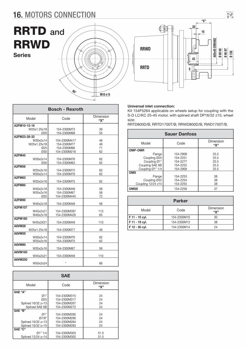
RRTD and
RRWDSeries A0
5x45
DIN
5482
“X”
10
6
43
Ø 60
h8
Ø 95
H7
Ø 15
0RRWD
RRTD
20
M10 n°660°
Universal inlet connection:Kit 154F5264 applicable on wheels setup for coupling with theS-D LC/KC 25-45 motor, with splined shaft DP16/32 z15; wheelsize:RRTD800D/B; RRTD1700T/B; RRWD800D/B; RWD1700T/B.
Bosch - Rexroth
A2FM10-12-16W25x1.25x18 154-2300M73 39
Ø20 154-2300M68 55A2FM23-28-32
W30x2x14 154-2300M417 46W25x1.25x18 154-2300M77 46
Ø25 154-2300M66 71Ø30 154-2300M216 62
A2FM45W30x2x14 154-2300M76 62
Ø30 154-2300M63 62A2FM56
W35x2x16 154-2300M75 62W30x2x14 154-2300M76 62
A2FM63W35x2x16 154-2300M75 62
A2FM80W40x2x18 154-2300M48 56W35x2x16 154-2300M67 56
Ø35 154-2300M445 72A2FM90
W40x2x18 154-2300M48 56A2FM107
W45x2x21 154-2300M397 113W40x2x18 154-2300M426 65
A2FM160W45x2X21 154-2300M49 110
A6VM28W25x1.25x18 154-2300M77 46
A6VM55W30x2x14 154-2300M76 62W35x2x16 154-2300M75 62
A6VM80W35x2x16 154-2300M67 56
A6VM160W45x2x21 154-2300M49 110
A6VM250W50x2x24 * 66
DimensionModel Code “X”
SAE
SAE “A”Ø1” 154-2300M315 24Ø25 154-2300M317 24
Splined 16/32 z=13 154-2300M267 24Splined SAE 6B 154-2300M272 24
SAE “B”Ø1” 154-2300M285 24
Ø7/8” 154-2300M290 24Splined 16/32 z=13 154-2300M284 24Splined 16/32 z=15 154-2300M283 24
SAE “C”Ø1” 1/4 154-2300M303 31.5
Splined 12/24 z=14 154-2300M302 31.5
DimensionModel Code “X”
Sauer Danfoss
OMP-OMRFlange 154-2908 25.5
Coupling Ø25 154-2251 25.5Coupling Ø1” 154-2277 25.5
Coupling SAE 6B 154-2252 25.5Coupling Ø1” 1/4 154-2909 25.5
OMSFlange 154-2253 38
Coupling Ø32 154-2254 38Coupling 12/24 z14 154-2255 38
OMSS 154-2256 37
DimensionModel Code “X”
Parker
F 11 - 10 cyl. 154-2300M10 30
F 11 - 19 cyl. 154-2300M13 38
F 12 - 30 cyl. 154-2300M14 24
DimensionModel Code “X”
6216. MOTORS CONNECTION

RRM Series
= =
RRM
A05x
45 D
IN54
82
M10 n°6
60°
“X”
10
5
18
41
Ø 60
g6
Ø 95
H7
Ø 15
0
Bosch - Rexroth
A2FM10-12-16W25x1.25x18 154-2300M73 39
Ø20 154-2300M68 55A2FM23-28-32
W30x2x14 154-2300M417 46W25x1.25x18 154-2300M77 46
Ø25 154-2300M66 71Ø30 154-2300M216 62
A2FM45W30x2x14 154-2300M76 62
Ø30 154-2300M63 62A2FM56
W35x2x16 154-2300M75 62W30x2x14 154-2300M76 62
A2FM63W35x2x16 154-2300M75 62
A2FM80W40x2x18 154-2300M48 56W35x2x16 154-2300M67 56
Ø35 154-2300M445 72A2FM90
W40x2x18 154-2300M48 56A2FM107
W45x2x21 154-2300M397 113W40x2x18 154-2300M426 65
A2FM160W45x2X21 154-2300M49 110
A6VM28W25x1.25x18 154-2300M77 46
A6VM55W30x2x14 154-2300M76 62W35x2x16 154-2300M75 62
A6VM80W35x2x16 154-2300M67 56
A6VM160W45x2x21 154-2300M49 110
A6VM250W50x2x24 * 66
DimensionModel Code “X”
Sauer Danfoss
OMP-OMRFlange 154-2908 25.5
Coupling Ø25 154-2251 25.5Coupling Ø1” 154-2277 25.5
Coupling SAE 6B 154-2252 25.5Coupling Ø1” 1/4 154-2909 25.5
OMSFlange 154-2253 38
Coupling Ø32 154-2254 38Coupling 12/24 z14 154-2255 38
OMSS 154-2256 37
DimensionModel Code “X”
SAE
SAE “A”Ø1” 154-2300M315 24Ø25 154-2300M317 24
Splined 16/32 z=13 154-2300M267 24Splined SAE 6B 154-2300M272 24
SAE “B”Ø1” 154-2300M285 24
Ø7/8” 154-2300M290 24Splined 16/32 z=13 154-2300M284 24Splined 16/32 z=15 154-2300M283 24
SAE “C”Ø1” 1/4 154-2300M303 31.5
Splined 12/24 z=14 154-2300M302 31.5
DimensionModel Code “X”
Parker
F 11 - 10 cyl. 154-2300M10 30
F 11 - 19 cyl. 154-2300M13 38
F 12 - 30 cyl. 154-2300M14 24
DimensionModel Code “X”
6316. MOTORS CONNECTION

The following table lists the dimensions of the negative multiple-disc brake control hole and of any drainage hole in the wheel gearsof the RRTD and RRWD series.Please refer to the motor coupling column on the Motors Connection Data Sheet (PAM).
WHEEL GEARS PAM B HB D HD
100 01-02 1/8”G 61 1/8”G 61
110 01-02 1/8”G 61 1/8”G 61
180 01-02 1/8”G 68 1/8”G 61
220 01-04 1/8”G 81 3/8”G 67.5
300 01-04 1/8”G 81 3/8”G 67.5
800D All 1/4”G 112.5 – –
900D All 1/4”G 83 – –
1000D All 1/4”G 112.5 – –
1300D All 1/4”G 106.5 – –
1700T All 9/16”-18 SAE J 514 110 – –
2400T All 1/4”G 98 – –
3600T All 1/4”G 116 – –
200 01-02 1/8”G 81 1/8”G 61
270 05 1/8”G 30 – –
300 01-02-04 1/8”G 92.5 1/8”G 61
500D All 1/4”G 112.5 – –
600D06 Ø5 75.3 – –
18-22-24-26-27-38-39 7/16”-20 SAE J 514 88.4 – –
800D All 1/4”G 112.5 – –
1000D 36-37 1/4”G n°2 100 – –
1300D All 1/4”G 106.5 – –
1600D All 9/16”-18 SAE J 514 110 – –
1700T All 9/16”-18 SAE J 514 110 – –
RR
TD
RR
WD
6417. NEGATIVE BRAKE CONNECTION

The RRM series of wheels can be connected at input to the following negative multiple-disc brakes.
Oil fill up plug
Oil level plug
Oil level plug
Oil drainage plug 20°
60°
11°
20°
40°
40°21
°
8.4 daNm
88
75
46.5 10
1/4”G n°4
1/4”GB
13
O-Ring 2-043
Ø95
f7
Ø175
B50x
45 D
IN54
82
5.5
41
525.5
15.5 18
Ø150
Ø194
Ø95
H7
Ø60
g6
A50x
45 D
IN54
82M
10 n
°6
M10
n°8
Oil fill up plug
Oil level plug
Oil level plug
Oil drainage plug
O-Ring 2-043
60°= =
M10
n°6
M10
n°6
Ø10.
5 n°
6
Ø175
Ø95
f7
Ø150
B50x
45DI
N548
2
Ø150
A50x
45
Ø60
g6
DIN5
482
Ø95
H7
Ø195
167 daNm
29
36.5
1/4”G n°4
134
11 58 10
29.5
5
6
1/4”GB
13
41
6518. INPUT SIDE ACCESSORIES
Code 154F5889 154F5890 154F5891 154F5892 154F5893 154F5894
RF2/.. 7 14 21 32 43 60
Static torque daNm 6 ÷ 8 13 ÷ 15 20 ÷ 22 31 ÷ 34 41 ÷ 45 57 ÷ 60
Min. opening pressure bar 4 ÷ 5 8 ÷ 9 12 ÷ 13 18 ÷ 20 24 ÷ 26 27 ÷ 32
Max. opening pressure bar 250
Min. oil capacity to open brake bar 7 ÷ 8
Code 154F5977 154F5978 154F5979 154F5980
RF5/.. 65 85 110 130
Static torque daNm 61 ÷ 70 83 ÷ 92 108 ÷ 118 126 ÷ 136
Min. opening pressure bar 13 ÷ 15 18 ÷ 20 23 ÷ 25 27 ÷ 29
Max. opening pressure bar 250
Min. oil capacity to open brake bar 8 ÷ 9

Notes

Notes

The technical information contained in this catalogue is
indicative for the choice of wheel gear, which will have to be
determined by the system engineer in accordance with the
application required.
The Reggiana Riduttori technical service is available for any
verification needed.
Reggiana Riduttori may make either technical or dimensional
modifications for improving the product, if they are considered
necessary, without having to give prior notice.
The reproduction of this catalogue, even partial, without the
specific written authorisation from Reggiana Riduttori s.r.l. is
prohibited.

REGGIANA RIDUTTORI s.r.l. Via Martiri di Marzabotto, 7 - 42020 S. Polo d’Enza (RE) Italy
Tel. +39 0522 259111 • Fax +39 0522.87.43.21e-mail: [email protected] • www.reggianariduttori.com
C310
-070
0-20
-300