Embed Size (px)
Citation preview

M312Wheel Excavator
Cat® 3054 TA Engine 85 kW/114 hpOperating Weight 13 220 to 14 750 kgBucket Capacities 0.24 to 0.86 m3
MaximumReach at Ground Level 9220 mmDigging Depth 6000 mmTravel Speed 34 km/h
®

The Cat M312 wheel excavatorSetting a high standard in mobility, versatility, operator comfort and ease of maintenance.
The 300 Family sleek styling on wheelsBoth the cab and body have smooth,rounded contours with blended-inroading lights for a modern look.The cab interior combines modernstyling with a soft and pleasing colorscheme. The M312 offers everything an operator could expect today in awheel excavator.
A step forward in environmentalconsiderationsThe Caterpillar 3054 TA engine meetsregulatory emissions requirementsworldwide, including the EuropeanUnion Non-Road Mobile MachineryEngine Emission Directive 97/68/EC.The engine has low spectator andoperator sound levels and the hydraulicsystem can be operated with bio-degradable oil as an option. These features make the M312 a friendly machine, which helps protect the environment. pg. 8

Modern electronicsA microprocessor together with modernelectronics register the operator’scommands and manage the engine andpump interface to help maximize fuelefficiency. pg. 6-7
A choice of the best boom and stick match3 booms and 6 different sticks allowyou to choose the best match for eachjob. Computer aided design and stressanalysis of all front-end structures givethe best combination of durability andweight control. pg. 9
State-of-the-art hydraulic systemThe load-sensing hydraulic system with load independent flow distributionoffers exceptional operation control,modulation, and multi-functioncapability. Up to four additionalhydraulic functions can be added formaximum application flexibility. pg. 10
Ground level maintenanceAll daily maintenance points areaccessible from ground level. A centralized greasing port is located on the right foot of the boom. Thisallows the operator to grease the frontlinkage pins from ground level. pg. 10
The cab: a new referencePilot operated joysticks control front-end and swing functions. The tiltablesteering column and the pedal controlsoffer optimal comfort. The control panelinforms the operator of the machinestatus at all times. Large windows offergood visibility while roading andworking in tight quarters. The fullyadjustable seat offers lumbar support.Heater, defroster, and fan keep positivefiltered air (warm, fresh, or cool ifequipped with the air conditioneroption) flowing through the cab at the flip of a switch. pg. 4-5
Cat ‘5 Star Customer Service’Turns your investment into profit, from purchase to resale through:■ Equipment Management Services
for optimum profit■ Maintenance Services for
equipment protection■ Predictive Services for
optimum availability■ Reconditioning Services for
lower repair cost■ Your Caterpillar dealer for
satisfaction and peace of mind pg. 23

Outstanding operator comfortPlenty of room, all-around visibility, and ergonomic layout for convenient operation.
4
Excellent ventilationStrategically located vents circulate forced air,heat, or defrost air for maximum comfort. The two-piece front window has multiplepositions. In rainy weather, the lower frontwindow can be tilted inwards to provide fresh air and the skylight can be opened for additionalventilation. For work in hot weather conditions, an optional air conditioner is available.
Practical controls■ The control panel switches are conveniently
located.■ Warning lights are clearly visible on the upper
portion of the control panel.■ Joysticks require low effort and a short stroke
for maximum control and efficiency.■ Ample space is reserved for the additional
switches and pedals used to activate optionalequipment.
Easy accessConveniently located grab irons and large stepsmounted on the undercarriage allow easy access to the cab.
A quiet cabThe cab is resiliently mounted. Sound suppressionpanels considerably reduce outside noise levels.
A comfortable seatThe suspension seat adjusts to the operator’sweight and offers excellent lumbar support. There are height-adjustable armrests andnumerous seat adjustments.
Outstanding visibilityWide windows help ensure excellent visibility in all directions. This is especially critical whenroading the machine or when working on publicroadways. A parallelogram windshield wiperclears the front window efficiently in rainyweather. Rear visibility is excellent thanks to thesmall engine cover. The standard skylight providesupward visibility.


6
Maestro Mobile electronic systemAn electronic system matching the state-of-the-art hydraulic system designed specifically for wheel excavator applications.
1 Microprocessor
2 Power mode III indicator
3 Hydraulic oil temperature – high
4 Engine coolant temperature – high
5 Hydraulic oil temperature – low
6 Engine speed dial
7 Travel lock switch
8 Automatic engine control (AEC)switch
9 Back-up switch
10 RH console
11 Power mode switch (I/II)
12 Diagnostic tool or laptop-PCrunning Cat Electronic Technician(ET) software
13 Travel pedal switch
14 Travel pedal magnet
15 Brake light pressure switch
16 Main pump PRV
17 Swing pump PRV
18 Pilot manifold
19 Main pump
20 Swing pump
21 Brake light switch
22 Pressure switch – AEC Main pump
23 Pressure switch – AEC Swing pump
24 Engine speed pick-up
25 Governor actuator and feedbacksensor
26 Pressure switch – AEC stickcylinder
27 Pressure switch – AEC boomcylinder
28 One touch idle down button

7
State-of-the-art hydraulic systemClosed center, variable flow, load-sensing plus. A variabledisplacement piston pump powers the boom, stick, bucket,outriggers/dozer, and travel circuit.A gear pump powers the steering system, the brake system,and the pilot control system, and, if equipped, the mediumpressure function.
A dedicated swing pumpA separate dedicated variable displacement piston pump andfixed displacement piston motor power the swing mechanism.This closed hydraulic circuit helps to provide maximum swingperformance and control at all times.
An efficient and expandable hydraulic systemUp to four optional hydraulic valves can be added to the main valve stack for additional hydraulic functions. A medium pressure auxiliary hydraulic circuit is alsoavailable. These features offer almost unlimited auxiliaryhydraulic capability.
Maestro Mobile Control PanelThe right side console, shown on page 6, contains switchesfor the power mode selector, automatic engine control, lights,windshield wiper and washer, and travel speed selector.
Integrated electronic systemA microprocessor monitors and controls all M312 parametersand functions. The microprocessor was designed specificallyfor a wheel excavator to maximize the efficiency of the engineand the hydraulic system.
This Electronic Control System monitors and controls thefollowing functions:
Engine Speed Control Via Potentiometer – The diesel finalcontrol element at the diesel engine is controlled via apotentiometer in the instrument panel. A button on the rightjoystick immediately sets the idle down manually.
Three power mode settings – There are three power modesettings. The operator can choose the best power setting forboth engine and hydraulics, without any loss of hydraulic force.
Mode III – Works only during travel and is automaticallyengaged. It provides maximum speed and drawbar pull.
Mode II – The standard mode, used for normal truck loading,trenching, and hydraulic hammer use.
Mode I – The economy mode, used for lifting, pipe setting,bank forming, grading, slope finishing, and close quarter and precise work. This mode helps ensure minimum fuelconsumption.
Automatic Engine Speed Control – When activated, this devicereduces engine speed to a minimum during periods of inactivity.This reduces noise and saves fuel.
Electronic Underspeed Control – Constant electronicmonitoring assures that the pump output is always matched to diesel engine power. As a result, a nearly constant dieselengine speed can be maintained.
Protective Measures – Maximum power is reduced whenengine temperature is too high or the hydraulic temperature is either too low or too high.
Diagnostic System – System parameters and failureidentification codes can be read by means of a diagnostic tool.
Top Speed Adjustment (optional) – This holds the travel pedal in the maximum position to reduce strain on the operator. The pedal is released by activating the brake.

8
Cat 3054 TA engineAn emission controlled engine offering the latest environmental benefits.
■ Conservative 85 kW rating, high power to displacement ratio of 21.2 kW/liter and low rpmoperation help ensure long life and exceptional reliability.
■ The 3054 TA engine meets theEuropean Union 97/68/EC Non-RoadMobile Machinery Engine EmissionDirective and the current US EPANon-Road Regulation.
■ Four-stroke-cycle design uses longpower strokes for more complete fuelcombustion and efficiency. Accuratefuel metering results in low fuelconsumption.
■ Long-life design includes largebearing surfaces, alloy steel valves,lightweight cam roller followers, andeasily replaceable crankshaft seals.
■ The engine is designed for hightorque rise at medium rpm. This issuited for excavator applications.
■ The engine is longitudinally mountedon the right to make it easier to servethe oil filter, oil filler, oil drain valve,fuel filter, V-belt tightener, anddipstick which are all accessiblefrom ground level.
■ Low engine noise emissionsmake the M312 a real friendlymachine which helps protect the environment: LpA – 72 dB(A); LWA – 99 dB(A)
Dynamically measured according to ISO6396 or 95/27/EC.
Undercarriage, outriggers, dozer blade, axles Undercarriage and axles match: providing maximum flexibility and mobility.
Undercarriage – A strong and long-lifewelded frame structure built with largesections and thinner plates for excellentrigidity. The frame has been FiniteElement Method analyzed. Both thedozer blade and the outriggers feature a pin-on design.
Axles – Heavy duty axles. The frontaxle offers one of the best axleoscillation and steering in the industryfor optimized flexibility and mobility.
Outriggers – Recommended formaximum operation stability when digging and lifting. They can be controlledindividually to level themachine on slopes. Pin-ondesign, including standard outriggerscylinder guards. Can be mounted on the front and/or on the rear.
Dozer Blade – A useful addition forleveling and backfilling or clean-upwork, also used to improve machinestability when digging or lifting. Pin-on design, including standard dozerblade cylinders guard. This can bemounted on the front and/or on the rear.
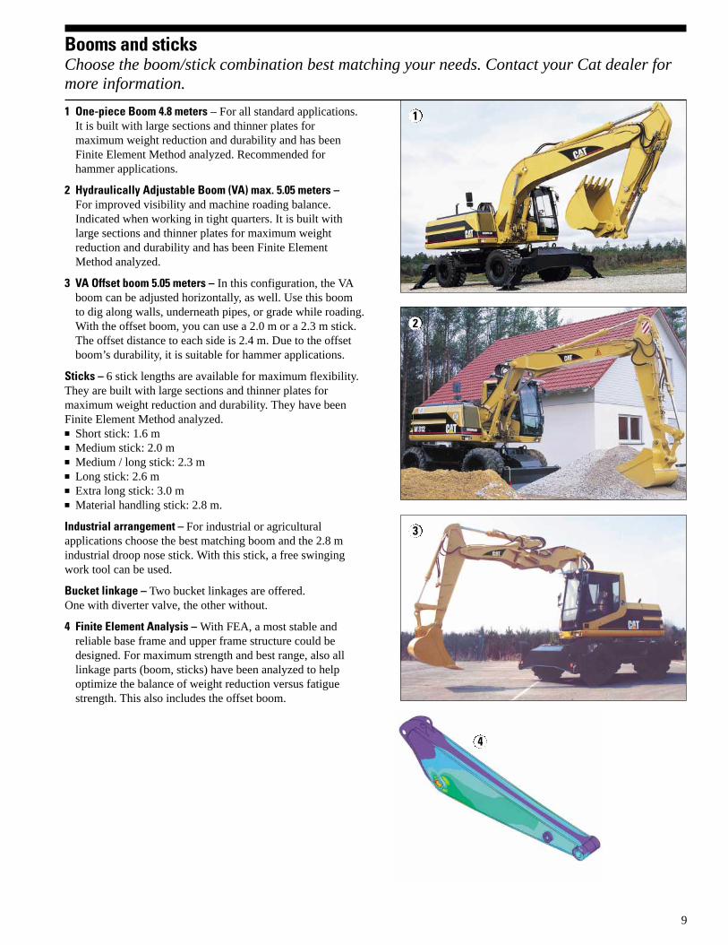
Booms and sticksChoose the boom/stick combination best matching your needs. Contact your Cat dealer formore information.
9
1 One-piece Boom 4.8 meters – For all standard applications.It is built with large sections and thinner plates formaximum weight reduction and durability and has beenFinite Element Method analyzed. Recommended forhammer applications.
2 Hydraulically Adjustable Boom (VA) max. 5.05 meters – For improved visibility and machine roading balance.Indicated when working in tight quarters. It is built withlarge sections and thinner plates for maximum weightreduction and durability and has been Finite ElementMethod analyzed.
3 VA Offset boom 5.05 meters – In this configuration, the VAboom can be adjusted horizontally, as well. Use this boomto dig along walls, underneath pipes, or grade while roading.With the offset boom, you can use a 2.0 m or a 2.3 m stick.The offset distance to each side is 2.4 m. Due to the offsetboom’s durability, it is suitable for hammer applications.
Sticks – 6 stick lengths are available for maximum flexibility.They are built with large sections and thinner plates formaximum weight reduction and durability. They have beenFinite Element Method analyzed.■ Short stick: 1.6 m■ Medium stick: 2.0 m■ Medium / long stick: 2.3 m■ Long stick: 2.6 m■ Extra long stick: 3.0 m■ Material handling stick: 2.8 m.
Industrial arrangement – For industrial or agriculturalapplications choose the best matching boom and the 2.8 mindustrial droop nose stick. With this stick, a free swingingwork tool can be used.
Bucket linkage – Two bucket linkages are offered. One with diverter valve, the other without.
4 Finite Element Analysis – With FEA, a most stable andreliable base frame and upper frame structure could bedesigned. For maximum strength and best range, also alllinkage parts (boom, sticks) have been analyzed to helpoptimize the balance of weight reduction versus fatiguestrength. This also includes the offset boom.
2
3
4
1

10
HydraulicsThe M312 hydraulic system provides more performance and efficiency to your jobs.
Serviceability Simplified service and maintenance features save you time and money.
Efficient and expandable hydraulicsystem – The flow distances betweenhydraulic components are minimized.This helps provide maximum hydraulic efficiency. The load independent flowdistribution together with the separateswing pump helps ensure maximum power at all times.■ Load independent flow distribution
and control system with pressure cut-off. The pump flow is independentlyand proportionally distributed to theflow users. This is a flow-on-demandhydraulic system offering multi-function capability.
■ Optional hydraulic valves can beflanged to the main valve stack formaximum hydraulic flexibility.
Caterpillar XT hoses and couplings –meet the critical flexibility and strengthdemands of wheel excavator applications.O-ring face seal couplings providepositive sealing for reliable and leak-free connections.
Hammer Lines (optional) – Factoryinstalled hammer hydraulic lines areavailable. These lines allow singleacting function for dedicatedproportional hammer foot control formaximum comfort and precision.Optimized hose routing providesexcellent protection and durability.
High Pressure Hydraulic Lines(optional) – Factory installed highpressure lines are available. They aredesigned to function with 2-way hydro-mechanical attachments such as shearsand crushers at maximum workingpressure and flow. Optimized hoserouting provides excellent protectionand durability.
Medium Pressure Hydraulic Lines(optional) – Factory installed mediumpressure lines are available. They aredesigned to function with double-actingrotating devices such as the ditchcleaning bucket tilt and the clamshellrotation. Optimized hose routing providesexcellent protection and durability.
Fast, easy maintenance means improveduptime and better value.
Ground level service points for fuel-water separator, engine oil filter, battery,radiator fluid level, window washer fluid level, fuel filter, engine oil gauge,hydraulic oil level, air cleaner and pilot system filter.
Filters and filter locations make maintenance easier.■ Air cleaner has double layered filter
core and built-in air precleaner for better filtration. No tools requiredto change.
■ Operator is alerted by warning light in cab to need for filter change.
■ Engine oil filter, fuel filter and fuel-water separator are positioned for easier access.
■ Pilot hydraulic system filter keepscontaminates away from the pilotsystem.
Water separator removes water fromfuel even when under pressure and islocated in the engine compartment.
Remote greasing block on the upperframe with two grease points for theswing bearing and one for the front endattachment to deliver grease to hard toreach locations.
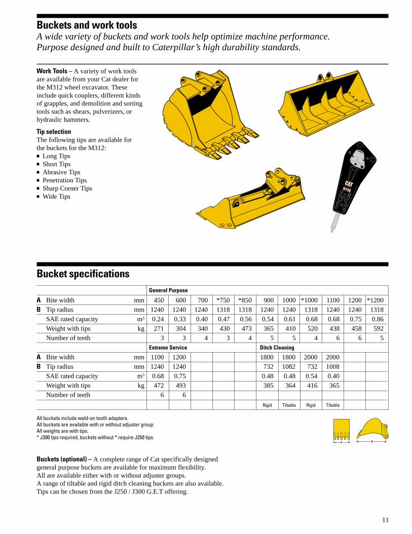
Buckets and work toolsA wide variety of buckets and work tools help optimize machine performance. Purpose designed and built to Caterpillar’s high durability standards.
11
Buckets (optional) – A complete range of Cat specifically designed general purpose buckets are available for maximum flexibility. All are available either with or without adjuster groups.A range of tiltable and rigid ditch cleaning buckets are also available.Tips can be chosen from the J250 / J300 G.E.T offering.
450 600 700 *750 *850 900 1000 *1000 1100 1200 *1200
1240 1240 1240 1318 1318 1240 1240 1318 1240 1240 1318
0.24 0.33 0.40 0.47 0.56 0.54 0.61 0.68 0.68 0.75 0.86
271 304 340 430 473 365 410 520 438 458 592
3 3 4 3 4 5 5 4 6 6 5
A Bite width mm
B Tip radius mm
SAE rated capacity m3
Weight with tips kg
Number of teeth
A Bite width mm
B Tip radius mm
SAE rated capacity m3
Weight with tips kg
Number of teeth
Bucket specifications
➤➤ A ➤➤ B
General Purpose
Extreme Service Ditch Cleaning
RigidRigid Tiltable Tiltable
All buckets include weld-on tooth adapters. All buckets are available with or without adjuster group:All weights are with tips.* J300 tips required, buckets without * require J250 tips.
1100 1200
1240 1240
0.68 0.75
472 493
6 6
1800 1800 2000 2000
732 1082 732 1008
0.48 0.48 0.54 0.40
385 364 416 365
Work Tools – A variety of work toolsare available from your Cat dealer forthe M312 wheel excavator. Theseinclude quick couplers, different kindsof grapples, and demolition and sortingtools such as shears, pulverizers, orhydraulic hammers.
Tip selectionThe following tips are available for the buckets for the M312:■ Long Tips■ Short Tips■ Abrasive Tips■ Penetration Tips■ Sharp Corner Tips■ Wide Tips
H100

12 M312 specifications
BrakesMaintenance free wet-disc servicebrakes on the front and rear axles arestandard.
■ A fully hydraulic service brakesystem. Braking system is suppliedwith hydraulic oil from a separategear pump mounted on the engine.
■ A dual-circuit braking system withindependent front and rear axleservice brake circuits, for increasedsafety.
■ Two separate pre-charged hydraulicaccumulators, one per circuit, for increased safety.
■ A disc brake parking brake located in the transmission housing. Springapplied and hydraulically released.
Ratings at 2000 rpm kW hp
Gross power 88 117
Net power 85 114
The following ratings apply at 2000 rpmwhen tested under the conditions for the specified standard:
Net power kW hp
ISO 9249 85 114
EEC 80/1269 85 114
DimensionsBore 100 mm
Stroke 127 mm
Displacement 4.0 liters
Maximum torque 450 Nm
Torque rise 6.7% at 1600 rpm
■ An emission controlled engine. Meets the 97/68/EC Non-RoadMobile Machinery Engine EmissionDirective and the current US EPANon-Road Regulation.
■ Longitudinal mounting on the right for easy ground access for service/maintenance of: oil filter, oil filler, oil drain valve, fuel filter, V-belttightener, dipstick.
■ An electric 24-volt starting systemwith a 55 amp alternator and two, 12-volt, 100 amp hour CaterpillarMaintenance-Free batteries.
■ An air cleaner, dry type with radialseal primary and secondary element. Easy and rapid to service and replace.
■ Maximum altitude at full power: 2300 meters.
Environmental featuresThe M312 offers a list of features tohelp protect the environment.
■ Low fuel consumption. Compared topower and performance, the M312has a low level of fuel consumption.
■ Biodegradable hydraulic oil. On theM312, you can use a biodegradablehydraulic oil to help protect theenvironment and meet governmentalrequirements in certain countries.
■ The M312 features extremely lowoperator and spectator sound levels.
■ The emission controlled enginecomplies with the 97/68/EC Non-Road-Machinery Engine EmissionDirective.
Emission values g/kWh
Hydrocarbons (HC) below 1.3
Carbon Monoxide (CO) below 5.0
Nitrogen Oxide (NOx) below 9.2
Noise levelsLpA – 72 dB(A); LWA – 99 dB(A)
Dynamically measured according to ISO6396 or 95/27/EC.
Axles and final drivesPlanetary axles with planetary gearreduction final drives located in the axle hubs.
■ All-wheel drive.■ High quality graphite iron axle
housings for maximum strength and durability.
■ Front steering axle oscillates 9°for improved stability andmanoeuvrability in rough terrain.
■ Front axle can be locked fromoperator station in any position ofoscillation for improved workingstability.
Ground clearance (with standard tires) 375 mm
Axle static load capacity 26 000 kg
EngineCaterpillar four-stroke-cycle, four cylinder 3054 TA turbocharged aftercooled diesel engine.
Hydraulic system
Main Hydraulic SystemMaximum flow 190 l/min
Maximum pressure
Implements 330 bar
Travel 330 bar
Optional heavy lift circuit 370 bar
Pilot SystemMaximum flow 15 l/min
Maximum pressure 32 bar

13M312 specifications
Transmission2-gear power-shift transmission. Permanent all wheel drive.
■ Forward, reverse travel and speed arecontrolled by a single foot pedal onthe right side of the steering column.
■ The transmission is protected by adownshift governor to help preventhigh-to-low shift until pre-set slowerground speed is reached.
■ The overspeed valve limits downhilltravel speed in forward and reversegears.
■ An optional two-piece drive shaft withan intermediate bearing to helpmaximize ground clearance isavailable.
■ The transmission is flanged to thedifferential housing of the rear axlefor maximum protection by axle andbase frame, and for better groundclearance.
■ Standard creeper speed.■ Optional travel speed lock for
operator comfort. This locks thetravel pedal for long distancetravelling.
Speeds1st gear, forward/reverse 9 km/h
2nd gear, forward 20/25/30/34 km/h
2nd gear, reverse 20 km/h
Creeper speed (first gear) 3-4 km/h
Creeper speed (second gear) 11-16 km/h
Drawbar pull 70 kN
Gradeability 61%
Service refill capacities
Liters
Fuel Tank 230
Cooling 35
Lubrication
Engine 9
Rear axle housing, differential 11
Front steering axle, differential 7
Final drives, front (each) 2
Final drives, rear (each) 2
Powershift transmission 3
Hydraulic system (including tank) 180
Hydraulic tank 95
SteeringFully hydraulic, powered by a separategear pump mounted on the engine.
■ Maintenance-free steering system.■ Synchronized steering cylinder
integrated in the steering axle housingto help maximize protection.
■ Steering angle of 35° for reducedturning circle and mobility.
■ Optional battery-poweredsupplemental steering system.
Outer turning circle diameter 12.4 m
Vehicle clearance turning circle
with one-piece boom 16.4 m
with VA boom 13.55 m
TiresDual pneumatic 10.00-20 tires arestandard.
Optional tires:■ 10.00-20 (dual solid rubber),■ 18R 19.5 XF (super single).
Maestro Mobile electronic control system The microcontroller monitors andcontrols the interference between theengine and the hydraulics.
■ Automatically passes into powermode III to help maximize powerwhen travel is activated.
■ Balances pump output and enginepower in power modes I and II tohelp maximize efficiency.
■ Automatic engine control (AEC),provides automatic engine low idlefor noise and fuel reduction andoperator comfort.
■ 3 power modes: travel mode, standardmode, economy mode.
■ The electrical back-up system for the microprocessor is standard.The switch is in the cab.
■ The central diagnostic functionrecords system parameters or faults. It can be read by dealer technicianswith portable diagnostic tools for fastanalysis and troubleshooting.

14 M312 specifications
Pedals to the right of the steeringcolumn■ Service brake pedal is immediately to
the right of the steering column. Fullydepressed brake pedal automaticallylocks oscillating axle
■ Forward and reverse rocker travelpedal is located to the right of theservice brake pedal.
Pedals to the left of the steering column■ Optional VA boom rocker control
pedal is immediately to the left of thesteering column,
■ Optional hammer or auxiliaryhydraulic high pressure functioncontrol pedal is located to the left ofthe VA boom rocker control pedal.
Left side console lifts for operator entryand exit. Raising the side consoleisolates all hydraulic functions exceptsteering. This console must be raised tostart the engine.
Right lever■ Move forwards and backwards to
lower and raise boom,■ Move left and right to control bucket
curl and dump,■ Press button on top of control to
activate the optional auxiliary circuitin one direction.
Left lever■ Move forwards and backwards to
move stick out and in,■ Move left and right to control the
direction of swing,■ Press button on top of control to
activate the optional auxiliary circuitin one direction.
■ Press single button on top of controlto activate the swing brake.
Swing mechanismDedicated variable displacement axial-piston pump and fixed-displacement axial-piston motor powers the swing mechanism.
■ Closed hydraulic circuit, flow andtorque controlled with pressure cut-off for maximum swing performance and control. Swing output is powermode influenced.
■ Double-reduction, planetary swingdrive.
■ Splash lubricated.■ Maintenance free gear mechanism.■ Adjustable constant brake torque
while coasting when the swingcontrol is released.
■ Maximum holding torque at operatingpressure in a standstill position.
■ Automatic swing brake is activatedafter 3.5 seconds of no swing operation.Additional emergency swing brakebutton on joystick.
■ Standard manual swing lock pinactuated from the cab for machinetransportation.
Swing system
Maximum flow 80 l/min
Maximum pressure 355 bar
Swing torque 31.6 kNm
Max. swing speed 11 rpm
ControlsTwo pilot-operated revolver type hand levers actuate boom, stick, bucket and swing(SAE pattern).
WeightsAverage operating weights include general purpose bucket, 100% fuel and operator.An optional additional counterweight of 400 kg is available.
1600 mm – 13 570 13 230
2000 mm 14 720 13 570 13 220
2300 mm 14 750 13 600 13 250
2600 mm – 13 650 13 300
3000 mm – 13 670 13 320
– +950 +550
–950 – –400
–550 –400 –
–800 –800 –
+650 –650 +150
+150 +150 +950
– – +800
For the following equipment change the above weights:
Offset VA boom
One-piece boom
VA boom
Dozer only
1 set of outriggers only
2 sets of outriggers
1 set of outriggers/dozer
One-piece boom1 set of
outriggers/dozerkg
VA boom dozer only
kg
Offset VA boom1 set of
outriggers/dozerkg
Undercarriage with dozer only
41402500
1100
Stick

D Tail swing radius 1990
E Counterweight clearance 1262
F Cab height 3070
M312 specifications
One-piece boom VA boom Offset boom
A Shipping height
1600 mm stick Cab height Cab height –
2000 mm stick Cab height Cab height 2980
2300 mm stick Cab height 3090 Cab height
2600 mm stick Cab height 3180 –
3000 mm stick *Cab height 3220 –
B Shipping length
1600 mm stick 8450 8690 –
2000 mm stick 8090 8350 8070
2300 mm stick **8620 8350 **8600
2600 mm stick **8630 8340 –
3000 mm stick *8090 8330 –
C Support Point
1600 mm stick 4060 4460 –
2000 mm stick 3330 3780 3710
2300 mm stick 3140 3620 3550
2600 mm stick 2970 3480 –
3000 mm stick 2460 3020 –
* Bucket removed** Linkage over dozer
DimensionsAll dimensions are approximate – measured in mm
15
2500
3835120
2500
375
Undercarriage with 2 sets of outriggers
Undercarriage with 1 set of outriggers and dozer
Roading position with 2.6 m stick
A
BD
C
E
F
25004900
11001050
340800 1100 1100
1050
495
25004930
2790
4000

1600 mm 2000 mm 2300 mm 2600 mm 3000 mm0.68 m3 0.68 m3 0.61 m3 0.61 m3 0.54 m3
7880 mm 8210 mm 8380 mm 8550 mm 8520 mm
5640 mm 5860 mm 6030 mm 6190 mm 6200 mm
4420 mm 4820 mm 5120 mm 5420 mm 5820 mm
2390 mm 3750 mm 4030 mm 4300 mm 4390 mm
4110 mm 4570 mm 4890 mm 5210 mm 5630 mm
7830 mm 8200 mm 8490 mm 8770 mm 9080 mm
7620 mm 8010 mm 8300 mm 8590 mm 8900 mm
72 kN 57 kN 52 kN 48 kN 44 kN
88 kN 80 kN 80 kN 80 kN 80 kN
16 M312 specifications
Working rangesWith one-piece boom
StickBucketA Maximum cutting height
B Maximum loading height
C Maximum digging depth
D Maximum vertical wall digging depth
E Maximum depth of cut, for 2500 mm level bottom
F Maximum reach
G Maximum reach at ground level
Digging forces (SAE):
Stick
Bucket
m
m

1600 mm 2000 mm 2300 mm 2600 mm 3000 mm0.68 m3 0.61 m3 0.54 m3 0.54 m3 0.40 m3
9130 mm 9490 mm 9730 mm 9970 mm 10130 mm
6760 mm 7050 mm 7290 mm 7540 mm 7700 mm
4620 mm 5020 mm 5320 mm 5620 mm 6000 mm
2850 mm 3840 mm 4110 mm 4390 mm 4620 mm
4490 mm 4900 mm 5210 mm 5510 mm 5900 mm
8110 mm 8490 mm 8780 mm 9070 mm 9390 mm
7900 mm 8300 mm 8590 mm 8890 mm 9220 mm
72 kN 57 kN 52 kN 48 kN 44 kN
88 kN 80 kN 80 kN 80 kN 80 kN
17M312 specifications
Working rangesWith hydraulically adjustable (VA) boom and Offset VA boom*.
StickBucketA Maximum cutting height
B Maximum loading height
C Maximum digging depth
D Maximum vertical wall digging depth
E Maximum depth of cut, for 2500 mm level bottom
F Maximum reach
G Maximum reach at ground level
Digging forces (SAE):
Stick
Bucket
m
* The working ranges of the Offset VA boomequal the ones of the VA boom.
m

Lift capacities**with one-piece boom – 4.80 m
7.36
7.64
7.08
Stick1.6 m
Bucket0.68 m3
*3.9 2.9*3.9 3.4*3.9 *3.9
*3.9 *3.9*3.9 *3.9*4.4 2.9 2.9 1.7
*4.4 3.3 *3.8 2.0*4.4 *4.0 *3.8 2.4
*4.4 *4.4 *3.8 *3.7*4.4 *4.4 *3.8 3.14.6 2.6 2.9 1.7 2.1 1.2
*5.3 3.1 *4.1 1.9 *2.5 1.4*5.3 3.8 *4.1 2.4 *2.5 1.7
*5.3 *5.3 *4.1 *3.7 *2.5 *2.5*5.3 4.8 *4.1 *3.0 *2.5 2.24.3 2.4 2.8 1.6 1.9 1.1
*6.1 2.9 4.5 1.8 *2.5 1.3*6.1 3.6 4.0 2.3 *2.5 1.6
*6.1 5.6 *4.5 3.6 *2.5 2.5*6.1 4.5 *4.5 2.9 *2.5 2.04.2 2.3 2.8 1.6 1.9 1.1
*6.3 2.8 *4.5 1.8 *2.7 1.3*6.3 3.5 4.0 2.3 *2.7 1.6
*6.3 5.6 *4.5 3.6 *2.7 2.5*6.3 4.5 *4.5 3.9 *2.7 2.0
*7.2 4.4 4.2 2.4 2.1 1.2*7.2 5.3 *5.9 2.8 *3.1 1.4*7.2 6.9 *5.9 3.5 3.0 1.8
*7.2 *7.2 *5.9 5.6 *3.1 2.8*7.2 *7.2 *5.9 4.5 *3.1 2.3*6.1 4.6 *4.2 2.5
*6.1 5.5 *4.2 2.9*6.1 *6.1 *4.2 3.6
*6.1 *6.1 *4.2 *4.2*6.1 *6.1 *4.2 *4.2
6.0 m
Grou
nd
3.0 m 4.5 m 6.0 m 7.5 m
m
4.5 m
3.0 m
1.5 m
-1.5 m
-3.0 m
Rear dozer upRear dozer downRear stab down2 sets stab downDozer and stab downRear dozer upRear dozer downRear stab down2 sets stab downDozer and stab downRear dozer upRear dozer downRear stab down2 sets stab downDozer and stab downRear dozer upRear dozer downRear stab down2 sets stab downDozer and stab downRear dozer upRear dozer downRear stab down2 sets stab downDozer and stab down
7.83
Rear dozer upRear dozer downRear stab down2 sets stab downDozer and stab down
Rear dozer upRear dozer downRear stab down2 sets stab downDozer and stabdown
Undercarriage configuration
7.75
8.01
7.49
Stick2.0 m
Bucket0.68 m3
*4.1 2.9 3.0 1.8*4.1 3.4 *3.6 2.0*4.1 *4.1 *3.6 2.5
*4.1 *4.1 *3.6 *3.6*4.1 *4.1 *3.6 3.14.7 2.7 2.9 1.7 *1.6 1.1
*5.1 3.2 *4.0 2.0 *1.6 1.3*5.1 3.9 *4.0 2.4 *1.6 *1.6
*5.1 *5.1 *4.0 3.7 *1.6 *1.6*5.1 4.9 *4.0 3.1 *1.6 *1.64.4 2.5 2.8 1.6 *1.6 1.0
*6.0 2.9 *4.4 1.9 *1.6 1.2*6.0 3.7 4.1 2.3 *1.6 1.5
*6.0 5.8 *4.4 *3.6 *1.6 *1.6*6.0 4.7 *4.4 3.0 *1.6 *1.64.3 2.4 2.8 1.6 *1.7 1.0
*6.4 2.8 4.6 1.8 *1.7 1.2*6.4 3.5 4.0 2.3 *1.7 1.5
*6.4 5.6 *4.6 3.6 *1.7 *1.7*6.4 4.5 *4.6 2.9 *1.7 *1.7
*6.6 4.4 4.3 2.4 2.7 1.5 2.0 1.1*6.6 5.3 *6.1 2.8 *4.3 1.8 *2.0 1.3*6.6 *6.6 *6.1 3.5 4.0 2.3 *2.0 1.6
*6.6 *6.6 *6.1 5.6 *4.3 3.5 *2.0 *2.0*6.6 *6.6 *6.1 4.5 *4.3 2.9 *2.0 *2.0*7.0 4.6 4.4 2.4 *2.4 1.4
*7.0 5.4 *4.9 2.9 *2.5 1.6*7.0 *7.0 *4.9 3.6 *2.5 2.0
*7.0 *7.0 *4.9 *4.9 *2.5 *2.5*7.0 *7.0 *4.9 4.6 *2.5 *2.5
Grou
nd
3.0 m 4.5 m 6.0 m 7.5 m
m
4.5 m
3.0 m
1.5 m
-1.5 m
-3.0 m
Rear dozer upRear dozer downRear stab down2 sets stab downDozer and stab downRear dozer upRear dozer downRear stab down2 sets stab downDozer and stab downRear dozer upRear dozer downRear stab down2 sets stab downDozer and stab downRear dozer upRear dozer downRear stab down2 sets stab downDozer and stab downRear dozer upRear dozer downRear stab down2 sets stab downDozer and stab down
7.93
Rear dozer upRear dozer downRear stab down2 sets stab downDozer and stab down
Rear dozer upRear dozer downRear stab down2 sets stab downDozer and stab down
Undercarriage configuration
6.59
Stick2.3 m
Bucket0.61 m3
6.0 m
Grou
nd
3.0 m 4.5 m
4.5 m
3.0 m
1.5 m
-1.5 m
-3.0 m
Rear dozer upRear dozer downRear stab down2 sets stab downDozer and stab downRear dozer upRear dozer downRear stab down2 sets stab downDozer and stab downRear dozer upRear dozer downRear stab down2 sets stab downDozer and stab downRear dozer upRear dozer downRear stab down2 sets stab downDozer and stab downRear dozer upRear dozer downRear stab down2 sets stab downDozer and stab down
Rear dozer upRear dozer downRear stab down2 sets stab downDozer and stab down
Rear dozer upRear dozer downRear stab down2 sets stab downDozer and stab down
Undercarriage configuration
4.5*5.8*5.8
*5.8*5.8
*3.1 *3.1 4.3*3.1 *3.1 *6.3*3.1 *3.1 *6.3
*3.1 *3.1 *6.3*3.1 *3.1 *6.3*6.2 4.4 4.2
*6.2 5.2 *6.2*6.2 *6.2 *6.2
*6.2 *6.2 *6.2*6.2 *6.2 *6.2*7.6 4.5 4.3
*7.6 5.4 *5.2*7.6 7.0 *5.2
*7.6 *7.6 *5.2*7.6 *7.8 *5.2
-3.0 m Rear dozer upRear dozer downRear stab down2 sets stab downDozer and stab down
*8.1 4.4 4.2*8.1 5.3 *5.5*8.1 6.9 *5.5
*8.1 *8.1 *5.5*8.1 *8.1 *5.5
Stick2.6 m
Bucket0.61 m3
6.0 mGr
ound
3.0 m 4.5 m
4.5 m
3.0 m
1.5 m
-1.5 m
Rear dozer upRear dozer downRear stab down2 sets stab downDozer and stab downRear dozer upRear dozer downRear stab down2 sets stab downDozer and stab downRear dozer upRear dozer downRear stab down2 sets stab downDozer and stab downRear dozer upRear dozer downRear stab down2 sets stab downDozer and stab down
Rear dozer upRear dozer downRear stab down2 sets stab downDozer and stab down
Rear dozer upRear dozer downRear stab down2 sets stab downDozer and stab down
Undercarriage configuration
*6.8 5.3 *4.5*6.8 6.2 *4.5*6.8 *6.8 *4.5
*6.8 *6.8 *4.5*6.8 *6.8 *4.5
4.5*5.6*5.6
*5.6*5.6
*3.3 *3.3 4.3*3.3 *3.3 *6.2*3.3 *3.3 *6.2
*3.3 *3.3 *6.2*3.3 *3.3 *6.2*5.8 4.3 4.2
*5.8 5.2 *6.2*5.8 *5.8 *6.2
*5.8 *5.8 *6.2*5.8 *5.8 *6.2
-4.5 m Rear dozer upRear dozer downRear stab down2 sets stab downDozer and stab down
*8.0 4.8*8.0 5.7*8.0 7.3
*8.0 *8.0*8.0 *8.0
M312 specifications
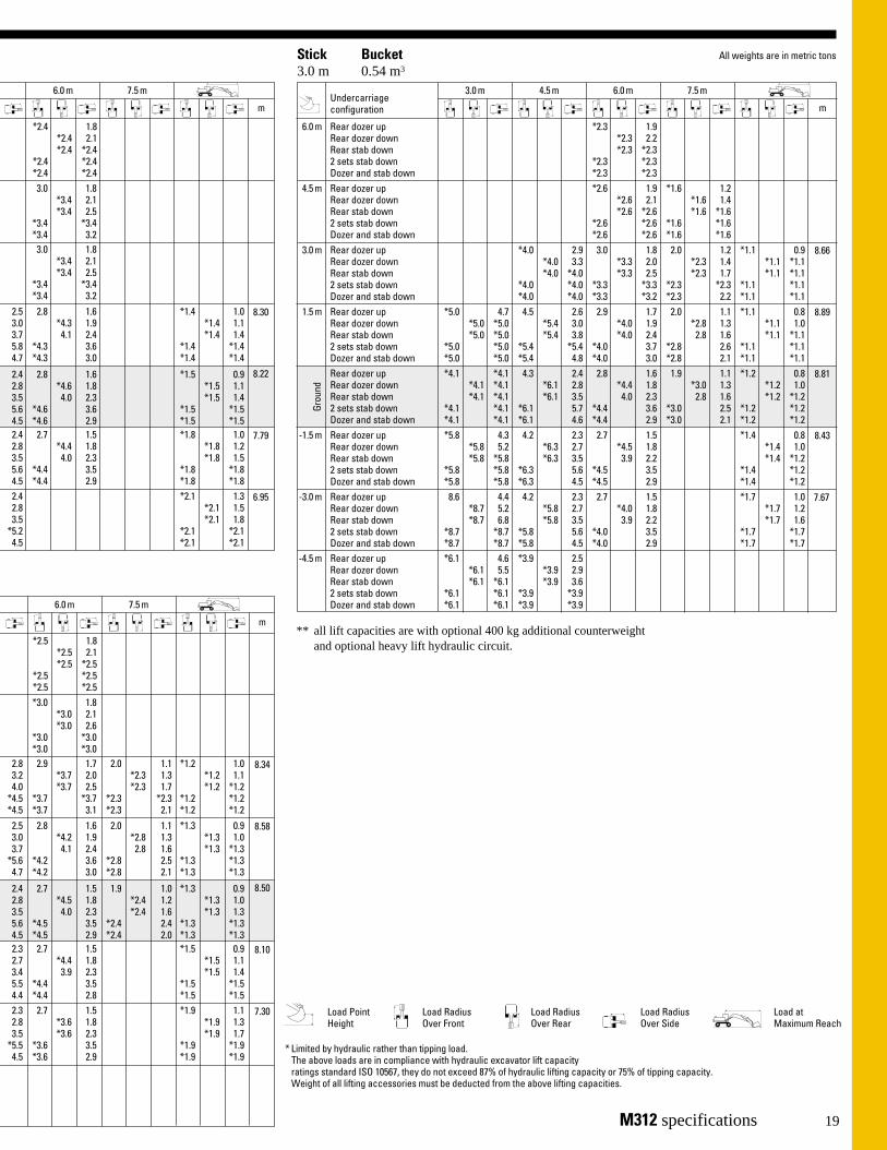
* Limited by hydraulic rather than tipping load.The above loads are in compliance with hydraulic excavator lift capacity ratings standard ISO 10567, they do not exceed 87% of hydraulic lifting capacity or 75% of tipping capacity. Weight of all lifting accessories must be deducted from the above lifting capacities.
Load Point Height
Load Radius Over Front
Load Radius Over Side
Load at Maximum Reach
Load Radius Over Rear
19
All weights are in metric tons
8.30
7.79
*2.4 1.8*2.4 2.1*2.4 *2.4
*2.4 *2.4*2.4 *2.4
6.0 m 7.5 m
m
8.22
3.0 1.8*3.4 2.1*3.4 2.5
*3.4 *3.4*3.4 3.23.0 1.8
*3.4 2.1*3.4 2.5
*3.4 *3.4*3.4 3.2
2.5 2.8 1.6 *1.4 1.03.0 *4.3 1.9 *1.4 1.13.7 4.1 2.4 *1.4 1.45.8 *4.3 3.6 *1.4 *1.44.7 *4.3 3.0 *1.4 *1.4
2.4 2.8 1.6 *1.5 0.92.8 *4.6 1.8 *1.5 1.13.5 4.0 2.3 *1.5 1.45.6 *4.6 3.6 *1.5 *1.54.5 *4.6 2.9 *1.5 *1.52.4 2.7 1.5 *1.8 1.02.8 *4.4 1.8 *1.8 1.23.5 4.0 2.3 *1.8 1.55.6 *4.4 3.5 *1.8 *1.84.5 *4.4 2.9 *1.8 *1.82.4 *2.1 1.32.8 *2.1 1.53.5 *2.1 1.8
*5.2 *2.1 *2.14.5 *2.1 *2.1
6.95
2.3 2.7 1.5 *1.9 1.12.8 *3.6 1.8 *1.9 1.33.5 *3.6 2.3 *1.9 1.7
*5.5 *3.6 3.5 *1.9 *1.94.5 *3.6 2.9 *1.9 *1.9
7.30
8.34
8.58
8.10
*2.5 1.8*2.5 2.1*2.5 *2.5
*2.5 *2.5*2.5 *2.5
6.0 m 7.5 m
m
8.50
*3.0 1.8*3.0 2.1*3.0 2.6
*3.0 *3.0*3.0 *3.0
2.8 2.9 1.7 2.0 1.1 *1.2 1.03.2 *3.7 2.0 *2.3 1.3 *1.2 1.14.0 *3.7 2.5 *2.3 1.7 *1.2 *1.2
*4.5 *3.7 *3.7 *2.3 *2.3 *1.2 *1.2*4.5 *3.7 3.1 *2.3 2.1 *1.2 *1.22.5 2.8 1.6 2.0 1.1 *1.3 0.93.0 *4.2 1.9 *2.8 1.3 *1.3 1.03.7 4.1 2.4 2.8 1.6 *1.3 *1.3
*5.6 *4.2 3.6 *2.8 2.5 *1.3 *1.34.7 *4.2 3.0 *2.8 2.1 *1.3 *1.3
2.4 2.7 1.5 1.9 1.0 *1.3 0.92.8 *4.5 1.8 *2.4 1.2 *1.3 1.03.5 4.0 2.3 *2.4 1.6 *1.3 1.35.6 *4.5 3.5 *2.4 2.4 *1.3 *1.34.5 *4.5 2.9 *2.4 2.0 *1.3 *1.32.3 2.7 1.5 *1.5 0.92.7 *4.4 1.8 *1.5 1.13.4 3.9 2.3 *1.5 1.45.5 *4.4 3.5 *1.5 *1.54.4 *4.4 2.8 *1.5 *1.5
*6.1 4.6 *3.9 2.5*6.1 5.5 *3.9 2.9*6.1 *6.1 *3.9 3.6
*6.1 *6.1 *3.9 *3.9*6.1 *6.1 *3.9 *3.9
8.66
8.89
8.43
Stick3.0 m
Bucket0.54 m3
*2.3 1.9*2.3 2.2*2.3 *2.3
*2.3 *2.3*2.3 *2.3*2.6 1.9 *1.6 1.2
*2.6 2.1 *1.6 1.4*2.6 *2.6 *1.6 *1.6
*2.6 *2.6 *1.6 *1.6*2.6 *2.6 *1.6 *1.6
*4.0 2.9 3.0 1.8 2.0 1.2 *1.1 0.9*4.0 3.3 *3.3 2.0 *2.3 1.4 *1.1 *1.1*4.0 *4.0 *3.3 2.5 *2.3 1.7 *1.1 *1.1
*4.0 *4.0 *3.3 *3.3 *2.3 *2.3 *1.1 *1.1*4.0 *4.0 *3.3 *3.2 *2.3 2.2 *1.1 *1.1
*5.0 4.7 4.5 2.6 2.9 1.7 2.0 1.1 *1.1 0.8*5.0 *5.0 *5.4 3.0 *4.0 1.9 *2.8 1.3 *1.1 1.0*5.0 *5.0 *5.4 3.8 *4.0 2.4 2.8 1.6 *1.1 *1.1
*5.0 *5.0 *5.4 *5.4 *4.0 3.7 *2.8 2.6 *1.1 *1.1*5.0 *5.0 *5.4 4.8 *4.0 3.0 *2.8 2.1 *1.1 *1.1*4.1 *4.1 4.3 2.4 2.8 1.6 1.9 1.1 *1.2 0.8
*4.1 *4.1 *6.1 2.8 *4.4 1.8 *3.0 1.3 *1.2 1.0*4.1 *4.1 *6.1 3.5 4.0 2.3 2.8 1.6 *1.2 *1.2
*4.1 *4.1 *6.1 5.7 *4.4 3.6 *3.0 2.5 *1.2 *1.2*4.1 *4.1 *6.1 4.6 *4.4 2.9 *3.0 2.1 *1.2 *1.2*5.8 4.3 4.2 2.3 2.7 1.5 *1.4 0.8
*5.8 5.2 *6.3 2.7 *4.5 1.8 *1.4 1.0*5.8 *5.8 *6.3 3.5 3.9 2.2 *1.4 *1.2
*5.8 *5.8 *6.3 5.6 *4.5 3.5 *1.4 *1.2*5.8 *5.8 *6.3 4.5 *4.5 2.9 *1.4 *1.28.6 4.4 4.2 2.3 2.7 1.5 *1.7 1.0
*8.7 5.2 *5.8 2.7 *4.0 1.8 *1.7 1.2*8.7 6.8 *5.8 3.5 3.9 2.2 *1.7 1.6
*8.7 *8.7 *5.8 5.6 *4.0 3.5 *1.7 *1.7*8.7 *8.7 *5.8 4.5 *4.0 2.9 *1.7 *1.7
6.0 m
Grou
nd
3.0 m 4.5 m 6.0 m 7.5 m
m
4.5 m
3.0 m
1.5 m
-1.5 m
-3.0 m
Rear dozer upRear dozer downRear stab down2 sets stab downDozer and stab downRear dozer upRear dozer downRear stab down2 sets stab downDozer and stab downRear dozer upRear dozer downRear stab down2 sets stab downDozer and stab downRear dozer upRear dozer downRear stab down2 sets stab downDozer and stab downRear dozer upRear dozer downRear stab down2 sets stab downDozer and stab down
8.81
Rear dozer upRear dozer downRear stab down2 sets stab downDozer and stab down
Rear dozer upRear dozer downRear stab down2 sets stab downDozer and stab down
Undercarriage configuration
-4.5 m Rear dozer upRear dozer downRear stab down2 sets stab downDozer and stab down
7.67
** all lift capacities are with optional 400 kg additional counterweightand optional heavy lift hydraulic circuit.

Lift capacities**with hydraulically adjustable boom – 5.05 m
7.65
7.91
7.38
Stick1.6 m
Bucket0.68 m3
*3.8 3.0*3.8 3.4*3.8 *3.8
*3.8 *3.8*3.8 *3.8*4.3 3.0 3.0 1.7
*4.3 3.4 *3.7 2.0*4.3 *4.1 *3.7 2.5
*4.3 *4.3 *3.7 *3.7*4.3 *4.3 *3.7 3.14.6 2.9 3.0 1.7 2.0 1.1
*5.3 3.3 *4.0 2.0 *2.4 1.3*5.3 4.0 *4.0 2.5 *2.4 1.6
*5.3 *5.7 *4.0 *3.7 *2.4 *2.4*5.3 4.8 *4.0 *3.1 *2.4 2.1
*6.5 5.3 4.6 *2.9 2.9 1.7 1.8 1.0*6.5 6.0 *5.9 *3.3 *4.3 1.9 *2.5 1.2*6.5 *6.5 *5.9 4.0 *4.1 2.4 *2.5 1.5
*6.5 *6.5 *5.9 *5.7 *4.3 3.7 *2.5 *2.3*6.5 *6.5 *5.9 4.8 *4.3 3.1 *2.5 1.9*9.1 5.1 4.8 2.8 2.8 1.6 1.8 1.0
*9.1 6.0 *6.2 3.2 *4.5 1.9 *2.6 1.1*9.1 7.6 *6.2 4.0 *4.5 2.3 *2.6 1.5
*9.1 *9.1 *6.2 5.8 *4.5 3.6 *2.6 2.3*9.1 *9.1 *6.2 4.9 *4.1 3.0 *2.6 1.99.5 5.0 4.5 2.6 2.7 1.5 2.0 1.1
*10.3 5.9 *6.4 3.0 *4.2 1.8 *2.9 1.3*10.3 7.6 *6.4 3.8 *4.2 2.2 *2.9 1.6
*10.3 *10.3 *6.4 *5.9 *4.2 3.5 *2.9 2.6*10.3 9.9 *6.4 4.8 *4.0 2.9 *2.9 2.1*9.3 4.8 4.4 2.4
*9.8 5.7 *5.1 2.9*9.8 7.4 *5.1 3.6
*9.8 *9.8 *5.1 *5.1*9.8 *9.8 *5.1 4.6
6.0 m
Grou
nd
3.0 m 4.5 m 6.0 m 7.5 m
m
4.5 m
3.0 m
1.5 m
-1.5 m
-3.0 m
Rear dozer upRear dozer downRear stab down2 sets stab downDozer and stab downRear dozer upRear dozer downRear stab down2 sets stab downDozer and stab downRear dozer upRear dozer downRear stab down2 sets stab downDozer and stab downRear dozer upRear dozer downRear stab down2 sets stab downDozer and stab downRear dozer upRear dozer downRear stab down2 sets stab downDozer and stab down
7.83
Rear dozer upRear dozer downRear stab down2 sets stab downDozer and stab down
Rear dozer upRear dozer downRear stab down2 sets stab downDozer and stabdown
Undercarriage configuration
8.05
8.30
7.79
Stick2.0 m
Bucket0.61 m3
*3.5 3.1 *2.9 1.8*3.5 *3.5 *2.9 2.1*3.5 *3.5 *2.9 2.5
*3.5 *3.5 *2.9 *2.9*3.5 *3.5 *2.9 *2.9
*4.3 *4.3 *4.1 *3.0 3.1 1.8*4.3 *4.3 *4.1 *3.4 *3.5 2.1*4.3 *4.3 *4.1 *4.1 *3.5 2.6
*4.3 *4.3 *4.1 *4.1 *3.5 *3.5*4.3 *4.3 *4.1 *4.1 *3.5 3.2*5.9 5.4 4.7 3.0 3.1 1.8 *1.6 1.0
*5.9 *5.9 *5.1 3.4 *3.9 2.1 *1.6 1.2*5.9 *5.9 *5.1 *4.0 *3.9 2.6 *1.6 *1.5
*5.9 *5.9 *5.1 *5.1 *3.9 *3.8 *1.6 *1.6*5.9 *5.9 *5.1 *4.9 *3.9 3.2 *1.6 *1.6*6.6 *5.3 4.7 3.0 3.0 1.8 *1.6 0.9
*6.6 6.0 *5.9 *3.3 *4.3 2.1 *1.6 1.1*6.6 *6.6 *5.9 4.0 *4.3 2.6 *1.6 1.4
*6.6 *6.6 *5.9 *5.8 *4.3 *3.8 *1.6 *1.6*6.6 *6.6 *5.9 4.8 *4.1 3.2 *1.6 *1.6*9.1 5.2 4.8 2.8 2.9 1.7 *1.7 0.9
*9.1 6.1 *6.3 3.3 *4.5 2.0 *1.7 1.1*9.1 7.6 *6.3 4.0 4.5 2.4 *1.7 1.4
*9.1 *9.1 *6.3 *5.8 *4.5 3.2 *1.7 *1.7*9.1 *9.1 *6.3 4.9 *4.2 3.1 *1.7 *1.79.5 5.0 4.6 2.7 2.8 1.6 *1.8 1.0
*10.3 5.9 *6.4 3.3 *4.5 1.8 *1.9 1.2*10.3 7.6 *6.4 3.8 4.1 2.3 *1.9 1.5
*10.3 *10.3 *6.4 6.0 *4.5 3.6 *1.9 *1.9*10.3 *9.8 *6.4 4.9 *4.5 3.0 *1.9 *1.9
9.5 5.0 4.5 2.5 *2.2 1.2*10.6 5.9 *6.0 2.9 *2.2 1.5*10.6 7.6 *6.0 3.7 *2.2 1.8
*10.6 *10.6 *6.0 *5.9 *2.2 *2.2*10.6 *10.6 *6.0 4.7 *2.2 *2.2
6.0 m
Grou
nd
3.0 m 4.5 m 6.0 m 7.5 m
m
4.5 m
3.0 m
1.5 m
-1.5 m
-3.0 m
Rear dozer upRear dozer downRear stab down2 sets stab downDozer and stab downRear dozer upRear dozer downRear stab down2 sets stab downDozer and stab downRear dozer upRear dozer downRear stab down2 sets stab downDozer and stab downRear dozer upRear dozer downRear stab down2 sets stab downDozer and stab downRear dozer upRear dozer downRear stab down2 sets stab downDozer and stab down
8.22
Rear dozer upRear dozer downRear stab down2 sets stab downDozer and stab down
Rear dozer upRear dozer downRear stab down2 sets stab downDozer and stab down
Undercarriage configuration
6.95
Stick2.3 m
Bucket0.54 m3
*3.1*3.1*3.1
*3.1*3.1
6.0 m
Grou
nd
3.0 m 4.5 m
4.5 m
3.0 m
1.5 m
-1.5 m
-3.0 m
Rear dozer upRear dozer downRear stab down2 sets stab downDozer and stab downRear dozer upRear dozer downRear stab down2 sets stab downDozer and stab downRear dozer upRear dozer downRear stab down2 sets stab downDozer and stab downRear dozer upRear dozer downRear stab down2 sets stab downDozer and stab downRear dozer upRear dozer downRear stab down2 sets stab downDozer and stab down
Rear dozer upRear dozer downRear stab down2 sets stab downDozer and stab down
Rear dozer upRear dozer downRear stab down2 sets stab downDozer and stab down
Undercarriage configuration
*3.0 *3.0 *3.5*3.0 *3.0 *3.5*3.0 *3.0 *3.5
*3.0 *3.0 *3.5*3.0 *3.0 *3.5*5.1 *5.1 *4.7
*5.1 *5.1 *4.8*5.1 *5.1 *4.8
*5.1 *5.1 *4.8*5.1 *5.1 *4.8*6.9 5.3 4.6
*6.9 6.0 *5.8*6.9 *6.9 *5.8
*6.9 *6.9 *5.8*6.9 *6.9 *5.8
*8.7 5.3 4.7*8.7 6.2 *6.2*8.7 *7.6 *6.2
*8.7 *8.7 *6.2*8.7 *8.7 *6.2*9.4 5.0 4.7
*10.2 6.0 *6.3*10.2 7.6 *6.3
*10.2 *10.2 *6.3*10.2 *9.7 *6.3
9.5 5.0 4.5*10.7 6.0 *6.3*10.7 7.6 *6.3
*10.7 *10.7 *6.3*10.7 *10.1 *6.3
-3.0 m Rear dozer upRear dozer downRear stab down2 sets stab downDozer and stab down
9.5 5.0 4.5*10.4 5.9 *6.5*10.4 7.6 *6.5
*10.4 *10.4 *6.5*10.4 *10.0*6.5
Stick2.6 m
Bucket0.54 m3
*2.7*2.7*2.7
*2.7*2.7
6.0 mGr
ound
3.0 m 4.5 m
4.5 m
3.0 m
1.5 m
-1.5 m
Rear dozer upRear dozer downRear stab down2 sets stab downDozer and stab downRear dozer upRear dozer downRear stab down2 sets stab downDozer and stab downRear dozer upRear dozer downRear stab down2 sets stab downDozer and stab downRear dozer upRear dozer downRear stab down2 sets stab downDozer and stab down
Rear dozer upRear dozer downRear stab down2 sets stab downDozer and stab down
Rear dozer upRear dozer downRear stab down2 sets stab downDozer and stab down
Undercarriage configuration
*3.0*3.0*3.0
*3.0*3.0
*5.3 *5.3 *4.6*5.3 *5.3 *4.6*5.3 *5.3 *4.6
*5.3 *5.3 *4.6*5.3 *5.3 *4.6*7.0 5.2 4.6
*7.0 6.1 *5.6*7.0 *7.0 *5.6
*7.0 *7.0 *5.6*7.0 *7.0 *5.6
*8.1 5.3 4.6*8.1 6.1 *6.1*8.1 7.4 *6.1
*8.1 *8.1 *6.1*8.1 *8.1 *6.19.2 5.0 4.7
*10.0 5.9 *6.3*10.0 7.6 *6.3
*10.0 *10.0 *6.3*10.0 *9.6 *6.3
-4.5 m Rear dozer upRear dozer downRear stab down2 sets stab downDozer and stab down
*8.0 4.8*8.0 5.7*8.0 7.3
*8.0 *8.0*8.0 *8.0

M312 specifications 21
* Limited by hydraulic rather than tipping load.The above loads are in compliance with hydraulic excavator lift capacity ratings standard ISO 10567, they do not exceed 87% of hydraulic lifting capacity or 75% of tipping capacity. Weight of all lifting accessories must be deducted from the above lifting capacities.
All weights are in metric tons
Load Point Height
Load Radius Over Front
Load Radius Over Side
Load at Maximum Reach
Load Radius Over Rear
8.35
8.59
8.11
*3.1 *3.0 1.8*3.1 *3.0 2.1*3.1 *3.0 2.6*3.1 *3.0 *3.0*3.1 *3.0 *3.0
6.0 m 7.5 m
m
8.51
3.1 3.1 1.9*3.5 *3.4 *2.2*3.5 *3.4 2.7*3.5 *3.4 *3.4*3.5 *3.4 *3.23.0 3.1 1.9 2.0 1.1 *1.4 1.0
*3.4 *3.8 *2.2 *2.7 1.3 *1.4 1.14.0 *3.8 2.6 *2.7 1.7 *1.4 *1.4
*4.8 *3.8 *3.8 *2.7 *2.6 *1.4 *1.4*4.8 *3.8 3.2 *2.7 2.1 *1.4 *1.42.9 3.1 1.9 2.0 1.1 *1.4 0.93.3 *4.2 2.1 *3.2 1.3 *1.4 1.04.0 *4.1 2.6 2.8 1.6 *1.4 *1.3
*5.8 *4.2 3.7 *3.3 2.6 *1.4 *1.44.9 *4.2 3.2 *3.3 2.1 *1.4 *1.4
2.9 3.0 1.7 1.9 1.1 *1.5 0.93.3 *4.5 2.0 *2.8 1.3 *1.5 1.04.0 4.2 2.5 *2.8 1.6 *1.5 1.35.8 *4.5 3.8 *2.8 2.5 *1.5 *1.54.9 *4.5 3.1 *2.8 2.1 *1.5 *1.52.7 2.8 1.6 *1.7 0.93.2 *4.5 1.9 *1.7 1.13.9 4.1 2.3 *1.7 1.46.0 *4.5 3.7 *1.7 *1.75.0 *4.5 3.0 *1.7 *1.72.5 2.8 1.5 *2.0 1.13.0 *3.4 1.8 *2.0 1.33.7 *3.4 2.3 *2.0 1.7
*5.9 *3.4 *3.4 *2.0 *2.04.7 *3.4 2.9 *2.0 *2.0
7.31
2.5 2.7 1.5 *1.7 1.02.9 *3.9 1.8 *1.7 1.23.7 *3.9 2.3 *1.7 1.55.9 *3.9 3.6 *1.7 *1.74.7 *3.9 2.9 *1.7 *1.7
7.66
8.65
8.88
8.42
*2.7 *2.8 1.9*2.7 *2.8 2.2*2.7 *2.8 *2.6*2.7 *2.8 *2.8*2.7 *2.8 *2.8
6.0 m 7.5 m
m
8.80
*3.0 *3.1 1.9 *1.9 1.1*3.0 *3.1 2.2 *1.9 1.3*3.0 *3.1 2.7 *1.9 1.7*3.0 *3.1 *3.1 *1.9 *1.9*3.0 *3.1 *3.1 *1.9 *1.93.0 3.0 1.9 2.0 1.1 *1.2 0.93.3 *3.6 2.2 *2.9 1.3 *1.2 1.14.0 *3.6 2.6 *2.9 1.7 *1.2 *1.2
*4.6 *3.6 *3.6 *2.9 2.6 *1.2 *1.2*4.6 *3.6 3.2 *2.9 2.1 *1.2 *1.22.9 3.0 1.9 2.0 1.1 *1.2 0.83.3 *4.1 2.1 *3.2 1.3 *1.2 1.0
*3.9 *4.1 2.6 2.3 1.7 *1.2 *1.2*5.6 *4.1 3.7 *3.2 2.6 *1.2 *1.24.8 *4.1 3.1 *3.2 2.1 *1.2 *1.2
2.9 3.0 1.8 1.9 1.0 *1.3 0.8*3.3 *4.4 2.0 *3.2 1.2 *1.3 1.04.0 4.1 2.5 2.8 1.6 *1.3 1.35.7 *4.4 3.8 *3.4 2.5 *1.3 *1.5
*4.8 *4.4 3.1 3.4 2.1 *1.3 *1.52.7 2.8 1.6 *1.5 0.83.2 *4.5 1.9 *1.5 1.03.9 4.1 2.3 *1.5 1.3
*5.9 *4.5 3.7 *1.5 *1.55.0 *4.5 3.0 *1.5 *1.5
*9.2 4.8 4.4 2.5*9.3 5.7 *4.9 2.9*9.3 7.3 *4.9 3.6
*9.3 *9.3 *4.9 *4.9*9.3 *9.3 *4.9 *4.9
8.98
9.20
8.76
Stick3.0 m
Bucket0.40 m3
*2.4 2.0*2.4 2.4*2.4 *2.4
*2.4 *2.4*2.4 *2.4
*2.5 *2.5 *2.7 2.0 *2.1 1.2*2.5 *2.5 *2.7 2.2 *2.1 1.4*2.5 *2.5 *2.7 *2.7 *2.1 1.8
*2.5 *2.5 *2.7 *2.7 *2.1 *2.1*2.5 *2.5 *2.7 *2.7 *2.1 *2.1
*5.4 *5.4 *4.3 3.0 3.1 1.9 *2.1 1.2 *1.1 0.9*5.4 *5.4 *4.3 3.4 *3.4 2.2 *2.7 1.4 *1.1 *1.0*5.4 *5.4 *4.3 *4.1 *3.4 2.7 *2.7 *1.8 *1.1 *1.1
*5.4 *5.4 *4.3 *4.3 *3.4 *3.4 *2.7 *2.7 *1.1 *1.1*5.4 *5.4 *4.3 *4.3 *3.4 *3.2 *2.7 2.2 *1.1 *1.1*7.0 5.2 4.6 2.9 3.0 1.9 2.1 1.2 *1.1 0.8
*7.0 6.1 *5.4 3.3 *4.0 2.2 *3.3 1.4 *1.1 0.9*7.0 *7.0 *5.4 *4.0 *4.0 2.6 2.9 1.7 *1.1 *1.1
*7.0 *7.0 *5.4 *5.4 *4.0 *3.8 *3.3 2.6 *1.1 *1.1*7.0 *7.0 *5.4 4.9 *4.0 3.2 *3.3 *2.2 *1.1 *1.1*8.2 *5.3 4.6 3.1 3.1 1.9 2.0 1.1 *1.2 0.8
*8.2 6.0 *6.1 *3.9 *4.4 *2.1 *3.2 1.3 *1.2 0.9*8.2 7.4 *6.1 4.0 *4.1 2.6 2.8 1.7 *1.2 *1.2
*8.2 *8.2 *6.1 *5.7 *4.4 *3.7 *3.4 *2.6 *1.2 *1.2*8.2 *8.2 *6.1 *4.8 *4.4 3.2 *3.4 2.1 *1.2 *1.29.1 5.1 4.8 2.8 2.9 1.7 1.9 1.0 *1.3 0.8
*9.7 6.0 *6.2 3.2 *4.5 2.0 *2.9 1.2 *1.3 1.0*9.7 7.7 *6.2 4.0 4.1 2.5 *2.8 1.6 *1.3 *1.3
*9.7 *9.7 *6.2 *5.8 *4.5 3.7 *2.9 2.5 *1.3 *1.3*9.7 *9.5 *6.2 4.9 *4.5 3.1 *2.9 2.0 *1.3 *1.39.5 5.0 4.5 2.6 2.8 1.6 *1.6 0.9
*10.3 5.9 *6.4 3.0 *4.3 1.8 *1.6 1.1*10.3 7.5 *6.4 3.8 *4.0 2.3 *1.6 1.4
*10.3 *10.3 *6.4 5.9 *4.3 3.6 *1.6 *1.6*10.3 *10.0 *6.4 4.8 *4.3 2.9 *1.6 *1.6
6.0 m
Grou
nd
3.0 m 4.5 m 6.0 m 7.5 m
m
4.5 m
3.0 m
1.5 m
-1.5 m
-3.0 m
Rear dozer upRear dozer downRear stab down2 sets stab downDozer and stab downRear dozer upRear dozer downRear stab down2 sets stab downDozer and stab downRear dozer upRear dozer downRear stab down2 sets stab downDozer and stab downRear dozer upRear dozer downRear stab down2 sets stab downDozer and stab downRear dozer upRear dozer downRear stab down2 sets stab downDozer and stab down
9.13
Rear dozer upRear dozer downRear stab down2 sets stab downDozer and stab down
Rear dozer upRear dozer downRear stab down2 sets stab downDozer and stab down
Undercarriage configuration
-4.5 m Rear dozer upRear dozer downRear stab down2 sets stab downDozer and stab down
8.04
** all lift capacities are with optional additional counterweight and optional heavy lift hydraulic circuit.

Standard equipmentThe M312 is a worldwide model from Caterpillar. To provide you with the optimum configuration for your jobs, standard andoptional equipment may vary. Please ask your Cat dealer for the latest equipment list for your country.
Optional equipment
Additional counterweight, 400 kgAir conditionerAir hornAir suspension seatAlarm, back-upAnti-drift valve
For VA boom cylinderFor stick cylinderFor bucket cylinder
Auxiliary hydraulic circuits (AHC):Medium pressure circuit for booms
and sticksHigh pressure circuit for booms
and sticksHammer circuit for booms and sticks
Biodegradable hydraulic oilBooms
One piece boomHydraulically adjustable (VA)Offset VA boom
BucketsBucket linkage
With diverter valveWithout diverter valve
Cab, deluxe (openable side window)Cab riser, 1.2 m, fixed
Check valvesBoom cylindersStick cylinderVA cylinder
Clamshell restraintDozer blade, front or rear mountedGuards
Cab roof (FOPS)Front windowVandalism protection
Headrest for driver’s seatHeavy lift arrangementLights
Warning, stick mountedWorking for all boomsWorking, front, cab mounted (2x)Working, rear, cab mounted (1x)
Outriggers, pin-on, individuallycontrolled
1 set, front or rear mounted2 sets, front and rear mounted
Overload warning deviceRain protective shade for front
windscreenRadio Mounting Kit with loudspeakers
and antenna (does not include radio)Radio (includes Radio Mounting Kit)
Refuelling pump, electricRotating beaconSpacer rings, rubber, for use between
dual tiresSticks
1600 mm2000 mm2300 mm2600 mm3000 mm2800 mm material handling
Sound suppression screenSun blinds
For polycarbonate skylightFor rear windscreenFor right side windscreen
Supplemental steeringTilting device (for ditch cleaning
buckets only)TiresTip groupsTool box, left and/or right
undercarriage-mountedTravel speed lockTwo-piece drive-shaftWiper and washer for lower front
windscreen
Adjustable pilot operated joystick typelever controls
Alternator, 55-amp.Automatic engine speed control (AEC)Batteries, 2 CaterpillarCab with:
Ash tray and lighterBottle holderCoat hookCooler box behind operators seatFloor matGlass, tempered and tinted,
EC approved, pressurized and sound suppressed
Heater and defrosterHydraulic lock, left side console
activatedInterior lightingLiterature compartment
Roading lights including headlights,taillights and turning lights
Suspension seat with: adjustablearmrests, lumbar support andretractable seat belt
Warning hornCat 3054 TA diesel engine, emission
controlled, 85 kW at 2000 rpm24 Volt electric starting2300 m altitude capacity
Downshift inhibitorDual tires 10.00-20Electronic Power Control Unit with
backup systemFully hydraulic braking systemFull hydraulic steering with emergency
steering capabilityHydraulic maximum speed limiterHydrostatic drive 2 speed,
4 wheel drive with on-the-go shifting
Lockable oscillating front axlePower mode selector, economy and
standardOne-piece drive-shaftOpenable two piece front windshield
and openable skylightParking brakePrepared for optional pin-on dozer
blade and/or outriggers for frontand/or rear installation
Positive filtered ventilation, 3 speedRearview mirror, left and rightSteering column, tiltableSwing brake, automaticVariable displacement, load sensing
hydraulic systemWide steps on both sidesWiper and washer
Machines bearing the EC mark, comply with EU Machinery Directive 89/392/EEC pertaining to essential health and safety requirements.

23
Cat ‘5-Star Customer Service’Purchase a Cat M312. You know it’s ‘equipped’ with something unique and dependable – Cat ‘5-Star Customer Service’ as delivered by your Cat dealer.
Cat ‘5-Star Customer Service’ meanspeace of mind from the minute youcontact your Cat dealer. By building apartnership with your Cat dealer, youcan focus on your business instead ofyour equipment. Cat ‘5-Star CustomerService’ brings together all theproducts, services and people fromCaterpillar and the Cat dealer networkand puts them firmly behind you. Count on them to help you maintainyour competitive edge.
Cat ‘5-Star Customer Service’ includesEquipment Management Services tohelp you make a better businessdecision. We’ll assist you in selectingthe right Cat equipment to suit yourneed, to optimize productivity. And we’ll help you make smarterdecisions, assist you with machineselection, purchasing or renting options,financing, and projected owning andoperating costs.
Maintenance Services that enable youto maximize machine availability andperformance. Every Cat dealer has awide choice of maintenance productsand services to make sure your equip-ment achieves maximum performancefor the lowest possible cost.
Predictive Services to anticipateproblems. By anticipating potentialproblems and preventing unscheduledrepairs, Cat Predictive Services makesure that your equipment is always upand ready to run – because maximizinguptime means maximum earningcapacity.
“Cat 5-Star Customer Service is ourcommitment to provide you with the best equipment and services for the most cost effective solutions in your business.”Caterpillar and Cat dealers
Reconditioning Services for a widerchoice of repair alternatives.Caterpillar factory-reconditioned partsand components get your equipmentback on the job in the minimum of time and with lower repair costs,contributing to reduced operating costsand a more efficient operation.
Off-the shelf availability of genuine Cat parts. Genuine parts, together with highly experienced, Cat-trainedspecialists make sure every repair isright first time and your machine isback earning its keep in the shortestpossible time.

M312 Wheel Excavator
www.CAT.com
© 2000 CaterpillarHEHH2052-1 (04/2000) hr
Featured photos of machines may not always include standard equipment. See your Caterpillar Dealer for available options.
Materials and specifications are subject to change without notice.
®