Embed Size (px)
Citation preview
Wheel Balancer Manual
----A
Warning
This manual is a necessary part of the product. Please read carefully.
Keep the manual for later use when maintaining the machine.
This machine can only be used for the designated purposes. Never use it for any other purpose.
The manufacturer is not responsible for the damage incurred by improper use or use other than the
intended purpose.
Precaution
The equipment can only be operated by qualified personnel with special training. Modification to any
components or parts, or use the machine for other purpose without either obtaining the agreement from the producer,
or observing the requirement of the instructions may lead to direct or indirect damage to the equipment.
★ The equipment should be installed on the stable ground, not wooden pallet, otherwise not accurate.
Keep the back panel 0.6M away from the wall for good ventilation. Enough room should be left on both
sides for convenient operation.
Do not put the equipment a place with high temperature or moisture, or near the heating system, water tap,
air-humidifier or chimney.
Avoid lots of dust, ammonia, alcohol, thinner or spraying binder.
People who are no operating the machines should be kept away when it is used.
Use appropriate equipment and tools, protective and safety equipment, including eyeglasses, earplugs and
working boots.
Pay special attention to the marks on the machine.
Do not touch or approach the moving parts by hand during operating.
Do not remove the safety device or keep it from working properly.
0
Contents
1. General-----------------------------------------------------------------------------------------------------------------1
2. Machine assembly----------------------------------------------------------------------------------------------------1
3. Controls and components--------------------------------------------------------------------------------------------3
4. Indication and use of wheel balancer------------------------------------------------------------------------------5
5. Self-calibration --------------------------------------------------------------------------------------------------11
6. Errors------------------------------------------------------------------------------------------------------------------14
7. Self- diagnoses-------------------------------------------------------------------------------------------------------15
8. Setting machine------------------------------------------------------------------------------------------------------15
9. OPT function --------------------------------------------------------------------------------------------------------16
10. Spare parts list and Exploded drawings ------------------------------------------------------------------------17
1
1. General
1.1. Technical data:
Max wheel weight:65kg
Power:0.2kw;0.37kw
Power supply: 220v;230v;240v;110v;50hz;60hz
Balancing accuracy: 1g
5 balancing modes: DYN, ALU1, ALU2,ALUS, ST
Balancing speed:200r/min
Cycle time:8s
Rim diameter:10〃~24〃(256mm~610mm)
Sound pressure level during work cycle:<70db
1.2. Features:
Distance and diameter value input automatically
Statistic and dynamic balancing, ALU-programs for alloy rims or special shaped
Self diagnoses, easy to find the problem
Apply to steel and aluminum alloy rim
1.3. Working environment:
Temperature:5~50℃
Height:≤4000m
2.Machine assembly
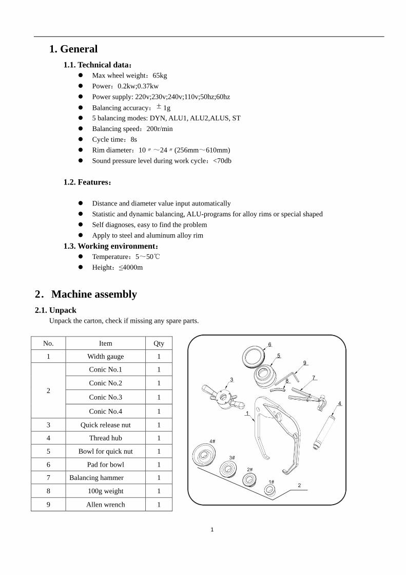
2.1. Unpack
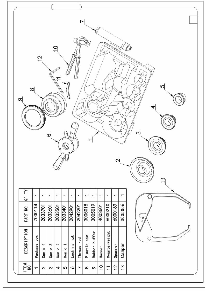
Unpack the carton, check if missing any spare parts.
No. Item Qty
1 Width gauge 1
2
Conic No.1 1
Conic No.2 1
Conic No.3 1
Conic No.4 1
3 Quick release nut 1
4 Thread hub 1
5 Bowl for quick nut 1
6 Pad for bowl 1
7 Balancing hammer 1
8 100g weight 1
9 Allen wrench 1
2
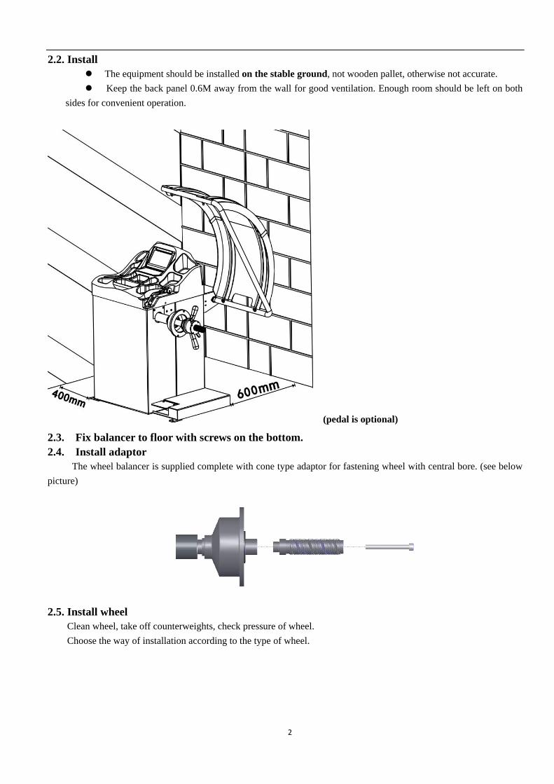
2.2. Install
The equipment should be installed on the stable ground, not wooden pallet, otherwise not accurate.
Keep the back panel 0.6M away from the wall for good ventilation. Enough room should be left on both
sides for convenient operation.
(pedal is optional)
2.3. Fix balancer to floor with screws on the bottom.
2.4. Install adaptor
The wheel balancer is supplied complete with cone type adaptor for fastening wheel with central bore. (see below
picture)
2.5. Install wheel
Clean wheel, take off counterweights, check pressure of wheel.
Choose the way of installation according to the type of wheel.
3
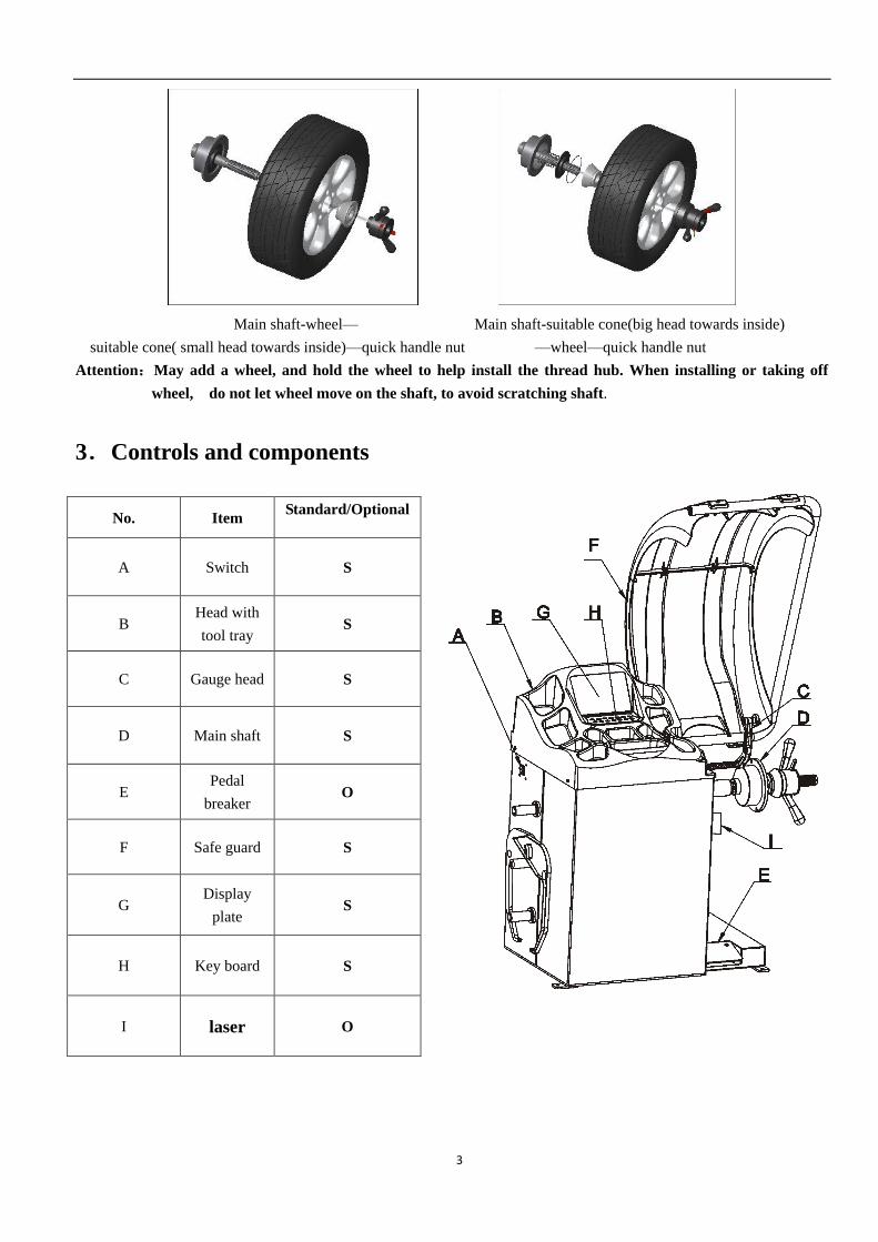
Main shaft-wheel— Main shaft-suitable cone(big head towards inside)
suitable cone( small head towards inside)—quick handle nut —wheel—quick handle nut
Attention:May add a wheel, and hold the wheel to help install the thread hub. When installing or taking off
wheel, do not let wheel move on the shaft, to avoid scratching shaft.
3.Controls and components
No. Item Standard/Optional
A Switch S
B Head with
tool tray S
C Gauge head S
D Main shaft S
E Pedal
breaker O
F Safe guard S
G Display
plate S
H Key board S
I laser O
4
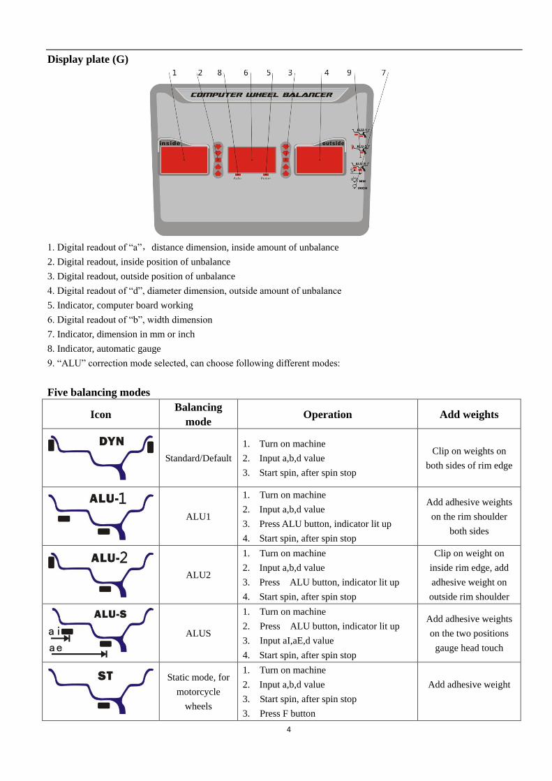
Display plate (G)
1. Digital readout of “a”,distance dimension, inside amount of unbalance
2. Digital readout, inside position of unbalance
3. Digital readout, outside position of unbalance
4. Digital readout of “d”, diameter dimension, outside amount of unbalance
5. Indicator, computer board working
6. Digital readout of “b”, width dimension
7. Indicator, dimension in mm or inch
8. Indicator, automatic gauge
9. “ALU” correction mode selected, can choose following different modes:
Five balancing modes
Icon Balancing
mode Operation Add weights
Standard/Default
1. Turn on machine
2. Input a,b,d value
3. Start spin, after spin stop
Clip on weights on
both sides of rim edge
ALU1
1. Turn on machine
2. Input a,b,d value
3. Press ALU button, indicator lit up
4. Start spin, after spin stop
Add adhesive weights
on the rim shoulder
both sides
ALU2
1. Turn on machine
2. Input a,b,d value
3. Press ALU button, indicator lit up
4. Start spin, after spin stop
Clip on weight on
inside rim edge, add
adhesive weight on
outside rim shoulder
ALUS
1. Turn on machine
2. Press ALU button, indicator lit up
3. Input aI,aE,d value
4. Start spin, after spin stop
Add adhesive weights
on the two positions
gauge head touch
Static mode, for
motorcycle
wheels
1. Turn on machine
2. Input a,b,d value
3. Start spin, after spin stop
3. Press F button
Add adhesive weight
5
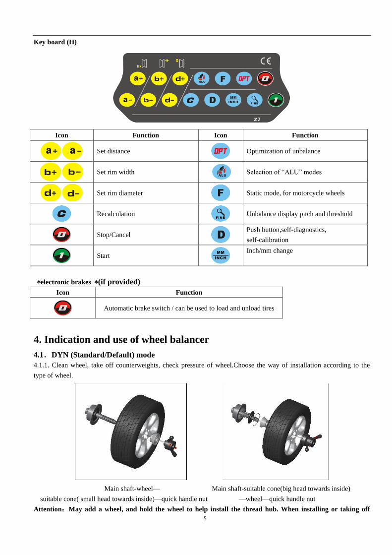
Key board (H)
Icon Function Icon Function
Set distance
Optimization of unbalance
Set rim width
Selection of “ALU” modes
Set rim diameter
Static mode, for motorcycle wheels
Recalculation
Unbalance display pitch and threshold
Stop/Cancel
Push button,self-diagnostics,
self-calibration
Start
Inch/mm change
*electronic brakes *(if provided)
Icon Function
Automatic brake switch / can be used to load and unload tires
4. Indication and use of wheel balancer
4.1.DYN (Standard/Default) mode
4.1.1. Clean wheel, take off counterweights, check pressure of wheel.Choose the way of installation according to the
type of wheel.
Main shaft-wheel— Main shaft-suitable cone(big head towards inside)
suitable cone( small head towards inside)—quick handle nut —wheel—quick handle nut
Attention:May add a wheel, and hold the wheel to help install the thread hub. When installing or taking off
6
wheel, do not let wheel move on the shaft, to avoid scratching shaft.
4.1.2. Turn on machine
4.1.3. Input a b d value
Turn on machine, choose right way to install wheel according to the type of wheel. Set “a” “b” “d”
values:
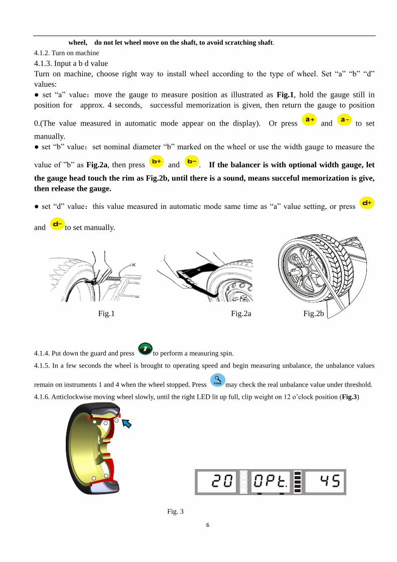
● set “a” value:move the gauge to measure position as illustrated as Fig.1, hold the gauge still in
position for approx. 4 seconds, successful memorization is given, then return the gauge to position
0.(The value measured in automatic mode appear on the display). Or press and to set
manually.
● set “b” value:set nominal diameter “b” marked on the wheel or use the width gauge to measure the
value of ”b” as Fig.2a, then press and . If the balancer is with optional width gauge, let
the gauge head touch the rim as Fig.2b, until there is a sound, means succeful memorization is give,
then release the gauge.
● set “d” value:this value measured in automatic mode same time as “a” value setting, or press
and to set manually.
Fig.1 Fig.2a Fig.2b
4.1.4. Put down the guard and press to perform a measuring spin.
4.1.5. In a few seconds the wheel is brought to operating speed and begin measuring unbalance, the unbalance values
remain on instruments 1 and 4 when the wheel stopped. Press may check the real unbalance value under threshold.
4.1.6. Anticlockwise moving wheel slowly, until the right LED lit up full, clip weight on 12 o’clock position (Fig.3)
Fig. 3
7
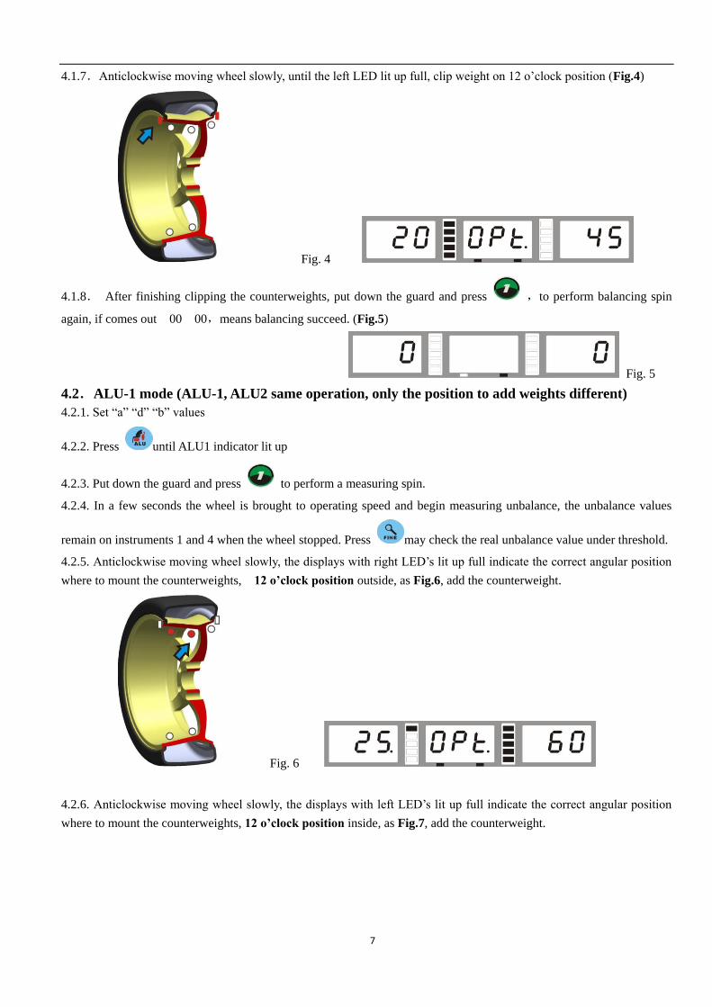
4.1.7.Anticlockwise moving wheel slowly, until the left LED lit up full, clip weight on 12 o’clock position (Fig.4)
Fig. 4
4.1.8. After finishing clipping the counterweights, put down the guard and press ,to perform balancing spin
again, if comes out 00 00,means balancing succeed. (Fig.5)
Fig. 5
4.2.ALU-1 mode (ALU-1, ALU2 same operation, only the position to add weights different)
4.2.1. Set “a” “d” “b” values
4.2.2. Press until ALU1 indicator lit up
4.2.3. Put down the guard and press to perform a measuring spin.
4.2.4. In a few seconds the wheel is brought to operating speed and begin measuring unbalance, the unbalance values
remain on instruments 1 and 4 when the wheel stopped. Press may check the real unbalance value under threshold.
4.2.5. Anticlockwise moving wheel slowly, the displays with right LED’s lit up full indicate the correct angular position
where to mount the counterweights, 12 o’clock position outside, as Fig.6, add the counterweight.
Fig. 6
4.2.6. Anticlockwise moving wheel slowly, the displays with left LED’s lit up full indicate the correct angular position
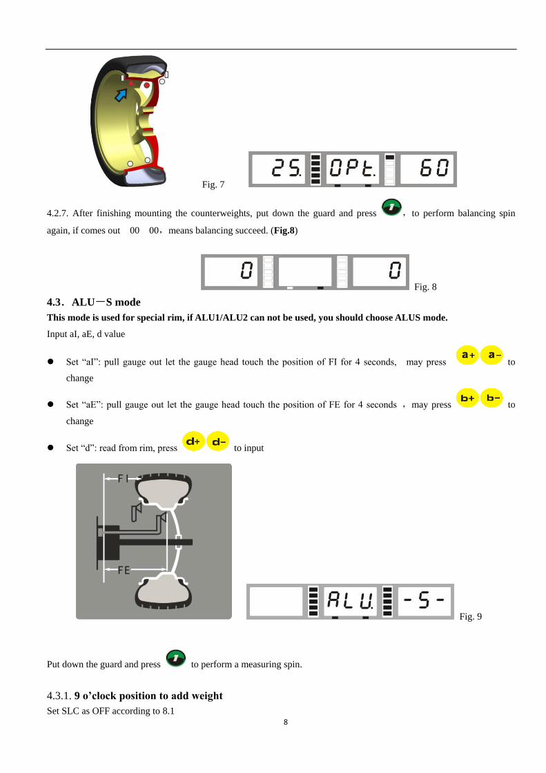
where to mount the counterweights, 12 o’clock position inside, as Fig.7, add the counterweight.
8
Fig. 7
4.2.7. After finishing mounting the counterweights, put down the guard and press ,to perform balancing spin
again, if comes out 00 00,means balancing succeed. (Fig.8)
Fig. 8
4.3.ALU-S mode
This mode is used for special rim, if ALU1/ALU2 can not be used, you should choose ALUS mode.
Input aI, aE, d value
Set “aI”: pull gauge out let the gauge head touch the position of FI for 4 seconds, may press to
change
Set “aE”: pull gauge out let the gauge head touch the position of FE for 4 seconds ,may press to
change
Set “d”: read from rim, press to input
Fig. 9
Put down the guard and press to perform a measuring spin.
4.3.1. 9 o’clock position to add weight
Set SLC as OFF according to 8.1
9
Laser indication operation (setting option SLC for OFF) selection
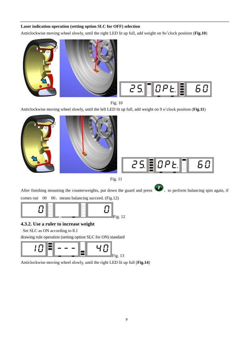
Anticlockwise moving wheel slowly, until the right LED lit up full, add weight on 9o’clock position (Fig.10)
Fig. 10
Anticlockwise moving wheel slowly, until the left LED lit up full, add weight on 9 o’clock position (Fig.11)
Fig. 11
After finishing mounting the counterweights, put down the guard and press ,to perform balancing spin again, if
comes out 00 00,means balancing succeed. (Fig.12)
Fig. 12
4.3.2. Use a ruler to increase weight
Set SLC as ON according to 8.1
drawing rule operation (setting option SLC for ON) standard
Fig. 13
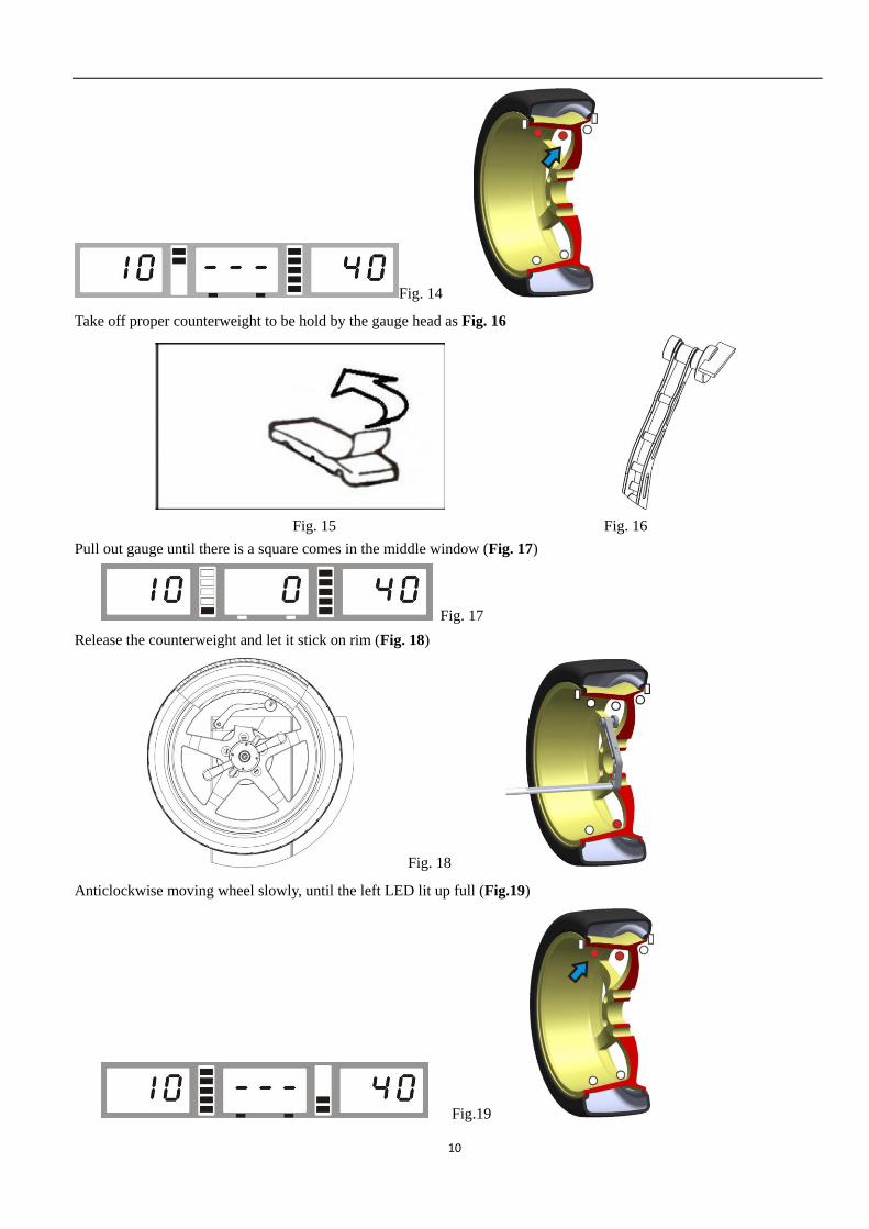
Anticlockwise moving wheel slowly, until the right LED lit up full (Fig.14)
10
Fig. 14
Take off proper counterweight to be hold by the gauge head as Fig. 16
Fig. 15 Fig. 16
Pull out gauge until there is a square comes in the middle window (Fig. 17)
Fig. 17
Release the counterweight and let it stick on rim (Fig. 18)
Fig. 18
Anticlockwise moving wheel slowly, until the left LED lit up full (Fig.19)
Fig.19
11
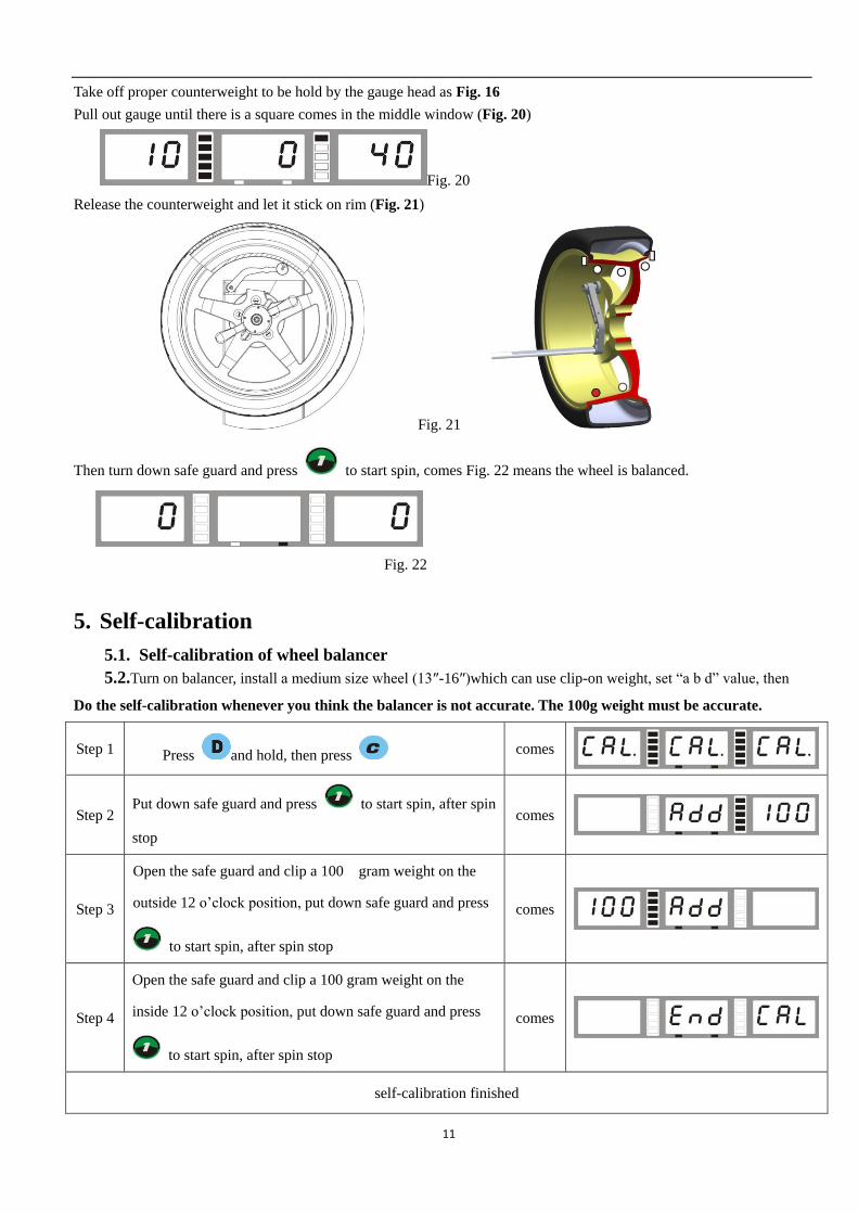
Take off proper counterweight to be hold by the gauge head as Fig. 16
Pull out gauge until there is a square comes in the middle window (Fig. 20)
Fig. 20
Release the counterweight and let it stick on rim (Fig. 21)
Fig. 21
Then turn down safe guard and press to start spin, comes Fig. 22 means the wheel is balanced.
Fig. 22
5. Self-calibration
5.1. Self-calibration of wheel balancer
5.2.Turn on balancer, install a medium size wheel (13″-16″)which can use clip-on weight, set “a b d” value, then
Do the self-calibration whenever you think the balancer is not accurate. The 100g weight must be accurate.
Step 1 Press and hold, then press comes
Step 2 Put down safe guard and press to start spin, after spin
stop
comes
Step 3
Open the safe guard and clip a 100 gram weight on the
outside 12 o’clock position, put down safe guard and press
to start spin, after spin stop
comes
Step 4
Open the safe guard and clip a 100 gram weight on the
inside 12 o’clock position, put down safe guard and press
to start spin, after spin stop
comes
self-calibration finished
12
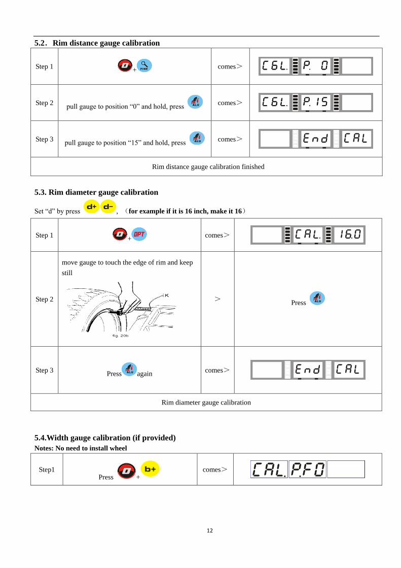
5.2.Rim distance gauge calibration
Step 1 +
comes>
Step 2 pull gauge to position “0” and hold, press
comes>
Step 3 pull gauge to position “15” and hold, press
comes>
Rim distance gauge calibration finished
5.3. Rim diameter gauge calibration
Set “d” by press , (for example if it is 16 inch, make it 16)
Step 1 +
comes>
Step 2
move gauge to touch the edge of rim and keep
still
> Press
Step 3 Press again
comes>
Rim diameter gauge calibration
5.4.Width gauge calibration (if provided)
Notes: No need to install wheel
Step1 Press +
comes>
13
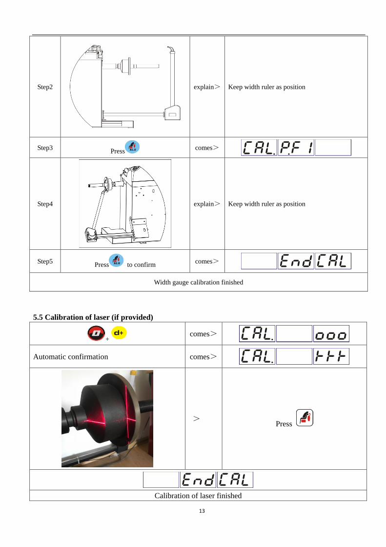
Step2
explain> Keep width ruler as position
Step3 Press
comes>
Step4
explain> Keep width ruler as position
Step5 Press to confirm
comes>
Width gauge calibration finished
5.5 Calibration of laser (if provided)
+ comes>
Automatic confirmation comes>
> Press
Calibration of laser finished
14
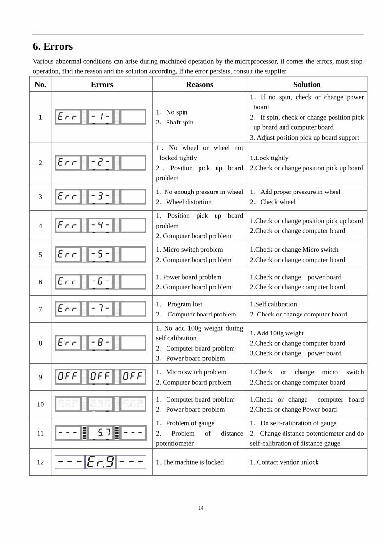
6. Errors
Various abnormal conditions can arise during machined operation by the microprocessor, if comes the errors, must stop
operation, find the reason and the solution according, if the error persists, consult the supplier.
No. Errors Reasons Solution
1
1.No spin
2.Shaft spin
1.If no spin, check or change power
board
2.If spin, check or change position pick
up board and computer board
3. Adjust position pick up board support
2
1 . No wheel or wheel not
locked tightly
2 . Position pick up board
problem
1.Lock tightly
2.Check or change position pick up board
3
1.No enough pressure in wheel
2.Wheel distortion
1.Add proper pressure in wheel
2.Check wheel
4
1. Position pick up board
problem
2. Computer board problem
1.Check or change position pick up board
2.Check or change computer board
5
1. Micro switch problem
2. Computer board problem
1.Check or change Micro switch
2.Check or change computer board
6
1. Power board problem
2. Computer board problem
1.Check or change power board
2.Check or change computer board
7
1. Program lost
2. Computer board problem
1.Self calibration
2. Check or change computer board
8
1. No add 100g weight during
self calibration
2.Computer board problem
3.Power board problem
1. Add 100g weight
2.Check or change computer board
3.Check or change power board
9
1.Micro switch problem
2. Computer board problem
1.Check or change micro switch
2.Check or change computer board
10
1.Computer board problem
2.Power board problem
1.Check or change computer board
2.Check or change Power board
11
1.Problem of gauge
2. Problem of distance
potentiometer
1.Do self-calibration of gauge
2.Change distance potentiometer and do
self-calibration of distance gauge
12
1. The machine is locked 1. Contact vendor unlock
15
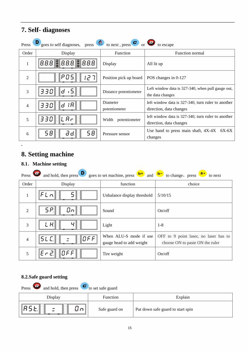
7. Self- diagnoses
Press goes to self diagnoses, press to next , press or to escape
Order Display Function Function normal
1
Display All lit up
2
Position pick up board POS changes in 0-127
3
Distance potentiometer Left window data is 327-340, when pull gauge out,
the data changes
4
Diameter
potentiometer
left window data is 327-340, turn ruler to another
direction, data changes
5
Width potentiometer left window data is 327-340, turn ruler to another
direction, data changes
6
Pressure sensor Use hand to press main shaft, 4X-4X 6X-6X
changes
.
8. Setting machine
8.1.Machine setting
Press and hold, then press goes to set machine, press and to change,press to next
Order Display function choice
1
Unbalance display threshold 5/10/15
2
Sound On/off
3
Light 1-8
4
When ALU-S mode if use
gauge head to add weight
OFF to 9 point laser, no laser has to
choose ON to paste ON the ruler
5
Tire weight On/off
8.2.Safe guard setting
Press and hold, then press to set safe guard
Display Function Explain
Safe guard on Put down safe guard to start spin
16
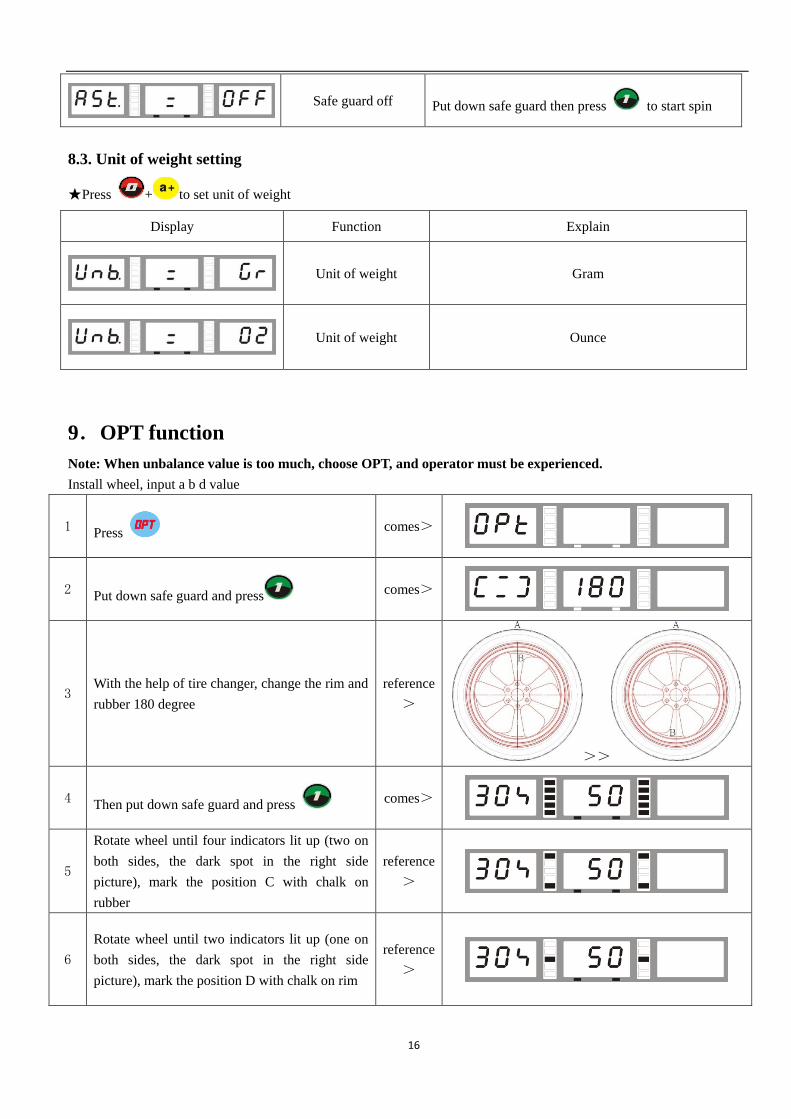
Safe guard off Put down safe guard then press to start spin
8.3. Unit of weight setting
★Press + to set unit of weight
Display Function Explain
Unit of weight Gram
Unit of weight Ounce
9.OPT function
Note: When unbalance value is too much, choose OPT, and operator must be experienced.
Install wheel, input a b d value
1 Press
comes>
2 Put down safe guard and press
comes>
3 With the help of tire changer, change the rim and
rubber 180 degree
reference
>
>>
4 Then put down safe guard and press
comes>
5
Rotate wheel until four indicators lit up (two on
both sides, the dark spot in the right side
picture), mark the position C with chalk on
rubber
reference
>
6
Rotate wheel until two indicators lit up (one on
both sides, the dark spot in the right side
picture), mark the position D with chalk on rim
reference
>
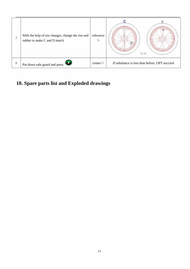
17
7 With the help of tire changer, change the rim and
rubber to make C and D match
reference
>
>>
8 Put down safe guard and press
comes> If unbalance is less than before, OPT succeed
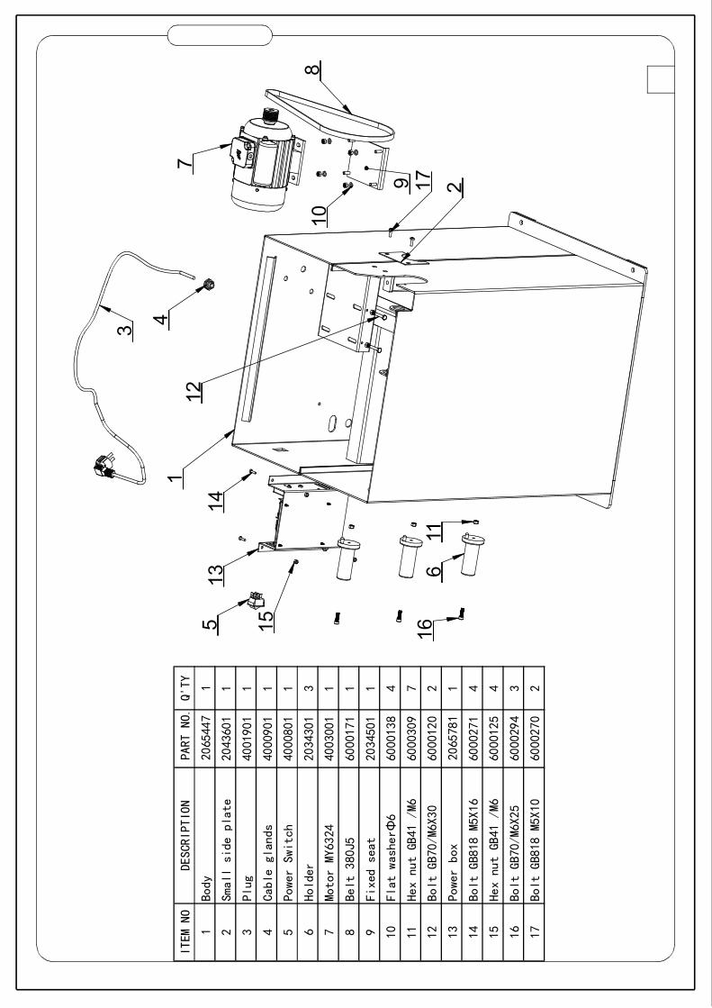
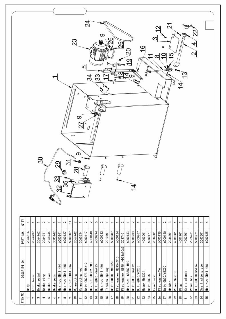
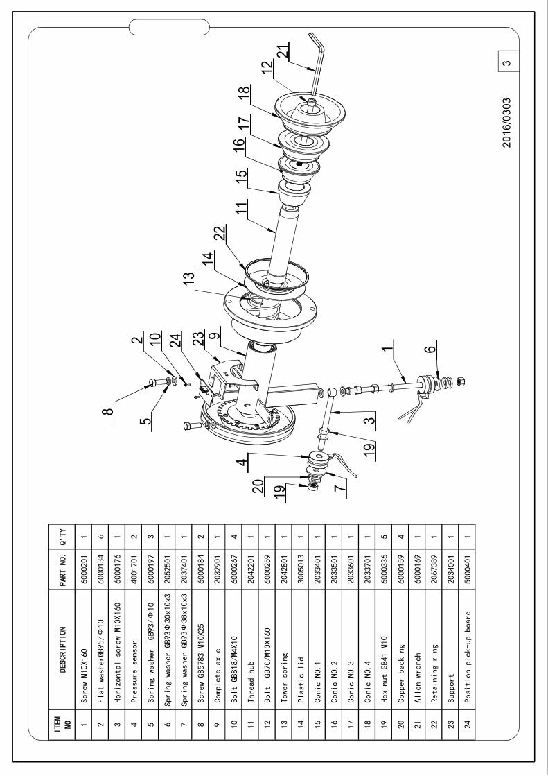
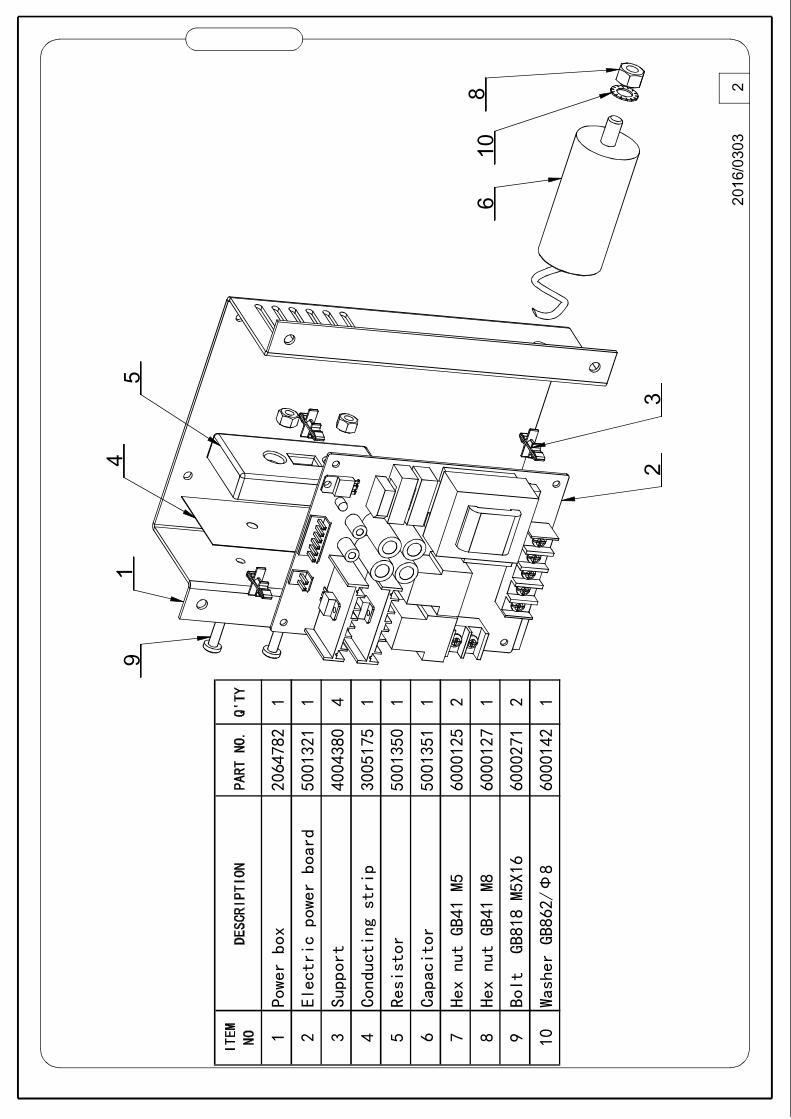
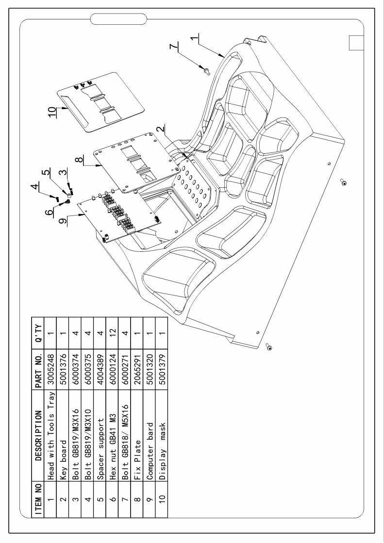
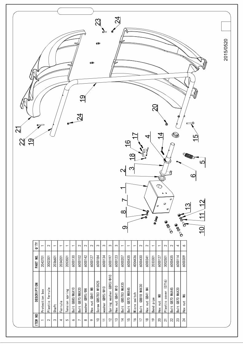
10. Spare parts list and Exploded drawings
12
10
1611
135
14
14
26
7
3
179
15
ITEM
NO
DESCRI
PTIO
NPART
NO.
Q'TY
1Bo
dy20
6544
71
2Sm
allside
plate
204360
11
3Pl
ug40
0190
11
4Ca
bleglan
ds40
0090
11
5Po
werSwit
ch40
0080
11
6Ho
lder
203430
13
7Mo
torMY63
2440
0300
11
8Be
lt380J5
600017
11
9Fi
xedseat
203450
11
10Fl
atwashe
r6
Φ60
0013
84
11He
xnu
tGB
41/M6
600030
97
12Bo
ltGB70/
M6X3
060
0012
02
13Po
werbox
206578
11
14Bo
ltGB818
M5X16
600027
14
15He
xnu
tGB
41/M6
600012
54
16Bo
ltGB70/
M6X2
560
0029
43
17Bo
ltGB818
M5X10
600027
02
8
24
2623
1
30
14
3132
16
33
11
34
10
1920
7
18
35
3 22
14
21
2
12
4
15
29
8
13917
95
289
6
1425
27
9
33
ITEM
NODE
SCRIPTION
PART
NO.
Q'TY
1Bo
dy20
64814
1
2Fo
otlever
2064939
1
3Br
ake
pedal
2064962
1
4Br
ake
ring
2064941
2
5Br
ake
lever
2064944
1
6Br
ake
pads
3005142
1
7He
xnut
GB41/M4
6000341
1
8He
xnut
GB41/M8
6000127
2
9He
xnut
GB41/M6
6000309
11
10Co
nnecting
2064942
2
11Co
nnecting
rod
2065534
1
12Bo
ltGB2673
M6X12
6000417
2
13He
xnut
GB889
/M8
6000148
2
14Bo
ltGB70/M6X25
6000294
6
15He
xnut
GB41/M6
6000233
2
16Te
nsion
spring
2010701
1
17Bo
ltGBT70
M10X60
6000289
1
18Fl
atwasher
GB95/
10Ф
6000134
1
19Fl
atwasher
GB95
/38x10x3
Φ20
37401
2
20He
xnut
GB889
M10
6000143
1
21Bo
ltGB80
M6X12
6000230
2
22Bo
ltGB70/M6X35
6000207
1
23Mo
tor
MY6324
4003001
1
24Be
lt380J5
6000171
1
25Fi
xed
seat
2034501
1
26Fl
atwasher
6Φ
6000138
4
27Bo
ltGB70/M6X30
6000120
2
28Ho
lder
2034301
3
29Po
wer
Switch
4000801
1
30Pl
ug40
01901
1
31Ca
ble
glands
4002201
1
32Po
wer
box
2065781
1
33Bo
ltGB818
M5X16
6000271
4
34Sm
all
side
plate
2043601
1
35He
xnut
GB41/M6
6000125
4
2016/0303
3
2011
1517
1812
21
224
23 9
5
19
2
19
13
7
3
14
8
24 1 6
16
10
1ScrewM10X160
6000201
1
2Flat
washerGB95
10
/Ф6000134
6
3Horizontal
screwM10X160
6000176
1
4Pressure
sensor
4001701
2
5Spring
washer
GB93
10
/Ф
6000197
3
6Spring
washer
GB93
30x10x3
Φ2052501
1
7Spring
washer
GB93
38x10x3
Ф2037401
1
8ScrewGB5783
M10X25
6000184
2
9Complete
axle
2032901
1
10Bolt
GB818M4X10
/
6000267
4
11Thread
hub
2042201
1
12Bolt
GB70
M10X160
/
6000259
1
13Towerspring
2042801
1
14Plasticlid
3005013
1
15ConicNO
1
.2033401
1
16ConicNO
2
.2033501
1
17ConicNO
3
.2033601
1
18ConicNO
4
.2033701
1
19HexnutGB41
M10
6000336
5
20Copper
backing
6000159
4
21Allenwrench
6000169
1
22Retainingring
2067389
1
23Support
2034001
1
24Position
pick
upboard
-
5000401
1
2016/0303
91
45
68
10
32
2
1Po
werbo
x
2064
782
1
2El
ectr
icpo
werbo
ard
5001
321
1
3Su
ppor
t4004
380
4
4Co
nduc
ting
stri
p
3005
175
1
5Re
sist
or5001
350
1
6Ca
paci
tor
5001
351
1
7He
xnu
tGB
41M5
6000
125
2
8He
xnu
tGB
41M8
6000
127
1
9Bo
ltGB
818M5
X16
6000
271
2
10Wa
sher
GB86
28
/Ф
6000
142
1
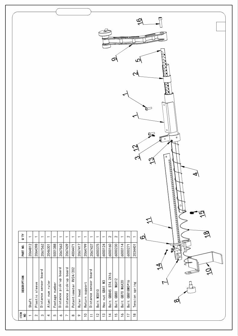
1Sh
aft
2064
812
1
2Pl
asti
csl
eev
e20
6439
81
3Di
stan
cese
nsor
boar
d20
6756
21
4Al
umi
num
rul
er20
4630
11
5Fo
otag
enu
mbe
r50
0138
81
6Di
stan
cepi
ckup
boa
rd-
2067
563
1
7Di
stan
cepi
ckup
boa
rd-
2067
439
1
8Po
tent
iome
ter
RV24
202
/40
0447
11
9Ru
ler
head
2067
417
1
10Re
turn
supp
ort
2064
799
1
11Di
stan
cese
nsor
boar
d20
6743
71
12Bo
ltM3
X10
6000
375
1
13He
xnu
tGB
41
M360
0012
41
14Bo
ltGB
845
ST4
2X16
.60
0016
02
15Bo
ltGB
80M6
X12
6000
230
2
16Bo
ltGB
70M6X
2060
0011
41
17Bo
ltGB
818M
516*
6000
271
2
18Te
nsio
nsp
rin
g20
3440
11
2
10
89
45 3
6
1
7
1Hea
dwith
Tools
Tray
3005248
1
2Key
board
5001376
1
3Bol
tGB819/M3X16
6000374
4
4Bol
tGB819/M3X10
6000375
4
5Spa
cersupport
4004389
4
6Hex
nut
GB41M3
6000124
12
7Bol
tGB818/
M5X16
6000271
4
8Fix
Plate
2065291
1
9Com
puterbard
5001320
1
10
Dis
play
mask
5001379
1
13 125
163
4
6
79
8
1011
15
2
23
1
1718
1924
19
2122
20
24
14
2015/0520
1Protection
box
204370
11
2Plasticferr
ule
300230
12
3Shaft
203660
11
4Ferrule
203420
11
5Tensionspri
ng20
5350
11
6Bolt
GB80/M
6X10
600013
01
7Bolt
GB70/M
8X20
600010
22
8washer
GB95
/8Ф
600014
22
9HexnutGB41
M860
0012
72
10ScrewGB5783
M10X25
600018
43
11washer
GB95
/10Ф
600013
43
12Spring
wash
erGB
93/
10Ф
600019
73
13HexnutGB41
M10
600012
33
14Bolt
GB5783
M6X35
600020
71
15Bolt
GB70
M8X45
600043
51
16Microswitch
400443
61
17Bolt
GB818
M4X3
060
0043
02
18HexnutGB41
M460
0034
12
19Bend
pipe
203330
11
20Hexnut
M860
0012
71
21Plasticcove
r(0
716)
300250
12
22Bolt
GB70
M6X45
600043
52
23Bolt
GB70
M6X20
600011
44
24Hexnut
M660
0030
96
54
812
1011
6
9
2
3
17
13
13