Embed Size (px)
DESCRIPTION
Wheel Alignment Service. Chapter 68. Objectives. Perform a prealignment inspection of the steering and suspension Describe how to adjust caster, camber, and toe Understand the different ways of adjusting wheel alignment angles. Introduction. Steering and suspension - PowerPoint PPT Presentation
Citation preview
© 2012 Delmar, Cengage Learning
Wheel Alignment Service
Chapter 68
© 2012 Delmar, Cengage Learning
Objectives• Perform a prealignment inspection of the
steering and suspension• Describe how to adjust caster, camber, and toe• Understand the different ways of adjusting
wheel alignment angles
© 2012 Delmar, Cengage Learning
Introduction• Steering and suspension
– Inspect before aligning wheels
– Loose parts prevent accurate and lasting adjustment
• Wheel alignment – Requested because of unusual tire wear and/or
handling problems
– Front axles experience more stress
© 2012 Delmar, Cengage Learning
Prealignment Inspection• Parts are loose or worn
– Alignment will not be successful
• Important considerations– Tire pressure must be adjusted
– Vehicle ride height must be correct
– Worn bushings must not allow movement of suspension and steering parts
– Steering gear and linkage coupling points must not have excessive clearance
– Tires must be new or worn evenly
© 2012 Delmar, Cengage Learning
Tire Wear Inspection and Ride Height Check
• Tire wear inspection– Wear from incorrect camber shows on outside or
inside of tire tread
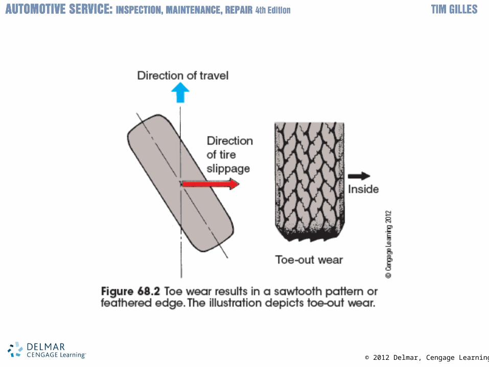
– Driving a vehicle with excessive toe is dangerous because front tires slide
– RWD cars with radial tires toe-in will roll under
• Ride height check– Specifications assume ride height is correct
– Check ride height prior to wheel alignment
© 2012 Delmar, Cengage Learning
© 2012 Delmar, Cengage Learning
Toe Change• Suspension height changes: toe measurement
changes – Example: springs sag
• Toe change causes tire scrub on road surface– Wears away tread
• Toe change confined to one side of vehicle– Bump steer can result
© 2012 Delmar, Cengage Learning
Torque Steer• Vehicle turns abruptly to side during initial
acceleration– Found on front-wheel-drive cars with axles of
unequal lengths
– Results in unequal CV joint angles
– Could be due to loose sub-frame or problem with unequal spring height
© 2012 Delmar, Cengage Learning
Suspension Looseness• “You can't align looseness”
– Perform a dry park check for steering and suspension looseness
• Linkages in good condition will allow pivoting only• Any slack between parts will become apparent
due to the resistance of the tires• Always check adjustment of wheel bearings
© 2012 Delmar, Cengage Learning
Test Drive• Test drive before performing repairs
– Unless vehicle is unsafe
• Perform visual inspection before driving– Suspension bushings
– Steering linkage pivot connections
– Rubber grease boots on tie-rod ends and ball joints
– Shock absorbers
© 2012 Delmar, Cengage Learning
Tire Checks and Inspection Checklist
• Perform a tire check and power steering check– Sometimes pull results from the crown of the
road surface
– Before attempting wheel alignment: check for looseness in any related parts
– Test ball joints for looseness
• Inspection checklist– Used by technicians to make sure no steps are
accidentally forgotten
© 2012 Delmar, Cengage Learning
Wheel Alignment Procedures• Front suspension: designed to keep wheels in
best possible position when rolling• Alignment settings change
– Vehicle speed
– Roughness of road surface
– Acceleration and braking
– Weight distribution and cornering
• Adjustments to original settings may be needed– Adjustable angles: caster, camber, and toe
© 2012 Delmar, Cengage Learning
Measuring Alignment• Alignment measurements
– Read in degrees and parts of degrees
• Important considerations– Slip plates are under the rear tires
– Front wheels are positioned on radius plates
– Computerized alignment machines do four-wheel alignment inspection
– Vehicle must be level to get accurate measurements
– Toe is adjusted last
© 2012 Delmar, Cengage Learning
Measuring Camber and Measuring Caster
• Camber– Comparison measurement to true vertical, using
a level• Position wheels straight ahead while reading
gauge
• Caster – Causes camber angle to change during a turn
• Wheel is turned either inward or outward a specified amount
© 2012 Delmar, Cengage Learning
Road Crown and Pull• Roads are crowned so rain with run off• Methods to compensate for road crown
– Camber set slightly more positive on driver's side
– Caster set slightly more negative on driver's side
• SLA suspensions – Camber adjustment is done with shims,
eccentrics, or movement in elongated slots
© 2012 Delmar, Cengage Learning
Road Crown and Pull (cont’d.)• When there are shims, caster and camber are
changed together– Shims have the opposite effect as the normal
control arm
• Other adjustment methods– Some vehicles use an electric cam adjustment
on the upper or lower control arm, or strut
– Several other less common adjustments
© 2012 Delmar, Cengage Learning
Measuring Steering Axis Inclination
• SAI does not change– Not adjustable
• Change in SAI occurs if:– The spindle has been bent
– There is body damage resulting in a bent strut tower
• Cradle has shifted to one side– Camber will change on both front wheels
• Included angle – Amount of SAI minus camber
© 2012 Delmar, Cengage Learning
Measuring Toe• Check and adjust toe after replacing steering
linkage component– Distances between fronts and rears of front tires
are compared
– Traditionally measured as a distance in inches or millimeters
• Recent trend is to measure the toe angle
• FWD and RWD vehicles – Different toe specifications
© 2012 Delmar, Cengage Learning
Adjusting Toe• Steering linkages on most vehicles
– Have either two or four tie-rod ends• Shortening or lengthening changes toe setting
• Major steps– Center the steering wheel and hold it in place
– Make adjustments
– Position clamp properly and tighten
• Rack-and-pinion steering systems – Have an outer tie-rod and inner tie-rod end with a
jam nut on each side
© 2012 Delmar, Cengage Learning
Centering a Steering Wheel• Steps to straighten wheel
– Count the number of turns of the steering wheel while turning it from lock to lock
– Position steering wheel so that it is half-way between the locks
– Use a steering wheel holder to keep the steering wheel centered while adjusting
– Correct toe after a test drive
© 2012 Delmar, Cengage Learning
Checking for Toe Change• Sometimes toe only remains as set when the
vehicle is at the correct ride height– Should be checked during wheel alignment
• Rack-and-pinion steering gear mounted in non-level position– Tie rod will be at unequal angles
• Some vehicles use shims to adjust rack-and-pinion height to correct for toe change
© 2012 Delmar, Cengage Learning
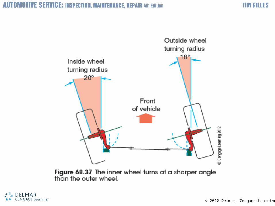
Measuring Turning Radius• Observe the pointer on the radius plate while
making a caster measurement– Ackerman Angle
• Steering arms are angled to point to the center of the rear axle
– Turning radius is not an adjustable angle
© 2012 Delmar, Cengage Learning
© 2012 Delmar, Cengage Learning
General Wheel Alignment Rules• Caster/camber
– Vehicle pulls to side: negative caster and positive camber
• Adjusting for negative caster yields easier steering
– Driver’s weight will cause camber to increase on left front wheel and decrease on right front wheel
– Shim adjustment on SLA suspension• Changing camber will not affect caster• Changing caster will affect camber
© 2012 Delmar, Cengage Learning
General Wheel Alignment Rules (cont’d.)
– Caster for both wheels should be set either positive or negative
– Caster spread between front wheel settings should not be more than ½ degree
– Make caster equal from side to side
– Power steering vehicles can have caster as high as ten degrees
– Macpherson strut vehicle: jounce while measuring camber
– Toe adjustment has the most impact on tire wear
© 2012 Delmar, Cengage Learning
Four Wheel Alignment and Performing Four-Wheel Alignment
• Important considerations– Geometric centerline: line drawn between center
of front axle and center of rear axle
– Thrustline: direction rear wheels point
– Thrust angle: formed by thrustline and geometric centerline
– During computer wheel alignment: sensors are installed on all four wheels
– Thrust angle is same as geometric centerline: steering wheel will be correctly centered
© 2012 Delmar, Cengage Learning
Compensating the Alignment Heads and Measuring Caster and Camber
• Machines with targets automatically compensate the alignment heads– Many older machines require higher level of skill
• Machines today are quicker and easier
• Amount of wheel sweep during a caster check is determined by the alignment program– Wheels have been positioned correctly:
alignment readings are displayed
© 2012 Delmar, Cengage Learning
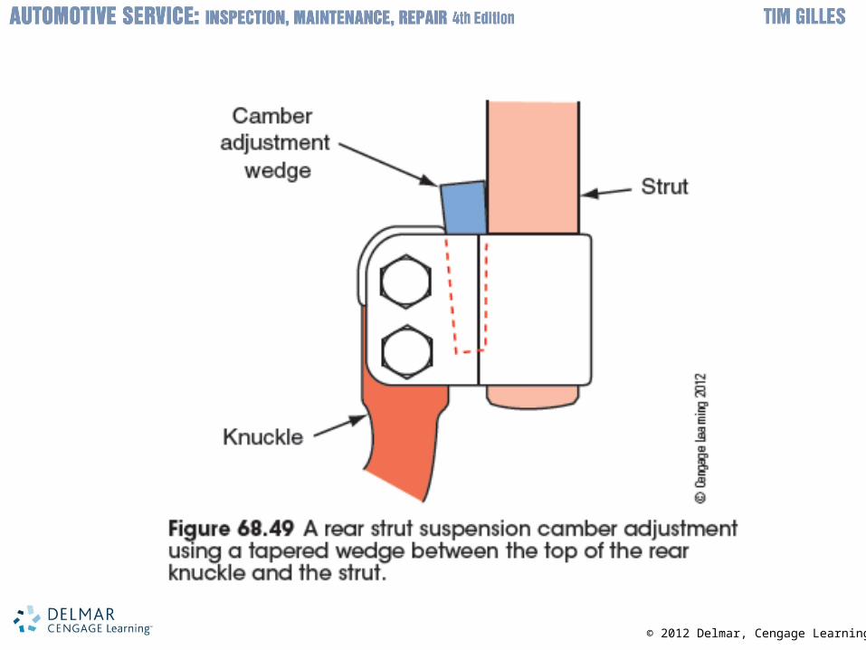
Adjusting Rear-Wheel Alignment• Camber and toe adjustments
– Possible on some vehicles• Camber adjustment on double wishbone rear
suspension: done by turning eccentric adjuster
• Rear-wheel toe – Can be adjusted in several ways
• Wheel alignment rules– No heavy loads in vehicle
– Fuel tank should be full
– Vehicle is aligned in condition it’s normally driven
© 2012 Delmar, Cengage Learning