Embed Size (px)
Citation preview

1
What's New in OMEGA 2.5.1
GERBER OMEGA 2.5.1 includes several new features for improving design and workflow. Use this document as an addendum to the OMEGA 2.5 Reference Manual.
R
CQ
N
N
O
Note: OMEGA 2.5.1 is compatible with Windows® 2000 and Windows XP. OMEGA 2.5.1 is not tested or supported for use with Windows ME, Windows 95 and 98, and Windows NT 4.0. See Getting Started with OMEGA 2.5.1 for detailed hardware and software requirements.
eview this document and see OMEGA Help for details on using these exciting features!
ontents uick List .......................................................................................................................................2 ew in Composer ........................................................................................................................6 New Features and Enhancements .........................................................................................................6
Flipping images.....................................................................................................................................6 Rotating images.....................................................................................................................................6 Flipping gradient fills...........................................................................................................................7 Creating a surround shape ..................................................................................................................7 Generating Decal Cuts includes cut lines and/or clipping paths..................................................8 Global stroke width editing.................................................................................................................9
Menus and Functionality ......................................................................................................................10 Enhanced Job Palette ..........................................................................................................................10 Tools commands available in the context menu.............................................................................11
Import/Export Enhancements.............................................................................................................13 Dimensioning Enhancements ..............................................................................................................15 Layers Enhancements............................................................................................................................16 Text and Language tools.......................................................................................................................18
ew in GSPPlot ......................................................................................................................... 19 New Features and Enhancements .......................................................................................................19
Output Job Settings in GSPPlot.........................................................................................................19 USB-to-Parallel Option for the GERBER EDGE/EDGE 2 .............................................................20
Menus and Functionality ......................................................................................................................21 Outputting multiple layers for printing (or spool file) ..................................................................21 Viewing and changing the heat setting of a foil .............................................................................21
ther General Enhancements................................................................................................ 23

2
Quick List
♦ PLT files that contain images will have a smaller file size due to compressed thumbnails of images that display on-screen. (Compression of 24-bit thumbnails occurs automatically.)
♦ Enhanced Job Palette contains vinyls, spot foils, GerberColor Spectratone foils, and process foils. (View > Job Palette > Show Job Palette.)
♦ All OMEGA palettes include a “dot denotation” within the color swatch to show if a color is spot, process, vinyl or GerberColor Spectratone. (View any color palette in OMEGA to see the dots.)
♦ Flip images. (Select an image, Shape > Flip X/Flip Y, etc…)
♦ Rotate images in one-degree increments. (Select an image, Shape > Directed Rotate or Keyboard Rotate, or use the work surface rotate tool for free rotation.)
♦ Automatically flip gradient fills. (Occurs automatically when vector objects with gradient fills are flipped.)
♦ New Paste Here and Import cursors locate the upper left corner of the pasted or imported files at the mouse location, allowing for more precise positional control. (Right click the work surface for Paste Here command, and File > Import to import files.)
♦ Access Outline, Distortion, Warp, Shadow, and Effects commands from the context (right-click) menu. (Select objects and right click to display the menu.)
♦ Dimension improvements include new default sizes for dimension objects, the ability to size arrowheads without changing size of other dimension objects, easy selection of dimension objects via the Select menu, and the option to paper print dimension objects. (Arrowhead sizing is available on the right side of the Dimension Property Bar when a dimension tool is active. Selection is available via Select > Dimension > choose dimension type. Paper printing of dimension objects is available via File>Print>then choose the Options tab.)
♦ Quickly layout a sign by creating a Surround shape at a designated distance from selected objects. (Select objects to be surrounded > Tools > Surround, Extract Image Paths > Surround.)
♦ Globally edit stroke widths of multiple objects. (Select objects with strokes > Tools > Edit Stroke Width.)

3
♦ Decal Cut dialog box now generates cut lines, clipping paths or both cut lines and clipping paths for images and vector objects. (Select objects, Tools > Generate Decal Cut.)
♦ Decal cut allows for the setting of a white-point threshold in images, reducing the incidence of generating a decal cut that is a square or rectangle. (Select an image, Tools > Generate Decal Cut and set White Threshold.)
♦ Save files backward to OMEGA 2.5, 2.1, 2.0, 1.56, or GRAPHIX ADVANTAGE 6.2. (File > Save As > Choose PLT format.)
♦ Instead of giving a message about resampling images to one-bit per pixel, Composer automatically determines whether to use Posterize Image/Color Raster to Vector or Raster to Vector (for monochrome images) depending on type of image selected. (Select an image, Tools > Raster to Vector or Posterize Image/Color Raster to Vector.)
♦ Import or extract image paths from JPEG, PSD, or TIF files. (Import an image, Tools > Surround, Extract Image Paths…)
♦ OMEGA automatically offers the use of a second AI or EPS import filter if no results are produced from the use of the first import filter. (File > Import > select an EPS or AI file. If the import is unsuccessful another filter will be offered.)
♦ Export raster files (BMP, JPG, TIF, or GIF) to a fixed size in pixels. (File > Export > Choose BMP, TIF, JPG file > Turn on Fixed Size from the Export Options dialog box.)
♦ Export to AI or EPS while maintaining PANTONE® or Gerber process color names (Create a file with PANTONE or other named colors: File > Export > Choose EPS (GSP) or AI (GSP) filter > Turn on Preserve Process Color Names in the Export Options dialog box.)
♦ Enhanced Layer Tree performance improves the opening, redraw, and selection of files with many objects. Turning off the Layer Tree further speeds working with jobs that contain many objects.
♦ Improved Layer Tree Lock/Unlock and Show/Hide icons make it harder to accidentally lock or hide layers.
♦ Select the entire group or combine in Layer Tree when selecting one member of the group or combine. (Select grouped or combined objects in the Layer Tree with the Shape or Color selection pointer.)
♦ Move To or Copy To commands in the Layer Tree context menu allows you to place objects (or copies of objects) on an existing layer or on a newly created layer. (Select one or more objects and right click to display context menu. Choose Move To or Copy To and the layer on which to place the objects.)

4
♦ Paste Back In Back Of and Paste Back In Front Of commands are available in the context (right-click) menu of the Layer Tree.
♦ Right-click on objects in the Layer Tree to access and use Shape Menu commands: Rotate, Size, Move, Slant, or Flip.
♦ Double click on objects in the Layer Tree to perform smart edits on those objects. Double click with the Color pointer to access Fill attributes, or double click with the Shape pointer to access smart edit properties (if available).
♦ Display the vinyl, fill, and stroke properties of objects in the Layer Tree. (Click Layer Menu > Object Properties > Choose properties to display.)
♦ Select Locked Layers command selects all layers that are currently locked in the job. You can then hide, delete, or unlock them. (Click Layer Menu > Select Locked Layers.)
♦ Bitmap fonts are available in Small Text but are not recommended for output to the GERBER EDGE series printers. (Open Enter/Edit Small Text > Font Select and the fonts display in the Font dialog box.)
♦ Updated Spell Check includes multiple languages and custom user dictionaries. (Available from TOWS or either of the Enter/Edit Text dialog boxes.)
♦ Arabic language Text Entry support. The Arabic Font Pack is installed from the OMEGA Font & Library CD. (Available in the Enter/Edit Text and Enter/Edit Small Text dialog boxes once Arabic is enabled in Windows and in Tools > Options > Text.)
♦ The In Front Of or In Back Of commands can be canceled with the Esc key or the End In Front Of or End In Back Of command. (Arrange Menu > In Front Of / In Back Of.)
♦ Status bar displays fill percentage for tints including GerberColor Spectratone.
♦ Directed Rotate dialog box allows you to select a rotation handle instead of clicking a rotation point on the desktop.
♦ Set a default process palette on the revised Tools > Options > Palettes tab (previously the Vinyl tab).
♦ An Updated GerberColor Spectratone palette includes all spot color combinations including Traffic Gray and Vivd Blue, and all GerberColor Spectratone colors have been remeasured. (Used automatically in OMEGA 2.5.1.)
♦ Document properties reflect embedded or linked image state and location of image file. (File > Properties > Images. If path is a temp location, image is embedded.)
♦ Print Job Settings in the unused margin before EDGE prints. (Open a job to be printed on the EDGE, In GSPPlot, Setup > Print Options > Turn on Output Job Settings.)

5
♦ Revised Select Colors dialog box in GSPPlot allows for all layers to be output at the same time, or to be output to a single spool file. In OMEGA 2.5, each layer of a layered job had to be output separately. This feature outputs all layers with a single click. (Open a layered job in GSPPlot, Setup > Select Colors > Turn on Output By Layer, Under Layers to Output choose All Selected Layers.)
♦ View or change the foil heat settings from Normal heat to overprint (Hot) heat or overprint to Normal for GerberColor foils in the GSPPlot Print Options dialog box. This does not change the foil knockouts for a job. This can be useful when reversing print and the need arises to adjust the print energy for certain colors. (Open a job to be printed on the EDGE, Setup > Print Options, click right on a foil color in the Foil Color list and choose Heat > select the new heat setting)
♦ Control which Foil List columns to display in the GSPPlot Print Options dialog box. (Open a job to be printed on the EDGE, Setup > Print Options, click right on a foil color in the Foil Color list, choose View… > Options > select the columns to view. Can also be access from Tools > Options > Foil Info.)
♦ USB-to-Parallel connectivity for the GERBER EDGE and GERBER EDGE 2. Available as a Gerber cable option for the EDGE 2, or as an off-the-shelf cable for the EDGE 1.)
♦ Print compatible targets for Graphtec type 2 plotters. (In GSPPlot, install a Graphtec FC-7000 plotter. Open a job to be printed and cut, Setup > Print Options > Choose Targets… > Select 4 corners > Turn on Graphtec Type 2.)
♦ Most router RTP files created in OMEGA 2.5.1 are backward compatible with previous versions of ART Path (OMEGA 2.0 through 2.5). If there are shapes in the job which contain too many data points in the tool path, a message displays and the shapes are not included in the older format file.
♦ Note to existing Gerber ImageRIP customers: Gerber ImageRIP (not ImageRIP Pro or Plus by Onyx) does not support rotated or flipped images. (Gerber ImageRIP is no longer available for purchase.)
♦ MonacoEZcolor is included as the color profile generator for new OMEGA CP kits only. MonacoEZcolor is no longer included with OMEGA CS.

6
New in Composer
New Features and Enhancements Flipping images You can now flip imported images using the Flip X, Flip Y, or Flip Both commands in the Shape menu.
Rotating images You can rotate images using the standard Composer rotate tools including Directed Rotate, Keyboard Rotate, and visually rotating on the work surface.
If you wish to crop an image, you must crop it before rotating it. After rotation the Crop Image tool is not available. When possible, rotated images are maintained when using the GSP AI and EPS import and export filters.
To dramatically increase on screen drawing times, slight changes in on-screen coloration also might occur to rotated images as rotated images are not color corrected for on screen viewing. Rotated images are color corrected for EDGE and MAXX 2 output purposes.

7
Flipping gradient fills When flipping vector shapes with gradient fills, the gradient fill automatically flips with the object. You no longer have to manually update the gradient fill.
Creating a surround shape Quickly create a balanced sign by selecting one or more objects and using the Surround command to create a box around the perimeter of the selected objects. To access the Surround command click Tools > Surround, Extract image paths… to open the Option Selection dialog box. Choose the Surround option.
In the Create Surround Shape dialog box, enter a value in the Margin box to designate the surround shape distance from the selected objects. Turn on Apply current style to create the box using the currently active vinyl, fill and stroke. Turn on Include stroke widths to calculate the placement of the surround shape taking into consideration any strokes on the selected objects.
Surround shape

8
Generating Decal Cuts includes cut lines and/or clipping paths Generate Decal Cut will create a cut line and/or a clipping path around images or vector shapes in Composer. If you view a design in Filled Mode (F8) and draw an imaginary line around the filled objects on screen; that will give you an idea of what the decal cut will look like. When viewing images in filled mode, if you see a white color, Generate Decal Cut will place a cut line and/or Clipping Path around it.
Select the image or vector shape which will have a Decal Cut and choose Tools > Generate Decal Cut to open the Decal Cut dialog box. Depending on whether the selected object is an image or vector shape the Decal Cut dialog box varies.
Decal Cut for Images Decal Cut for Vector Shapes
When using Generate Decal Cut with images, the clipping path or cut line is placed around the non-white areas of the image. All colors are considered non-white and pure white is considered "white." In some cases, a background area of an image that appears white to the eye may actually be gray or off-white, so you might get a cut line or clipping path around that area. The White Threshold slider provides control over which areas of the image are considered “white.” Slide the control toward More to force more colors to be considered “non-white.” Slide the control toward Less to reduce the colors that are considered “non-white.”
In the previous examples setting the White Threshold toward Less will result in a closer cut line (or clipping path) around the heart as the beige background color is interpreted as “white.” In addition, this setting also creates small cut shapes on the chocolates which will need to be deleted. Setting the White Threshold to More will reduce the extraneous cut lines, but produce a less accurate Decal Cut around the heart. Setting the White Threshold to yield the best Decal Cut results requires some experimentation.

9
Global stroke width editing The Stroke Width Edit command in the Tools menu opens the Global Stroke Width Edit dialog box where you can edit all stroke widths of selected objects. You can edit a stroke size directly by changing the value in the New column. You can also scale all the selected strokes by a specific percentage and clicking the Scale button. All selected objects with that size stroke, regardless of color, will be changed to the new width setting.
s
Original Stroke Width Strokes Scaled to 2.00
10
Menus and Functionality Enhanced Job Palette The new Job Palette contains swatches for vinyls, spot foils, process foils, and GerberColor Spectratone foils that are used in the job. Swatches within the color type display from left to right (or top to bottom if the palette is vertically docked) in the order they are used in the job.
As you add, remove, or change the order of vinyl or foil colors in your job, the job palette automatically updates so it is not necessary to continually press the Refresh button.
Color swatches are labeled as follows:
♦ Vinyl swatch – dot in upper left corner
♦ Spot foil swatch – dot in lower right corner
♦ Spectratone swatch – dot in upper right corner
♦ Process foil swatch – no dot
Note: As you add to or remove vinyl or foil colors from your job the job palette automatically
updates. The two exceptions are: when entering text in TOWS – the palette is updated upon the next carriage return, or when digitizing – the palette is updated when a shape is ended.Status bar displays tint percentages The status bar now displays the tint percentages for fill colors including GerberColor Spectratone tints. The percentage displays before the foil color name or the Spectratone foil short name as shown in the following illustration.
Paste Here cursor A new Paste Here cursor provides greater control of the location of clipboard contents on the Composer work surface. Right click and then choose Paste Here to paste the information at a specific location. A Paste Here cursor displays. Left click with the cursor and the information is placed on the work surface with the upper left corner at the cursor location.
Import cursor When importing files the import cursor displays to allow you to select the import location. Click the cursor on the work surface to import the upper left corner of the file to that location.

11
Tools commands available in the context menu You can access many of the Tools menu commands (Outline, Distortion, Warp, Shadow, and Effects) by selecting an object and right-clicking to display the context menu.
Directed Rotate allows handle selection The Directed Rotate dialog box now allows you to select an object handle as the rotation point in addition to clicking the desktop to set the rotation point.
Automatic selection of Posterize Image to Vinyls or Raster to Vector When you choose one of the commands to convert an image to cut (vector) shapes, Composer automatically determines what type of image it is (black and white or color) and opens the correct dialog box.
For instance, if you select a black and white image and attempt to use Posterize Image/Color Raster to Vector, Composer automatically opens Raster to Vector for monochrome images instead. Conversely, if you select a color image and choose Raster to Vector, Composer automatically displays the Posterize Image to Vinyls dialog box. This eliminates error messages about “Resampling images to 1 bit per pixel” and “Using Color Images.”
Escape from the In Front Of or In Back Of commands The In Front Of or In Back Of commands in the Arrange menu or Arrange Toolbar allows you to move the selected object to a different location on the work surface. Selecting one of the commands turns the cursor into a target arrow. Click a target object on the work surface and the selected object is moved in front of or in back of it in the stacking order.
To escape the command without moving an object, press the Esc key, reselect the command from the Arrange menu to clear the check mark, or right click and select End In Front of (or In Back of) command.
Save OMEGA 2.5.1 files to earlier versions of OMEGA or GA Save files backward to OMEGA 2.5, 2.1, 2.0, 1.56, or GRAPHIX ADVANTAGE 6.2. (File > Save As > Choose PLT format.)

12
Set default Process palette in Tools > Options > Palettes tab The Tools > Options Vinyl tab has been updated and renamed to the Palettes tab. You can now choose a default process palette to display on the Composer work surface from the drop down list. You can select from standard Gerber process palettes or any custom process palettes that you have created.
Viewing document properties The Document Properties dialog box in Composer (File > Properties) and the Job Information tab of the Windows Properties dialog box now display the embedded or linked state of any images in the plot file. The path of the image is also shown.

13
Import/Export Enhancements Importing image paths When importing an image file (JPEG, PSD, or TIF) that contains a working path, saved path, or clipping path the Import Paths from Image dialog box displays. Choose one or more path types to import.
After the image file (JPEG, PSD, or TIF) which contains a working path, saved path, or clipping path imports into Composer, you can extract the path using the Surround, Extract Image Paths… command in the Tools menu.
Automatically try a different AI (GSP) or EPS (GSP) import filter If AI or EPS file fails to import when using either the GSP 2.5 as Vectors filter or the GSP 2.1 as Vectors filter, OMEGA will automatically offer to try importing the file again and displays the following message:
Choosing Yes displays the alternate filter name that will be used when importing.
This automatic import is only available for the following AI or EPS filters:
♦ AI 1.1 thru 8 – (GSP 2.1) as Vectors
♦ AI 7 thru CS – (GSP 2.5) as Vectors
♦ EPS – (GSP 2.1) EPS as Vectors
♦ EPS – (GSP 2.5) EPS as Vectors

14
Exporting Raster files to a Fixed Size When exporting files as BMP, TIF, GIF, or JPG you can now specify the size of the file in pixels. Turn on Fixed Size in the Export Options dialog box. Enter a Width and Height. If you turn on Maintain Aspect Ratio and enter either a height or width, the original proportions of the image are maintained. This feature is useful for providing small-scale customer proofs via email.
Preserving Process Color Names when exporting When exporting to an AI or EPS file using the AI – (GSP) Adobe® Illustrator® File or EPS – (GSP) Encapsulated Postscript filters, you can preserve process color names. Turn on Preserve Process Color Names to maintain named Gerber process colors (such as Raspberry or Peacock Blue) and/or PANTONE® color names (such as PANTONE® 114 C or PANTONE® 2587 C) when exporting. When you open the exported file in Adobe Illustrator or other design programs the names are maintained and appear on the color swatches. These colors can also be used by ImageRIP™ Pro or Plus by Onyx to create more accurate spot color representations through the use of spot color tables that are provided by GSP. Spot color names are also preserved via export by checking the Explicit Tints checkbox when exporting.
Click here to preserve named process colors when exporting
Click here to preserve named spot colors when exporting

15
Dimensioning Enhancements Dimensioning defaults updated The new default size of arrowheads is 1.0"/25.4mm and the new default size of text is 0.8"/20.32mm.
Dimension Arrowhead Sizing Percentage
The Arrowhead Sizing Percentage box controls the size of the arrowheads separately from all other dimension components. The default size is 100% (1.0"/25.4mm). Each click of the up/down arrows increases or decreases the sizing by 20%. If there is a dimension selected the sizing is applied to the selected arrowheads. If no dimension is selected the sizing applies to the next dimension created.
Selecting Dimensions Select existing dimensions to edit them. You can select individual dimension objects by double clicking them using the shape pointer. You can select all dimensions of a certain type using the Select menu. Click Select > Dimension to display the cascading list of dimension types. Choose a type to select all dimensions of that style on the work surface.
Paper printing Dimensions Turn on Print Dimensions on the Print Options tab to send the dimension objects to a paper printer. You must be in Composer's Design View to display dimensions in Print Preview and paper print them. Dimension objects may fail to display or print if you are in Output View. To change the view in Composer, click View > Design View.

16
Layers Enhancements Layer Tree has improved icons The Layer Tree has larger icons for ease of use and to reduce the incidence of accidentally activating the Hide or Lock commands.
Manipulating objects via the Layer Tree context menu You can manipulate an object via the Layer Tree instead of using the work surface. Select an object in the Layer Tree and right click to display the context menu. Select Shape and choose one of the Shape commands including: Rotate, Size, Move, Slant, and Flip.
Moving or copying objects to a different layer The Move To and Copy To commands in the Layer Tree object context (right-click) menu allows you to easily move objects to existing or a new layer. Select one or more objects and right click to display the context menu. Choose Move To or Copy To and the layer on which the objects will be placed.
Move To removes the selected objects from the layer on which they reside and places them on the chosen layer at the top of the Z-order. Selecting New Layer creates a new layer at the top of the layer tree Z-order and the objects are moved to this new layer.
Copy To creates a copy of the selected objects and places the copy on the chosen layer at the top of the Z-order. Selecting New Layer creates a new layer at the top of the layer Z-order and pastes the object copies on this new layer. Original objects are not moved or deleted.
If the objects selected are part of a combine, group, or smart edit chain, these links may be broken if only part of the group is selected.
Paste Back in Front Of or Paste Back in Back Of Paste Back in Front Of and Paste Back in Back Of is available when you select an object in the Layer Tree and right click to display the context menu. After cutting or copying an object you can choose to paste it back in the same position on the work surface either in front or in back of any object in the stacking order.
Smart Edit objects in the Layer Tree Double click on objects in the Layer Tree to perform smart edits on those objects. Double click with the Color pointer to access Fill attributes, or double click with the Shape pointer to access smart edit properties (if available).

17
Displaying object properties in the Layer Tree The Layer Tree now displays detailed object properties for each item in the tree including vinyl, fill, and stroke information. This information can viewed by holding the mouse over an object in the layer tree which causes a yellow tip box to display the entire line of information. Alternately you can expand the width of the Layer Manager to accommodate the full width of the line. Object Properties display from left to right in the following order:
♦ Object type: Image – file name, Shape, or Text – first ten letters
♦ Vinyl type: Color and vinyl name
♦ Fill type: No fill, Clear fill, or Solid – color name and tint percentage if spot or Spectratone, Linear – color names and tint percentages if spot or Spectratone, or Radial – color names and tint percentages if spot or Spectratone
♦ Stroke type: No stroke, Clear stroke, or Solid – color name and tint percentages if spot of Spectratone
To display object properties in the layer tree, select Object Properties from the Layer menu and check the in rmation you want displayed.
Tip: Turning on Object Properties can reduce the
SYLase
TuOdrFomCw
fo
speed/performance of Composer as the Layer Tree is refreshed with object information. Turning off Object Properties can improve the Composer's speed/performance.
electing locked layers in the Layer Tree ou can now select all layers that are locked using the Select Locked yer command in the Layer menu. Once the locked layers are lected you can hide, delete or unlock the layers.
rning off Layer Tree speeds Composer processing pening and manipulating large files with the layer tree turned on is amatically improved in OMEGA 2.51 as compared to OMEGA 2.5. r further speed improvements when working with jobs that contain any shapes, turning off the Layer Tree can speed redraw and omposer processing time even further. This is helpful when orking with complicated jobs, repeating shapes, or using Undo.

18
Text and Language tools Bitmap fonts available in Small Text There are several types of fonts available in the Font dialog box of the Enter/Edit Small Text dialog box. Included in the list are bitmap fonts which have no icon before their name.
While you are not restricted in using these fonts, be aware the fonts may not output correctly, especially if you have manipulated them in some manner such as reversing them. When you choose one of these fonts, a warning displays that the font may not output correctly.
Working with Spell Check OMEGA 2.5.1 includes a new Spell Check utility which searches for spelling and capitalization errors, unknown jargon, technical terms, abbreviations, and hyphenations using a primary and custom user dictionary. The primary dictionary is chosen from one of the language dictionaries that come with OMEGA. (See the following list of available languages.) You can create a customized user dictionary for all languages. Spell Check is available for checking your text when you enter text using TOWS, the Enter/Edit Text dialog box, or the Enter/Edit Small Text dialog box.
Arabic language support Arabic language support is available for OMEGA 2.5.1 or higher on Windows® XP or Windows 2000. Enabling Arabic for OMEGA requires the following steps:
♦ Enable Arabic support in Windows XP or Windows 2000
♦ Enable Arabic fonts in Composer (Tools > Options > Text tab)
♦ Install the Arabic Font Pack using Font Manager or transfer existing Arabic fonts from GRAPHIX ADVANTAGE
After enabling Arabic support for OMEGA, Arabic fonts may be entered using tText dialog box or the Enter/Edit Small Text dialog box. Arabic fonts cannot beText on the Work Surface (TOWS). See help or “Installing Arabic for OMEGA 2in the How Tos folder of the OMEGA installation CD for additional information
American English
Brazilian Portuguese
British English
Canadian English
Danish
Dutch
French (Canadian)
French (European)
German (post reform)
Italian
Norwegian (Bokmal)
Portuguese (Iberian)
Spanish
Swedish
he Enter/Edit entered using .5.1.pdf” located .

19
New in GSPPlot
New Features and Enhancements Output Job Settings in GSPPlot You can print job information to the left of the target by turning on the Output Job Settings check box in GSPPlot Print Options dialog box. When the job is printed it includes information about the job including: Job name, Color Correction, Plotter and Printer, Print Mode, Job size, Number of Repeats, Number of Panels, Type of Foil, and Date.
When Output Job Settings is turned on in the Print Options dialog box the word Settings appears at the left of the job in the GSPPlot window.
Printing targets for Graphtec Type 2 plotters When outputting a job to a Graphtec Type 2 plotter with automatic target acquisition, you can choose to print four right angle targets rather than normal cross hair targets. Graphtec Type 2 targets are only available when the 4 Corners option is chosen in the Target Configuration dialog box.

20
USB-to-Parallel Option for the GERBER EDGE/EDGE 2 GERBER EDGE and EDGE 2 vinyl printers can be connected to the OMEGA computer via a parallel cable or USB-to-Parallel cable. See the following restrictions:
♦ GERBER EDGE – parallel cable or generic USB-to-parallel cable
♦ GERBER EDGE 2/EDGE – parallel cable or GERBER custom USB-to-parallel cable
GERBER EDGE and Generic USB-to-Parallel cable
The GERBER EDGE (NOT EDGE 2) may be installed via USB using a third-party USB-to-Parallel cable available from computer stores and OMEGA 2.5.1 or higher. Most of these generic USB-to-Parallel cables use the standard Windows drivers to communicate with the printer.
Gerber has performed limited testing of USB-to-Parallel cable and cannot guarantee success with all cables in the market. Your results may vary. During testing we have experienced success with the following cables:
♦ InSystem Design ISD 103
♦ Belkin® VID_05AB (This older Belkin cable was successful; a newer Belkin cable IVD_050D did not work.)
♦ Radio Shack® VID1453
GERBER EDGE or GERBER EDGE 2 USB-to-Parallel Option Kit
The USB-to-Parallel Option kit is a possible solution to connect your GERBER EDGE or EDGE 2 to OMEGA 2.5 or higher using a custom USB-to-Parallel cable. The kit is purchased separately
om OMEGA software or EDGE printers.
frNote: Not all USB ports have the capabilities to drive the GERBER EDGE 2. This option may require the purchase of a third-part PCI or PCMCIA USB card (especially if you are using a lap top computer), to connect to the GERBER EDGE/EDGE 2.
Kit Contents
♦ Gerber custom USB-to-Parallel Cable
♦ Installation instructions (An electronic version of the installation instructions is located on the CD and can be accessed by browsing the CD.)
♦ USB-to-Parallel Installation CD which will install the following update files:
♦ USB Driver (version 2.0) composed of the following files:
♦ GSPUSBXP.inf
♦ GSPUSBXP.sys
♦ Software update for OMEGA 2.5 systems (OMEGA 2.5.1 does not require this software update) composed of the following files:
♦ GQMgr.exe (version 2,5,0,11 or higher)
♦ G32 Setup.dll
21
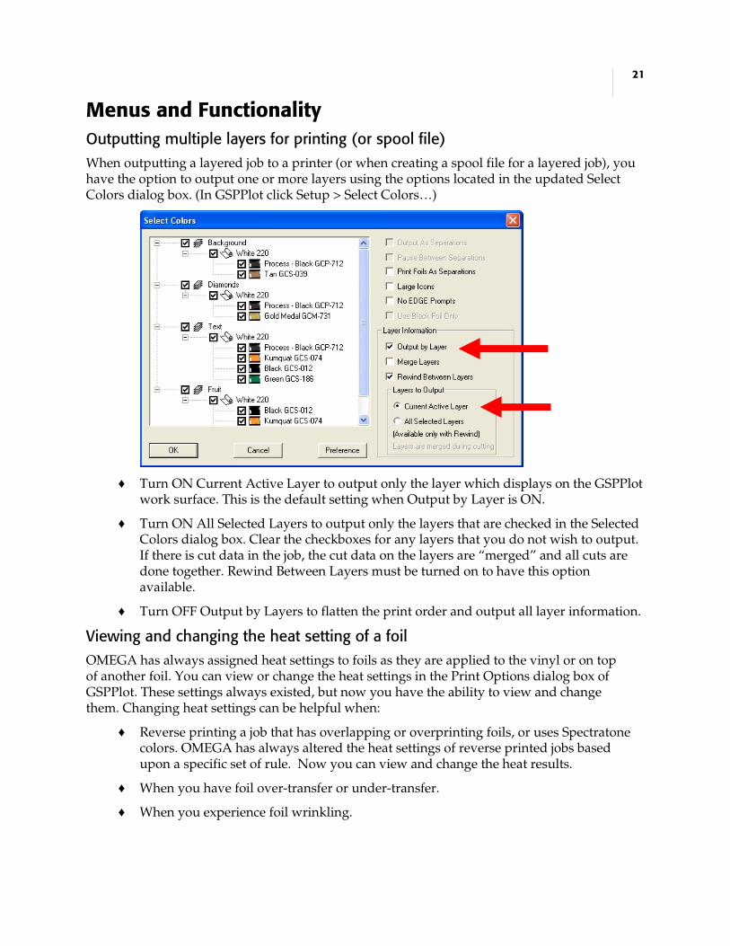
Menus and Functionality Outputting multiple layers for printing (or spool file) When outputting a layered job to a printer (or when creating a spool file for a layered job), you have the option to output one or more layers using the options located in the updated Select Colors dialog box. (In GSPPlot click Setup > Select Colors…)
♦ Turn ON Current Active Layer to output only the layer which displays on the GSPPlot work surface. This is the default setting when Output by Layer is ON.
♦ Turn ON All Selected Layers to output only the layers that are checked in the Selected Colors dialog box. Clear the checkboxes for any layers that you do not wish to output. If there is cut data in the job, the cut data on the layers are “merged” and all cuts are done together. Rewind Between Layers must be turned on to have this option available.
♦ Turn OFF Output by Layers to flatten the print order and output all layer information.
Viewing and changing the heat setting of a foil OMEGA has always assigned heat settings to foils as they are applied to the vinyl or on top of another foil. You can view or change the heat settings in the Print Options dialog box of GSPPlot. These settings always existed, but now you have the ability to view and change them. Changing heat settings can be helpful when:
♦ Reverse printing a job that has overlapping or overprinting foils, or uses Spectratone colors. OMEGA has always altered the heat settings of reverse printed jobs based upon a specific set of rule. Now you can view and change the heat results.
♦ When you have foil over-transfer or under-transfer.
♦ When you experience foil wrinkling.

22
To change a heat setting, right click a foil color and choose a heat setting from the Heat menu.
If you have multiple objects with the same foil color using different heat settings, (for example a black fill printing normally as well as black stroke that is assigned an overprint), you will have two heat settings such as Normal/Hot. The first heat setting applies to the first pass of the foil and the second applies to the second pass. When you have two heat settings you can change both of them by choosing a new double heat settings from the Heat menu.
Displaying a Heat column in the Foil Color list
The Foil Color list of the Print Options dialog box can display a Heat column which shows the heat setting applied when printing the foil. By default this column is hidden. To display the Heat column, right click a foil name and choose View to display the Options dialog box. Here you can determine which columns to display.
Tip: The heat setting of each foil color is indicated in the Heat column using an H for Hot
(overprint) and an N for Normal. If the Heat setting column is too narrow you may not see the double Heat indicator such as NH (Normal/Hot). Expand the column to view both indicators.

23
Other General Enhancements
♦ PLT files that contain images will have a smaller file size due to compressed thumbnails of images that display on-screen. (Compression of 24-bit thumbnails occurs automatically.)
♦ Improved export of spot gradient fills and rotated images when saving as an AI or EPS file.
♦ Improved export of GerberColor Spectratone gradient fills.
♦ Updated GerberColor Spectratone Palettes. The GerberColor Spectratone palette has been updated to include four new foil colors: Atomic Red, Light Navy, Vivid Blue, and Traffic Grey. In addition, several foils which have new formulations have been updated.
♦ Paper printing in Landscape mode is now centered on the paper.
♦ Help is now available from SplView by clicking Help > Help Topics or by pressing F1 when in the program.
♦ Vinyl-only legacy jobs with many shapes (20,000 or more) may take several minutes or more when opening in OMEGA 2.5 or higher. Save the file as a 2.5 or higher file to eliminate this problem when opening the file in the future. Use File Converter to import batches of older plot files and save them as OMEGA 2.5 plot files. If you do not want to overwrite existing files make sure Replace Existing Files is not checked, or save the files to a different directory. For detailed instructions, open File Converter and press F1 for help.
♦ Changed the behavior at the end of a cut job for some HP/GL plotters. On certain plotters, such as the Graphtec FC-7000 series, extra material would advance through the plotter after cutting completed. Sometimes the amount of material advanced was quite large. On other plotters, such as the Gerber FasTrack™ series, a “sheet-off” command was executed after cutting completed, even if the Automatic Cut-Off check box in the Start/End Position dialog was unchecked.
♦ Corrected problem with targets printing too far to the left when printing on a GERBER MAXX™ and cutting with an ODYSSEY XP™.
♦ Corrected several problems when printing OPOS targets for the GERBER P2C™ plotter using the GERBER MAXX.

24
P80398A - Copyright © 2006 Gerber Scientific International. OMEGA, GERBER P2C, GERBER MAXX, ODYSSEY XP, ImageRIP Pro and FasTrack are trademarks of Gerber Scientific Products. Adobe Illustrator is a registered trademarks of Adobe Systems, Inc. Belkin is a registered trademark of Belkin Corporation. Radio Shack is a registered trademark of Radio Shack Corporation. Windows is a registered trademark of Microsoft Corporation in the US and other countries. PANTONE® and other Pantone, Inc. trademarks are the property of Pantone, Inc. © Pantone, Inc., 2005.
♦ Most router RTP files created in OMEGA 2.5.1 are backward compatible with previous versions of ART Path (OMEGA 2.0 through 2.5). If there are shapes in the job which contain too many data points in the tool path, a message displays and the shapes are not included in the older format file.
♦ Note to existing Gerber ImageRIP customers: Gerber ImageRIP (not ImageRIP Pro or Plus by Onyx) does not support rotated or flipped images. (Gerber ImageRIP is no longer available for purchase.)
♦ If OMEGA and Photoshop are both running at the same time, Photoshop will automatically render the contents of the OMEGA clipboard into a raster format. If this occurs, the OMEGA file converter spontaneously starts to export the clipboard contents into a 24 bit raster format.
If the OMEGA clipboard content dimensions are physically large (50" x 50" or larger), this raster file export might exceed 1 GB, which may be beyond the limits of the system, causing Composer and other programs to become unresponsive.
Therefore, clipboard generation of images is now limited to 3000 pixels in the largest dimension. The clipboard generation limit does not affect copy and paste operations within Composer. Images larger than 3000 pixels can still be exported using the Composer file converter.


![[Maths] 2.5.1 matrices y determinantes mpf](https://img.pdfslide.us/doc/110x75/547d9777b4af9f6d5d8b4601/maths-251-matrices-y-determinantes-mpf.jpg)