Embed Size (px)
Citation preview
General changes and CAD-commands
Page 1
What’s new in IGEMS R9

General changes and CAD-commands
Page 2
What’s new in IGEMS R9
This document is not a complete manual.
It describes only the differences between IGEMS_R8 and IGEMS_R9
Table of contents
Chapter 1. General changes and CAD-commands ........................................... 3
Improved language support ......................................................................... 3
USB-dongle ................................................................................................ 3
Fillet ......................................................................................................... 3
Object snap Grip ........................................................................................ 3
Leader ...................................................................................................... 4
Improved AutoCAD DWG import .................................................................. 4
Paper space mode ................................................................................... 4
Chapter 2. Bonus 2010 ............................................................................... 5
Spur gear generator ................................................................................... 5
Chapter 3. Changes in the 2D-CAM module ................................................... 6
Fine Abrasive waterjet (FAW) ....................................................................... 6
Create Part ................................................................................................ 7
Automatic quantity .................................................................................. 7
Auto technology in Single and Auto commands .............................................. 7
Fence in Sheet prepare ............................................................................... 8
Parts in holes first ................................................................................ 9
Cutoff ....................................................................................................... 9
Cut of sheets ........................................................................................ 10
Cut of parts .......................................................................................... 11
Chapter 4. Bevel cut ................................................................................. 13
Loops on plasma cutting ........................................................................... 13
Bevel with different angles ..................................................................... 14
Standoff in Plasma cutting ......................................................................... 15
Loops on WaterJet cutting ......................................................................... 16
Advance Bevel ......................................................................................... 17
Zoom, Pan and Rotate ........................................................................ 17
Snap points ....................................................................................... 18
Delete connections ............................................................................. 18
Straight cuts in Advance Bevel ................................................................... 18
Multiple Advance Bevel Parts ..................................................................... 19
Chapter 5. Organizer ................................................................................ 21
General changes and CAD-commands
Page 3
Chapter 1.
General changes and CAD-commands
Improved language support
The language support in IGEMS R9 has been improved in order to allow extended languages.
USB-dongle
IGEMS R9 will be delivered with new USB-dongles. The new dongle will no longer require installation of any software drivers. IGEMS R9 will however still support the
old type of Safe Net dongle used in IGEMS R8 and older.
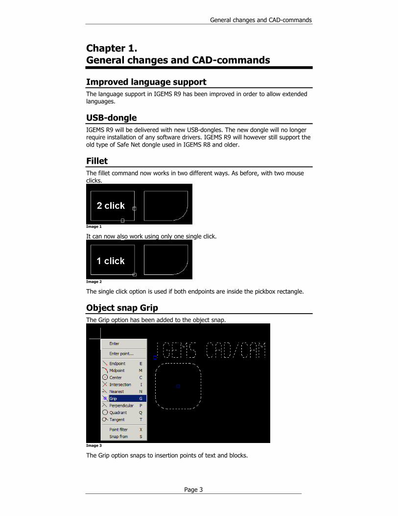
Fillet
The fillet command now works in two different ways. As before, with two mouse
clicks.
Image 1
It can now also work using only one single click.
Image 2
The single click option is used if both endpoints are inside the pickbox rectangle.
Object snap Grip
The Grip option has been added to the object snap.
Image 3
The Grip option snaps to insertion points of text and blocks.
General changes and CAD-commands
Page 4
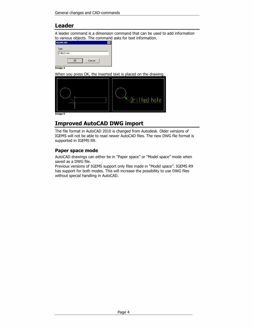
Leader
A leader command is a dimension command that can be used to add information to various objects. The command asks for text information.
Image 4
When you press OK, the inserted text is placed on the drawing.
Image 5
Improved AutoCAD DWG import
The file format in AutoCAD 2010 is changed from Autodesk. Older versions of
IGEMS will not be able to read newer AutoCAD files. The new DWG file format is supported in IGEMS R9.
Paper space mode
AutoCAD drawings can either be in “Paper space” or “Model space” mode when saved as a DWG file.
Previous versions of IGEMS support only files made in “Model space”. IGEMS R9 has support for both modes. This will increase the possibility to use DWG files
without special handling in AutoCAD.
Bonus 2010
Page 5
Chapter 2.
Bonus 2010
The Bonus package is always included when updating IGEMS from an older
version. It is also free when buying a new license when annual maintenance is included at the purchase. The bonus package in 2010 includes the same features
as the Bonus 2009 package but also a spur gear generator.
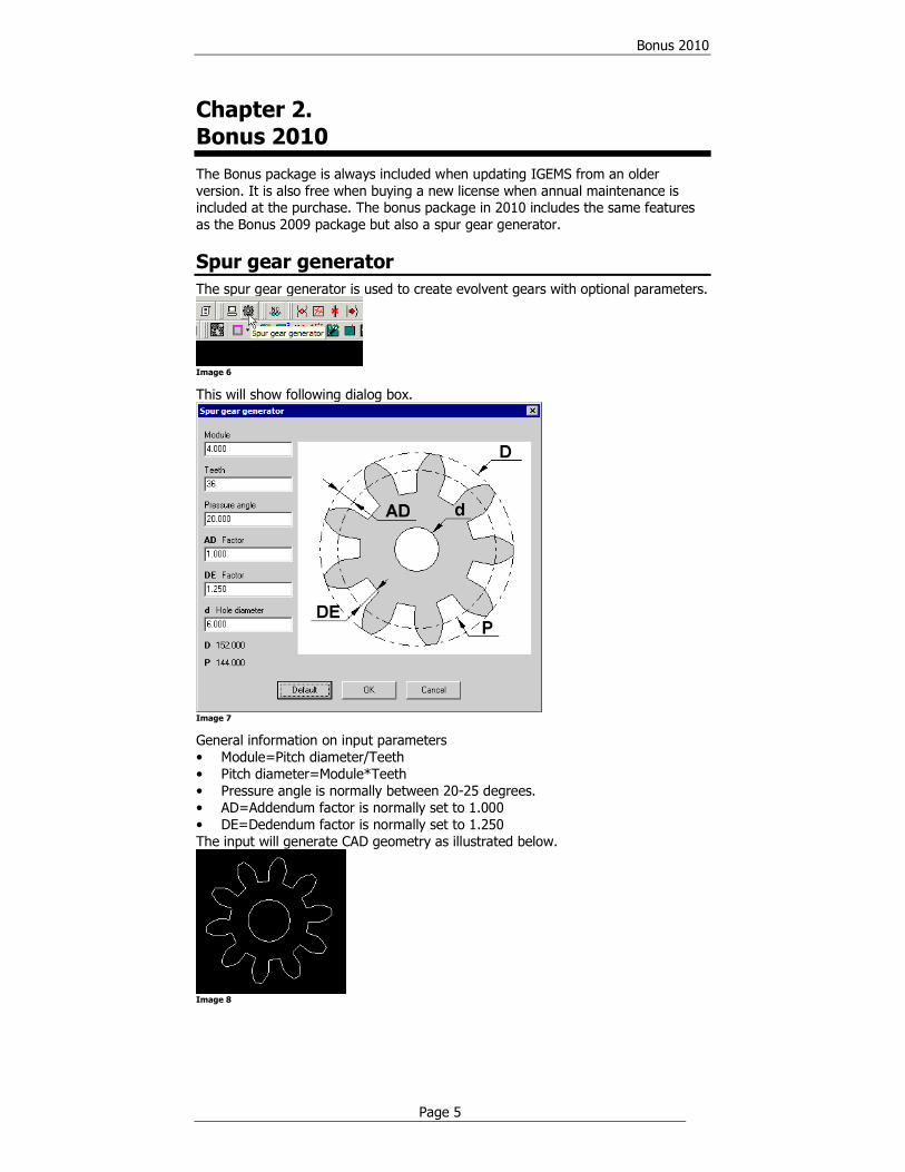
Spur gear generator
The spur gear generator is used to create evolvent gears with optional parameters.
Image 6
This will show following dialog box.
Image 7
General information on input parameters
• Module=Pitch diameter/Teeth
• Pitch diameter=Module*Teeth
• Pressure angle is normally between 20-25 degrees.
• AD=Addendum factor is normally set to 1.000
• DE=Dedendum factor is normally set to 1.250
The input will generate CAD geometry as illustrated below.
Image 8
Changes in the 2D-CAM module
Page 6
Chapter 3.
Changes in the 2D-CAM module
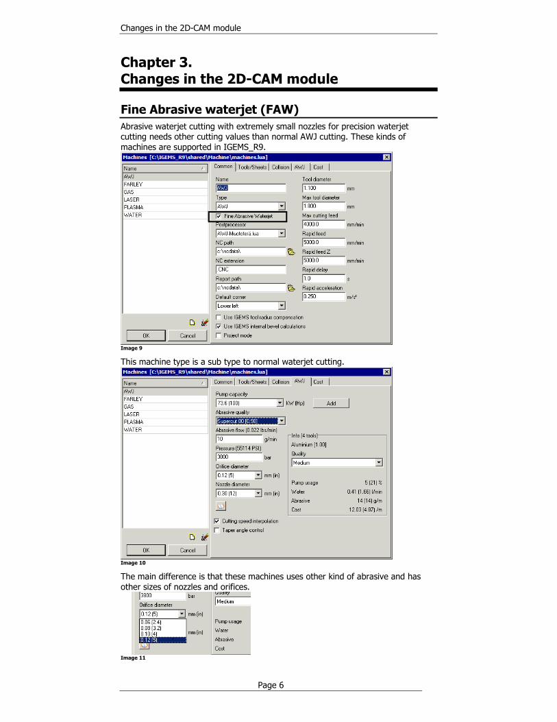
Fine Abrasive waterjet (FAW)
Abrasive waterjet cutting with extremely small nozzles for precision waterjet cutting needs other cutting values than normal AWJ cutting. These kinds of
machines are supported in IGEMS_R9.
Image 9
This machine type is a sub type to normal waterjet cutting.
Image 10
The main difference is that these machines uses other kind of abrasive and has
other sizes of nozzles and orifices.
Image 11
Changes in the 2D-CAM module
Page 7
The Orifice goes from 0.06 to 0.12 mm in diameter.
Image 12
The Nozzle diameter goes from 0.15 to 0.40 in diameter.
Create Part
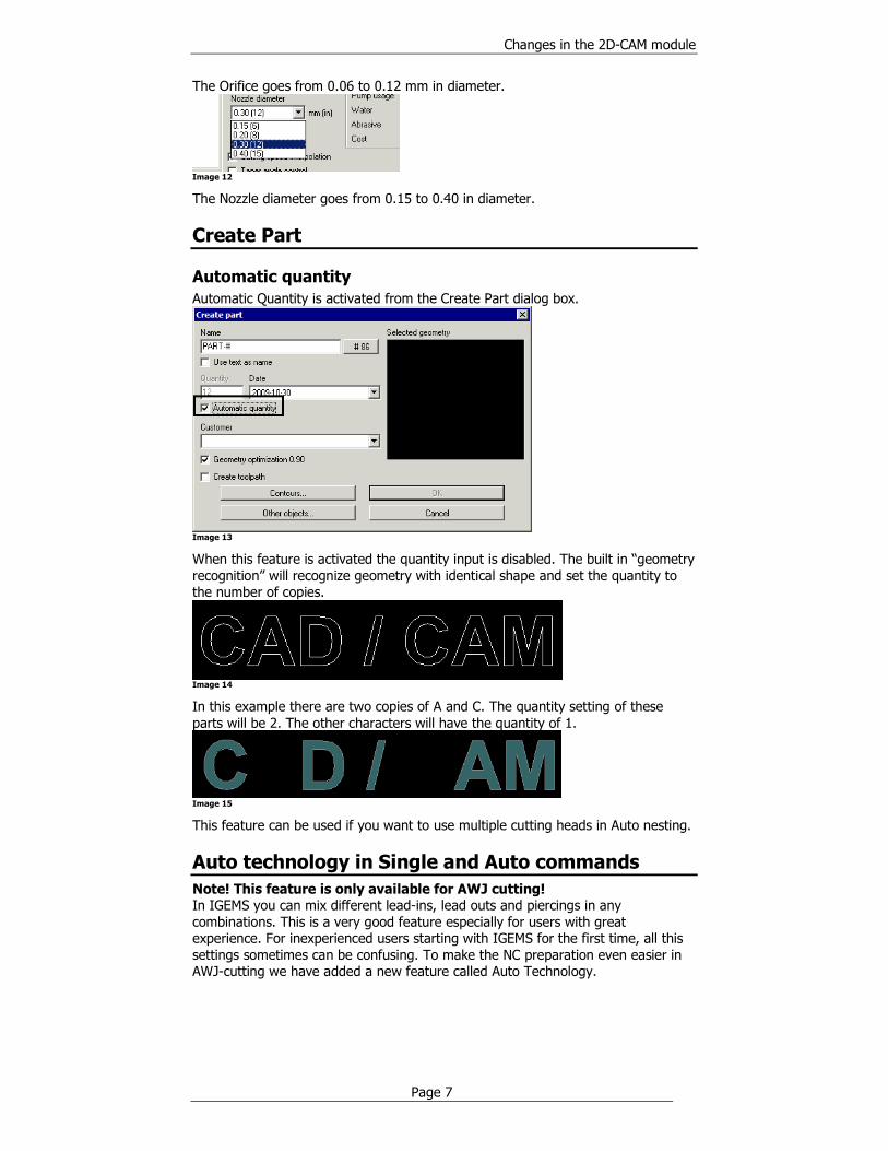
Automatic quantity
Automatic Quantity is activated from the Create Part dialog box.
Image 13
When this feature is activated the quantity input is disabled. The built in “geometry
recognition” will recognize geometry with identical shape and set the quantity to the number of copies.
Image 14
In this example there are two copies of A and C. The quantity setting of these
parts will be 2. The other characters will have the quantity of 1.
Image 15
This feature can be used if you want to use multiple cutting heads in Auto nesting.
Auto technology in Single and Auto commands
Note! This feature is only available for AWJ cutting! In IGEMS you can mix different lead-ins, lead outs and piercings in any
combinations. This is a very good feature especially for users with great experience. For inexperienced users starting with IGEMS for the first time, all this
settings sometimes can be confusing. To make the NC preparation even easier in AWJ-cutting we have added a new feature called Auto Technology.
Changes in the 2D-CAM module
Page 8
Image 16
You can switch between the User Technology and the Auto technology on the top of the dialog boxes for Auto and Single commands. The Auto technology can be
used in all cases except for materials that need special piercings. IGEMS intension
is to improve the functionality of the Auto technology in the future.
Image 17
The general idea is to work with Dynamic Linear Piercing (Released in IGEMS R8).
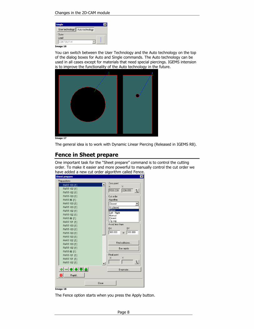
Fence in Sheet prepare
One important task for the “Sheet prepare” command is to control the cutting
order. To make it easier and more powerful to manually control the cut order we have added a new cut order algorithm called Fence.
Image 18
The Fence option starts when you press the Apply button.
Changes in the 2D-CAM module
Page 9
Image 19
The cutting order will be in that order the Fence is intersecting with the parts.
Image 20
IGEMS asks for the start point of the fence. (Point 1) Next Fence point (W=New start point, U=Increase radius, Y=Decrease radius) (Point 2)
1. The fence radius is pixel based, this means that you can control the fence radius relative to the parts by zooming in or out.
2. If you want to change the fence width, you can simply press U or Y. 3. The W will start a new fence.
Parts in holes first
Image 21
If the checkbox “Parts in holes” are activated then the cutting order are recalculated so that all parts located in holes are cut before the normal parts.
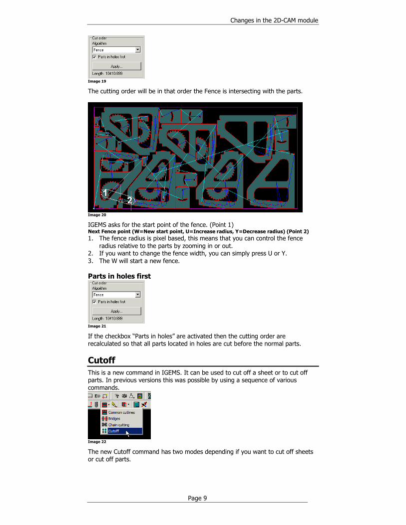
Cutoff
This is a new command in IGEMS. It can be used to cut off a sheet or to cut off parts. In previous versions this was possible by using a sequence of various
commands.
Image 22
The new Cutoff command has two modes depending if you want to cut off sheets or cut off parts.
Changes in the 2D-CAM module
Page 10
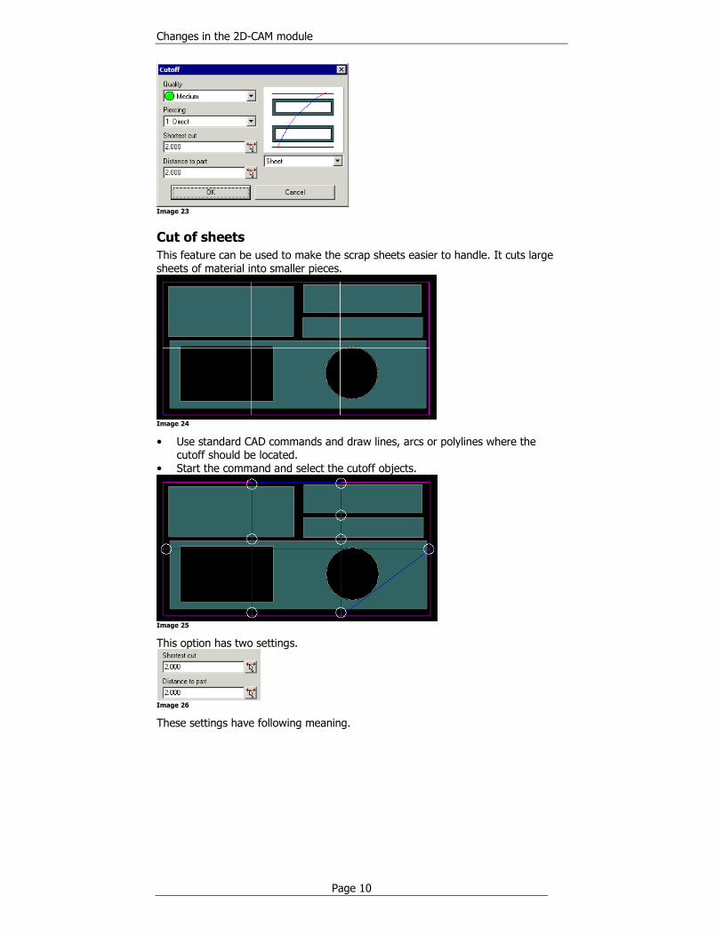
Image 23
Cut of sheets
This feature can be used to make the scrap sheets easier to handle. It cuts large sheets of material into smaller pieces.
Image 24
• Use standard CAD commands and draw lines, arcs or polylines where the cutoff should be located.
• Start the command and select the cutoff objects.
Image 25
This option has two settings.
Image 26
These settings have following meaning.
Changes in the 2D-CAM module
Page 11
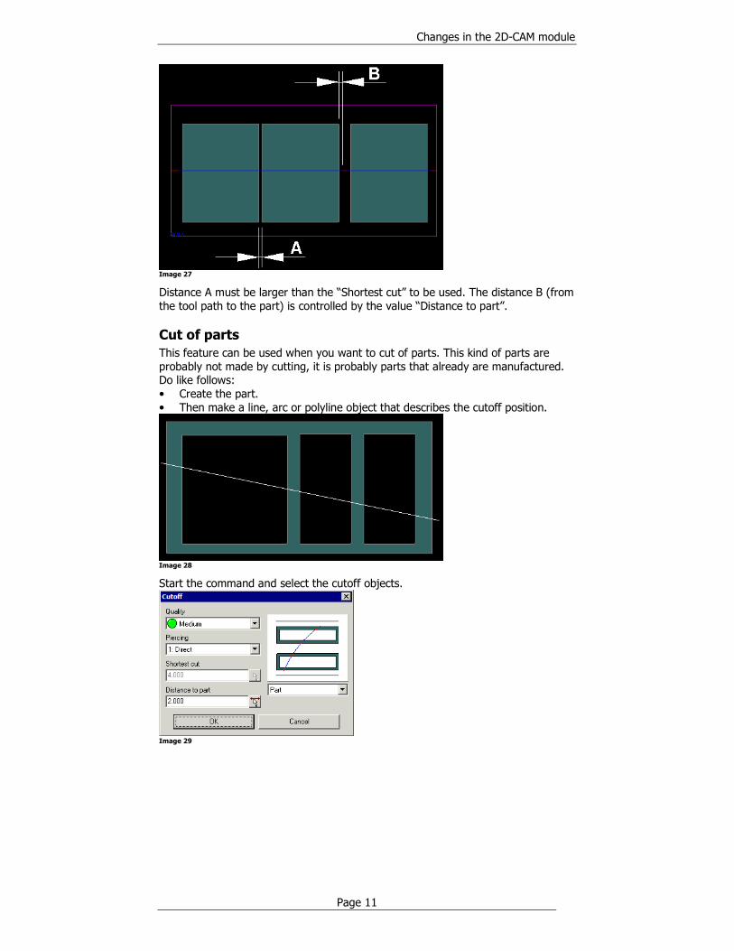
Image 27
Distance A must be larger than the “Shortest cut” to be used. The distance B (from
the tool path to the part) is controlled by the value “Distance to part”.
Cut of parts
This feature can be used when you want to cut of parts. This kind of parts are
probably not made by cutting, it is probably parts that already are manufactured. Do like follows:
• Create the part.
• Then make a line, arc or polyline object that describes the cutoff position.
Image 28
Start the command and select the cutoff objects.
Image 29
Changes in the 2D-CAM module
Page 12
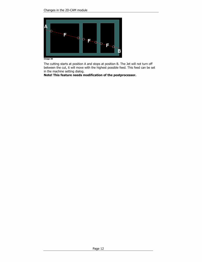
Image 30
The cutting starts at position A and stops at position B. The Jet will not turn off between the cut, it will move with the highest possible feed. This feed can be set
in the machine setting dialog. Note! This feature needs modification of the postprocessor.
Bevel cut
Page 13
Chapter 4.
Bevel cut
Features in the Bevel cut commands are improved. It now works in different ways
depending if machine type is set to waterjet or plasma. The feature has also got an Undo function.
Note: The new functionality needs changes in the postprocessor!
Loops on plasma cutting
Cutting technology that creates heat need outside loops to get a good result. In
previous versions of IGEMS the corner loops was added during the postprocessing. This could be a problem since the loop could damage other parts. IGEMS R9 now
supports loops when adding the tool path.
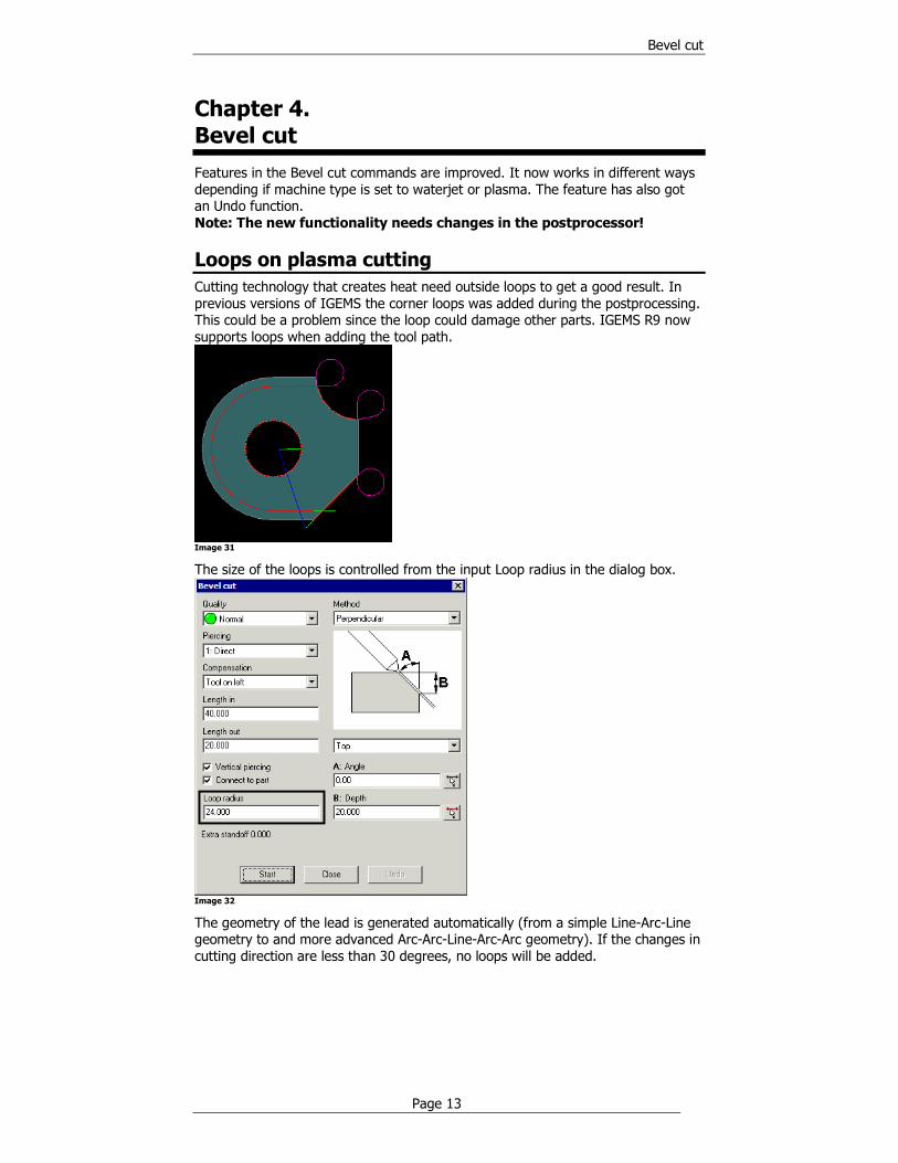
Image 31
The size of the loops is controlled from the input Loop radius in the dialog box.
Image 32
The geometry of the lead is generated automatically (from a simple Line-Arc-Line geometry to and more advanced Arc-Arc-Line-Arc-Arc geometry). If the changes in
cutting direction are less than 30 degrees, no loops will be added.
Bevel cut
Page 14
Image 33
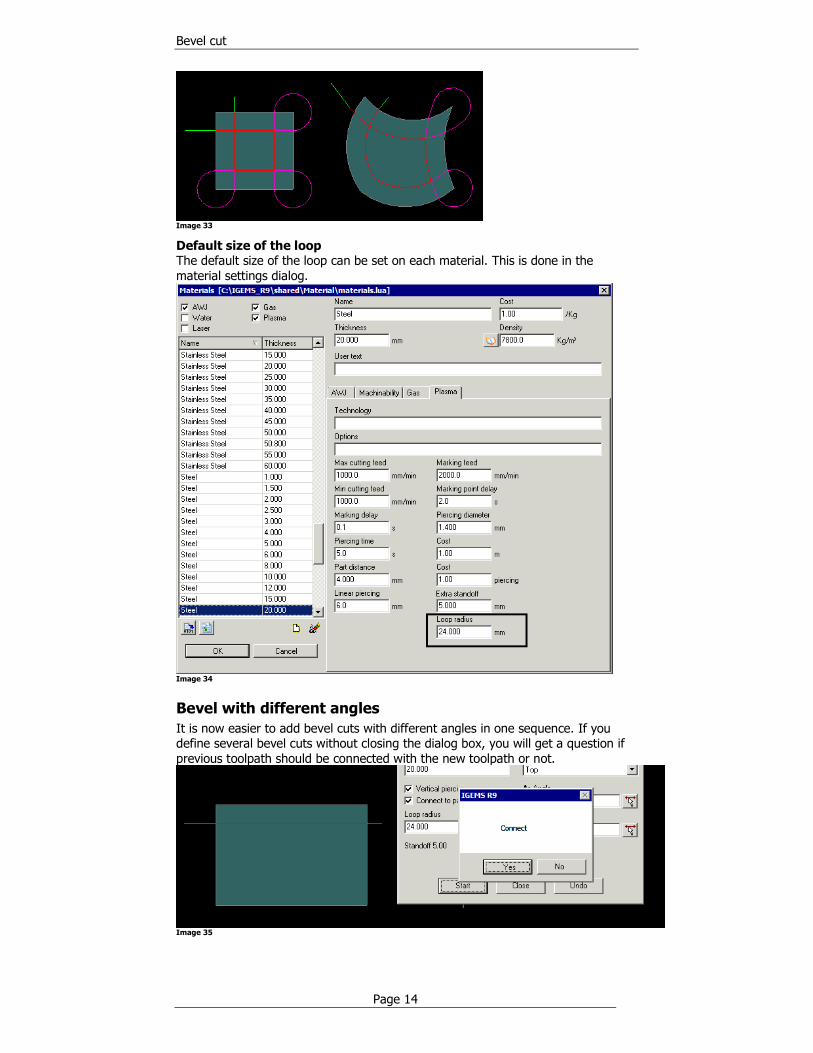
Default size of the loop The default size of the loop can be set on each material. This is done in the
material settings dialog.
Image 34
Bevel with different angles
It is now easier to add bevel cuts with different angles in one sequence. If you define several bevel cuts without closing the dialog box, you will get a question if
previous toolpath should be connected with the new toolpath or not.
Image 35
Bevel cut
Page 15
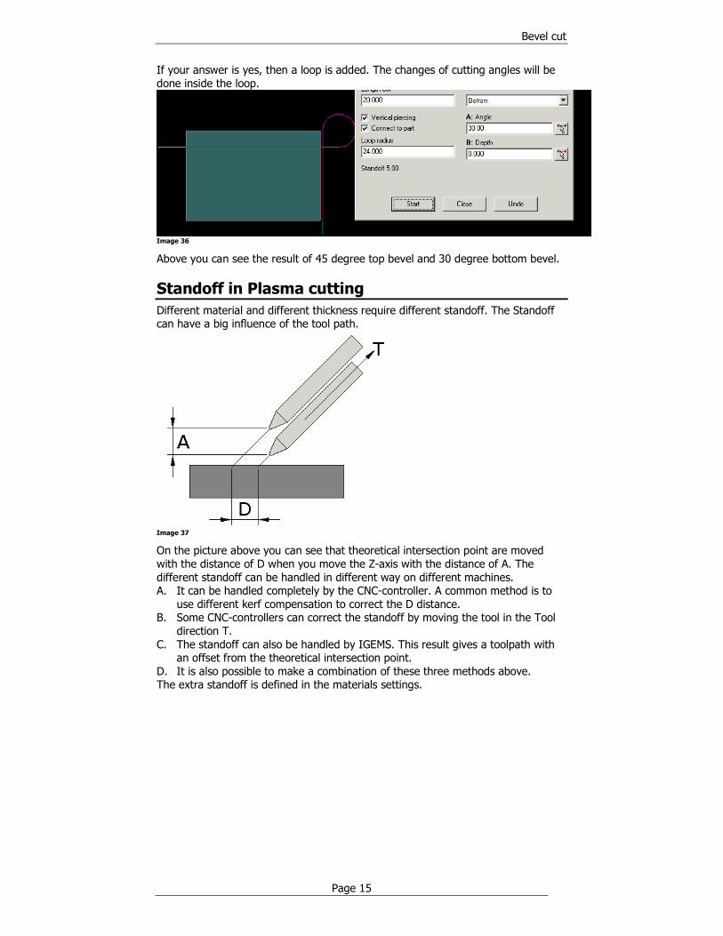
If your answer is yes, then a loop is added. The changes of cutting angles will be
done inside the loop.
Image 36
Above you can see the result of 45 degree top bevel and 30 degree bottom bevel.
Standoff in Plasma cutting
Different material and different thickness require different standoff. The Standoff can have a big influence of the tool path.
Image 37
On the picture above you can see that theoretical intersection point are moved
with the distance of D when you move the Z-axis with the distance of A. The
different standoff can be handled in different way on different machines. A. It can be handled completely by the CNC-controller. A common method is to
use different kerf compensation to correct the D distance. B. Some CNC-controllers can correct the standoff by moving the tool in the Tool
direction T.
C. The standoff can also be handled by IGEMS. This result gives a toolpath with an offset from the theoretical intersection point.
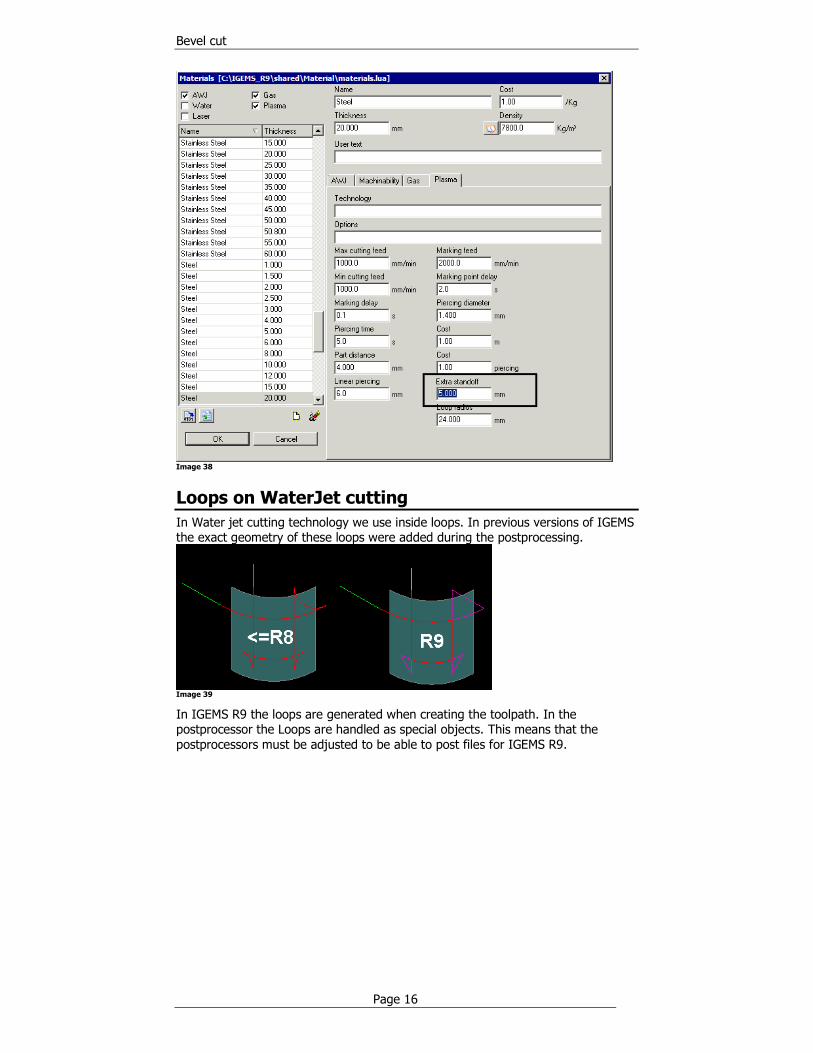
D. It is also possible to make a combination of these three methods above. The extra standoff is defined in the materials settings.
Bevel cut
Page 16
Image 38
Loops on WaterJet cutting
In Water jet cutting technology we use inside loops. In previous versions of IGEMS the exact geometry of these loops were added during the postprocessing.
Image 39
In IGEMS R9 the loops are generated when creating the toolpath. In the postprocessor the Loops are handled as special objects. This means that the
postprocessors must be adjusted to be able to post files for IGEMS R9.
Bevel cut
Page 17
Image 40
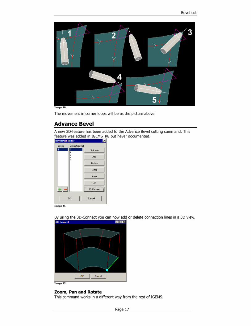
The movement in corner loops will be as the picture above.
Advance Bevel
A new 3D-feature has been added to the Advance Bevel cutting command. This
feature was added in IGEMS_R8 but never documented.
Image 41
By using the 3D-Connect you can now add or delete connection lines in a 3D view.
Image 42
Zoom, Pan and Rotate This command works in a different way from the rest of IGEMS.
Bevel cut
Page 18
Pan: Hold down the mouse wheel and move the mouse.
Zoom: By rotate the mouse wheel.
Rotate3D: By holding down the right button and move the mouse.
Snap points You can add connection lines from bottom to top or opposite. Snap points on all endpoints and midpoints.
You can also snap to closest point by select a snap point and then press Enter.
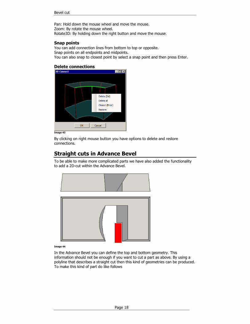
Delete connections
Image 43
By clicking on right mouse button you have options to delete and restore connections.
Straight cuts in Advance Bevel
To be able to make more complicated parts we have also added the functionality to add a 2D-cut within the Advance Bevel.
Image 44
In the Advance Bevel you can define the top and bottom geometry. This
information should not be enough if you want to cut a part as above. By using a polyline that describes a straight cut then this kind of geometries can be produced.
To make this kind of part do like follows
Bevel cut
Page 19
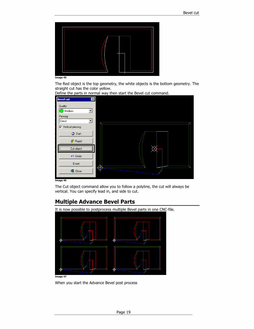
Image 45
The Red object is the top geometry, the white objects is the bottom geometry. The
straight cut has the color yellow. Define the parts in normal way then start the Bevel cut command.
Image 46
The Cut object command allow you to follow a polyline, the cut will always be
vertical. You can specify lead in, and side to cut.
Multiple Advance Bevel Parts
It is now possible to postprocess multiple Bevel parts in one CNC-file.
Image 47
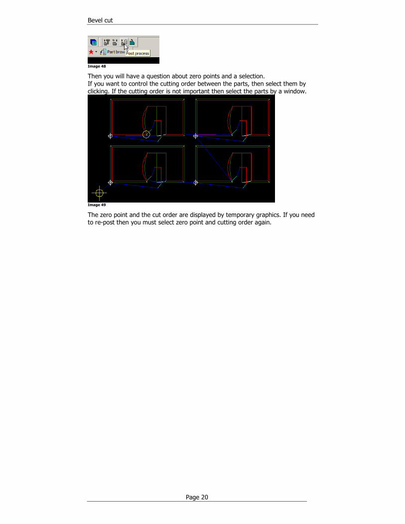
When you start the Advance Bevel post process
Bevel cut
Page 20
Image 48
Then you will have a question about zero points and a selection.
If you want to control the cutting order between the parts, then select them by
clicking. If the cutting order is not important then select the parts by a window.
Image 49
The zero point and the cut order are displayed by temporary graphics. If you need to re-post then you must select zero point and cutting order again.
Organizer
Page 21
Chapter 5.
Organizer
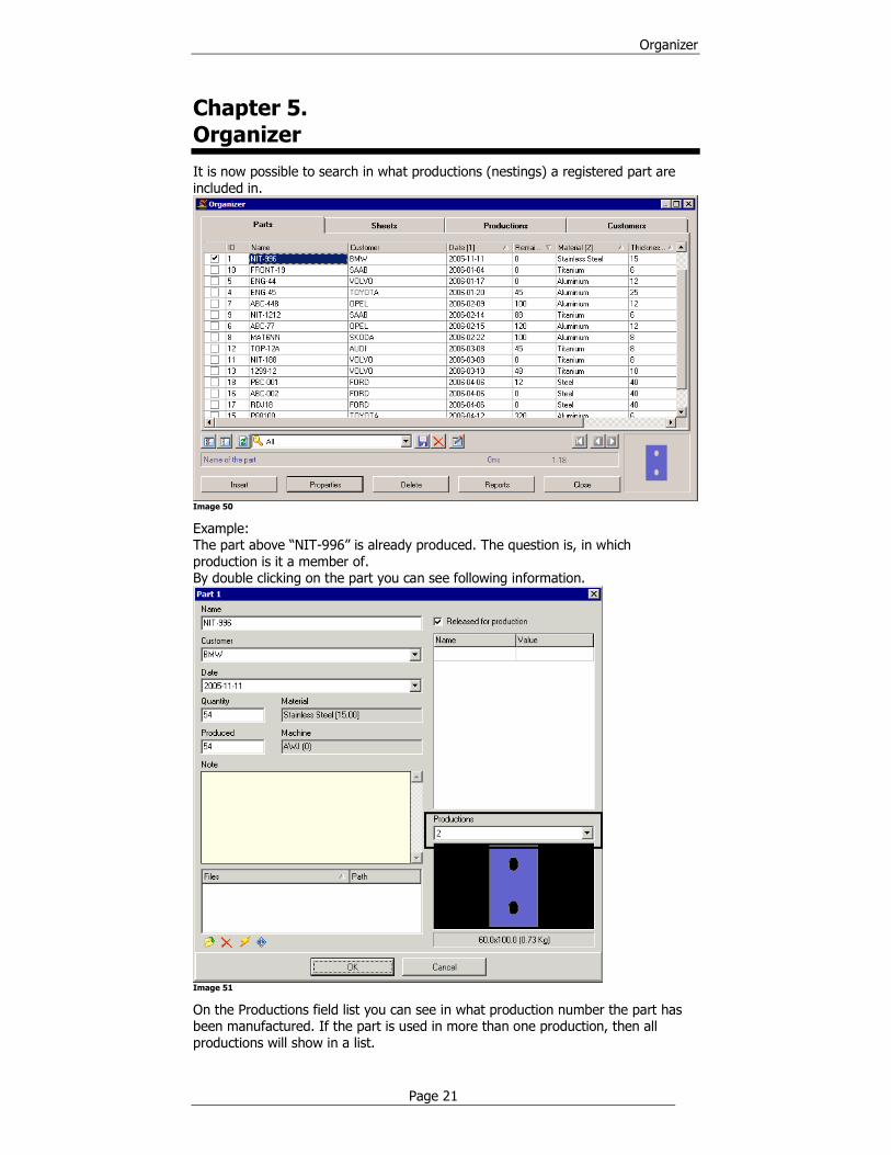
It is now possible to search in what productions (nestings) a registered part are
included in.
Image 50
Example: The part above “NIT-996” is already produced. The question is, in which
production is it a member of. By double clicking on the part you can see following information.
Image 51
On the Productions field list you can see in what production number the part has been manufactured. If the part is used in more than one production, then all
productions will show in a list.
Organizer
Page 22
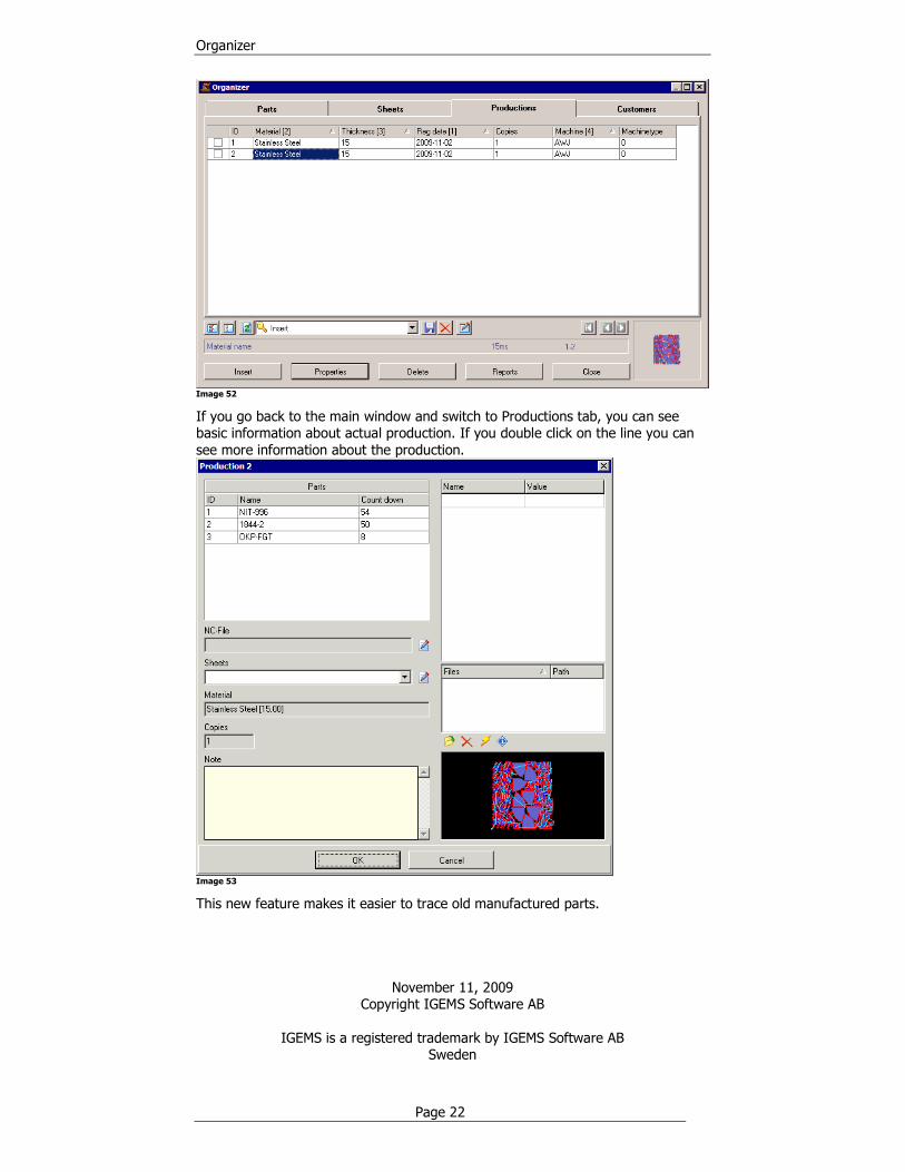
Image 52
If you go back to the main window and switch to Productions tab, you can see basic information about actual production. If you double click on the line you can
see more information about the production.
Image 53
This new feature makes it easier to trace old manufactured parts.
November 11, 2009 Copyright IGEMS Software AB
IGEMS is a registered trademark by IGEMS Software AB Sweden