Embed Size (px)
DESCRIPTION
This documents are about new updates in encounter tool of version 12
Citation preview

EDI System What's New 12.0
Product Version 12.0December 2012

© 2011-2012 Cadence Design Systems, Inc. All rights reserved.Printed in the United States of America.
Cadence Design Systems, Inc. (Cadence), 2655 Seely Ave., San Jose, CA 95134, USA.
Trademarks: Trademarks and service marks of Cadence Design Systems, Inc. (Cadence)contained in this document are attributed to Cadence with the appropriate symbol. For queriesregarding Cadence’s trademarks, contact the corporate legal department at the address shownabove or call 1-800-862-4522.
All other trademarks are the property of their respective holders.
Restricted Print Permission: This publication is protected by copyright and any unauthorizeduse of this publication may violate copyright, trademark, and other laws. Except as specified in thispermission statement, this publication may not be copied, reproduced, modified, published,uploaded, posted, transmitted, or distributed in any way, without prior written permission fromCadence. This statement grants you permission to print one (1) hard copy of this publicationsubject to the following conditions:
1. The publication may be used solely for personal, informational, and noncommercialpurposes;
2. The publication may not be modified in any way;3. Any copy of the publication or portion thereof must include all original copyright, trademark,
and other proprietary notices and this permission statement; and4. Cadence reserves the right to revoke this authorization at any time, and any such use shall
be discontinued immediately upon written notice from Cadence.
Disclaimer: Information in this publication is subject to change without notice and does notrepresent a commitment on the part of Cadence. The information contained herein is theproprietary and confidential information of Cadence or its licensors, and is supplied subject to, andmay be used only by Cadence’s customer in accordance with, a written agreement betweenCadence and its customer. Except as may be explicitly set forth in such agreement, Cadencedoes not make, and expressly disclaims, any representations or warranties as to thecompleteness, accuracy or usefulness of the information contained in this document. Cadencedoes not warrant that use of such information will not infringe any third party rights, nor doesCadence assume any liability for damages or costs of any kind that may result from use of suchinformation.
Restricted Rights: Use, duplication, or disclosure by the Government is subject to restrictions asset forth in FAR52.227-14 and DFAR252.227-7013 et seq. or its successor.
1111111111131313131521212324242528292929292930303030303031313131313333333333
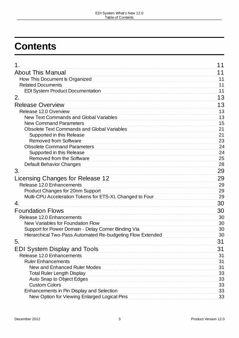
Contents
1.About This Manual
How This Document Is OrganizedRelated Documents
EDI System Product Documentation2.Release Overview
Release 12.0 OverviewNew Text Commands and Global VariablesNew Command ParametersObsolete Text Commands and Global Variables
Supported in this ReleaseRemoved from Software
Obsolete Command ParametersSupported in this ReleaseRemoved from the Software
Default Behavior Changes3.Licensing Changes for Release 12
Release 12.0 EnhancementsProduct Changes for 20nm SupportMulti-CPU Acceleration Tokens for ETS-XL Changed to Four
4.Foundation Flows
Release 12.0 EnhancementsNew Variables for Foundation FlowSupport for Power Domain - Delay Corner Binding ViaHierarchical Two-Pass Automated Re-budgeting Flow Extended
5.EDI System Display and Tools
Release 12.0 EnhancementsRuler Enhancements
New and Enhanced Ruler ModesTotal Ruler Length DisplayAuto Snap to Object EdgesCustom Colors
Enhancements in Pin Display and SelectionNew Option for Viewing Enlarged Logical Pins
December 2012 3 Product Version 12.0
EDI System What's New 12.0Table of Contents

3435353535363636363737373737393939394141414141414242434343434344
4646464647474848
505050
New Pin Shapes Option in Layer Control BarNew Option for Highlighting Pin Shapes on Net Selection
Enhancements in Flightline PreferencesNew Option for Displaying Only Clock NetsNew Options for Controlling Flightline Color and Width
Enhancement in the Ungroup FeatureLog File Enhancementfind_global Enhancementset_object_color EnhancementNew Command for Limiting Display of Return ValuesNew Command To Launch DB BrowserNew Form for Going to a Specific LocationNew DBTCL OptionNew Command to Control Message Severity Level
6.Multiple CPU Processing
Release 12.0 EnhancementsMemory Reporting Improved
7.Importing and Exporting the Design
Release 12.0 EnhancementslefOut and defOut Enhanced To Support Embedded BumpslefOut Enhanced To Output PG Bump Information along with PG Physical PinsNew Global Variable To Uniquify the DesignNew Global Variable for Power RoutingNew Options for Command add_shape
8.LEF-DEF Properties
Release 12.0 EnhancementsLEF 5.8 Properties for Creating New DRC Rules for 32-28 nm and Smaller Nodes
Cut Layer EnhancementsRouting Layer Enhancements
9.Wire Editing
Release 12.0 EnhancementsNew setSpecialRouteOption options for Supporting Multiple-Layer P/G PinsNew Option for Selecting/Deselecting Via along with WireNew setViaEdit Option for Creating Special ViasNew setViaEdit Option To Prevent Replacement of Existing Via with New, Overlapping ViaNew setEdit Option for Stretching Wires Along with Via
10.Flip Chip
Release 12.0 Enhancements
December 2012 4 Product Version 12.0
EDI System What's New 12.0Table of Contents

5050515152535354545555555556565657595959595960626263636465656565666667676767676868696969
Flip Chip Flightline EnhancementsHighlight by SelectionColored FlightlinesObject-Specific FlightlinesDIFFPAIR-Based HighlightingNew Display Flightline Form
Add Bump to Array Form Renamed and EnhancedNew changeBumpMaster ParametersNew Change Bump Master FormEnhanced Assign/Unassign Signals Form
New Auto Zoom FeatureNew Filter OptionsNew Criterion for Assigning Bumps
Support for Assigning Multiple PG Pads to Multi BumpsNew assignPGBumps ParameterNew Option for Flip Chip Routing in View AreaObsolete fcroute Parameters
11.Partitioning
Release 12.0 EnhancementsSupport for Promoting Macro PinsNew Parameters for Specifying OffsetPin Editor Capability EnhancedSpecify Partition GUI Form UpdatedalignPtnClone Command EnhancedcheckPinAssignment Command EnhancedNew Parameter to Specify Keep Out SpacingPin Constraint Commands ConsolidatedMulti-threading Support for savePartition CommandSupport for Saving and Loading Selective Floorplan Data
New Parameter Added to the savePartition CommandNew Parameter Added to the assembleDesign CommandNew set_ptn_fplan_mode Command AddedNew get_ptn_fplan_mode Command Added
12.Floorplanning
Release 12.0 EnhancementscreatePGPin Command EnhancedcreateObsAroundInst Command is now Obsoleteadd_ndr Command EnhancedSupport for Reporting Narrow ChannelsSupport for Handling Master/Clones in Different HierarchyEnhanced Power Domain Placement CapabilityEnhanced Auto-shaping for Placing Modules
December 2012 5 Product Version 12.0
EDI System What's New 12.0Table of Contents

6970717173737373737375757575757576767676767778787878797979798082828282828384
848485
Support for Virtual fence Option to Handle User-specified SeedsNew Command to Generate Partition Fences Around FlexmodelsSupport for Bus Guides in Relative FloorplanBlackblob Capability made Obsolete
13.Structured Data Path
Release 12.0 EnhancementsreadSdpFile Command Enhanced To Support More Than 10 skipSpace VariablesSupport Added for Reusing SDP InstantiationsNew Buttons in the SDP Browser
14.Multiple Supply Voltage (MSV)
Release 12.0 EnhancementsNew Options for optPowerSwitchNew Options for reportPowerDomainNew Option for replacePowerSwitch
15.NanoRoute Router
Release 12.0 EnhancementsNanoRoute Support for LEF Properties EnhancedgetNanoRouteMode and setNanoRouteMode Commands ModifiedEnhanced Violation Marker Support
16.TrialRoute Router
Release 12.0 EnhancementsTrialRoute Support for get_metric APIs
17.Timing Budgeting
Release 12.0 EnhancementsPower Pin Support in Budgeted Timing Models for Low Power DesignsJustify Budget Enhanced
18.RC Extraction
Release 12.0 EnhancementsRCDB Reading Enhanced to Fix ErrorsNew Command for Providing Information about the Contents of the RCDBObsolete Command Parameters - Removed from the SoftwareTQRC/IQRC Enhanced to Complete Broken RC NetworksTQRC/IQRC Enhanced to Perform Incremental Extraction After defIn and Metal FillCommandsAccuracy of PreRoute Extraction Enhanced for Signal NetsReduction in Peak Memory Consumption by spefIn in Sequential Mode
December 2012 6 Product Version 12.0
EDI System What's New 12.0Table of Contents

86868686868686878888888989898989909090919191919192929293939393939393939394959597979797
19.Timing
Release 12.0 EnhancementsConstraint Handling Enhancements
Ability to Override Local Clock Latency ValueReporting Enhancements
Added New Global Variable to Track Reported Paths LimitAbility to Report on AOCV Stage CountsTiming Report Enhanced to Show Markers for PinsAdded New Command to Report AOCV Derating FactorsAdded New Parameters for Statistical DeratingAbility to Perform Arc-Based AOCV Weight AnalysisAdded New Global to Improve Reporting of Clock ObjectsAdded New Property AttributeAdded New Property to Report ConstantsAdded New Library PropertiesReport_timing Command Enhanced
Timing ModelingAbility to Perform AOCV-Based ETM Extractiondo_extract_model Command Enhancements
Other EnhancementsAbility to Perform AOCV Analysis on Data PathsAdded New Property to Report MacrosAdded New Global to Control Clock Reconvergence
20.Timing Debug
New Options for load_timing_debug_report21.Verification
Release 12.0 EnhancementsNew Command To Support 20nm and Lower DRC RulesVerify Geometry Enhancements
Option -minPinArea Now ObsoleteOption -warning Now Obsolete
Violation Browser EnhancementsAuto Zoom Enhanced To Display Only Active Layers for ViolationsOption Added for Limiting Number of Errors Displayed Per TypeSupport Added for Complex Logical Expressions for Filtering ViolationsNew Forms Added for Loading and Saving DRC Markers
22.Power Calculation
Release 12.0 Enhancementsread_activity_file Parameters Consolidated
December 2012 7 Product Version 12.0
EDI System What's New 12.0Table of Contents
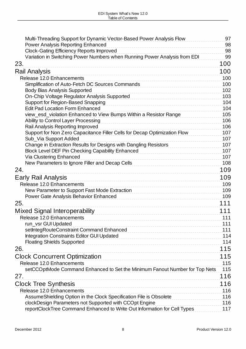
97989899
100100
100100102103104104105106106107107107107107108
109109109109109
111111
111111111114114
115115115115
116116116116116117
Multi-Threading Support for Dynamic Vector-Based Power Analysis FlowPower Analysis Reporting EnhancedClock-Gating Efficiency Reports ImprovedVariation in Switching Power Numbers when Running Power Analysis from EDI
23.Rail Analysis
Release 12.0 EnhancementsSimplification of Auto-Fetch DC Sources CommandsBody Bias Analysis SupportedOn-Chip Voltage Regulator Analysis SupportedSupport for Region-Based SnappingEdit Pad Location Form Enhancedview_esd_violation Enhanced to View Bumps Within a Resistor RangeAbility to Control Layer ProcessingRail Analysis Reporting ImprovedSupport for Non Zero Capacitance Filler Cells for Decap Optimization FlowSub_Via Support AddedChange in Extraction Results for Designs with Dangling ResistorsBlock Level DEF Pin Checking Capability EnhancedVia Clustering EnhancedNew Parameters to Ignore Filler and Decap Cells
24.Early Rail Analysis
Release 12.0 EnhancementsNew Parameter to Support Fast Mode ExtractionPower Gate Analysis Behavior Enhanced
25.Mixed Signal Interoperability
Release 12.0 Enhancementsrun_vsr GUI UpdatedsetIntegRouteConstraint Command EnhancedIntegration Constraints Editor GUI UpdatedFloating Shields Supported
26.Clock Concurrent Optimization
Release 12.0 EnhancementssetCCOptMode Command Enhanced to Set the Minimum Fanout Number for Top Nets
27.Clock Tree Synthesis
Release 12.0 EnhancementsAssumeShielding Option in the Clock Specification File is ObsoleteclockDesign Parameters not Supported with CCOpt EnginereportClockTree Command Enhanced to Write Out Information for Cell Types
December 2012 8 Product Version 12.0
EDI System What's New 12.0Table of Contents

118118118118118
119119119119119
120120120120120120120120121121
122122122122122122
124124124124
125125125125
126126126126
127127127
28.OpenAccess
Release 12.0 EnhancementsNew Command to Access the 5.x Library StructureNew Parameter to Add Voltage Information to the Nets
29.TSV
Release 12.0 EnhancementsEmbedded Bump Flow Supported in Hierarchical DesignsNew Parameter Added to Output Selected Bumps
30.Timing Optimization
Release 12.0 EnhancementsNew Command IntroducedtimeDesign Command UpdatedreclaimArea Command UpdatedsetOptMode Command Updated
New Parameters AddedGigaOpt as the Default Optimization Engine
Obsolete Parameters31.Placement
Release 12 EnhancementsNew CommandsNew Options for setPlaceModeNew Option for addFillerGap
32.Yield Analysis
Release 12.0 EnhancementsYield Analysis Discontinued
33.Delay Calculation
Release 12.0 EnhancementsVectorized Delay Calculation Support in MMMC with AAE
34.Netlist-to-Netlist
Release 12.0 EnhancementsrunN2NOpt -optimizeYield Parameter Now Obsolete
35.Prototyping Foundation Flow
Release 12.0 Enhancements
December 2012 9 Product Version 12.0
EDI System What's New 12.0Table of Contents

127127127128128
129129129
New Command to Control Initial FloorplanNew Command to Generate Floorplan for Prototypingset_proto_mode Command Updatedset_proto_model Command Updatedload_timing_debug_report Command Updated
36.Signal Integrity Analysis
setSIMode Command Enhanced
December 2012 10 Product Version 12.0
EDI System What's New 12.0Table of Contents
1
About This ManualThis manual provides information about Product Version 12 of the Cadence® Encounter® DigitalImplementation System family of products.
The Encounter Digital Implementation System (EDI System) family encompasses the followingproducts:
Encounter Digital Implementation System LEncounter Digital Implementation System XLNanoRoute® Ultra SoC Routing SolutionVirtuoso® Digital ImplementationEncounter Timing System LEncounter Timing System XLEncounter Power System LEncounter Power System XLFirst Encounter™ LFirst Encounter XLFirst Encounter GXL
How This Document Is OrganizedThis What's New manual is organized into chapters that cover broad areas of EDI Systemsoftware functionality. Each chapter contains topics that may address one or more of the followingareas:
New functionality in the EDI System software and enhancements made to existing formsand commands to support a new feature.Changes in default behavior, name changes to existing commands and forms, and syntaxchanges.Features that were removed since version 10 of the software.Major documentation changes, such as a new chapter or substantial reorganization.
Related DocumentsFor more information about the EDI System family of products, see the following documents. Youcan access these and other Cadence documents with the Cadence Help documentation system.
EDI System Product Documentation
December 2012 11 Product Version 12.0
EDI System What's New 12.0About This Manual
EDI System Known Problems and SolutionsDescribes important Cadence Change Requests (CCRs) for the EDI System family ofproducts, including solutions for working around known problems.
EDI System User GuideDescribes how to install and configure the EDI System software, and provides strategies forimplementing digital integrated circuits.
EDI System Text Command ReferenceDescribes the EDI System text commands, including syntax and examples.
EDI System Menu ReferenceProvides information specific to the forms and commands available from the EDI Systemgraphical user interface.
EDI System Database Access Command ReferenceLists all of the EDI System database access commands and provides a brief description ofsyntax and usage.
EDI System Foundation Flows User GuideDescribes how to use the scripts that represent the recommended implementation flows fordigital timing closure with the EDI System software.
EDI System Library Development GuideDescribes library development guidelines for the independent tools that make up the EDISystem family of products.
Mixed Signal Interoperability GuideDescribes the digital mixed-signal flow.
README fileContains installation, compatibility, and other prerequisite information, including a list ofCadence Change Requests (CCRs) that were resolved in this release. You can read thisfile online at downloads.cadence.com.
December 2012 12 Product Version 12.0
EDI System What's New 12.0About This Manual

2
Release OverviewRelease 12.0 Overview
New Text Commands and Global VariablesNew Command ParametersObsolete Text Commands and Global Variables
Supported in this ReleaseRemoved from Software
Obsolete Command ParametersSupported in this ReleaseRemoved from the Software
Default Behavior Changes
Release 12.0 Overview
New Text Commands and Global Variables
The following table lists the commands that were added to the EDI System software. The secondcolumn identifies the chapter of the EDI System Text Command Reference where the commandis documented.
New Commands and Globals Chapter
create_power_pads Rail AnalysisCommands
create_route_type BasicDatabaseAccess TclCommands
db_browser GUICommands
dd_get OpenAccessCommands
delete_route_type BasicDatabaseAccess TclCommands
generate_fence FloorplanCommandsand GlobalVariables
get_ptn_fplan_mode PartitionCommandsand Global
December 2012 13 Product Version 12.0
EDI System What's New 12.0Release Overview

Variables
get_well_tap_mode PlacementCommandsand GlobalVariables
getPinConstraint PartitionCommandsand GlobalVariables
init_design_uniquify Import andExportCommandsand GlobalVariables
place_connnected PlacementCommandsand GlobalVariables
proto_design PrototypingFoundationFlowCommands
report_pba_aocv_derate TimingAnalysisCommands
report_rcdb RCExtractionCommands
set_message GeneralCommandsand GlobalVariables
set_voltage_regulator_module Rail AnalysisCommands
set_well_tap_mode PlacementCommandsand GlobalVariables
set_ptn_fplan_mode PartitionCommandsand GlobalVariables
set_proto_design_mode PrototypingFoundationFlowCommands
December 2012 14 Product Version 12.0
EDI System What's New 12.0Release Overview

timing_cppr_skip_clock_reconvergence TimingGlobalVariables
timing_extract_model_aocv_mode TimingGlobalVariables
timing_property_clock_used_as_data_unconstrained_clock_source_paths TimingGlobalVariables
timing_report_enable_markers TimingGlobalVariables
timing_report_enable_max_path_limit_crossed TimingGlobalVariables
verify_drc VerifyCommands
New Command Parameters
The following table lists the parameters that were added to the EDI System software. The secondcolumn identifies the chapter of the EDI System Text Command Reference where the commandis documented.
New Parameters Chapter
add_ndr -hard_spacing -name
Floorplan Commands and GlobalVariables
add_shape-shape -shield_net -status -user_class
Import and Export Commands andGlobal Variables
addFillerGap-radius
Placement Commands and GlobalVariables
alignPtnClone-layer-track
Partition Commands and GlobalVariables
analyze_early_rail-turbo-off_rails
Rail Analysis Commands
assembleDesign-fplan
Partition Commands and GlobalVariables
December 2012 15 Product Version 12.0
EDI System What's New 12.0Release Overview

assignBump-ratio
Flip Chip Commands and GlobalVariables
assignIoPins-promoteMacroPin
Partition Commands and GlobalVariables
assignPGBumps-checkerboard
Flip Chip Commands and GlobalVariables
assignPtnPin-promoteMacroPin
Partition Commands and GlobalVariables
autoGenRelativeFPlan-busGuide
Floorplan Commands and GlobalVariables
changeBumpMaster-bump_name-selected
Flip Chip Commands and GlobalVariables
checkFPlan -narrow_channel
Floorplan Commands and GlobalVariables
checkPinAssignment-ignore-report_violating_pin
Partition Commands and GlobalVariables
createNetGroup -keep_out_spacing
Partition Commands and GlobalVariables
createPGPin -length -onDie -selected -width
Floorplan Commands and GlobalVariables
createPinBlkg -offset_end -offset_start
Partition Commands and GlobalVariables
createPinGroup -keep_out_spacing
Partition Commands and GlobalVariables
createPinGuide -offset_end -offset_start
Partition Commands and GlobalVariables
dbShape-maxPoint
Basic Database Access TclCommands
do_extract_model-pg
Timing Modeling Commands
editPin-include_rectilinear_edge-layer_priority-pattern-reverse_alternate
Partition Command and GlobalVariables
editSelect Wire Edit Commands
December 2012 16 Product Version 12.0
EDI System What's New 12.0Release Overview
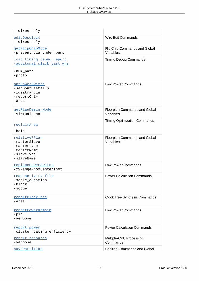
-wires_only
editDeselect -wires_only
Wire Edit Commands
getFlipChipMode-prevent_via_under_bump
Flip Chip Commands and GlobalVariables
load_timing_debug_report-additonal_slack_past_wns
-num_path-proto
Timing Debug Commands
optPowerSwitch-setDontUseCells-idsatmargin-reportOnly-area
Low Power Commands
getPlanDesignMode-virtualFence
Floorplan Commands and GlobalVariables
reclaimArea
-hold
Timing Optimization Commands
relativeFPlan-masterSlave-masterType-masterName-slaveType-slaveName
Floorplan Commands and GlobalVariables
replacePowerSwitch-xyRangeFromCenterInst
Low Power Commands
read_activity_file-scale_duration-block-scope
Power Calculation Commands
reportClockTree-area
Clock Tree Synthesis Commands
reportPowerDomain-pin-verbose
Low Power Commands
report_power–cluster_gating_efficiency
Power Calculation Commands
report_resource-verbose
Multiple-CPU ProcessingCommands
savePartition Partition Commands and Global
December 2012 17 Product Version 12.0
EDI System What's New 12.0Release Overview

-fplan Variables
set_clock_latency -clock_gate
Timing Constraint Commands
setDelayCalMode-combine_mmmc
Delay Calculation Commands
setEdit-stretch_with_intersect
Wire Edit Commands
setFlipChipMode-prevent_via_under_bump
Flip Chip Commands and GlobalVariables
setOaxMode-saveNetVoltage
OpenAccess Commands
setOptMode
-timeDesignNumPaths
-timeDesignExpandedView
-timeDesignReportNet
-postRouteAreaReclaim
Timing Optimization Commands
setPinConstraint-area-corner-corner_to_pin_distance-depth-global-side-target_layers-use_min_width_as_depth-width
Partition Commands and GlobalVariables
setPlaceMode-fillerGapRadius -prerouteAsObs-congRepairEffort
Placement Commands and GlobalVariables
December 2012 18 Product Version 12.0
EDI System What's New 12.0Release Overview
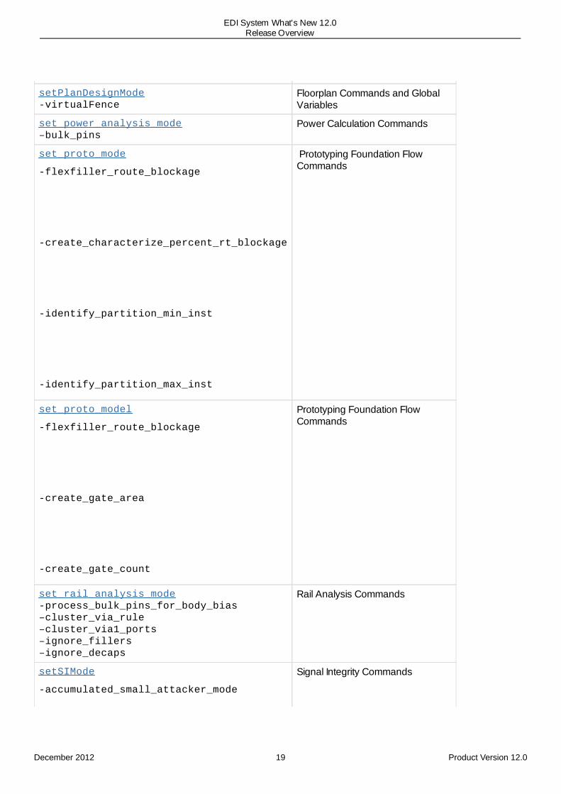
setPlanDesignMode-virtualFence
Floorplan Commands and GlobalVariables
set_power_analysis_mode–bulk_pins
Power Calculation Commands
set_proto_mode
-flexfiller_route_blockage
-create_characterize_percent_rt_blockage
-identify_partition_min_inst
-identify_partition_max_inst
Prototyping Foundation FlowCommands
set_proto_model
-flexfiller_route_blockage
-create_gate_area
-create_gate_count
Prototyping Foundation FlowCommands
set_rail_analysis_mode-process_bulk_pins_for_body_bias–cluster_via_rule–cluster_via1_ports–ignore_fillers–ignore_decaps
Rail Analysis Commands
setSIMode
-accumulated_small_attacker_mode
Signal Integrity Commands
December 2012 19 Product Version 12.0
EDI System What's New 12.0Release Overview
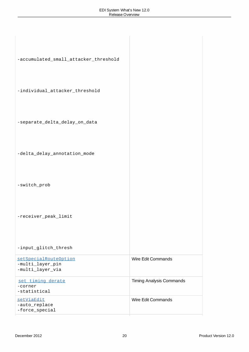
-accumulated_small_attacker_threshold
-individual_attacker_threshold
-separate_delta_delay_on_data
-delta_delay_annotation_mode
-switch_prob
-receiver_peak_limit
-input_glitch_thresh
setSpecialRouteOption-multi_layer_pin-multi_layer_via
Wire Edit Commands
set_timing_derate-corner-statistical
Timing Analysis Commands
setViaEdit-auto_replace-force_special
Wire Edit Commands
December 2012 20 Product Version 12.0
EDI System What's New 12.0Release Overview
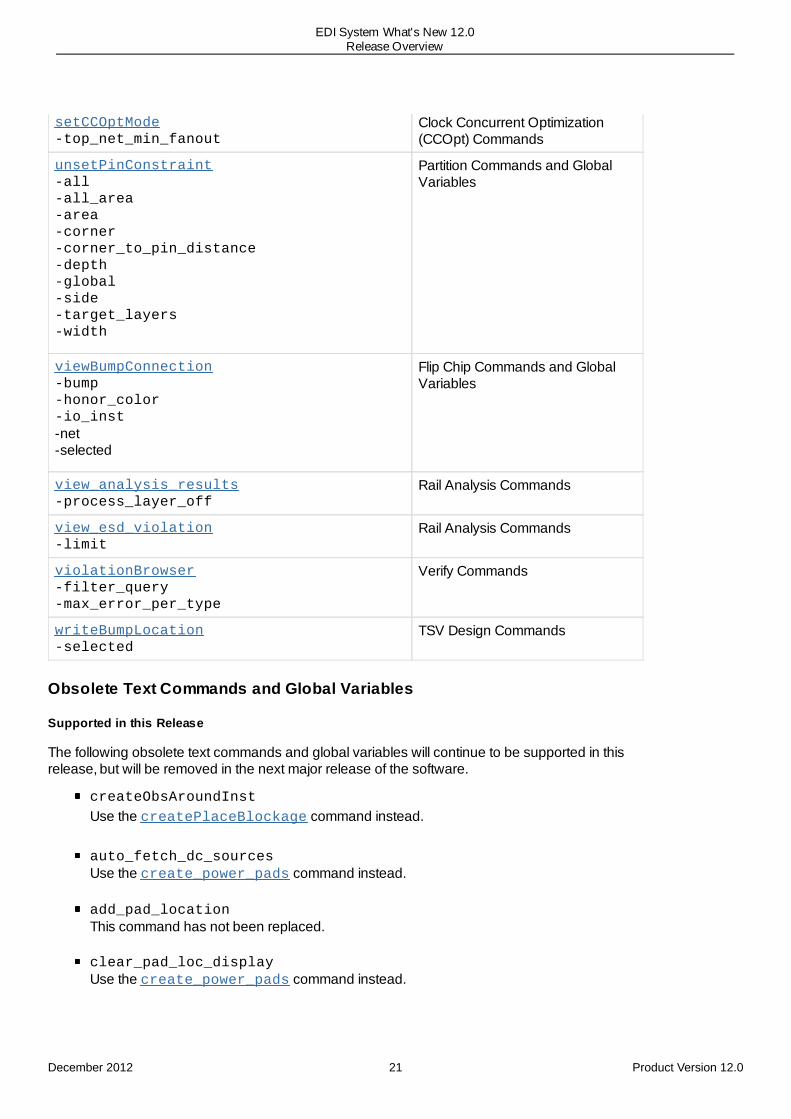
setCCOptMode-top_net_min_fanout
Clock Concurrent Optimization(CCOpt) Commands
unsetPinConstraint-all-all_area-area-corner-corner_to_pin_distance-depth-global-side-target_layers-width
Partition Commands and GlobalVariables
viewBumpConnection-bump-honor_color-io_inst-net-selected
Flip Chip Commands and GlobalVariables
view_analysis_results-process_layer_off
Rail Analysis Commands
view_esd_violation-limit
Rail Analysis Commands
violationBrowser-filter_query-max_error_per_type
Verify Commands
writeBumpLocation-selected
TSV Design Commands
Obsolete Text Commands and Global Variables
Supported in this Release
The following obsolete text commands and global variables will continue to be supported in thisrelease, but will be removed in the next major release of the software.
createObsAroundInst
Use the createPlaceBlockage command instead.
auto_fetch_dc_sourcesUse the create_power_pads command instead.
add_pad_locationThis command has not been replaced.
clear_pad_loc_displayUse the create_power_pads command instead.
December 2012 21 Product Version 12.0
EDI System What's New 12.0Release Overview
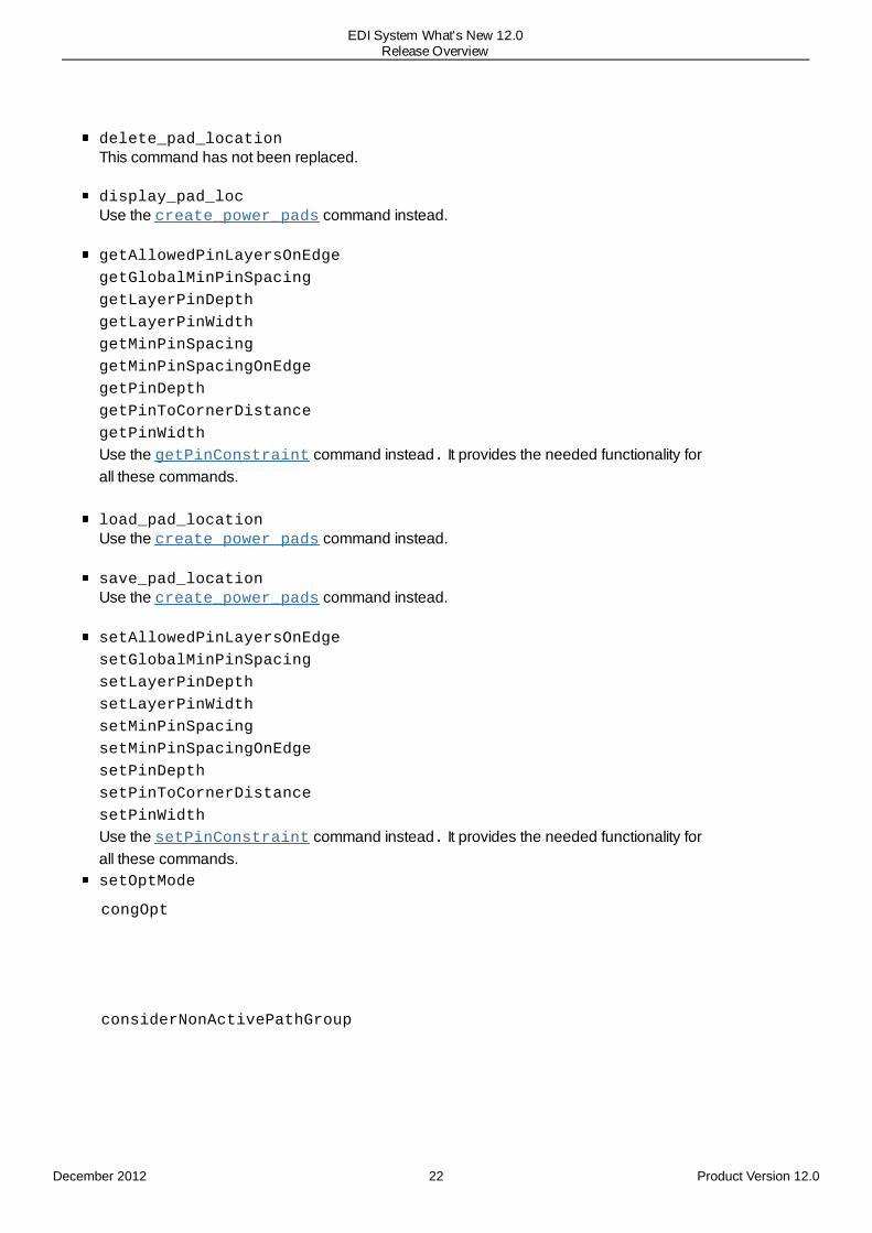
delete_pad_locationThis command has not been replaced.
display_pad_locUse the create_power_pads command instead.
getAllowedPinLayersOnEdge getGlobalMinPinSpacing getLayerPinDepth getLayerPinWidth getMinPinSpacing getMinPinSpacingOnEdge getPinDepth getPinToCornerDistance getPinWidth
Use the getPinConstraint command instead. It provides the needed functionality forall these commands.
load_pad_locationUse the create_power_pads command instead.
save_pad_locationUse the create_power_pads command instead.
setAllowedPinLayersOnEdge setGlobalMinPinSpacing setLayerPinDepth setLayerPinWidth setMinPinSpacing setMinPinSpacingOnEdge setPinDepth setPinToCornerDistance setPinWidth
Use the setPinConstraint command instead. It provides the needed functionality forall these commands.setOptMode
congOpt
considerNonActivePathGroup
December 2012 22 Product Version 12.0
EDI System What's New 12.0Release Overview
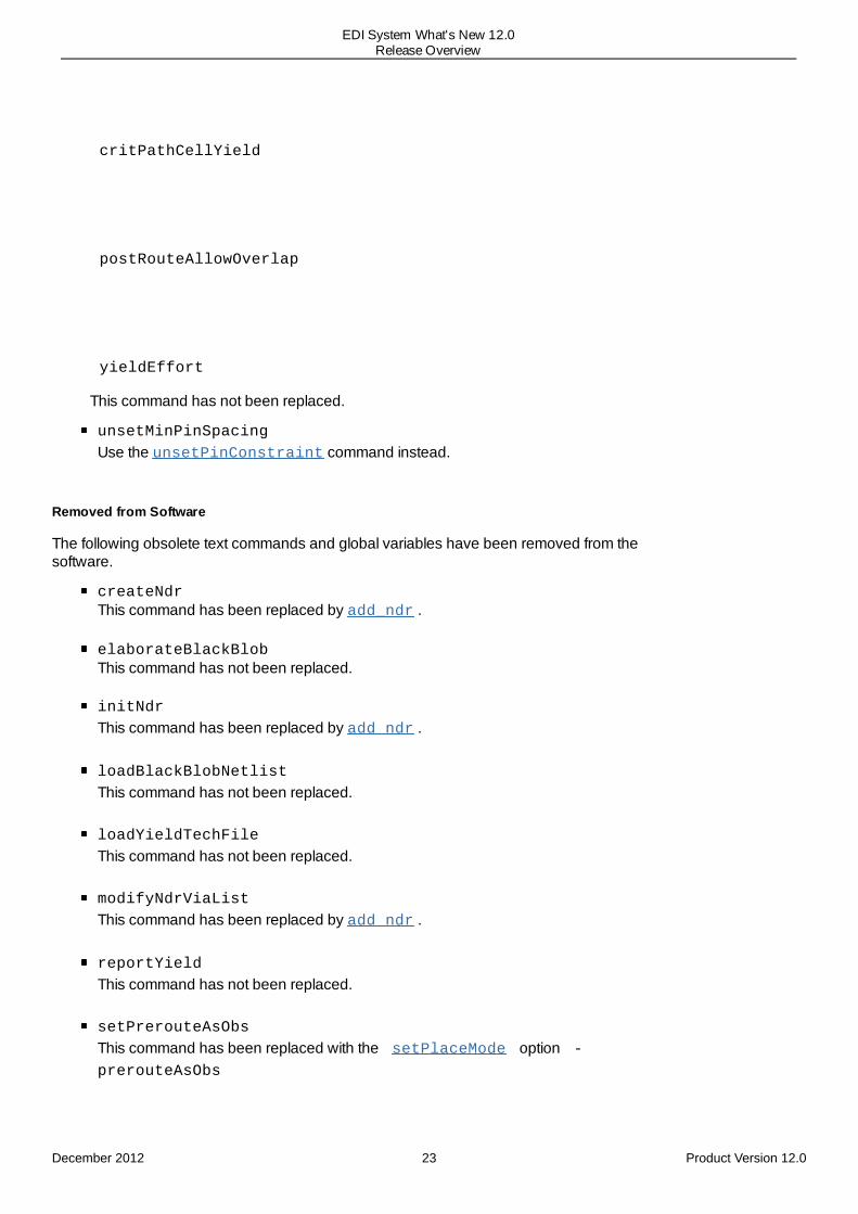
critPathCellYield
postRouteAllowOverlap
yieldEffort
This command has not been replaced.
unsetMinPinSpacing
Use the unsetPinConstraint command instead.
Removed from Software
The following obsolete text commands and global variables have been removed from thesoftware.
createNdrThis command has been replaced by add_ndr .
elaborateBlackBlobThis command has not been replaced.
initNdr
This command has been replaced by add_ndr .
loadBlackBlobNetlist
This command has not been replaced.
loadYieldTechFile
This command has not been replaced.
modifyNdrViaList
This command has been replaced by add_ndr .
reportYield
This command has not been replaced.
setPrerouteAsObs
This command has been replaced with the setPlaceMode option -prerouteAsObs
December 2012 23 Product Version 12.0
EDI System What's New 12.0Release Overview

setNdrSpacing
This command has been replaced by add_ndr .
setNdrWidth
This command has been replaced by add_ndr .
specifyBlackBlob
This command has not been replaced.
unplaceBlackBlob
This command has not been replaced.
unspecifyBlackBlob
This command has not been replaced.
Obsolete Command Parameters
Supported in this Release
The following obsolete text command parameters will continue to be supported in this release, butwill be removed in the next major release of the software. Update your scripts to avoid warningsand to ensure compatibility with future releases.
checkPinAssignment
-busGuideCheck
-netGroupCheck -pinAbutmentCheck
-pinDepthCheck
-pinGroupCheck
-pinGuideCheck
-pinLayerCheck
-pinMinAreaCheck
-pinOnFenceCheck
-pinOnTrackCheck
-pinSpacingCheck
-pinWidthCheck
Use -ignore {bus_guide net_group pin_abutment pin_depthpin_group pin_guide pin_layer pin_min_area pin_on_fence
pin_on_track pin_spacing pin_width clones} instead.
optPowerSwitch -reportViolationsOnly
Use -reportOnly instead.
-unchainByInstances
The -unchainByInstances parameter of the addPowerSwitch command has been
December 2012 24 Product Version 12.0
EDI System What's New 12.0Release Overview

replaced by commandrechainPowerSwitch.
-chainByInstances
The -chainByInstances parameter of the addPowerSwitch command hasbeen replaced by the command rechainPowerSwitch parameter -chainByInstances.
-powerDomainBufList
The -powerDomainBufList parameter of the bufferTreeSynthesis commandwill be removed in the next release. You can specify both always-on and regular buffers inthe buffer list. bufferTreeSynthesis will be able to pick up the right buffer.
-srpgEnablePins
The -srpgEnablePins parameter of the bufferTreeSynthesis command willbe removed in the next release. optDesign is able to optimize the always-on netsautomatically.
getVerifyGeometryMode -minPinArea
setVerifyGeometryMode -minPinArea
verifyGeometry -minPinArea
Use the -sameCellViol parameter of these commands instead to report minimum areaviolations for pin shapes in the cell, along with other cell violations.
getVerifyGeometryMode -warning
setVerifyGeometryMode -warningverifyGeometry -warningThis parameter is not being replaced as Verify Geometry does not write warning markers.
runN2NOpt -optimizeYield
This parameter is not being replaced as the Yield Analysis feature is becoming obsolete.
read_activity_file -scale_tcf_duration, -scale_fsdb_duration,and -scale_vcd_duration.Use -scale_duration instead.
read_activity_file -fsdb_block, -tcf_block, and -vcd_block.Use -block instead.
read_activity_file -fsdb_scope, -tcf_scope, and -vcd_scope.Use -scope instead.
Removed from the Software
The following obsolete text command parameters have been removed from the software.
fcroute
December 2012 25 Product Version 12.0
EDI System What's New 12.0Release Overview

-allowOverCongestion
This parameter is not being replaced.
-balancePairThreshold
Use the THRESHOLD keyword in the DIFFPAIR section of the constraint file.
-connectPowerCellToBump
Use setFlipChipMode -connectPowerCellToBump instead.
-differentialPairRoute
Specify the pair of nets in the DIFFPAIR section of the constraint file.
-differentialRoute
Use the exta configuration file optionsrouteDifferentialRouteTolerance instead.
-differentialRouteTolerance
Use the TOLERANCE keyword in the MATCH section of the constraint file instead.
-interleaveStyle
Use SPLITSTYLE keyword in the constraint file instead.
-multiBumpsToPad
Use setFlipChipMode -multipleConnection multiBumpsToPad instead.
-multiPadsToBump
Use setFlipChipMode -multipleConnection multiPadsToBump instead.
-optWidth
Use the exta configuration file option srouteGrouteOptimizeWidth instead.
-preventViaUnderBump
Use setFlipChipMode -prevent_via_under_bump instead.
-routeStyle
Use setFlipChipMode -route_style instead.
-shieldBump
Use the SHIELDBUMP keyword in the SHIELDING section of the constraint file instead.
-shieldLayers
Use the SHIELDSTYLE keyword in the SHIELDING section of the constraint file instead.
-shieldNet
Use the SHIELDNET keyword in the SHIELDING section of the constraint file instead.
December 2012 26 Product Version 12.0
EDI System What's New 12.0Release Overview
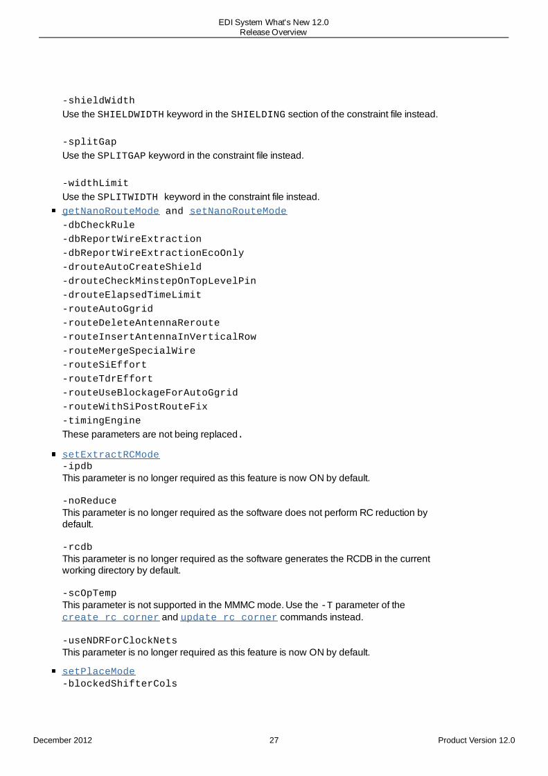
-shieldWidth
Use the SHIELDWIDTH keyword in the SHIELDING section of the constraint file instead.
-splitGap
Use the SPLITGAP keyword in the constraint file instead.
-widthLimit
Use the SPLITWIDTH keyword in the constraint file instead.getNanoRouteMode and setNanoRouteMode -dbCheckRule
-dbReportWireExtraction
-dbReportWireExtractionEcoOnly -drouteAutoCreateShield -drouteCheckMinstepOnTopLevelPin -drouteElapsedTimeLimit -routeAutoGgrid -routeDeleteAntennaReroute -routeInsertAntennaInVerticalRow -routeMergeSpecialWire -routeSiEffort -routeTdrEffort -routeUseBlockageForAutoGgrid -routeWithSiPostRouteFix -timingEngine
These parameters are not being replaced.
setExtractRCMode-ipdbThis parameter is no longer required as this feature is now ON by default.
-noReduceThis parameter is no longer required as the software does not perform RC reduction bydefault.
-rcdbThis parameter is no longer required as the software generates the RCDB in the currentworking directory by default.
-scOpTempThis parameter is not supported in the MMMC mode. Use the -T parameter of thecreate_rc_corner and update_rc_corner commands instead.
-useNDRForClockNetsThis parameter is no longer required as this feature is now ON by default.
setPlaceMode-blockedShifterCols
December 2012 27 Product Version 12.0
EDI System What's New 12.0Release Overview
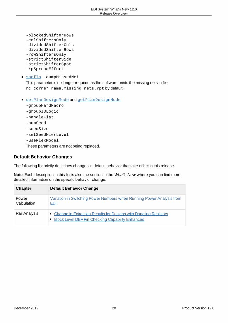
-blockedShifterRows-colShiftersOnly-dividedShifterCols-dividedShifterRows-rowShiftersOnly-strictShifterSide-strictShifterSpot-rpSpreadEffort
spefIn -dumpMissedNet
This parameter is no longer required as the software prints the missing nets in filerc_corner_name.missing_nets.rpt by default.
setPlanDesignMode and getPlanDesignMode-groupHardMacro
-groupIOLogic
-handleFlat
-numSeed
-seedSize
-setSeedHierLevel
-useFlexModel
These parameters are not being replaced.
Default Behavior Changes
The following list briefly describes changes in default behavior that take effect in this release.
Note: Each description in this list is also the section in the What's New where you can find moredetailed information on the specific behavior change.
Chapter Default Behavior Change
PowerCalculation
Variation in Switching Power Numbers when Running Power Analysis fromEDI
Rail Analysis Change in Extraction Results for Designs with Dangling ResistorsBlock Level DEF Pin Checking Capability Enhanced
December 2012 28 Product Version 12.0
EDI System What's New 12.0Release Overview
3
Licensing Changes for Release 12Release 12.0 Enhancements
Product Changes for 20nm SupportMulti-CPU Acceleration Tokens for ETS-XL Changed to Four
Release 12.0 Enhancements
Product Changes for 20nm SupportThe product options ENC-T20 and ENC-S20 are now allowed to be checked out dynamically fromFE-L and FE-XL. If FE is used to load a lef with 20nm rules, one of the 20nm option licenses ischecked out.
For more information, see Checking Out Licenses for Product Options in the Product andLicensing Information chapter of the EDI System User Guide.
Multi-CPU Acceleration Tokens for ETS-XL Changed to FourIn this release, the multi-CPU acceleration tokens for ETS-XL has been increased to four. Thismeans that a base license for ETS-XL now enables four CPUs. Moreover, each additional multi-CPU license for ETS-XL enables four more CPUs for acceleration.
December 2012 29 Product Version 12.0
EDI System What's New 12.0Licensing Changes for Release 12
4
Foundation FlowsRelease 12.0 Enhancements
New Variables for Foundation FlowSupport for Power Domain - Delay Corner Binding ViaHierarchical Two-Pass Automated Re-budgeting Flow Extended
Release 12.0 Enhancements
New Variables for Foundation FlowThe new variables in this release of Foundation Flows are:
vars(oa_fp): to be used for OA floorplan support.set vars(enable_dlm) true | false : Enables new flex ILM hierarchical flowset vars(enable_celtic_steps) true | false : Enable the Celtic SI fixing steps(Default: Off in 12.0)
Support for Power Domain - Delay Corner Binding Via
Foundation Flows now supports power domains. The variables are:
set vars(library_sets): List of library setsset vars(delay_corners): List of delay cornersset vars(power_domains): List of power domains to bindset vars(dc,power_domains): List of power domainsset vars(dc,ls,power_domains): List of power domains. This allows bind to aspecify delay corner AND library set
Hierarchical Two-Pass Automated Re-budgeting Flow ExtendedEDI System Foundation Flow extends the two-pass hierarchical flow to include automated ILM andFlexILM-based re-budgeting flow for regular implementation of the flow.
December 2012 30 Product Version 12.0
EDI System What's New 12.0Foundation Flows
5
EDI System Display and ToolsRelease 12.0 Enhancements
Ruler EnhancementsNew and Enhanced Ruler ModesTotal Ruler Length DisplayAuto Snap to Object EdgesCustom Colors
Enhancements in Pin Display and SelectionNew Option for Viewing Enlarged Logical PinsNew Pin Shapes Option in Layer Control Bar New Option for Highlighting Pin Shapes on Net Selection
Enhancements in Flightline PreferencesNew Option for Displaying Only Clock NetsNew Options for Controlling Flightline Color and Width
Enhancement in the Ungroup FeatureLog File Enhancementfind_global Enhancementset_object_color EnhancementNew Command for Limiting Display of Return ValuesNew Command To Launch DB BrowserNew Form for Going to a Specific LocationNew DBTCL OptionNew Command to Control Message Severity Level
Release 12.0 Enhancements
Ruler EnhancementsIn this release, the following enhancements have been made to the ruler to make it easier to use:
New and Enhanced Ruler Modes
In this release, existing ruler modes have been reorganinzed and new ruler modes have beenintroduced to make the ruler easier to use. The following ruler modes are now available in theCreate Ruler Preferences form:
RulerMode
Purpose Old ModesReplaced
Singleedge
Specifies that ruler line can be drawn in a single direction. This isthe default ruler mode.
Use this option if you want to measure a single edge in one of thefollowing directions:
VerticalHorizontalDiagonal (45 degrees, 135 degrees)Any angle
To draw a vertical, horizontal, or diagonal (45 or 135 degrees)ruler, simply click at the point where you want the ruler to start andmove the mouse in the required direction. The ruler line will followone of the following defined directions automatically.
VerticalHorizontalAnyAngles45135X
December 2012 31 Product Version 12.0
EDI System What's New 12.0EDI System Display and Tools

To draw a ruler at an angle other than the above eight directions,keep the Shift key pressed and then start drawing the ruler atthe required angle.
To end a Single edge ruler, either click at the point where youwant to end the ruler or press Enter.
Orthogonaledges
Specifies that ruler lines can be drawn in horizontal as well asvertical directions. Use this option if you want to measureorthogonal edges, such as follows:
Note: You can draw an Orthogonal ruler without opening theCreate Ruler Preferences form. Just keep the Ctrl key pressedand then start drawing the ruler to measure orthogonal edges. Toend the ruler, press Enter.
Orthogonal
Multipleedges
Specifies that ruler lines can be turned in multiple directions. Usethis option if you want to measure multiple segments in a complexpattern.
To draw a Multiple edge ruler, click at the point where you wantthe ruler to start. Move the mouse in the required direction, clickingat evey point you want the ruler to turn. To end the ruler, pressEnter .
Note: To draw a ruler in a direction other than horizontal, verticalor diagonal (45 or 135 degrees), keep the Shift key pressedand then start drawing the ruler at the required angle.
-
CrossRuler
Specifies that ruler lines can be drawn in a + shape. Use thisoption to measure two edges at the same time, see the overall X
-
December 2012 32 Product Version 12.0
EDI System What's New 12.0EDI System Display and Tools

and Y length, or to check alignment of macros.
To draw a cross ruler, click anywhere in the design. A + ruler isdisplayed occupying the entire display area in both X and Ydirections. The center of the + moves with the cursor. Move thecenter of the + to the point where you want the origin of the ruler.Press Enter to place and end the ruler.
You can access the Create Ruler Preferences form either by choosing Tools - Create Ruler orclicking the Create Ruler widget and press the F3 key.
Total Ruler Length Display
You can now easily view the total length of your ruler. As soon as you end a ruler, its total length isdisplayed alongside, in additon to the length of the individual segments of the ruler.
Auto Snap to Object Edges
In this release, edge detection has been enhanced so that a ruler can automatically snap to anobject’s edges or corners.
Custom Colors
You can now change the color of the ruler from the default yellow to any color of your choice. Inthe color preferences form, click the color box next to Ruler on the View-Only page and choosethe desired color.
Enhancements in Pin Display and Selection
New Option for Viewing Enlarged Logical Pins
Use the new Enlarge Logical Pin In Fit View option on the Display page of the Preferences formto check pin distribution in a block design. When this option is selected, the tool displays largersymbols for logical pins in the Fit view. This is helpful for feedthrough planning as it gives you anapproximate idea of where pins are dense and where spaces exist for feedthrough pins in thedesign. As you zoom into the design, the logical pin view gradually disappears and the realphysical pin locations are shown in the zoomed-in view.
December 2012 33 Product Version 12.0
EDI System What's New 12.0EDI System Display and Tools

New Pin Shapes Option in Layer Control Bar
You can now control whether pin shapes are visible and selectable by using the Pin Shapesoption under Cell in conjunction with the Terminal option under Miscellaneous on the LayerControl bar.
Instance pin/term display behavior has been modified as follows:
Terminal VisibilityToggle
Pin Shape VisibilityToggle
Main Window Displays
On (Default) Off (Default) Yellow squares (Representing instanceterms)
December 2012 34 Product Version 12.0
EDI System What's New 12.0EDI System Display and Tools

On On Pin shape
Off On Pin shape
Off Off Null
You can get a pin's instance terminal (InstTerm) information by selecting the pin and then runningthe dbGet selected command.
New Option for Highlighting Pin Shapes on Net Selection
In this release, a new selection preference option has been added to view connected cell termshapes when you select a net. If the new Hilite Pin Shapes When Selecting a Net option on theSelection page of the Preferences form is turned on, all visible cell term shapes are highlightedwhen you select a net.
Enhancements in Flightline Preferences
New Option for Displaying Only Clock Nets
By default, EDI System shows the flightlines of all nets. However, during floorplanning, you mightwant to place the hierarchical module and focus on checking the connectivity of clock and resetnets based on flightlines. You can now select the new Show Clock Net Only option on theFlightline page of the Preferences form to view the flightlines of only clock and reset nets.
New Options for Controlling Flightline Color and Width
By default, EDI System displays all flightlines in blue color. In previous releases, you could chooseto use different colors for input, output, and inout connections. In this release, EDI System providesyou additonal options to control flightline color and width based on the number of connections.You can now choose from the following Flightline Color Control options:
Single Color: Uses a single color for all flightlines.Default: Blue
Different Color by Type of Connections: Displays the input, output, and inout netconnections using different colors.
Input - GreenOutput - YellowInout - PinkMixture - Blue
Different Color by Number of Connections: Displays small, medium, and large number of
December 2012 35 Product Version 12.0
EDI System What's New 12.0EDI System Display and Tools
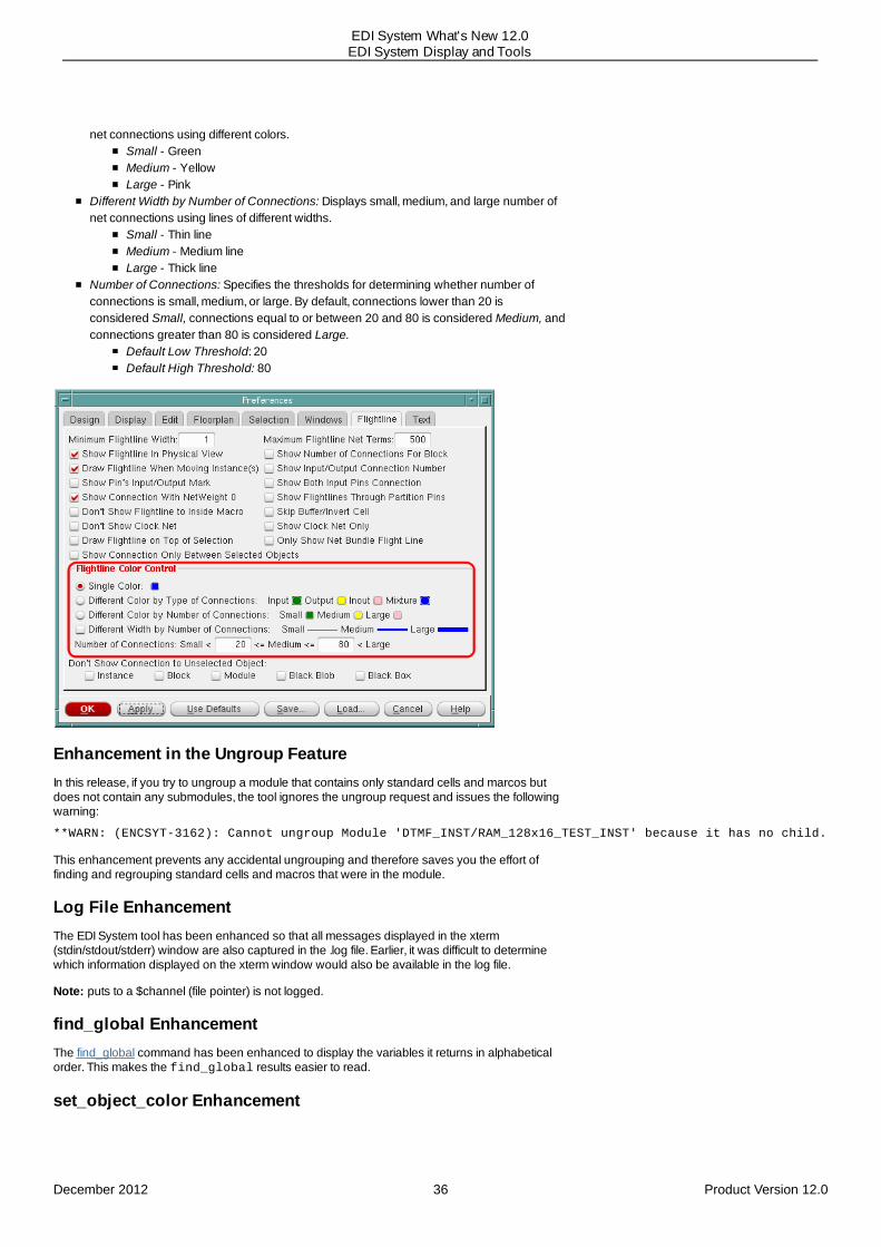
net connections using different colors.Small - GreenMedium - YellowLarge - Pink
Different Width by Number of Connections: Displays small, medium, and large number ofnet connections using lines of different widths.
Small - Thin lineMedium - Medium lineLarge - Thick line
Number of Connections: Specifies the thresholds for determining whether number ofconnections is small, medium, or large. By default, connections lower than 20 isconsidered Small, connections equal to or between 20 and 80 is considered Medium, andconnections greater than 80 is considered Large.
Default Low Threshold: 20Default High Threshold: 80
Enhancement in the Ungroup FeatureIn this release, if you try to ungroup a module that contains only standard cells and marcos butdoes not contain any submodules, the tool ignores the ungroup request and issues the followingwarning:
**WARN: (ENCSYT-3162): Cannot ungroup Module 'DTMF_INST/RAM_128x16_TEST_INST' because it has no child.
This enhancement prevents any accidental ungrouping and therefore saves you the effort offinding and regrouping standard cells and macros that were in the module.
Log File EnhancementThe EDI System tool has been enhanced so that all messages displayed in the xterm(stdin/stdout/stderr) window are also captured in the .log file. Earlier, it was difficult to determinewhich information displayed on the xterm window would also be available in the log file.
Note: puts to a $channel (file pointer) is not logged.
find_global EnhancementThe find_global command has been enhanced to display the variables it returns in alphabeticalorder. This makes the find_global results easier to read.
set_object_color Enhancement
December 2012 36 Product Version 12.0
EDI System What's New 12.0EDI System Display and Tools

The set_object_color command is used to set the color of objects of an instance, hierarchicalinstance, SDP, or module. In this release, the set_object_color command has beenenhanced to support power domains and instance groups as well. You can now useset_object_color -object_name to set the color of objects of a specific power domain orinstance group. Alternatively, you can use set_object_color -object_type to set thecolor of all power domain objects or instance group objects. For example, use the followingcommand to color all power domain objects in multiple colors:
set_object_color -object_type PowerDomain -multicolor
New Command for Limiting Display of Return ValuesYou can now use the new set_return_limit command to control the display of Tcl return values inscreen output or log file.
Impact on Other Commands, Parameters, and Globals: None
New Command To Launch DB BrowserIn this release, you can use the new db_browser command to launch the DB Browser and retrieveinformation about various database objects. In previous releases, you could launch the browseronly from the GUI or by using the v bindkey.
Impact on Other Commands, Parameters, and Globals: None
New Form for Going to a Specific LocationUse the new Goto form to find specific locations accurately in the main window display. Youcan specify one or more sets of X and Y coordinates either directly in the form or by loading a file.You can then click the Goto button to create an X marker on the location specified by the selectedcoordinates and zoom into that location in the main window display. By creating additionalmarkers for other locations in the list, you can view relative locations of multiple sets of X and Ycoordinates.
New DBTCL OptionThe command dbShape now supports the parameter -maxPoint which helps specifythe maximum number of points for output in a polygon. The minimum being 5 and maximum 8000.
New Command to Control Message Severity LevelYou can now use the set_message command to change the message severity level, INFO,WARNING or ERROR, at the beginning of the message. This command allows you to control themessages that are displayed for a particular design. For example, if there are some warnings thatare critical for the design, you can change the message severity to ERROR. Similarly, if there aremessages that you want to ignore, you can change the message severity to INFO. The syntax ofthe command is given below:
set_message[-help][-id list_of_msgIDs]
December 2012 37 Product Version 12.0
EDI System What's New 12.0EDI System Display and Tools

-severity {warn error info reset}
December 2012 38 Product Version 12.0
EDI System What's New 12.0EDI System Display and Tools

6
Multiple CPU ProcessingRelease 12.0 Enhancements
Memory Reporting Improved
Release 12.0 Enhancements
Memory Reporting ImprovedIn this release, memory reporting has been improved to indicate how much memory is being usedat any time and of what form (physical, virtual, and master/slave). Previously, peak memory wasthe only number which had some physical significance. You can now use the -verboseparameter of the report_resource command to get detailed memory usage information.
When you run report_resource -verbose, the following detailed memory information isdisplayed:
Current (total cpu=0:00:12.9, real=0:05:48, peak res=275.8M,current mem=383.9M)
Cpu(s) 2, load average: 4.63
Mem: 16443800k total, 16378412k used, 65388k free, 105704k buffers
Swap:16777208k total, 17460k used, 16759748k free, 12528212kcached
Memory Detailed Usage:
Data ResidentSet(DRS)
PrivateDirty(DRT)
VirtualSize(VIRT)
ResidentSize(RES)
Totalcurrent:
383.9M 275.8M 854.1M 358.9M
peak: 383.9M 275.8M 854.1M 358.9M
The -verbose parameter also works in conjunction with the -peak and -start/-endparameters of the report_resource command. When you run the local distributed slave(setDistributeHost -local) command, the memory information will include the memoryconsumed by master and slaves.
December 2012 39 Product Version 12.0
EDI System What's New 12.0Multiple CPU Processing

For -start/-end parameters, use -verbose with the -end parameter only.
For details on memory information, refer to the Accelerating the Design Process By Using Multiple-CPU Processing chapter of the EDI System User Guide.
Impact on Other Commands, Parameters, and Globals: None
December 2012 40 Product Version 12.0
EDI System What's New 12.0Multiple CPU Processing

7
Importing and Exporting the DesignRelease 12.0 Enhancements
lefOut and defOut Enhanced To Support Embedded BumpslefOut Enhanced To Output PG Bump Information along with PG Physical PinsNew Global Variable To Uniquify the DesignNew Global Variable for Power RoutingNew Options for Command add_shape
Release 12.0 Enhancements
lefOut and defOut Enhanced To Support Embedded BumpsIn previous releases, when you use lefOut to export a multi-block design, the bumps in each blockare described as PIN in the export LEF file. This makes it difficult to distinguish bumps from normalpins. When you are implementing a hierarchical flow in a 3DIC design, the tool needs to export allthe bump information in each chip correctly. This is because all embedded bump metal layerinformation is required for analysis in top-level RC extraction.
In this release, the PASSIVATION layer is used to define an embedded bump in the block. If aPORT in a block has a PASSIVATION layer, the tool treats it as an embedded bump. lefOut hasbeen enhanced to output both metal layer and PASSIVATION layer information for the embeddedbump to the LEF file. In addition, the defOut -bumpAsPin option has been enhanced to catchembedded bumps and output all their layer information (metal layers as well as PASSIVATIONlayer geometry) in the PIN section of the DEF file in the same way as for normal bumps.
lefOut Enhanced To Output PG Bump Information along with PGPhysical PinsIn previous releases, if your block-level design had both Power/Ground (PG) physical pins and PGbumps, lefOut would print only the physical pin geometry to the block LEF file. lefOut has nowbeen enhanced to outpout both PG bump and PG physical pin information. This is useful if youwant to import the block LEF files in a third-party tool and need the PG bump geometry as well asthe PG physical pin information for top level connections.
New Global Variable To Uniquify the DesignIn this release, the rda_Input(ui_uniquify_netlist) variable has been replaced withthe new init_design_uniquify global variable in accordance with the init_design model introduced
December 2012 41 Product Version 12.0
EDI System What's New 12.0Importing and Exporting the Design

in EDI11. You can use the init_design_uniquify global variable to uniquify the designautomatically during the read and flatten process.
New Global Variable for Power RoutingIn this release, you can use the new init_oa_special_rule variable to specify the OpenAccessconstraint group that defines the vias to be used by SROUTE. If nothing is specified, then theconstraint group with the nameLEFSpecialRouteSpec is searched in OpenAccess.
New Options for Command add_shapeA few new options have been added to the command add_shape. They are, as follows:
-shape: Defines the wiring shape.-shield_net: The name or pointer of the net to be shielded by the via instance.-status: Defines the wiring status.-user_class: Defines the attribute class by user.
December 2012 42 Product Version 12.0
EDI System What's New 12.0Importing and Exporting the Design
8
LEF-DEF PropertiesRelease 12.0 Enhancements
LEF 5.8 Properties for Creating New DRC Rules for 32-28nm and Smaller NodesCut Layer Enhancements
You can define new CUT LAYER properties to create rules for cut layers that:
Add ANTENNAGATEPWL rule, to define a PWL (piece-wise linear) table that is indexed bythe real gate area, and returns an “effective gate-area” interpolated from the table. If thetable it not defined, the real gate area is used.
Add BELOWENCLOSURE in PARALLEL to cut layer ENCLOSURE rules, to indicate that theenclosure rule only applies if the enclosure on the below metal layer is less than thespecified below enclosure value on either sides perpendicular to the side having neighborsor the wire direction containing the cut on the above metal layer.
Add parLength2 in PARALLEL and parWithin2 in WITHIN to cutlayer ENCLOSURE rules, to indicate that the rule does not apply if there is no neighbor oneither side based on parWithin2 and parLength2. The variable parLength2 must be smallerthan parLength and parWithin2 must be larger than parWithin.
The following cut layer enhancements have been made:
Enhanced ANTENNAGATEPLUSDIFF rule, to represent the protection provided bythe diffusion area that is added to the gate area value in the PAR (partial antennaratio) equation, which can be considered as the “additional effective gate-area”.
Enhanced PARALLEL in CONCAVECORNER in cut layer SPACING rules. Anenclosure can now be on one of the two opposite sides on the specified secondlayer. Earlier, the enclosure could be defined on both the two opposite sides of alayer.
For more information, see Defining Cut Layer Properties to Create 32/28 nm and Smaller NodesRules in the "LEF Syntax" chapter of the LEF/DEF Language Reference Guide.
December 2012 43 Product Version 12.0
EDI System What's New 12.0LEF-DEF Properties

Routing Layer Enhancements
You can define new ROUTING LAYER properties to create rules for routing layers that:
Add JOINTCORNERSPACING rule, to indicate that the spacing between two facing jointsof joint corners with parallel run length less than zero to be the spacing.
Add ENCLOSURESPACING rule, to specify the spacing on an edge with enclosure lessthan the specified enclosure.
Add ANTENNAGATEPWL rule, to define a PWL (piece-wise linear) table that is indexed bythe real gate area, and returns an “effective gate-area” interpolated from the table. If thistable it not defined, the real gate area is used.
Add CONCAVECORNERS in NOADJACENTEOL to routing layer MINSTEP rules, to indicatethat the adjacent EOL minimum step rules only apply if both the neighbor edges of the EOLhave concave corner on the other end.
Add following keywords to routing layer OPPOSITEEOLSPACING rules:JOINTEXTENSION in JOINTWIDTH: Specifies the extension on both sides of ajoint to be the joint extension.JOINTCORNERONLY in JOINTWIDTH : Specifies that the joint must form a jointcorner, which is a convex corner consisting of two consecutive joints.SIDEEDGELENGTH in WIDTH: Specifies that a side fulfilling other conditions mustalso on an edge with length greater than the specified side edge length.JOINTTOSIDE: Specifies a spacing requirement similar to SIDETOJOINT, buthaving joint spacing to be the first spacing. SIDETOSIDE: Specifies a spacing requirement between two sides of an EOL edgewith a middle wire.
Add SAMEMASK to routing layer EOLEXTENSIONSPACING rules, to specify that the EOLextension spacing only applies to same-mask objects.
Add the following new variables and keywords to routing layer FORBIDDENSPACINGrules:
minSpacing2 and maxSpacing2, to define an additional second set of forbiddenspacing range.
TWOEDGES in WIDTH, to indicate that the forbidden spacing only applies if the wirewidth is less than the maximum width that has neighbors on both sides within thespecified within value.
December 2012 44 Product Version 12.0
EDI System What's New 12.0LEF-DEF Properties

The following routing layer enhancements have been made:
Enhanced ANTENNAGATEPLUSDIFF rule, for protection provided by the diffusion areathat is added to the gate-area value in the PAR equation, which can be considered as“additional effective gate-area”.
For more information, see Defining Routing Layer Properties to Create 32/28 nm and SmallerNodes Rules in the "LEF Syntax" chapter of the LEF/DEF Language Reference Guide.
December 2012 45 Product Version 12.0
EDI System What's New 12.0LEF-DEF Properties
9
Wire EditingRelease 12.0 Enhancements
New setSpecialRouteOption options for Supporting Multiple-Layer P/G PinsNew Option for Selecting/Deselecting Via along with WireNew setViaEdit Option for Creating Special ViasNew setViaEdit Option To Prevent Replacement of Existing Via with New,Overlapping ViaNew setEdit Option for Stretching Wires Along with Via
Release 12.0 Enhancements
New setSpecialRouteOption options for Supporting Multiple-Layer P/G PinsEDI System now supports multiple-layer Power/Ground pins. In earlier releases, the mulitple-layerpin feature was only supported by signal pins. With this enhancement, you can generate multi-layer (two-layer) boundary pins for special wire.
To turn on the multi-layer P/G pin feature, you must set the new setSpecialRouteOption -multi_layer_pin option to 1. You can specify the name of the via cell on which you want tobase the multi-layer pin by using the new -multi_layer_via option ofthe setSpecialRouteOption command.
You can do the same from the GUI by using the highlighted options in the Special Route Optionsform. The Special Route Options form can be accessed by clicking the Options button in the EditRoute form:
December 2012 46 Product Version 12.0
EDI System What's New 12.0Wire Editing
Impact on Other Commands, Parameters, and Globals: None
New Option for Selecting/Deselecting Via along with WireEDI System now enables you to select or deselect a via along with the wire. This enhancementmakes it possible for you to perform certain operations on a wire and associated viasimultaneously. For instance, you can change the net of a wire and associated vias by firstselecting the wire and via with the editSelect command and then using the editChangeNetcommand to change the net.
Via selection/deselection happens by default when you select/deselect a wire. If you want toselect/deselect only the wire and not the associated via, use the new -wires_only option ofeditSelect and editDeselect, respectively.
Impact on Other Commands, Parameters, and Globals: If you specify the editSelect -wires_only option and then run editChangeNet, the net will be changed only for the wireand not for the via.
New setViaEdit Option for Creating Special ViasIn this release, you can use the new setViaEdit -force_special option to force editAddVia tocreate special vias instead of regular ones. This option is useful for flip chip flow in which all routingwire segments are special nets. In previous releases, if you added a via manually witheditAddVia and the connected pin was signal, a regular via was created and this via could notbe changed to a special via. The new setViaEdit -force_special option can now beused to ensure that the vias created with editAddVia are always special. You can do the samefrom the GUI by using the new Force Special option in the Edit Via form:
December 2012 47 Product Version 12.0
EDI System What's New 12.0Wire Editing
Impact on Other Commands, Parameters, and Globals: If you specify setViaEdit -force_special 1 and then run editAddVia, vias created will be always special. To createregular vias, specify setViaEdit -force_special 0 before running editAddVia.
New setViaEdit Option To Prevent Replacement of Existing Viawith New, Overlapping ViaYou can use the new setViaEdit -auto_replace option to control whether existing vias arereplaced with the new ones created using editAddVia in case of any overlap. You can alsouse the new Auto Replace option in the Edit Via form to control whether exisiting vias arereplaced.
Impact on Other Commands, Parameters, and Globals: If you specify setViaEdit -auto_replace 0 and then run editAddVia, existing vias will be retained even if there issome overalp with the new vias being added. Specify setViaEdit -auto_replace 1 toreplace existing vias with the new ones editAddVia in case of any overlap.
New setEdit Option for Stretching Wires Along with ViaUse the new setEdit -stretch_with_intersect option to stretch power wires with intersectseasily. If this option is set to 1, you can select the via and the edge of metals and then stretchthe wires and via together in a single step. In previous releases, the process for stretching wireswith intersects was more complex and required multiple steps.
December 2012 48 Product Version 12.0
EDI System What's New 12.0Wire Editing

Impact on Other Commands, Parameters, and Globals: None
December 2012 49 Product Version 12.0
EDI System What's New 12.0Wire Editing

10
Flip ChipRelease 12.0 Enhancements
Flip Chip Flightline EnhancementsHighlight by SelectionColored FlightlinesObject-Specific FlightlinesDIFFPAIR-Based HighlightingNew Display Flightline Form
Add Bump to Array Form Renamed and EnhancedNew changeBumpMaster ParametersNew Change Bump Master FormEnhanced Assign/Unassign Signals Form
New Auto Zoom FeatureNew Filter OptionsNew Criterion for Assigning Bumps
Support for Assigning Multiple PG Pads to Multi BumpsNew assignPGBumps ParameterNew Option for Flip Chip Routing in View AreaObsolete fcroute Parameters
Release 12.0 Enhancements
Flip Chip Flightline EnhancementsIn flip chip designs, flightlines are used extensively to interact with the design. You can display flipchip related flightlines using viewBumpConnection . In this release, flip chip flightlines havebeen enhanced in the following ways to make them more user-friendly:
Highlight by Selection
When you select an object, the corresponding flightlines are now highlighted in bold.
When a bump or IO pad is selected, its corresponding flightline is highlighted in bold.When multiple bumps/IO pads are selected, all their flightlines are highlighted in bold.If a block with multiple IO pins is selected, all its flightlines are highlighted in bold. When the objects are deselected, the corresponding flightlines return to non-bold status.
1. RunviewBumpConnection
to display all flip chipflightlines.
2. Click on an object tohighlight its flightline inbold.
December 2012 50 Product Version 12.0
EDI System What's New 12.0Flip Chip

Colored Flightlines
By default, all flip chip flightlines are displayed in yellow. You can now use the newviewBumpConnnection –honor_color option to color these flightlines based on eitherbump type or the nets to which the bumps are assigned:
To color flightlines by bump type, simply run viewBumpConnection –honor_color.The tool displays flightlines using the default colors of the bumps:
Blue for signal bumps Red for power bumps Yellow for ground bumps
To color flightlines based on the nets to which they are assigned, you must:
a. Define bump color settings in a bump color map file using the following format :net_name color_name
Example:int cyan
reset pink
b. Load the bump color file using the ciopLoadBumpColorMapFile command.
c. Run viewBumpConnection –honor_color.
For bumps whose nets are not defined in the bump color file, the default colors areused as follows--blue for signal bumps, red for power bumps, and yellow for groundbumps. A flightline has the same color as its bump.
Impact on Other Commands, Parameters, and Globals: If you want to assign custom colors toflightlines, you must specify the colors as required in the bump color map file andrun ciopLoadBumpColorMapFile before running viewBumpConnection –honor_color.
Object-Specific Flightlines
You can now easily view connections for specific objects, such as bumps, nets, and IO instances,using the following new viewBumpConnection parameters:
-bumps {bump_list}: Use this parameter to view connections of specified bumps. -io_inst {io_inst_list}: Use this parameter to view connections of specified IOinstances or blocks. -nets {net_list}: Use this parameter to view connections of specified nets. -selected: Use this parameter to view connections of selected bumps or IO pads inbold. If a block with multiple IO pins is selected, all its flightlines are displayed in bold.
December 2012 51 Product Version 12.0
EDI System What's New 12.0Flip Chip

For example, the following command displays the flightlines for the port_pad_data_out[10]net, the Bump_29 bump, and the IOPADS_INST/Ptdspop07 instance. It also displays in boldthe flightline for the selected bump:
viewBumpConnection \
-net {port_pad_data_out[10]} \
-bump Bump_29 \
-io_inst IOPADS_INST/Ptdspop07 \
-selected \
-honor_color
Impact on Other Commands, Parameters, and Globals: None
DIFFPAIR-Based Highlighting
Flip chip flightlines now honor the DIFFPAIR constraints specified in the flip chip router constraintfile. This means that when you select any one bump or IO pad that is part of a DIFFPAIRconstraint, the tool highlights all flightlines of that DIFFPAIR in bold.
For example, suppose the flip chip router constraint file, diffpair.const, has the followingsetting:
DIFFPAIR
port_pad_data_in[15]
port_pad_data_in[13]
END DIFFPAIR
Now after setFlipChipMode -constraintFile diffpair.const is set, the flightlinesfor the DIFFPAIR are highlighted in bold when any one bump or IO pad of the DIFFPAIR isselected:
December 2012 52 Product Version 12.0
EDI System What's New 12.0Flip Chip

Currently, you cannot turn off normal flightlines to focus on DIFFPAIR flightlines. However, you canuse viewBumpConnection –nets net_list as a workaround. Here, net_list specifiesnets of the DIFFPAIR. This way, you can display only the flightlines for the DIFFPAIR and turn off allother flightlines.
New Display Flightline Form
Use the new Display Flightline form to configure flip chip related flightlines from the GUI. Theoptions in this form are equivalent to viewBumpConnection options. You can access theDisplay Flightline form by choosing Tools - Flip Chip Toolbox - Display Flightline .
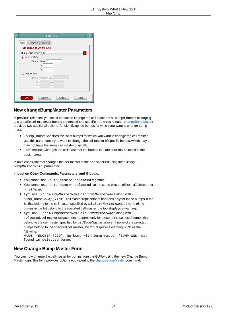
Add Bump to Array Form Renamed and EnhancedThe Add Bump to Array form has been renamed as Edit Bump. In addition, the form has beenenhanced to include three tabs:
Add - Use this page to add bumps to a bump array. This page provides the same optionsas the original Add Bump to Array form in previous releases. It is also equivalent to theaddBumpToArrayGrid command. Remove - Use this page to remove the selected or specified bump from its assigned bumparray grid. This page provides options equivalent to the removeBumpFromArraycommand.Delete - Use this page to to delete bumps from the design. This page provides optionsequivalent to the deleteBumps command.
December 2012 53 Product Version 12.0
EDI System What's New 12.0Flip Chip
New changeBumpMaster ParametersIn previous releases, you could choose to change the cell master of all bumps, bumps belongingto a specific cell master, or bumps connected to a specific net. In this release, changeBumpMasterprovides two additional options for identifying the bumps for which you want to change bumpmaster:
-bump_name: Specifies the list of bumps for which you want to change the cell master.Use this parameter if you want to change the cell master of specific bumps, which may ormay not have the same cell master originally. -selected: Changes the cell master of the bumps that are currently selected in thedesign area.
In both cases, the tool changes the cell master to the one specified using the existing -bumpMasterName parameter.
Impact on Other Commands, Parameters, and Globals:
You cannot use -bump_name or -selected together.You cannot use -bump_name or -selected at the same time as either -allBumps or -netName.If you use -fromBumpMasterName oldBumpMasterName along with -bump_name bump_list , cell master replacement happens only for those bumps in thelist that belong to the cell master specified by oldBumpMasterName . If none of thebumps in the list belong to the specified cell master, the tool displays a warning.If you use -fromBumpMasterName oldBumpMasterName along with -selected, cell master replacement happens only for those of the selected bumps thatbelong to the cell master specified by oldBumpMasterName . If none of the selectedbumps belong to the specified cell master, the tool displays a warning, such as thefollowing:WARN: (ENCSIP-7279): No bump with bump-master 'BUMP_GND' wasfound in selected bumps.
New Change Bump Master FormYou can now change the cell master for bumps from the GUI by using the new Change BumpMaster form. This form provides options equivalent to the changeBumpMaster command.
December 2012 54 Product Version 12.0
EDI System What's New 12.0Flip Chip

Enhanced Assign/Unassign Signals Form
In this release, the following enhancements have been made to the Assign/Unassign Signals formto make it easy for you to search for pads, bumps, or nets:
New Auto Zoom Feature
Use the new Auto Zoom check box to automatically zoom to the object selected in the Signal Listtable. This enhancement makes it easy for you to locate an IO signal in the display area.
New Filter Options
Use the Filter options to narrow down the list of signals displayed in the Signal List table. You canfilter the list by the following object types—IO Signal, Side, Driver, Driver Cell, Driver Pin, DriverLocation, Bump, or Bump Location. After you have selected the object type, specify a suitableOperator and Value and then click Filter. All objects that meet the specified criteria are listed in theSignal List table.
New Criterion for Assigning Bumps
You can now assign signals to a specified set of bumps by using the new In Bump Names option.You can specify the bump names manually in the In Bump Names text box. Alternatively, click
December 2012 55 Product Version 12.0
EDI System What's New 12.0Flip Chip

the Get Selected Bump button to compile the names of selected bumps in the text boxautomatically. After the required bump names are specified in the In Bump Names text box,click Assign to call the assignIOPinToBump command. This command assigns the signalshighlighted in the Signal List table to the specified bumps.
Assume that the number of IO Signal selected in the Signal List table is X and the number ofbumps specified in the In Bump Names text box is Y. The bump assignment happens as follows:
If X is equal to Y, the tool completes X assignments.If X is greater than Y, the tool displays a warning and assigns the first Y pins in selectionorder to the bumps.If X is smaller than Y, the tool displays a warning and assigns all pins to X bumps in thespecified order in the In Bump Names text box.
Support for Assigning Multiple PG Pads to Multi BumpsIn previous releases, the tool assigns one power and ground (PG) pad to one bump in the sameway as it assigns one signal pad to one bump. However, unlike signal pads, PG pads usuallyshare the same PG nets with each other. In this release, the tool can automatically assign multiplePG (multi-PG) pads on the same net to multiple bumps as per a controlled ratio that you define.Different PG nets can have different ratios. This enhancement not only saves a lot of bumpresource, it also requires less manual effort for bump assignment.
Use the new assignBump -ratio parameter to assign multiple PG pads to one bump.
For more information, see the Multi-PG Pads to Multi Bumps Assignment with a ControlledRatio section in the Flip Chip Methodologies chapter of the EDI System User Guide.
New assignPGBumps ParameterTill now, you could assign PG bumps in only two ways, horizontal and vertical. In this release, youcan use the new assignPGBumps -checkerboard parameter to assign PG bumps to thespecified pair of nets in a checkerboard pattern.
The -checkerboard parameter is to be used typically for a regular (rectangular) bump array.However, you can also it for an irregular (rectilinear) bump array. To do so, first form a regular arrayby creating virtual bumps in the areas where there are no bumps. Then, apply the checkboardpattern. Once you have assigned the bumps, you can remove the virtual bumps.
Impact on Other Commands, Parameters, and Globals: The checkerboard style can beused only with two nets. If -checkerboard is specified and the number of nets defined with -nets is more than two, the tool reports an error and does not assign any bumps.
New Option for Flip Chip Routing in View AreaPreviously, you could restrict flip chip routing to a specific portion of the design by either enteringthe exact coordinates or by interactively selecting the area in the design display window. In thisrelease, the Flip Chip Route form provides you another option of restricting routing with the click ofa button. When you click the new View Area button, the coordinates of the view area in thedesign display are automatically entered in the X1 Y1 X2 Y2 fields. This makes it easier for you tospecify the area to which you want to restrict flip chip routing.
December 2012 56 Product Version 12.0
EDI System What's New 12.0Flip Chip

Obsolete fcroute ParametersThe following fcroute parameters have been removed from the software. Update your scripts touse the suggested replacements.
Obsolete fcroute Parameter Suggested Replacement Syntax
-allowOverCongestion This option is not being replaced N/A
-balancePairThreshold Use the THRESHOLD keyword in theDIFFPAIR section of the constraint file.
DIFFPAIR
THRESHOLD valuenet_name_1 net_name_2
END DIFFPAIR
-connectPowerCellToBump Use setFlipChipMode -connectPowerCellToBump instead.
setFlipChipMode -connectPowerCellToBump true
-differentialPairRoute Specify the pair of nets in the DIFFPAIRsection of the constraint file.
DIFFPAIR
THRESHOLD valuenet_name_1 net_name_2
END DIFFPAIR
-differentialRoute Use the exta configuration file optionsrouteDifferentialRouteToleranceinstead.
srouteDifferentialRouteTolerance value
December 2012 57 Product Version 12.0
EDI System What's New 12.0Flip Chip

-differentialRouteTolerance Use the TOLERANCE keyword in the MATCHsection of the constraint file to specify thethreshold for differential routing
MATCH
TOLERANCE value net_name_1 net_name_2 ...
END MATCH
-interleaveStyle Use the SPLITSTYLE keyword in theconstraint file to specify the splitting style.
SPLITSTYLE RIVER | MESH
SPLITWID TH value
SPLITGAP value
SPLITKEEPTOTALWIDTH TRUE | FALSE
-multiBumpsToPad Use setFlipChipMode -multipleConnectionmultiBumpsToPad instead.
setFlipChipMode -multipleConnectionmultiBumpsToPad
-multiPadsToBump Use setFlipChipMode -multipleConnectionmultiPadsToBump instead.
setFlipChipMode -multipleConnectionmultiPadsToBump
-optWidth Use the exta configuration file optionsrouteGrouteOptimizeWidth instead. srouteGrouteOptimizeWidth TRUE
-preventViaUnderBump Use setFlipChipMode -prevent_via_under_bump instead.
setFlipChipMode -prevent_via_under_bump true
-routeStyle Use setFlipChipMode -route_style instead.
setFlipChipMode -route_style{manhattan | 45DegreeRoute}
-shield Bump Use the SHIELDBUMP keyword in theSHIELDING section of the constraint file tospecify whether bumps are to be shielded .
SHIELDING
SHIELDBUMP TRUE | FALSESHIELDWIDTH valueSHIELDGAP value SHIELDSTYLE a | b | cSHIELDNET netName<nets>
END SHIELDING
-shieldLayers Use the SHIELDSYLE keyword in theSHIELDING section of the constraint file tospecify where shield layers are created.
- shieldNet Use the SHIELDNET keyword in theSHIELDING section of the constraint file tospecify the special net used to shield the net.
- shieldWidth Use the SHIELDWIDTH keyword in theSHIELDING section of the constraint file tospecify the width of the shield net.
-splitGap Use the SPLITGAP keyword in the constraintfile to specify the minimum distance betweensplit wire segments.
SPLITSTYLE RIVER | MESH
SPLITWID TH value
SPLITGAP value
SPLITKEEPTOTALWIDTH TRUE | FALSE
-widthLimit Use the SPLITWIDTH keyword in theconstraint file to specify the maximum widthlimit for each wire after the split :
December 2012 58 Product Version 12.0
EDI System What's New 12.0Flip Chip

11
PartitioningRelease 12.0 Enhancements
Support for Promoting Macro PinsNew Parameters for Specifying OffsetPin Editor Capability EnhancedSpecify Partition GUI Form UpdatedalignPtnClone Command EnhancedcheckPinAssignment Command EnhancedNew Parameter to Specify Keep Out SpacingPin Constraint Commands ConsolidatedMulti-threading Support for savePartition CommandSupport for Saving and Loading Selective Floorplan Data
New Parameter Added to the savePartition CommandNew Parameter Added to the assembleDesign CommandNew set_ptn_fplan_mode Command AddedNew get_ptn_fplan_mode Command Added
Release 12.0 Enhancements
Support for Promoting Macro PinsIn this release, the -promoteMacroPin parameter has been added to the assignPtnPinand the assignIoPins commands. Using this parameter, partition pins are promoted to hardmacro pins.
Impact on Other Commands, Parameters, and Globals: None
New Parameters for Specifying OffsetIn this release, the -offset_start and -offset_end parameters have been added to thecreatePinGuide and createPinBlkg commands to enable the user to specify a distance(offset) from the starting co-ordinate of the edge to draw the pin guide (or pin blockage) andsimilarly stop the pin guide (or pin blockage) at a certain distance from the ending co-ordinate.
Now, even if the floorplan is changed and the modules are moved to a different location, the pinguides can easily be recreated by specifying the edge and offset instead of co-ordinates.
Impact on Other Commands, Parameters, and Globals: None
December 2012 59 Product Version 12.0
EDI System What's New 12.0Partitioning

Pin Editor Capability EnhancedIn earlier releases, you could only specify one layer at a time while editing the pin lists. Thisrequired you to run multiple passes when multiple layers were needed. In this release, the pineditor capability has been enhanced to support the assignment pin lists to multiple layers.Additionally, you now have a choice of multiple patterns for distributing the pins to the differentlayers.
To accommodate this capability, the Pin Editor GUI form has been updated to allow assignment ofmultiple layers:
December 2012 60 Product Version 12.0
EDI System What's New 12.0Partitioning

Additionally, the editPin command has been updated to include the following new parameters:
-include_rectilinear_edge
Specifies that all the edges coming in the solution space should be included.
-layer_priority
December 2012 61 Product Version 12.0
EDI System What's New 12.0Partitioning
Specifies that the input layer is given based on its priority.
-pattern {fill_track | fill_layer | fill_optimised |
fill_diagonal | fill_sinusoidal | fill_checkerboard}
Specifies the multi-layer-spread-pattern must be followed by the set of selected pins.
-reverse_alternate
Specifies that the reverse of the multi-layer-spread-pattern must be followed by the set ofselected pins.
For more information, refer to the syntax of the editPin command in the Text Command MenuReference.
Impact on Other Commands, Parameters, and Globals: None
Specify Partition GUI Form UpdatedIn this release, the Specify Partition GUI form has been updated to remove the Save Partition tospec option that was use to output the partition assignment to the partition specification file. Thisoption was used by the specifyPartition command to load the partition definition. However,since the specifyPartition command is now obsolete and will be removed in the next majorrelease of the software, the GUI has been updated to match the definePartition commandfunctionality.
Impact on Other Commands, Parameters, and Globals: None
alignPtnClone Command EnhancedIn this release, the alignPtnClone command has been enhanced to report clone pins that areoff the grid and align objects to correct tracks in double patterning (20nm) designs. ThealignPtnClone command now supports blackboxes.
The following new parameters have been added to the alignPtnClone command:
-layer layerV layerH
Specifies a vertical and a horizontal layer for checking alignment with the power grid.
-track
Checks the alignment of partition clones with the master on track basis. This parameteronly generates a report and does not modify the design.
December 2012 62 Product Version 12.0
EDI System What's New 12.0Partitioning
Impact on Other Commands, Parameters, and Globals: None
checkPinAssignment Command EnhancedThe checkPinAssignment command checks the generated partition pins and I/O pins forviolations. By default, it check for the following pin violations:
Bus guide constraints.Ordering and exclusion checks on nets.Pin positions for abutted partitions.Pin depth constraints.Ordering and exclusion checks on pins.Pin guide constraints.Pin layer constraints.Pins that are floating from inside the partition or floating from both inside the partition and atthe top level.Pins that are placed on the fence.Pins that are placed on layer tracks.Pin spacing constraints.Pin width constraints.Pin violations on clones in a master clone design.
With enhancements in this release, the -ignore parameter has been added using which youcan choose to ignore any of the above mentioned violations while checking the pin assignment.The following is the updated syntax of the checkPinAssignment command:
checkPinAssignment[-help][topCellName | -ptn ptnName ][-pin { pinName | pinNameList }][-report_violating_pin ][-outFile fileName ][-ignore {bus_guide net_group pin_abutment pin_depth pin_grouppin_guide pin_layer pin_min_area pin_on_fence pin_on_trackpin_spacing pin_width clones}]
Additionally, the -report_violating_pin parameter has been added which reports the pinswith violations.
Impact on Other Commands, Parameters, and Globals: None
New Parameter to Specify Keep Out Spacing
December 2012 63 Product Version 12.0
EDI System What's New 12.0Partitioning
In this release, you can use the new -keep_out_spacing parameter to specify minimum keepout spacing for a pin group or net group. All pins that are foreign to the pin/net group will beplaced beyond the specified keep out spacing of the pin group.
This parameter has been added to the createNetGroup and the createPinGroupcommands.
Impact on Other Commands, Parameters, and Globals: None
Pin Constraint Commands ConsolidatedIn this release, the following commands related to Pin Constraints have been consolidated intothe setPinConstraint command. Consequently the setPinConstraint command hasbeen enhanced to support global cell level and pin level constraints.
setAllowedPinLayersOnEdge
setGlobalMinPinSpacing
setLayerPinDepth
setLayerPinWidth
setMinPinSpacing
setMinPinSpacingOnEdge setPinDepth
setPinToCornerDistance
setPinWidth
Note: These commands are now obsolete as the setPinConstraint command provides therequired functionality . Even though they continue to work in this release, they will be removed inthe next major release of the software.
Similarly, the unsetMinPinSpacing command has been replaced bythe unsetPinConstraint command. This release also introduces the getPinConstraintcommand which supports the global cell level and pin level constraints. ThegetPinConstraint command replaces the following obsolete commands:
getAllowedPinLayersOnEdge
getGlobalMinPinSpacing
getLayerPinDepth
getLayerPinWidth
getMinPinSpacing
getMinPinSpacingOnEdge getPinDepth
getPinToCornerDistance
December 2012 64 Product Version 12.0
EDI System What's New 12.0Partitioning
getPinWidth
Earlier when constraints were specified for pin placement they got lost during thesaveDesign/restoreDesign cycle. With enhancements in this release, all the pinconstraints are retained even after the saveDesign/restoreDesign cycle and are honoredduring pin assignment.
Impact on Other Commands, Parameters, and Globals: This change impacts commandsrelated to pin constraints.
Multi-threading Support for savePartition CommandIn this release, multi-threading support has been added to the savePartition command. Thisreduces the run time for huge designs by saving individual blocks parallely.
Impact on Other Commands, Parameters, and Globals: None
Support for Saving and Loading Selective Floorplan DataIn Gigascale designs, since multiple iteration are required, it is expensive to run partition andassembleDesign for each iteration. With enhancements in this release, you can now quicklypass new updated floorplan information such as partition boundary, pins, macro placement to thepartition block level and bring this data back to full chip level design from a partition block.
To enable this capability, the following changes have been made:
New Parameter Added to the savePartition Command
A new –fplan parameter has been added to the savePartition command for pushingdown floorplan changes from a full chip level design to a partition block. This option allows you torun the savePartition command for an uncommitted partition without running thepartition command. For committed partition savePartition –fplan reports an error.
Note: After savePartition –fplan command, an un-committed partition still remainsuncommitted.
New Parameter Added to the assembleDesign Command
A new –fplan parameter has been added to the assembleDesign command to bring backthe floorplan changes from a partition block to full-chip level design. The assembleDesign -fplan command only supports un-committed partitions and replaces the top level uncommittedpartitions with updated block floorplan data.
Note: After assembleDesign –fplan command, any signal net at top-level design may beoverlapped with other floorplan objects. You may need to reroute or ECO route the design.
December 2012 65 Product Version 12.0
EDI System What's New 12.0Partitioning

Additionally, PG net of CHIP, place, and route data may not be brought back.
New set_ptn_fplan_mode Command Added
You can now use the new set_ptn_fplan_mode command to set what floorplan objects willbe written-out and/or read back in. The set_ptn_fplan_mode command allows you to specifywhich objects should be written out during savePartition –fplan or read back in duringassembleDesign –fplan.
New get_ptn_fplan_mode Command Added
You can use the new get_ptn_fplan_mode command to retrieve information about the optionvalues set using set_ptn_fplan_mode command.
Impact on Other Commands, Parameters, and Globals: None
December 2012 66 Product Version 12.0
EDI System What's New 12.0Partitioning

12
FloorplanningRelease 12.0 Enhancements
createPGPin Command EnhancedcreateObsAroundInst Command is now Obsoleteadd_ndr Command EnhancedSupport for Reporting Narrow ChannelsSupport for Handling Master/Clones in Different HierarchyEnhanced Power Domain Placement CapabilityEnhanced Auto-shaping for Placing ModulesSupport for Virtual fence Option to Handle User-specified SeedsNew Command to Generate Partition Fences Around FlexmodelsSupport for Bus Guides in Relative FloorplanBlackblob Capability made Obsolete
Release 12.0 Enhancements
createPGPin Command EnhancedEDI System now supports the creation of power/ground pins from selected power objects whichtouch the DIE boundary. To support this capability, the –onDie parameter has been added to thecreatePGPin command.
The following is the updated syntax of the createPGPin command.
createPGPin[-help]{-onDie {-selected | -net netName} [-width value] [-length value]} |{pgPinName [-net netName] [-geom layerName llx lly urx ury]}
Impact on Other Commands, Parameters, and Globals: None
createObsAroundInst Command is now ObsoleteThe createObsAroundInst command, which was used to create obstructions around aspecified instance, is now obsolete. It has been replaced by the createPlaceBlockageblockage command that has more options than the createObsAroundInst command and isused to create cell placement blockages that can be placed even outside the core area.
December 2012 67 Product Version 12.0
EDI System What's New 12.0Floorplanning

Impact on Other Commands, Parameters, and Globals:
The createObsAroundInst still works in this release but will not be supported in futurereleases. To ensure compatibility with future releases, update your scripts to use thecreatePlaceBlockage command instead.
add_ndr Command EnhancedIn this release, the –hard_spacing parameter has been added to the add_ndr command.With this parameter specified, you can set the non-default rule to HARDSPACING.
Changes have also been made to the syntax of the add_ndr command. You can now specifythe name of the non-default rule using the add_ndr –name parameter.
Updated syntax of the add_ndr command is as follows:
add_ndr[-help]{ ndrRuleName | -name ndrRuleName }[-init ndrRuleName ][-hard_spacing][-width {layer1[:layer2] width ... }][-spacing {layer1[:layer2] spacing ... }][-min_cut {layer1[:layer2] min_cut ... }][-via {via_name1 via_name2 ... }][-add_via {via_name1 via_name2 ... }][-generate_via]
Additionally, non-default rule manipulation commands like createNdr, initNdr,modifyNdrViaList, setNdrSpacing, and setNdrWidth are now obsolete. Thesecommands have been replaced by the add_ndr command. To ensure compatibility with futurereleases, update your scripts to use the add_ndr command instead.
Impact on Other Commands, Parameters, and Globals: None
Support for Reporting Narrow ChannelsIn earlier releases, it was difficult to report narrow channels with unwanted gaps betweenplacement blockages, two macros, placement blockage and boundary. In this release, thecheckFPlan command has been enhanced to report narrow channels whose width, inmicrons, is smaller than a specified value. This functionality can be achieved by using the new –narrow_channel parameter.
Impact on Other Commands, Parameters, and Globals: None
December 2012 68 Product Version 12.0
EDI System What's New 12.0Floorplanning
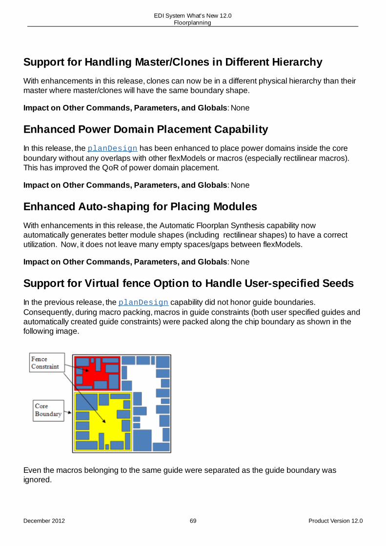
Support for Handling Master/Clones in Different HierarchyWith enhancements in this release, clones can now be in a different physical hierarchy than theirmaster where master/clones will have the same boundary shape.
Impact on Other Commands, Parameters, and Globals: None
Enhanced Power Domain Placement CapabilityIn this release, the planDesign has been enhanced to place power domains inside the coreboundary without any overlaps with other flexModels or macros (especially rectilinear macros).This has improved the QoR of power domain placement.
Impact on Other Commands, Parameters, and Globals: None
Enhanced Auto-shaping for Placing ModulesWith enhancements in this release, the Automatic Floorplan Synthesis capability now automatically generates better module shapes (including rectilinear shapes) to have a correctutilization. Now, it does not leave many empty spaces/gaps between flexModels.
Impact on Other Commands, Parameters, and Globals: None
Support for Virtual fence Option to Handle User-specified SeedsIn the previous release, the planDesign capability did not honor guide boundaries.Consequently, during macro packing, macros in guide constraints (both user specified guides andautomatically created guide constraints) were packed along the chip boundary as shown in thefollowing image.
Even the macros belonging to the same guide were separated as the guide boundary wasignored.
December 2012 69 Product Version 12.0
EDI System What's New 12.0Floorplanning
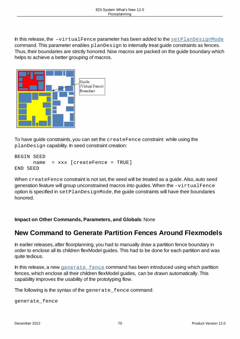
In this release, the –virtualFence parameter has been added to the setPlanDesignModecommand. This parameter enables planDesign to internally treat guide constraints as fences.Thus, their boundaries are strictly honored. Now macros are packed on the guide boundary whichhelps to achieve a better grouping of macros.
To have guide constraints, you can set the createFence constraint while using theplanDesign capability. In seed constraint creation:
BEGIN SEED name = xxx [createFence = TRUE]END SEED
When createFence constraint is not set, the seed will be treated as a guide. Also, auto seedgeneration feature will group unconstrained macros into guides. When the –virtualFenceoption is specified in setPlanDesignMode, the guide constraints will have their boundarieshonored.
Impact on Other Commands, Parameters, and Globals: None
New Command to Generate Partition Fences Around FlexmodelsIn earlier releases, after floorplanning, you had to manually draw a partition fence boundary inorder to enclose all its children flexModel guides. This had to be done for each partition and wasquite tedious.
In this release, a new generate_fence command has been introduced using which partitionfences, which enclose all their children flexModel guides, can be drawn automatically. Thiscapability improves the usability of the prototyping flow.
The following is the syntax of the generate_fence command:
generate_fence
December 2012 70 Product Version 12.0
EDI System What's New 12.0Floorplanning

[-help][-min_gap float][-target_util float][ [-hInst {hInst(s)}] | [-module {module(s)}] | [-inst_group{instGroup(s)}] ]
Impact on Other Commands, Parameters, and Globals: None
Support for Bus Guides in Relative FloorplanIn this release, bus guide support has been added to the relative floorplan capability. Thisenhancement avoids having to re-design bus guides after small floorplan refinements, like, littlemovements of macros and partitions or stretches of partitions. Now, when the master object ismoved, the bus guide segments which had been constrained will be moved and will maintainconnectivity.
You can now use the autoGenRelativeFPlan -busGuide command to generate bus guidesegments connection.
Also, use the relativeFPlan command to generate a constraint, bind one bus guidesegment to one reference object. The following parameters have been added to therelativeFPlan command:
relativeFPlan [--masterSlave {-masterType masterType -masterName masterName -slaveType slaveType -slaveName slaveName}]
Impact on Other Commands, Parameters, and Globals: None
Blackblob Capability made ObsoleteIn this release the Blackblob capability has been made obsolete. The flexModel is a super set ofblackblob capabilities. With the support of flexModels, it removes the need for using blackblobs.The flexModels should be used for prototyping instead.
Impact on Other Commands, Parameters, and Globals:
The following commands have been removed from the software:
elaborateBlackBlobloadBlackBlobNetlist
December 2012 71 Product Version 12.0
EDI System What's New 12.0Floorplanning

loadBlackBlobNetlistspecifyBlackBlobunplaceBlackBlobunspecifyBlackBlob
December 2012 72 Product Version 12.0
EDI System What's New 12.0Floorplanning

13
Structured Data PathRelease 12.0 Enhancements
readSdpFile Command Enhanced To Support More Than 10 skipSpace VariablesSupport Added for Reusing SDP InstantiationsNew Buttons in the SDP Browser
Release 12.0 Enhancements
readSdpFile Command Enhanced To Support More Than 10skipSpace VariablesThe readSdpFile command reads in a relative placement file (in .sdp format) and then calls placeSdpGroup to place all the structured data path (SDP) elements defined in the file. In previousreleases, you could specify only up to 10 variables for skipSpace in the .sdp file. In this release,this restriction has been removed so that you can define as many skipSpace variables asrequired.
Support Added for Reusing SDP InstantiationsIn traditional structured data path design, a low-level data path corresponding to a hierarchicalmodule in a netlist may need to be reused many times in other data paths. With the SDP syntaxsupported in previous releases, you had to re-specify this low-level data path each time it had tobe instantiated in other data paths. This made the SDP file bigger and difficult to use.
To improve usability, the SDP file format in this release has been enhanced to support reusecapability. The data path macro definition can be specified with the new define keyword. Oncespecified, this macro definition can be instantiated or and then used multiple times in a data pathspecification by using the use keyword.
The SDP reader has been enhanced to handle the new SDP syntax, including nested macrodefinitions. The SDP reader can also handle SDP macro definitions that are in a separate SDP filethan the data path that references them.
New Buttons in the SDP BrowserThe following buttons have been added to the SDP Browser to make it easier to use:
clear : Use the clear button to clear any existing text string in the Find text input field.Top : Use the new Top button in the SDP Browser to return to the top of the structured
December 2012 73 Product Version 12.0
EDI System What's New 12.0Structured Data Path

data path quickly. In previous releases, you had to click the Previous button several timesor restart the browser to return to the top view of the SDP browser.
December 2012 74 Product Version 12.0
EDI System What's New 12.0Structured Data Path
14
Multiple Supply Voltage (MSV)Release 12.0 Enhancements
New Options for optPowerSwitchNew Options for reportPowerDomainNew Option for replacePowerSwitch
Release 12.0 Enhancements
New Options for optPowerSwitchThe command optPowerSwitch has the following new variables:
-setDontUseCells that prevents the specified library cells from being used duringpower switch ECO function. -idsatmargin that scales the power switch instance current according to the marginvalue specified. This scaled power switch instance current value is then used forcomputation in resize mode operation.-reportOnly that reports the power switch instance currents, the downsize and upsizeinformation to the file fileName.rpt without performing any power switch optimization.-area enables power switch ECO to optimize the power switch instances within areadefined by this parameter.
New Options for reportPowerDomainThe command reportPowerDoman has the following new variables:
-pin: Lists the pins and the option is of type string Pin1, Pin2 .... This option isoptional.-verbose: Prints out the detail information and is optional.
New Option for replacePowerSwitchThe command replacePowerSwitch has a new variable -xyRangeFromCenterInst thatselects the power switch instances whose lower left corner is in the range from lower left corner ofthe specified instance (-insts) for replacement with switch cell (-cell).
December 2012 75 Product Version 12.0
EDI System What's New 12.0Multiple Supply Voltage (MSV)
15
NanoRoute Router
Release 12.0 EnhancementsNanoRoute Support for LEF Properties EnhancedgetNanoRouteMode and setNanoRouteMode Commands ModifiedEnhanced Violation Marker Support
Release 12.0 Enhancements
NanoRoute Support for LEF Properties EnhancedIn this release, the NanoRoute router has been enhanced to support PARALLEL for cut to metalCONCAVECORNER LEF property.
For more information, see the “LEF Syntax” chapter of the LEF/DEF Reference.
Impact on Other Commands, Parameters, and Globals: None
getNanoRouteMode and setNanoRouteMode Commands ModifiedIn this release, the following parameters of the getNanoRouteMode and setNanoRouteMode commands have been made obsolete:
-dbCheckRule
-dbReportWireExtraction
-dbReportWireExtractionEcoOnly
-drouteAutoCreateShield
-drouteCheckMinstepOnTopLevelPin
-drouteElapsedTimeLimit
-routeAutoGgrid
-routeDeleteAntennaReroute
-routeInsertAntennaInVerticalRow
-routeMergeSpecialWire
-routeSiEffort
-routeTdrEffort
-routeUseBlockageForAutoGgrid
December 2012 76 Product Version 12.0
EDI System What's New 12.0NanoRoute Router

-routeWithSiPostRouteFix
-timingEngine
Note: The obsolete command parameters have been removed in this release and have not beenreplaced. Update your scripts to avoid warnings and to ensure compatibility with future releases.
Impact on Other Commands, Parameters, and Globals: None
Enhanced Violation Marker SupportIn the previous release, the violation markers only indicated the location of the violation. They didnot guide you to the nature of the violation. With enhancements in this release, the marking boxprovides full information about the violation including error type, layer name, net object, location,and a description in the violation browser.
The Nanoroute DRC markers are edge based markers which are in design view and ViolationBrowser.
Impact on Other Commands, Parameters, and Globals: None
December 2012 77 Product Version 12.0
EDI System What's New 12.0NanoRoute Router
16
TrialRoute Router
Release 12.0 EnhancementsTrialRoute Support for get_metric APIs
Release 12.0 Enhancements
TrialRoute Support for get_metric APIsThe trialRoute now supports get_metric APIs and enables you to query existing routingmetrics at command line.To enable this capability, routeDesign just calls the 'get_metrics' API after generating therouting metrics.
For more information, see the Design Metrics chapter of the EDI System Text CommandReference .
Impact on Other Commands, Parameters, and Globals: None
December 2012 78 Product Version 12.0
EDI System What's New 12.0TrialRoute Router

17
Timing BudgetingRelease 12.0 Enhancements
Power Pin Support in Budgeted Timing Models for Low Power DesignsJustify Budget Enhanced
Release 12.0 Enhancements
Power Pin Support in Budgeted Timing Models for Low PowerDesignsIn a variation of the CPF-based flow, the CPF file contains only power domain information andassigns timing libraries to them. Since voltages are not defined in the CPF file, the voltageinformation comes from these timing libraries through constructs like voltage_map, pg_pin,related_power_pin and related_ground_pin. Previously, these constructs were notsupported in the timing models generated by budgeting. It is important to have this voltageinformation in budgeted timing models to ensure that the top-level flow is able to use the budgeted.lib containing the power and ground pin information for an accurate CPF-based flow.
Timing Budgeting has been enhanced to support PG pins in budgeting timing models. Therefore, ifa full-chip design has libraries defined with PG pins, timing libraries generated for eachinstance/block will have voltage information. To support this enhancement, the budgeting timinglibrary now imports the following constructs from the full-chip library:
Voltage Maps - are written for all the voltages that are coming inside a partition/instancefor which the timing model is being written.
voltage_map( vdd, 0.903 );
This information is at the library level. Every voltage has a name given and a value isassociated with it.
Cell Level PG Pin Information - For each voltage map, a related pg pin is defined for thecell. It will have a pin name and the voltage name it is to be connected to.
pg_pin ( vdd ) { voltage_name : vdd; pg_type : primary_power; direction : input; physical_connection : device_layer; }
December 2012 79 Product Version 12.0
EDI System What's New 12.0Timing Budgeting
This information is at the cell level. The pins described in this definition are global in the libraryscope. All the pins in the library are considered to be connected to one of these pins.
Pin Level PG Information - At each port of the partition/instance, there will be a relatedpg_pin construct that specifies from which power/ground pin is the port being driven.
pin (q) { related_power_pin : vdd; related_ground_pin : vss; .....
Justify Budget EnhancedIn earlier releases, when you changed the budgets on a port using the modifyBudgetcommand, the justify budget report would still show the original budget instead of the modifiedbudget. The justify budget report has now been enhanced to display the modified budget and thejustification for that (user applied or derived from user applied), thereby ensuring accuracy.
For manual budgeting, the budget of the port can change in the following scenarios:
When you directly apply a constraint on the port, the justify report shows the location of thefile from which the constraint has been taken, the applied constraint, and the port on whichit was applied.
Partition: blockPort: sub_inBudgeted constraint type: set_input_delay(setup rise)Virtual Clock: clk1_setupholdBudget Applied by modify budget statement (/../../modify.tcl:3) : set_input_delay 1.9 -clock [get_clocks {clk1_setuphold}] -max -rise [get_ports {sub_in}] -add_delayApplied constraint = 1.900Start clock: clk1 clock edge: riseEnd clock: clk1 clock edge: rise
When you apply a constraint on a connected port, the budget of that port also changes.The output port will be impacted due to modification at the input port as it is one continuouspath. Budgets are modified at the output port by adjusting the required time of the port withthe extra delta delay given to (or taken away from) the connected port. Therefore, themodifications at the input port is reflected in the justify report for both the input port and theoutput port, wherein, the budgets are being recalculated for the output port based on themodification.The justify report has information about the port, the delta and how that delta affected theconstraint value at the given port.
Budget Impacted by modify budget statement (location of the file in which theapplied constraint is specified) :
December 2012 80 Product Version 12.0
EDI System What's New 12.0Timing Budgeting

set_input_delay 1.9 -clock [get_clocks {clk1_setuphold}] -max -rise [get_ports {sub_in}] -add_delayImpact of modify budget(modDelta) = 0.911Available budget after adjustment(AvailTime)=(10.000 - 2.982) - (0.911) = 6.107
December 2012 81 Product Version 12.0
EDI System What's New 12.0Timing Budgeting

18
RC ExtractionRelease 12.0 Enhancements
RCDB Reading Enhanced to Fix ErrorsNew Command for Providing Information about the Contents of the RCDBObsolete Command Parameters - Removed from the SoftwareTQRC/IQRC Enhanced to Complete Broken RC NetworksTQRC/IQRC Enhanced to Perform Incremental Extraction After defIn and Metal FillCommandsAccuracy of PreRoute Extraction Enhanced for Signal NetsReduction in Peak Memory Consumption by spefIn in Sequential Mode
Release 12.0 Enhancements
RCDB Reading Enhanced to Fix ErrorsEarlier, the RCDB flow was disrupted if there was any inconsistency between the design netlistand the RCDB. For example, if the design was modified before loading the corresponding RCDB,the software gave an error message.
This behavior is unlike that of the SPEF file-based flows that continue even if there is adesign/RCDB mismatch. In this release, the EDI System is enhanced so that the QRC-RCDB flowalso continues to run in such situations. For this, the command, read_parasitics, isenhanced to do error checking and fixing during RCDB reading. This command fixes the datawhen a single flat RCDB is read by using the -force parameter of this command.
Impact on Other Commands, Parameters, and Globals:None
New Command for Providing Information about the Contents ofthe RCDBIn this release, the EDI System is enhanced to provide you a mechanism to check the basiccontents of the RCDB being read so that they can debug the issues related to RCDB reading, ifrequired. For this, a new command, report_rcdb is provided that displays the contents of theRCDB being read. This command can be used to report all the information about the RCDBcontents such as the RCDB version, the OS bit (64bit/32bit), whether the RCDB contains nodelocations or not, coupled or decoupled data, statistical data, number of corners, RCDB source(QRC or Encounter), and so on.
December 2012 82 Product Version 12.0
EDI System What's New 12.0RC Extraction

The command has the following syntax:
report_rcdb-help<rcdb_dir_name>
Impact on Other Commands, Parameters, and Globals:None
Obsolete Command Parameters - Removed from the SoftwareThe following command parameters have been removed from the software:
setExtractRCMode -ipdb <dirname>
This parameter used the interconnect parasitic database (ipdb), which allowed faster directaccess instead of the RCDB. This feature is now ON by default. setExtractRCMode
-noReduce {true | false}
This parameter was used to specify that the software should NOT perform RC reduction. Itis no longer required because the software does not perform RC reduction by default. setExtractRCMode
-rcdb {filename}
This parameter was used to specify the RCDB output filename. It is no longer requiredbecause the software generates the RCDB in the current working directory by defaultunless you have specified an alternative location, using either the FE_TMPDIR or theTMPDIR variable. setExtractRCMode
-scOpTemp
This parameter was used to specify the derating value to be used in single-corner analysismode. This parameter is obsolete because it is not supported in the MMMC mode. Usethe -T parameter of the MMMC commands, create_rc_corner and update_rc_corner instead.setExtractRCMode
-useNDRForClockNets {true | false}
This parameter was used to specify the non-default rules from LEF to calculate theapproximate shielding and spacing values, instead of using the density values. This featureis ON by default. spefIn
-dumpMissedNet mnFileName
This parameter was used to provide a detailed listing of all the missing nets to thefile, mnFileName . It is no longer required because the software prints the missing nets in
December 2012 83 Product Version 12.0
EDI System What's New 12.0RC Extraction

the file, rc_corner_name.missing_nets.rpt by default.
Impact on Other Commands, Parameters, and Globals: None
TQRC/IQRC Enhanced to Complete Broken RC NetworksEarlier, if the routing of a net was incomplete or broken, TQRC/IQRC skipped the extraction forthese nets. On analysis, it was found that this resulted in slowing down the delay calculation.
In this release, TQRC/IQRC is enhanced to complete the RC networks of broken nets by addinglow value resistors. The timing value for such nets may not be as accurate as that for other netsbut it is better than when the extraction of broken nets was skipped entirely.
TQRC/IQRC Enhanced to Perform Incremental Extraction AfterdefIn and Metal Fill CommandsFor 65nm and lower geometry nodes, TQRC and IQRC extraction engines are recommended forpostRoute flow and ECO steps, respectively. These extraction engines have better correlation withsignoff extraction engines such as QRC. However, along with better accuracy these extractionengines also have a higher runtime when compared to detail extraction.
Although this runtime can be reduced by using the multiCPU mode, a much larger runtimeimprovement comes from performing incremental extraction where extraction is either skipped orperformed on fewer nets depending on the design/route changes in flow runs.
Currently, incremental extraction capability of TQRC/IQRC is not available after running defIn andmetal fill commands. Therefore, TQRC/IQRC is forced to perform fullchip extraction after runningdefIn and metal fill commands.
In this release, TQRC/IQRC incremental extraction support is extended to all types of gray datachanges (defIn) and metal fill changes. The performance, accuracy, and memory will remain thesame as that of the rest of the commands currently supported by incremental extraction.
Accuracy of PreRoute Extraction Enhanced for Signal NetsEarlier, a significant scale factor variation was seen both across different corners of the samedesign and across the same corner of different designs, especially for lower nodes. It was alsoseen that even a minor netlist change resulted in a large variations in scale factors in some cases.
In this release, the accuracy of preRoute extraction for signal nets is enhanced so that these largescale factor variations are controlled and remain close to the signoff extraction results formost designs.
Reduction in Peak Memory Consumption by spefIn in Sequential
December 2012 84 Product Version 12.0
EDI System What's New 12.0RC Extraction

ModeEarlier, the peak memory consumption during sequential spefIn was almost double thatconsumed during multiple-CPU spefIn .
In this release, the software is enhanced so that the peak memory consumption duringsequential s pefIn is as low as that during multiple-CPU spefIn .
December 2012 85 Product Version 12.0
EDI System What's New 12.0RC Extraction

19
Timing
Release 12.0 EnhancementsConstraint Handling Enhancements
Ability to Override Local Clock Latency ValueReporting Enhancements
Added New Global Variable to Track Reported Paths LimitAbility to Report on AOCV Stage CountsTiming Report Enhanced to Show Markers for PinsAdded New Command to Report AOCV Derating FactorsAdded New Parameters for Statistical DeratingAbility to Perform Arc-Based AOCV Weight AnalysisAdded New Global to Improve Reporting of Clock ObjectsAdded New Property AttributeAdded New Property to Report ConstantsAdded New Library PropertiesReport_timing Command Enhanced
Timing ModelingAbility to Perform AOCV-Based ETM Extractiondo_extract_model Command Enhancements
Other EnhancementsAbility to Perform AOCV Analysis on Data PathsAdded New Property to Report MacrosAdded New Global to Control Clock Reconvergence
Release 12.0 Enhancements
Constraint Handling Enhancements
Ability to Override Local Clock Latency Value
The set_clock_latency -clock_gate parameter has been added to allow setting the local clocklatency value on pin or port objects. This setting overwrites the existing latency value of clockgating cells and is used when performing timing checks against the specified pins or ports.
Reporting Enhancements
Added New Global Variable to Track Reported Paths Limit
December 2012 86 Product Version 12.0
EDI System What's New 12.0Timing

You can use the timing_report_enable_max_path_limit_crossed variable to determine if thenumber of reported paths for a particular clock group equals the specified maximum paths limit.When this global is set to true, the software will issue a warning message in case the number ofreported paths for a clock group is equal to the given maximum paths limit. This applies to bothgraph- and path-based reporting modes.
Impact on Other Commands, Parameters, and Globals: This variable is supported in clockgroup-based non-statistical reporting flows only. The clock group-based reporting mode can beenabled by setting timing_path_groups_for_clocks variable to true.
Ability to Report on AOCV Stage Counts
You can query on graph-based AOCV stage counts for timing arcs. The following new propertieshave been added to get_property and report_property commands:
Data Path:
aocv_stage_count_data_early: Returns AOCV stage count values for a timing arcon an early data path.aocv_stage_count_date_late: Returns AOCV stage count values for a timing arcon a late data path.
Launch Clock Path:
aocv_stage_count_launch_clock_early: Returns AOCV stage count values inAOCV mode for a given timing arc that is a part of early launch clock paths.aocv_stage_count_launch_clock_late: Returns AOCV stage count values inAOCV mode for a given timing arc that is a part of late launch clock paths.
Capture Clock Path:
aocv_stage_count_capture_clock_early: Returns graph based AOCV stagecount values in AOCV mode for a given timing arc that is a part of early capture clockpaths.aocv_stage_count_capture_clock_late: Returns graph based AOCV stagecount values in AOCV mode for a given timing arc that is a part of late capture clock paths.
You can specify report_timing -format stage_count option to view “Aocv Stage Count”column in the report output.
Impact on Other Commands, Parameters, and Globals: This enhancement impacts the followingproperty query commands:
get_property [get_arcs –from * -to *] propertyName
list_property –type timing_arc
report_property [get_arcs –from * -to *]
December 2012 87 Product Version 12.0
EDI System What's New 12.0Timing
Timing Report Enhanced to Show Markers for Pins
The report_timing command output has been enhanced to display markers that identify the pinsspecified using the –from, -to, or -through parameters. This feature provides betterreadability. The markers, displayed as ‘->’, show up in the ‘timing point’ or ‘ hpin’ column (if the‘timing point’ column is not available) of the timing report.
To enable this feature, you can set the timing_report_enable_markers global variable to true. Bydefault, this global is set to false.
Impact on Other Commands, Parameters, and Globals: None
Added New Command to Report AOCV Derating Factors
The following command has been added to report AOCV derate factors in path based AOCVanalysis mode:
report_pba_aocv_derate
The report contains details of all the cells and the worst derating applied on each cell for all thereported paths. This command is supported in AOCV mode only.
Impact on Other Commands, Parameters, and Globals: Using this command might result inincreased runtime.
Added New Parameters for Statistical Derating
The following parameters have been added to the set_timing_derate command to allow deratingfactors for statistical data:
-corner: Applies derating on cells or nets that are modeled as corner data elements. Thespecified derating factor is applied to both the mean and sensitivities of the delays (cornerobjects can have propagated sensitivities).
A cell with no timing arc data in a library that has any sensitivity information with respect to anyparameter defined in SPDF are considered as a corner object. All cells that do not qualify thisare considered to be statistical objects.A net with parasitic data that has no sensitivity information with respect to any parameterdefined in SPDF is considered as a corner object. All nets that do not qualify this areconsidered to be statistical objects.
-statistical: Applies derating on cells or nets that are modeled as statistical dataelements. The specified derating factor is applied to both the mean and sigma of delays.
If both set_timing_derate –corner and –statistical options are not specified,the derating factor is equally applied on variation and corner objects. This is equivalent toissuing two separate set_timing_derate commands, one with –statistical optionand another with –corner option.
December 2012 88 Product Version 12.0
EDI System What's New 12.0Timing

Ability to Perform Arc-Based AOCV Weight Analysis
The following enhancements have been made:
The define_property/set_property command allows you to perform arc-based AOCVweight analysis. You can use the following library property:
aocv_weight
For example,
define_property -type float -object_type lib_arc aocv_weightset_property [get_lib_arcs -of_objects slow/INVX1] aocv_weight 8
The software uses this property during analysis for computing the stage count.
To display AOCV weight values in the timing report, you can specify report_timing –format aocv_weight option. This enables reporting of column named “Aocv Weight” inthe timing report, which shows the respective AOCV weights on path elements.You canalso use the get_property command to return AOCV weight values.
Added New Global to Improve Reporting of Clock Objects
Earlier, the software identified some of the pins as clock network pins instead of data pins. Thisfollowing new global variable has been added to improve reporting of pins:
timing_property_clock_used_as_data_unconstrained_clock_source_paths
: When set to true, the is_clock_used_as_data timing property returns trueirrespective of whether the clock source path is constrained or unconstrained.
Impact on Other Commands, Parameters, and Globals: None
Added New Property Attribute
The get_property command now supports the timing_model_type property for cells andinstances. This property indicates the model type for a given cell or instance. The supportedvalues are abstracted, extracted, and qtm.
Added New Property to Report Constants
The get_property/report_property command has been enhanced to report constants on pins orports. The following new property has been added:
user_constant_value: Returns constant values from netlists or constraints.
Added New Library Properties
The get_property/report_property commands support the following library attributes:
December 2012 89 Product Version 12.0
EDI System What's New 12.0Timing

slew_lower_threshold_pct_fall: Returns the value of lower threshold point usedin modeling the delay of a pin falling from 1 to 0.slew_upper_threshold_pct_fall: Returns the value of upper threshold point usedto model the delay of a pin falling from 1 to 0.slew_lower_threshold_pct_rise: Returns the value of lower threshold point usedto model the delay of a pin rising from 0 to 1.slew_upper_threshold_pct_rise: Returns the value of upper threshold point usedto model the delay of a pin rising from 0 to 1.slew_derate_from_library: Specifies how the transition times found in the libraryneed to be derated to match the transition times between the characterization trip points.input_threshold_pct_fall: Returns the value of threshold point on an input pinsignal falling from 1 to 0, which is used in modeling the delay of a signal transmitting froman input pin to an output pin.input_threshold_pct_rise: Returns the value of threshold point on an input pinsignal rising from 0 to 1, which is used in modeling the delay of a signal transmitting from aninput pin to an output pin.output_threshold_pct_fall: Returns the value of threshold point on an outputsignal falling from 1 to 0, which is used in modeling the delay of a signal transmitting froman input pin to an output pin.output_threshold_pct_rise: Returns the value of threshold point on an outputsignal rising from 0 to 1, which is used in the modeling of a signal transmitting from an inputpin to an output pin.
Report_timing Command Enhanced
Earlier, the report_timing command reported all the paths for clocks generated on specified pins orports. Now, the command filters out wrong paths, and displays only the valid paths.
For example, if a generated clock apll1/CLKI is created on pin apll1/CLKI, then thefollowing command will only display the valid paths:
report_timing -clock_from apll1/CLKI -to [ get_pins apll1/CLKI]
Timing Modeling
Ability to Perform AOCV-Based ETM Extraction
The following global variable has been added to allow specification of AOCV derating mode:
timing_extract_model_aocv_mode
The valid values are:
graph_based: Specifies that the delays in the timing model are derated using the
December 2012 90 Product Version 12.0
EDI System What's New 12.0Timing

graph-based stage counts.path_based: Specifies that the delays in the timing model are derated using thetotal path stage count of worst path between those pin pairs.none: Specifies that the delays in the timing model are underated base delays.
By default, this variable is set to none.
do_extract_model Command Enhancements
The following new parameter has been added to the do_extract_model command:
–pg: Allows power or ground related pin information to be extracted inside the extractedmodel.
Other Enhancements
Ability to Perform AOCV Analysis on Data Paths
The timing_aocv_analysis_mode global variable has been enhanced to support thecapability of counting the number of stages of launch/capture clock and data paths separately inthe AOCV flow. The following new option has been added to support this feature:
separate_data_clock: Calculates the AOCV stage count for clock paths and datapaths separately. Both clock and data paths have related AOCV derating factors.
Added New Property to Report Macros
You can use the following new get_property/report_property option to query on timinglibrary cells:
is_interface_timing: Returns a value of true if a library cell has interface timingspecified for that cell.
Added New Global to Control Clock Reconvergence
The following new global allows you to specify the branch point to use for computing clock pathpessimism removal (CPPR) adjustment when there is reconvergence in the clock tree:
timing_cppr_skip_clock_reconvergence
When set to false, the software uses the branch point closest to the register clock pins wherethe clocks reconverge. When set to true, the software uses the farthest branch point from theregister clock pins (that is, the branch point closest to the clock root pin where the clocks diverge).By default, this global is set to false.
December 2012 91 Product Version 12.0
EDI System What's New 12.0Timing

20
Timing DebugNew Options for load_timing_debug_reportThe command load_timing_debug_report has the following new options:
-additonal_slack_past_wns: Reports all the paths with slack worse than WNS andthe additional specified slack value.-num_path: Specifies the number of paths to be reported in the detailed path violations.-proto: Creates flex model categories and displays the top path of the top 8 (by default)categories. This option can be used for design that has flexModels.
December 2012 92 Product Version 12.0
EDI System What's New 12.0Timing Debug

21
VerificationRelease 12.0 Enhancements
New Command To Support 20nm and Lower DRC RulesVerify Geometry Enhancements
Option -minPinArea Now ObsoleteOption -warning Now Obsolete
Violation Browser EnhancementsAuto Zoom Enhanced To Display Only Active Layers for ViolationsOption Added for Limiting Number of Errors Displayed Per TypeSupport Added for Complex Logical Expressions for Filtering ViolationsNew Forms Added for Loading and Saving DRC Markers
Release 12.0 Enhancements
New Command To Support 20nm and Lower DRC RulesEDI System now supports DRC check of 20nm and lower designs. As verifyGeometry does notsupport 20nm DRC rules, this release introduces a new command, verify_drc, for 20nm and lowerDRC rules check. Using verify_drc, you can check for DRC violations in a specified area orlayer range in a 20nm design. You can also choose to check only special wires or cells.verify_drc can also be used for 28nm and above rules. However, you need a 20nm license touse verify_drc. Therefore, you can continue to use verifyGeometry for DRC check of28nm and above designs.
Impact on Other Commands, Parameters, and Globals: If you use verifyGeometry for a20nm design, EDI System displays the following warning:
The verifyGeometry command does not support 20nm and below advanced rules. Use verify_drc instead.
Verify Geometry Enhancements
Option -minPinArea Now Obsolete
Option -minPinArea of the verifyGeometry command is now obsolete. Use the -sameCellViol option instead to report the minimum area violations for pin shapes in the cell,along with other cell violations. Although the obsolete option still works in this release, update yourscript to use -sameCellViol instead to ensure compatibility with future releases.
Impact on Other Commands, Parameters, and Globals: getVerifyGeometryMode -minPinArea and setVerifyGeometryMode -minPinArea are also now obsolete.
Option -warning Now Obsolete
From this release, option -warning of the verifyGeometry command is obsolete. Thisoption is being removed as Verify Geometry does not issue warning markers.
Impact on Other Commands, Parameters, and Globals: getVerifyGeometryMode -warning and setVerifyGeometryMode -warning are also now obsolete.
Violation Browser Enhancements
Auto Zoom Enhanced To Display Only Active Layers for Violations
The Layer field in the Violation Browser displays the layer on which each violation occurs. Whenyou select a violation in the browser, the Auto Zoom feature automatically zooms into the violationin the main window display. However, in previous releases, you then need to manually turn offdisplay of other layers so that you can focus on the layer in which the violation occurs. In thisrelease, the Auto Zoom feature in Violation Browser has been enhanced to display only the active
December 2012 93 Product Version 12.0
EDI System What's New 12.0Verification

layers related to the selected violation marker. The active layers for a violation includes the layeron which the violation occurs and the adjacent layers. This enhancment makes it easier for you toreview a violation.
Option Added for Limiting Number of Errors Displayed Per Type
When loading a large DRC file with millions of violations, the EDI System database can becomevery slow. In this release, you can use the new -max_error_per_type option of theviolationBrowser command to specify a limit for the number of violations parsed for each violationtype. The Violation Browser then parses only the specified number of violations from the DRC filefor each type of violation. For example, if you set violationBrowser -max_error_per_type 500, the Violation Browser parses only 500 markers per error type.This enhancement prevents the database from becoming very slow while loading large DRC filesand makes it easier for you to review violation markers in the browser.
You can also specify the maximum number for each error type from the GUI by using the ErrorPer Type option in the Violation Browser Settings form.
December 2012 94 Product Version 12.0
EDI System What's New 12.0Verification

By default, the Violation Browser displays all markers.
Impact on Other Commands, Parameters, and Globals: None
Support Added for Complex Logical Expressions for Filtering Violations
In previous releases, you could use only one of the AND, OR, and NOT conditions for filteringviolations. Now, you can use complex expressions with multiple logical operators to filter violations.For example, if you want to view only the violations occuring on Metal4 or Metal5 layers andwant to exclude short violations, you can use the following filter string with the new -filter_query option of the violationBrowser command:
!Short*(M4+M5)
Here:
! refers to the NOT condition.x specifies the AND condition.+ specifies the OR condition.
New Forms Added for Loading and Saving DRC Markers
You can now load and save database DRC markers directly from the Violation Browser using thehighlighted optons in the Violation Browser.
December 2012 95 Product Version 12.0
EDI System What's New 12.0Verification

Click Save to save the DRC file. This opens a form that allows you to specify the path and namefor saving the DRC file. This is equivalent to using the saveDRC command.
Click Load to load an existing database DRC file. This opens a form in which you can browse andselect the DRC file to be loaded. This is equivalent to using the loadDrc -incrementalcommand.
December 2012 96 Product Version 12.0
EDI System What's New 12.0Verification
22
Power CalculationRelease 12.0 Enhancements
read_activity_file Parameters ConsolidatedMulti-Threading Support for Dynamic Vector-Based Power Analysis FlowPower Analysis Reporting EnhancedClock-Gating Efficiency Reports ImprovedVariation in Switching Power Numbers when Running Power Analysis from EDI
Release 12.0 Enhancements
read_activity_file Parameters ConsolidatedIn this release, nine parameters of the read_activity_file have been made obsolete, andhave been consolidated into three new parameters to simplify and streamline the use model. Thefollowing table lists the obsolete parameters, and the command parameters that replace them:
Obsolete Parameters Replaced with
-scale_tcf_duration scalefactor
-scale_fsdb_duration scalefactor
-scale_vcd_duration scalefactor
-scale_duration scalefactor
-fsdb_block fsdb_block_name
-tcf_block tcf_block_name
-vcd_block vcd_block_name
-block block_name
-fsdb_scope fsdb_scope_name
-tcf_scope tcf_scope_name
-vcd_scope vcd_scope_name
-scope scope_name
The enhanced read_activity_file command provides the needed functionality for theobsolete parameters. The obsolete parameters still work in this release but a warning messagewill be displayed stating that these parameters will not be supported in a future release.
Multi-Threading Support for Dynamic Vector-Based PowerAnalysis Flow
December 2012 97 Product Version 12.0
EDI System What's New 12.0Power Calculation

The Power Analysis engine has been enhanced to support multi-threading in the dynamic vector-based flow. In the multi-threading mode, a job is divided into several threads, and multipleprocessors in a single machine process them concurrently. The multi-threaded processing modecan be specified using the following existing commands:
set_distribute_host –local
set_multi_cpu_usage -localCpu 4
These commands are used to control the number of CPUs to be used on a local machine formulti-threading. Multi-threading provides better runtime for both the VCD/FSDB based dynamicvector-based flows as compared to previous releases.
Power Analysis Reporting EnhancedPreviously, the following reports were generated by Power Analysis in the working directory:
powerAnalysis.cmdlog
powerAnalysis.summary.log
powerAnalysis.log
The following enhancements have been made in this release:
powerAnalysis.cmdlog and powerAnalysis.summary.log reports have beenremoved.powerAnalysis.log file has been moved to the output directory where all the poweranalysis results are written out.improved error message logging in the log file eps.log and the verbose log fileeps.logv. The eps.log file will contain limited number of WARNING/ERROR messagesand the eps.logv file will contain detailed and meaningful information.
The enhanced log files contain detailed analysis information that can be used for debuggingpurpose.
Clock-Gating Efficiency Reports ImprovedThe Clock Gate Efficiency (CGE) and Register Gating Efficiency (RGE) reporting have beenimproved to include toggles savings for each integrated clock gate (ICG). These reports nowhighlight toggle savings due to clock gating in the design, hierarchical view of toggle savings, andregister gating opportunities.
When you generate a CGE report using the command report_power –clock_gating_efficiency –outfile cge.rpt, the following information will bedisplayed:
December 2012 98 Product Version 12.0
EDI System What's New 12.0Power Calculation
Clock-gating Efficiency Report - for each clock domain, it includes the toggle rate,number of registers, number of clock gates, average clock toggle at registers, averagetoggle savings at registers, and average toggle savings histogram. Hierarchical View of Average Toggle Savings - number of clock gates and averagetoggle savings for each hierarchical module in the design
When you generate an RGE report using the command report_power –register_gating_efficiency –outfile rge.rpt, the following information will bedisplayed:
Register-gating Efficiency Report - for each clock domain, it includes the toggle rate,number of registers, number of clock gates, average clock toggle at registers, averagetoggle savings at registers, and average toggle savings histogram. Register Gating Opportunities Report - this report is sorted based on the Q/CLK toggleratio. When a register's Q/CLK ratio is greater than .25 (25%), Q toggles every other clockcycle. However, when it is less than 25%, there is a gating opportunity to reduce power.
The –cluster_gating_efficiency parameter has been added to the report_powercommand to generate the cluster efficiency report in the RGE report. This report gives theCGE/RGE metrics for the registers at the fanout of each clock gate instance in the design.
Impact on Other Commands, Parameters, and Globals: None
Variation in Switching Power Numbers when Running PowerAnalysis from EDIIn this release, there has been a default change in pre-route extraction in EDI that results inchange in switching power numbers as compared to previous releases.
December 2012 99 Product Version 12.0
EDI System What's New 12.0Power Calculation

23
Rail AnalysisRelease 12.0 Enhancements
Simplification of Auto-Fetch DC Sources CommandsBody Bias Analysis SupportedOn-Chip Voltage Regulator Analysis SupportedSupport for Region-Based SnappingEdit Pad Location Form Enhancedview_esd_violation Enhanced to View Bumps Within a Resistor RangeAbility to Control Layer ProcessingRail Analysis Reporting ImprovedSupport for Non Zero Capacitance Filler Cells for Decap Optimization FlowSub_Via Support AddedChange in Extraction Results for Designs with Dangling ResistorsBlock Level DEF Pin Checking Capability EnhancedVia Clustering EnhancedNew Parameters to Ignore Filler and Decap Cells
Release 12.0 Enhancements
Simplification of Auto-Fetch DC Sources CommandsIn this release, seven voltage source generation commands are made obsolete, and areconsolidated into the new command create_power_pads . The create_power_padscommand has been added to simplify voltage source generation, and provide the neededfunctionality for the obsolete commands. The obsolete commands still work in this release but awarning message will be displayed stating that these commands will not be supported in a futurerelease.
The following table lists the obsolete commands, and the new command parameters that replacethe obsolete commands:
Obsolete Command Replaced With
auto_fetch_dc_sources Use one of the following three methods to fetch voltagesources into the database:
fetch all voltage sourcescreate_power_pads –net net_name –
December 2012 100 Product Version 12.0
EDI System What's New 12.0Rail Analysis
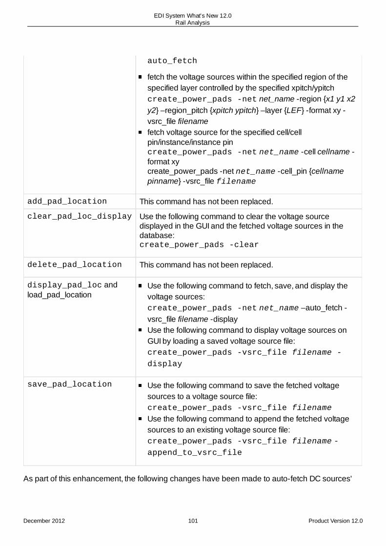
auto_fetch
fetch the voltage sources within the specified region of thespecified layer controlled by the specified xpitch/ypitchcreate_power_pads -net net_name -region {x1 y1 x2y2} –region_pitch {xpitch ypitch} –layer {LEF} -format xy -vsrc_file filenamefetch voltage source for the specified cell/cellpin/instance/instance pincreate_power_pads -net net_name -cell cellname -format xycreate_power_pads -net net_name -cell_pin {cellnamepinname} -vsrc_file filename
add_pad_location This command has not been replaced.
clear_pad_loc_display Use the following command to clear the voltage sourcedisplayed in the GUI and the fetched voltage sources in thedatabase:create_power_pads -clear
delete_pad_location This command has not been replaced.
display_pad_loc andload_pad_location
Use the following command to fetch, save, and display thevoltage sources:create_power_pads -net net_name –auto_fetch -vsrc_file filename -displayUse the following command to display voltage sources onGUI by loading a saved voltage source file:create_power_pads -vsrc_file filename -
display
save_pad_location Use the following command to save the fetched voltagesources to a voltage source file:create_power_pads -vsrc_file filename
Use the following command to append the fetched voltagesources to an existing voltage source file:create_power_pads -vsrc_file filename -append_to_vsrc_file
As part of this enhancement, the following changes have been made to auto-fetch DC sources'
December 2012 101 Product Version 12.0
EDI System What's New 12.0Rail Analysis

behavior:
Automatically fetch voltage sources on all layer shapes. Previously,the auto_fetch_dc_sources command would only fetch the voltage sources on thetop connected metal layer.Fetch multiple voltage sources for large shapes based on multiple connections. Previously,the auto_fetch_dc_sources command would only fetch one voltage source for largeshapes with multiple connections.
Body Bias Analysis SupportedEDI System has been enhanced to support body bias designs, in which body bias nets (BVDD,BVSS) are connected to body bias pins (NWELLPIN, PWELLPIN) of the cell. The main purpose ofbody bias analysis is to prevent latch-up in the circuit, reduce leakage current, and optimizeperformance. The following diagram illustrates body bias connectivity:
To support this enhancement, the following changes have been made:
Library Characterization - the body bias pins are defined by the WELL layer in the LEFmacro. The pins are connected via the tap cell (M1-CONT-DIFF/WELL) for top-level bodybias power routing. The WELL layer is mapped to the DIFF layer in the lefdef layer map,therefore, current sinks will be attached to the DIFF layer. You can use the new parameter–create_diff_layer_ports of the characterize_power_library commandto create the DIFF layer ports of body bias pins in PGV.Power Analysis -The bias pin definitions are read from the liberty (dotlibs) libraries. With
December 2012 102 Product Version 12.0
EDI System What's New 12.0Rail Analysis

body bias pin definitions in liberty, the power and ground pins with type PWELL and NWELLwill be regarded as body bias pins. You can use the new parameter –bulk_pins of theset_power_analysis_mode command when library cells have bulk pins defined inLEF but the liberty file does not contain power associated with these pins. If a liberty filedoes not have body bias definition, power analysis does not distribute power to the bodybias domain.Rail Analysis - the -process_bulk_pins_for_body_bias parameter has beenadded to the set_rail_analysis_mode command. When set to true, rail analysiswill process current sinks on the cell's bulk pin connections. This parameter is used duringbody bias analysis, where a body bias net is connected to bulk pins of the cell.
The bulk pins for a cell is defined in the cell library using theset_power_library_mode -generic_bulk_power_names -generic_bulk_ground_names command parameter. If bulk pins aredefined using set_power_library_mode -generic_power_names-generic_ground_names, then the -process_bulk_pins_for_body_bias parameter must not be used.
For more information, refer to the "Body Bias Analysis" chapter in the Encounter PowerSystem User Guide.
Impact on Other Commands, Parameters, and Globals: None
On-Chip Voltage Regulator Analysis SupportedEDI System now supports analysis of on-chip voltage regulators (Vreg) in System-on-a-chip(SoC) to stabilize voltage supplies and to handle Dynamic Voltage and Frequency Scaling (DVFS).This analysis has been included in the IR Drop analysis flow to understand how Vreg affects theon-chip voltage drop, chip package co-design, and how it interacts with the IC/package/boardsystem. This feature allows you to accurately model Vreg modules for rail analysis.
During Vreg analysis, the tool captures the noise at the output of Vreg caused due to loadingcurrent and RC effects, and uses this voltage waveform for rail analysis. In the following diagram,the chip configuration has a Vreg that is connected to an input and output domain along with acommon ground. When you perform Vreg analysis, a reduced grid is created for both input andoutput, and reduced ground resulting in a much concise RC netlist to do simulations of vectorswith these loadings. The noise at the output of Vreg is captured and used for rail analysis.
To analyze voltage regulator effects, the set_voltage_regulator_module command hasbeen introduced. For more information, refer to the "Dynamic Rail Analysis for On-Chip VoltageRegulators "section in the Dynamic Power and IRDrop Analysis chapter of the Encounter PowerSystem User Guide.
Impact on Other Commands, Parameters, and Globals: None
December 2012 103 Product Version 12.0
EDI System What's New 12.0Rail Analysis

Support for Region-Based SnappingIn this release, region-based auto fetch has been enhanced to support snapping. For region-based auto fetch, if the voltage source points that were fetched according to the start point and thespecified region pitch (xPitch/yPitch) are not on the stripe, these points will be ignored duringanalysis. Therefore, you can now use the -snap_distance parameter of thecreate_power_pads command to snap the voltage sources to a stripe within +/- snapdistance/2. If no such stripe is found, this point will not be saved into the pad location file. As aresult, the voltage sources are generated only on the stripes and these points will be saved to thepad location file.
Edit Pad Location Form EnhancedThe Edit Pad Location form has been enhanced by rearranging the form layout to improveusability.
December 2012 104 Product Version 12.0
EDI System What's New 12.0Rail Analysis

In addition, the following changes have been made:
Removed the RLC Update sectionRemoved the Fetch All Layer Shapes and Snap Constraint optionsAdded the TSV and Append to Existing File options
view_esd_violation Enhanced to View Bumps Within a Resistor
December 2012 105 Product Version 12.0
EDI System What's New 12.0Rail Analysis

RangePreviously, the view_esd_violation command reported only those bumps with effectiveresistance greater than the specified threshold value. Now, you can use the new -limitparameter to report bumps that have a resistor value in the specified range, that is, betweenvalue1 and value2. The -limit parameter must be used in conjunction with the -thresholdparameter. The -threshold parameter specifies value1 or the lower limit of the resistancevalue, and the -limit parameter specifies value2 or the upper limit of the resistance value.Resistance values must be specified in Ohm.
Impact on Other Commands, Parameters, and Globals: None
Ability to Control Layer ProcessingIn this release, the -process_layer_off parameter has been added to theview_analysis_results command to select the user-defined layers to be used forprocessing during the next analysis. This parameter allows you to turn on/off certain layers so thatyou can view specific layer-based IRdrop plots with data distribution.
view_analysis_results -process_layer_off {all | none | layer1layer2..layerN}
GUI Enhancement
The Process column has been added to the Power & Rail Results - Advanced form to control theprocessing of individual layers interactively.
Impact on Other Commands, Parameters, and Globals: None
Rail Analysis Reporting ImprovedIn this release, Rail Analysis has been improved to generate a single consolidated reportcontaining all power-grid integrity data. This report lists all power-grid integrity related problems,such as instances without voltage-source connectivity in PGDB, disconnected PGVs in PGDB,missing cells, physically disconnected cells, and so on.
Previously, the following reports were generated by Rail Analysis for each net inside the statedirectory (../state_dir/Reports):
net_name.disconnected_inst.asc
net_name .disconnected_pgv.asc
net_name .missing_pgv.asc
net_name .pwr_annotation.asc
net_name .reff_infiniti.asc
net_name .unconnected_sections.asc
December 2012 106 Product Version 12.0
EDI System What's New 12.0Rail Analysis
With the current implementation, these fragmented reports have been consolidated to generatethe net_name.pg_integrity.asc and .html files for each net in the state directory(../state_dir/<net>/Reports). The consolidated report will now also have information onweakly connected power segments, for example, stripes not connected to top level layer.
Support for Non Zero Capacitance Filler Cells for DecapOptimization FlowThe set_rail_analysis_mode -filler_cell_list command parameter now supportsnon-zero capacitance filler cells during feasibility or timing aware decap optimization. Previously,this parameter would only honor the filler cells with zero capacitance.
Sub_Via Support AddedIn this release, the software has been enhanced to apply the EM rules defined for a via object toits sub_via objects. For example, via odtap has 2 sub_vias, odtap_n and odtap_p . The EMmodel defined for odtap will be automatically applied to all the resistors belonging to odtap_nand odtap_p .
Change in Extraction Results for Designs with DanglingResistorsIn this release, the extractor embedded in Encounter Power System will remove dangling resistorson power-grid during extraction. These dangling resistors do not contribute towards any accuracyloss during rail analysis. The dangling resistors occur on shapes with open current path. However,it preserves dangling resistors for EM analysis if the process EM rules depends on currentdirection and the longest path length.
Block Level DEF Pin Checking Capability EnhancedFrom release 12.0 onwards, rail analysis considers the connectivity of the block-level power netsto the top-level DEF, if the connectivity is defined by the wildcard character (*). Previously, wildcardpin connectivity definition was not supported.
Via Clustering EnhancedRail Analysis has been enhanced to support clustering of VIA1 ports placed on follow-pin routing.Designs with follow-pin routing on M1 and M2 layers have standard cells library LEF with M1, M2,and VIA1 ports. You can now specify the set_rail_analysis_mode –cluster_via1_ports true parameter to cluster VIA1 ports for such cells in order to improveoverall extraction and rail analysis performance.
December 2012 107 Product Version 12.0
EDI System What's New 12.0Rail Analysis

In addition, the following parameter has been introduced to support layer-based custom viaclustering:
set_rail_analysis_mode –cluster_via_rule { {via_layer
number_of_equidistant_vias}… } - Controls the number of vias to cluster on alayer basis. The VIA clustering rule specified using this parameter will override the defaultclustering rule for a given accuracy mode.
The following command will cluster 100 equidistant VIA1 cuts, 200 equidistant VIA2 cuts, and 300equidistant VIA7 cuts:
set_rail_analysis_mode –cluster_via_rule { {VIA1 100}} {VIA2
200} {VIA7 300}}
The rest of the VIAs will be clustered using the default clustering rule depending upon the railanalysis accuracy mode.
New Parameters to Ignore Filler and Decap CellsIn this release, the following parameters have been added to the set_rail_analysis_modecommand to ignore filler and decap cells:
–ignore_fillers {true | false} - Ignores filler cells during power-grid viewlibrary generation or specified as fillers using the set_rail_analysis_mode –filler_cell_list command parameter. During dynamic analysis, ignore library cellsthat are tagged as FILLER cells and have no capacitance associated with the interfacenodes.Default: falseNote: Due to follow-pin routing in DEF, connectivity will not be impacted by ignoring thesecells. If a design has M1-M2 follow-pin routing, filler cells may provide additional parallelpaths for current and ignoring them may cause slight change in IRdrop results, but at amuch higher cost of performance.
–ignore_decaps {true | false} - Ignores decap cells during static analysis. It ignorescells that are tagged as DECAP cells during library characterization or set as decap cellsusing the set_rail_analysis_mode –decap_cell_list command parameter.Ignoring decaps during dynamic analysis is not recommended.Default: false
December 2012 108 Product Version 12.0
EDI System What's New 12.0Rail Analysis
24
Early Rail AnalysisRelease 12.0 Enhancements
New Parameter to Support Fast Mode ExtractionPower Gate Analysis Behavior Enhanced
Release 12.0 Enhancements
New Parameter to Support Fast Mode ExtractionIn this release, the -turbo parameter has been added to the analyze_early_railcommand to enable fast mode ERA extraction. This parameter improves extraction performanceby reducing turnaround time and memory footprint. This can result in extraction performance gainsof up to 2X, compared to the 11 release.
Note: The -turbo parameter requires the EPS-L license.
Power Gate Analysis Behavior EnhancedIn the power gate file based flow, the following enhancements were made to the power gateanalysis behavior:
The methodology to add Ron resistor to a power gate cell has been improved to minimizethe behavior difference between the power gate file flow and the power-grid view flow.The methodology to add leakage current to a power gate cell has been modified. Whenpower switch instances have the ON status, the leakage current in the power gate file isnot added for rail analysis. While in the OFF status, leakage current in the power gate file isadded. Earlier, leakage current was added for rail analysis even if power switch instanceshave the ON status.A new parameter -off_rails has been added to the analyze_early_railcommand to specify a list of switched nets in the OFF state that are to be excluded from railanalysis. Previously, it was assumed that power switch instances always have the ONstatus.Generates a report file including the Ron/Idsat/Ileakage information of power switchinstances:CELL ATERM STERM RON(Ohm) IDSAT(A) ILEAK(A)HDRSID0 TVDD VDD 12.1046 0.0368639 1.28907e-08
December 2012 109 Product Version 12.0
EDI System What's New 12.0Early Rail Analysis

December 2012 110 Product Version 12.0
EDI System What's New 12.0Early Rail Analysis
25
Mixed Signal InteroperabilityRelease 12.0 Enhancements
run_vsr GUI UpdatedsetIntegRouteConstraint Command EnhancedIntegration Constraints Editor GUI UpdatedFloating Shields Supported
Release 12.0 Enhancements
run_vsr GUI UpdatedIn this release, the run_vsr GUI (Tools Menu) supports bus constraints.
setIntegRouteConstraint Command EnhancedIn this release, setIntegRouteConstraint constraint command contains:
the new bus constraint type.the updated syntax for layerGap, shieldWidth, shieldGap, tandemWidth andgroupToOutsideSpacing
Following is the updated syntax of this command:
setIntegRouteConstraint
[-help]
-type {diffPair | matchLength | routeNet | bus}
December 2012 111 Product Version 12.0
EDI System What's New 12.0Mixed Signal Interoperability
-net {Net1 Net2}
-rule <non-default-rule-name>
[-shieldNet name |
-groupToOutsideSpacing {layer1Spacing layer2Spacing ...}]
[-layerGap {layer1 gap1 layer2[:layerN] gap2...}]
[-shieldGap {layer1 gap1 layer2[:layerN] gap2 ...}]
[-shieldWidth {layer1 width1 layer2[:layerN] width2...}]
[-tandemWidth {layer1 width1 layer2[:layerN] width2...}]
December 2012 112 Product Version 12.0
EDI System What's New 12.0Mixed Signal Interoperability
[-shieldType shieldType]
[-tandemWidth {layer1width layer2width ...}]
[-hierarchicalScope {local local_above local_below local_above_below}]
[-tolerance tolerance]
[-matchStyle style]
[-topLayer layerNumber]
[-bottomLayer layerNumber]
[-connectSupply value}]
December 2012 113 Product Version 12.0
EDI System What's New 12.0Mixed Signal Interoperability

[-layerMatch layerMatch]
Integration Constraints Editor GUI UpdatedIn this release, the Integration Constraints Editor has been updated to support bus constraintsusing the new BUS tab.
Using the new Pull Block Constraint tab, you can pull the routing constraints stored on theinterface nets of blocks in a design, to their corresponding top-level nets.
Floating Shields SupportedIn this release, the Integration Constraints Editor has been enhanced to support floating shields.The Connect Supply option now can support float as one of the value in addition to the defaultvalue anyPoint.
December 2012 114 Product Version 12.0
EDI System What's New 12.0Mixed Signal Interoperability
26
Clock Concurrent OptimizationRelease 12.0 Enhancements
setCCOptMode Command Enhanced to Set the Minimum Fanout Number for TopNets
Release 12.0 Enhancements
setCCOptMode Command Enhanced to Set the Minimum FanoutNumber for Top NetsThe -top_net_min_fanout parameter of the setCCOptMode command is used to set theminimum number of transitive fanouts in the clock tree for a net to be considered a "top" net.
All nets in a clock tree can be classified as "leaf" nets, "trunk" nets, or "top" nets. Leaf nets connectdirectly to sinks. Top nets are nets that have a transitive fanout higher than the configuredthreshold, and trunk nets are those nets that are not directly connected to sinks. Depending on thetotal number of fanouts in a tree, you may not have any top nets at all – just leaf and trunk nets.Top nets, trunk nets, and leaf nets can all use different routing rules. So if a net is determined to bea top net because its transitive fanout is greater than the threshold set by thetop_net_min_fanout parameter then it will use the top net routing rules. If it is leaf net or atrunk net then it will use leaf routing rules or trunk routing rules.
Changing the value of this parameter will change the nets that are considered as top nets.
The default value of this parameter is 0.
December 2012 115 Product Version 12.0
EDI System What's New 12.0Clock Concurrent Optimization
27
Clock Tree SynthesisRelease 12.0 Enhancements
AssumeShielding Option in the Clock Specification File is ObsoleteclockDesign Parameters not Supported with CCOpt EnginereportClockTree Command Enhanced to Write Out Information for Cell Types
Release 12.0 Enhancements
AssumeShielding Option in the Clock Specification File isObsoleteThe AssumeShielding option in the section of the clock tree specification file, which deals withattributes that clock tree synthesis (CTS) passes to NanoRoute Ultra, is now obsolete. This optionwas used to instruct CTS to assume that unshielded wires were shielded when CTS estimatedwire loading. The default value of this option was NO.
However, this option is no longer needed because of the following reasons:
1. The users can estimate the shielding effect during the preRoute stage by specifying"Shielding YES" in the specification file.
2. Specifying both options - "AssumeShielding YES" and "Shielding NO" (default) -in the spec file can lead to a conflict.
If specified, this option will be ignored by the software.
clockDesign Parameters not Supported with CCOpt EngineThe setCTSMode -engine {ck | ccopt} command is used to specify whetherclockDesign will use the EDI-CTS commands (ckSynthesis / ckECO ) or the CCOptengine to perform CTS.
When setCTSMode -engine is set to -ccopt, the EDI clock specification file is automaticallymapped to the Azuro clock specification. However, when you use the CCOpt engine, manyparameters of the clockDesign command are not supported. These parameters are onlysupported when the engine specified is ck. You can use other EDI commands and optionsinstead.
For details of commands and parameters that can be used instead of the clockDesignparameters that are not supported with the CCOpt engine, refer to the clockDesign command
December 2012 116 Product Version 12.0
EDI System What's New 12.0Clock Tree Synthesis
in the EDI System Text Command Reference document.
reportClockTree Command Enhanced to Write Out Informationfor Cell TypesThe reportClockTree command is enhanced to write out information about the cell type,instance count, and area both for leaf components (such as flip flops and latches) and non-leafcomponents (such as buffers, inverters, and clock gates) for all clocks specified in the specificationfile.Use the -area parameter of this command to write out this information.
Impact on Other Commands, Parameters, and Globals:None
December 2012 117 Product Version 12.0
EDI System What's New 12.0Clock Tree Synthesis

28
OpenAccessRelease 12.0 Enhancements
New Command to Access the 5.x Library StructureNew Parameter to Add Voltage Information to the Nets
Release 12.0 Enhancements
New Command to Access the 5.x Library StructureIn earlier releases, there was no way for the user to find out where on disk OpenAccess data isstored. In this release, you can use the new dd_get command to access the 5.x library structure.
This command has the following syntax:
dd_get
{-all_lib} |{–dd dd_objHandle | -lib libName | -cell {lib cell} | -cellview {lib cell view} }
[-children | -file | -path | -type |-name]}
Impact on Other Commands, Parameters, and Globals: None
New Parameter to Add Voltage Information to the NetsIn this release, you can use the new setOaxMode -saveNetVoltage {true | false} parameter tosave the maximum net voltage across all loaded timing views to every net. This is useful forVirtuoso to understand the maximum net voltage without looking at a CPF, or .lib files.
Impact on Other Commands, Parameters, and Globals: None
December 2012 118 Product Version 12.0
EDI System What's New 12.0OpenAccess

29
TSVRelease 12.0 Enhancements
Embedded Bump Flow Supported in Hierarchical DesignsNew Parameter Added to Output Selected Bumps
Release 12.0 Enhancements
Embedded Bump Flow Supported in Hierarchical DesignsEDI System has been enhanced to support embedded bumps in the hierarchical flow for 3D ICdesigns. At the block level, all the bumps in the LEF file were previously output as PIN which issame as normal pins. Therefore, it was difficult to distinguish bumps from normal pins. With thecurrent implementation, the tool can identify the PIN as a normal bump, which is defined as anembedded bump in the top-level.
The block-level LEF file with the embedded bump information is passed to the top-level design,and the embedded bumps are treated as normal bumps in the top-level design. The embeddedbump information can also be exchanged between adjacent dies. As a result, a chip of the currentdesign could create and assign bumps according to embedded bumps in the adjacent die.
All the 3D IC commands have been enhanced to support embedded bumps, therefore, the outputfiles generated by these commands for the downstream tools also support embedded bumps.
New Parameter Added to Output Selected BumpsIn this release, the -selected parameter has been added to the writeBumpLocationcommand to output information related to selected bumps to the bump file. With the currentimplementation, you can select the required bumps in the GUI, and specify thewriteBumpLocation -selected command to output the bump information. You can usethis parameter when you want to output bump information that is related to a specific block inhierarchical designs.
Impact on Other Commands, Parameters, and Globals: None
December 2012 119 Product Version 12.0
EDI System What's New 12.0TSV

30
Timing OptimizationRelease 12.0 Enhancements
New Command IntroducedtimeDesign Command UpdatedreclaimArea Command UpdatedsetOptMode Command Updated
New Parameters AddedGigaOpt as the Default Optimization Engine
Obsolete Parameters
Release 12.0 Enhancements
New Command IntroducedIn this release, you can use the reportLengthViolation command to run timing analysis and reportnets that exceed the maximum length constraint set by the setOptMode –maxLength parameter.
Impact on Other Commands, Parameters, and Globals: None
timeDesign Command UpdatedIn this release, the timeDesign -signOff command uses AAE as the default engine.
Impact on Other Commands, Parameters, and Globals: None
reclaimArea Command UpdatedIn this release, you can use the new reclaimArea -maintainHold parameter to run the hold-awarearea reclaim while running with AAE engine.
Impact on Other Commands, Parameters, and Globals: None
setOptMode Command Updated
New Parameters Added
In this release, the following new parameters have been added to the setOptMode command:
December 2012 120 Product Version 12.0
EDI System What's New 12.0Timing Optimization
-timeDesignNumPaths number
Allows you to select the number of paths that should be reported per path group duringtimeDesign or optDesign final summary reports.
Default : 50
-timeDesignExpandedView {true | false}
When set to true, it will force timeDesign or optDesign to print summary timing reportsas per the view in the log file.
Default : false
-timeDesignReportNet {true | false}
When set to true, this will force timeDesign or optDesign to print timing reports with thenet section.
Default : false
-postRouteAreaReclaim {none | setupAware | holdAndSetupAware}This parameter can be used after routing to reclaim area during optDesign -postRoute. Itsafely reclaims area while not impacting the timing and DRV violations.
Impact on Other Commands, Parameters, and Globals: None
GigaOpt as the Default Optimization EngineIn this release, GigaOpt is the new default optimization engine for post-route optimization. Thisnew engine is multi-threaded, scalable and deterministic so it is recommended to usesetMultiCpuUsage where possible to reduce TAT.
Using this engine, you need not run optDesign –si but rest of the use model is unchanged. Thereason for this is that GigaOpt post-route optimization will by default fix both the base timing and SItiming at the same time.
Obsolete Parameters
In this release, the following parameters of setOptMode command are obsolete.
-congOpt {true | false}
-considerNonActivePathGroup {true | false}
-critPathCellYield {true | false}
-postRouteAllowOverlap {true | false}
-yieldEffort {none | low | high}
December 2012 121 Product Version 12.0
EDI System What's New 12.0Timing Optimization

31
PlacementRelease 12 Enhancements
New Commands New Options for setPlaceModeNew Option for addFillerGap
Release 12 Enhancements
New Commands The new commands added to EDI System are:
place_connected: Places the specified standard cells close to the specified attractor withlegal location. The attractor can be IOs or hard macros. The recommended flow is to runthis command before placeDesign.
get_well_tap_mode: Returns the information about set_well_tap_mode parameters in theEDI System log file and in the EDI System console.
set_well_tap_mode: Controls the behavior of addWellTap command. The mode setting ispersistent and saved along with the database by the saveDesign command.
New Options for setPlaceModeThe command setPlaceMode has a new option -fillerGapRadius that specifies thesearching radius when solving the minimum filler gap.
The command setprerouteAsObs has been replaced with the option -prerouteAsObs.The option's function remains the same, it returns the routing layers.
A new option congRepairEffort is added which controls the effort level ofcongRepair iterations. The high effort mode is recommended for highly congested designsbecause itruns additional congRepair iterations at cost of extra runtime. The same option has alsobeen added to getPlaceMode.
New Option for addFillerGapThe command addFillerGap has a new option -radius which specifies the searching radius
December 2012 122 Product Version 12.0
EDI System What's New 12.0Placement

when solving the minimum filler gap.
December 2012 123 Product Version 12.0
EDI System What's New 12.0Placement

32
Yield AnalysisRelease 12.0 Enhancements
Yield Analysis Discontinued
Release 12.0 Enhancements
Yield Analysis DiscontinuedYield analysis is being discontinued from this release. The following yield analysis commands andstandalone executables are now obsolete:
loadYieldTechFile
reportYield
tsmc2yld
umc2yld
The associated GUI forms and documentation have also been discontinued from this release.
December 2012 124 Product Version 12.0
EDI System What's New 12.0Yield Analysis

33
Delay CalculationRelease 12.0 Enhancements
Vectorized Delay Calculation Support in MMMC with AAE
Release 12.0 Enhancements
Vectorized Delay Calculation Support in MMMC with AAEIn this release, the EDI System 12 is enhanced to support vectorized delay calculation when thesoftware is in the MMMC mode and the delay calculation engine used is the Advanced AnalysisEngine (AAE). With this enhancement the user can specify options for combining delay calculationruns for early and late simulations into a single simulation. The enhancement provides the usercontrol for improving the runtime of AAE for all analysis types. Use the combine_mmmc {none| early_late} parameter of the setDelayCalMode command to specify the combination ofyour choice for the delay calculation runs.
When none is specified, the software does not combine any delay calculation runs. Whenearly_late is selected, the software combines early and late simulations of a single corner intoone delay calculation simulation.
December 2012 125 Product Version 12.0
EDI System What's New 12.0Delay Calculation
34
Netlist-to-NetlistRelease 12.0 Enhancements
runN2NOpt -optimizeYield Parameter Now Obsolete
Release 12.0 Enhancements
runN2NOpt -optimizeYield Parameter Now ObsoleteThe -optimizeYield parameter of runN2NOpt is now obsolete as EDI does not support theYield Analysis feature any longer.
December 2012 126 Product Version 12.0
EDI System What's New 12.0Netlist-to-Netlist

35
Prototyping Foundation FlowRelease 12.0 Enhancements
New Command to Control Initial FloorplanNew Command to Generate Floorplan for Prototypingset_proto_mode Command Updatedset_proto_model Command Updatedload_timing_debug_report Command Updated
Release 12.0 Enhancements
New Command to Control Initial FloorplanIn this release, you can use the new set_proto_design_mode command to control certain aspectsof how the proto_design command generates an initial floorplan.
Impact on Other Commands, Parameters, and Globals: None
New Command to Generate Floorplan for PrototypingIn this release, you can use the new proto_design command to generate an initial floorplan forprototyping that can be used as a start point for making the final floorplan. This command internallycalls planDesign to place flexModels, power domains, and/or user-specified module seeds.
It is a super command and internally calls planDesign, placeDesign, and timeDesign -protocommands.
Impact on Other Commands, Parameters, and Globals: None
set_proto_mode Command UpdatedIn this release, the following new parameters have been added to the set_proto_mode command:
-flexfiller_route_blockage
Specifies an estimate of the average percentage of routing tracks which would be used bythe standard cells represented by flexFillers.
-create_characterize_percent_rt_blockage
Specifies the percentage of models being generated that will be used for characterizing the
December 2012 127 Product Version 12.0
EDI System What's New 12.0Prototyping Foundation Flow
default percentage of routing tracks that will be used by the standard cells represented byflexFiller cells.
-identify_partition_min_inst and -identify_partition_max_inst
Specifies the minimum and maximum instance count per partition that will be used byidentify_flexmodel to identify flexModels.
Impact on Other Commands, Parameters, and Globals: None
set_proto_model Command UpdatedIn this release, the following new parameter have been added to the set_proto_model command:
-flexfiller_route_blockage
Specifies an estimate of the percentage of routing tracks which would be used by thestandard cells represented by flexFillers of a specific flexModel.
-create_gate_area
Specifies total area of standard cell gates. This value does not include macro area.
-create_gate_count
Specifies number of gates per area. This value will be multiplied with the value of -create_gate_area to come up the total area of standard cells for a specific module.
Impact on Other Commands, Parameters, and Globals: None
load_timing_debug_report Command UpdatedIn this release, the new load_timing_debug_report -proto [-additional_slack_past_wns number] [-num_path number] parameter creates flex model categories and displays the top path of the topeight (by default) categories. This option can be used for design that has flexModels. Use –additional_slack_past_wns to report all paths with slack worst than (WNS and additional specifiedslack value). Use –num_path to control the number of violation paths.
Impact on Other Commands, Parameters, and Globals: None
December 2012 128 Product Version 12.0
EDI System What's New 12.0Prototyping Foundation Flow

36
Signal Integrity AnalysissetSIMode Command EnhancedIn this release, following new parameters have been added to the setSIMode command:
-accumulated_small_attacker_mode {cap | current}
-accumulated_small_attacker_threshold value
-individual_attacker_threshold <value>
-separate_delta_delay_on_data {true | false}
-delta_delay_annotation_mode {lumpedOnNet | arc}
-switch_prob value
December 2012 129 Product Version 12.0
EDI System What's New 12.0Signal Integrity Analysis

-receiver_peak_limit value
-input_glitch_thresh value
December 2012 130 Product Version 12.0
EDI System What's New 12.0Signal Integrity Analysis