Embed Size (px)
Citation preview

WHATCOM COUNTY COURTHOUSE Exterior Envelope Assessment
November, 2015
Page 1 of 724

NOTES:
Page 2 of 724

COVER
TABLE OF CONTENTS
TABLE OF CONTENTS ................................................................................................. 3
EXECUTIVE SUMMARY ................................................................................................ 5
EXTERIOR OVERALL PHOTOS. ................................................................................ 11
EXISTING CONDITIONS AND RECOMMENDATIONS
WINDOWS .............................................................................................................. 17
BRICK PANELS ...................................................................................................... 21
SITE LAID MASONRY VENEER ............................................................................. 27
EXTERIOR INSULATION FINISH SYSTEM ............................................................ 31
ROOFING ............................................................................................................... 33
FLASHING .............................................................................................................. 35
SEISMIC/EXPANSION JOINTS .............................................................................. 37
OTHER ITEMS FOR CONSIDERATION ................................................................. 39
POTENTIAL PHASING DIAGRAMS ............................................................................ 41
EXISTING WALL SECTION ......................................................................................... 53
POTENTIAL SOLUTIONS ............................................................................................ 57
OPTION 1 - REPLACE IN KIND .............................................................................. 59
OPTION 2 - GLAZED BOX SOLUTION .................................................................. 62
COST MODEL ESTIMATE SUMMARY ................................................................... 69
APPENDIX
Arup study of Double Skin Facade Option .......................................................75 thru 108
The Robinson Company Exterior Repair Cost Model Estimate......................109 thru 122
General Contractor/Construction Manager (GC/CM) General Information ...123 thru 140
Wetherholt and Associates Building Envelope Condition Assessment.........141 thru 488
Wetherholt and Associates Roof Condition Assessment................................489 thru 694
Anderson Consulting Water Test Report with QED ........................................695 thru 708
Wilson Engineering Structural Conditions and Techniques to .......................709 thru 724 Replace Exterior cladding
Page 3 of 724

Page 4 of 724

Executive Summary
Page 5 of 724

EXECUTIVE SUMMARY
Property Address: 311 Grand Street, Bellingham, Washington
Existing Uses: County Administration, Court and Juvenile Detention
Scope of Work
The A/E Team was tasked with providing an Exterior Envelope Assessment of the Whatcom County Courthouse. This report of the above grade building envelope is based upon destructive testing and visual inspection of the building. Multiple site visits were performed, typically after hours and on weekends, and documented with photographs, meeting notes and annotated documents. Our consultants for this work, and their respective areas of involvement, include:
• Tatley-Grund: Contractor providing overall building access, material removal and repairs atdestructive testing locations.
• Wetherholt and Associates: Roof and Wall survey and reporting.• Anderson Consulting: Glazing, Curtain Wall and Storefront survey and reporting.• QED LABS: In-place testing of Windows and Glazing.• Wilson Engineering: Structural Evaluation and reporting.• The Robinson Company: Construction Cost and Schedule Estimating.• Arup: Double Skin Facade solution evaluation.
Assisting the A/E Team from Whatcom County Facilities were Garrett H. Maupin, FAIA, Construction Coordinator and Michael Russell, Facilities Manager.
Included in this assessment are fi ndings associated with windows, brick panels, brick veneer, EIFS, roofs, fl ashings and building seismic joints. Potential solutions are presented along with associated costs.
Building Description
The Courthouse consists of the original 1948 Courthouse, a 1972 addition and a 1992 addition which approximately doubled the size of the facility. The original six story Courthouse construction consists primarily of cast-in-place concrete walls with a mechanically attached Exterior Insulated Finish System (EIFS) added with the 1992 addition. Roofs consist of built-up-roofi ng with a mineral surfaced cap sheet and/or gravel surface. Lower roofs appear to have been reroofed in the recent past with a membrane system and were not included in the evaluation report by request of the County. The majority of the windows are the original steel framed windows with single pane glazing.
The 1972 single story addition consists of cast-in-place concrete construction with post tensioned concrete beams. Windows consist of precast concrete units with insulated aluminum framed window inserts. The original exterior concrete walls have brick veneer infi ll areas. Both the concrete and brick are covered with EIFS that was installed during the 1992 addition. Roofi ng appears to be a membrane system and was not included in this evaluation report by request of the County.
The 1992 addition consists of a one story administrative wing to the south, a new rotunda entrance to the north and a six story addition to the east which includes new council chambers, prosecuting attorney offi ces and County administration. Juvenile Detention is located on the top fl oor. The one story administrative wing has exterior walls constructed of metal studs with brick veneer and EIFS. The rotunda is constructed of precast concrete with a portion composed of brick veneer attached to concrete or metal stud walls. The six story component features metal studs with panelized brick, brick veneer, precast concrete and EIFS. Windows are a storefront system with components that span from one to four stories. Roofs consist of built-up-roofi ng with a mineral surfaced cap sheet and/or gravel surface. Lower roofs appear to have been reroofed in the recent past with a membrane system and were not included in the evaluation report by request of the county.
Page 6 of 724

Issues and Complications
Generalized fi ndings include: signifi cant water intrusion into the exterior wall cavities, which in most cases is not evident from the interior of the building; EIFS that has been improperly fl ashed and has numerous surface breaches allowing water to saturate the system; the storefronts have a number of broken hermetic seals and also leak under simulated wind loads; sealants are failing; roofi ng is in need of replacement; and general fl ashing is inadequate to current standards of detailing. Most importantly for future work on the building, the A/E team discovered during the building investigation that in many cases the “as-constructed” conditions varied from the “as-built” documents furnished by the County.
Areas deserving immediate attention include all elevator lobby windows and the north public restroom on the sixth fl oor. In both situations, failed fl ashing is allowing exterior moisture into the wall framing. Please reference the Wetherholt roof report for suggested maintenance and replacement of existing roofi ng areas.
It has been stated by the County that they intend for the building to remain fully occupied during construction of whichever option is selected. Construction phasing will then need to be extensively coordinated with the County to minimize impacts to the occupants and to avoid infl uencing the “business of the building.” The major assumption in the cost estimates are that all work will be performed between 2:00 pm and 10:30 pm, with no signifi cant noise or vibration happening before 4:30 pm. During this after-hours construction the building will be lit as bright as day.
As noted above, discrepancies were discovered between the “as constructed” conditions vs. the “as built” documents. In evaluating these repair options, impacts to building occupants, phasing costs, additional studies to address construction ambiguities, “fi rst cost” of construction and ongoing costs of maintenance and operation will need to be considered by Whatcom County.
Proposed Solutions
Common repair solutions for the 1948 and 1972 portions of the Courthouse are proposed.
• On the 1948 construction, metal siding or stone veneer installed over existing EIFS would be provided.Materials shall have a minimum forty year life span and refl ect the civic importance of the Courthouseto the City, County and State. The EIFS would remain, providing insulative properties, and a rainscreen system would be installed on the EIFS, providing ventilation of the wall cavity and drying ofany latent moisture. All windows would be replaced with insulated units.
• The 1972 addition would have a portion of the EIFS removed and a new brick veneer installed torelate to the adjacent brick veneer at the rotunda. Windows would remain. On both the 1948 and 1972components roofi ng would be repaired or replaced as described in the Roof Condition Assessment.
The 1992 addition, in which repair will likely impact the occupants to a greater extent, is being investigated with two repair solutions.
1. “Replace in Kind.” This option is a conventional solution including replacing the facades with similardesign confi guration but simplifi ed, in a more contemporary manner. Brick veneer would replacebrick panels, a new storefront system will replace existing, and EIFS is to be replaced with metalpanels or stone veneer.
2. The “Glazed Box.” This option proposes a double facade solution as an alternative approach toreplacement of the 1992 addition. EIFS would be again be replaced by metal siding or stone veneer.Brick panels and veneer would be repaired. Storefront glazed units with failed seals will be replaced.Existing exterior wall systems would remain virtually intact. The key element of this solution and mostvisible element is a second, glazed wall system constructed approximately thirty inches exterior to
Page 7 of 724

the existing south, east and north brick panels and storefront at fl oors two through fi ve. The glazing would have fritted glass in select locations and catwalks for maintenance access could also act as sunscreens. There is also the possible use of hydronic piping installed in the airspace to preheat water for the building or preheating air used for building heat. Impact to the operation of the building and to the building occupants should be reduced. While more expensive than the “Replace in Kind” option, this solution should greatly reduce the impact on the building occupants and users.
Alternative Contracting
Both proposed options are complicated by the County’s need to maintain occupancy of the building. The The “Replace in Kind” option will involve removal of the exterior skin of the 1992 addition. As discovered during our investigations, the as-built conditions often did not match what is illustrated in the bid documents provided by the County and there is some ambiguity regarding as-built conditions. These issues exist in the “Glazed Box” solution as well, though possibly to a slightly lesser extent. A General Contractor/Construction Manager (GC/CM) delivery method may be used To address these complications for the improvements by providing advisory professional management assistance to the County prior to construction and offering schedule and budget and constructability advice during the project planning phase. In our opinion both solutions could benefi t by the GC/CM process.
As per RCW 39.10.340, GC/CM may be used for public works projects with a total contract cost at or above $10 Million where the project has at least one of the following:
(1) Implementation of the project involves complex scheduling, phasing, or coordination;
(2) The project involves construction at an occupied facility which must continue to operate during construction;
(3) The involvement of the general contractor/construction manager during the design stage is critical to the success of the project;
(4) The project encompasses a complex or technical work environment;
(5) The project requires specialized work on a building that has historic signifi cance; or
(6) The project is, and the public body elects to procure the project as, a heavy civil construction project. However, no provision of this chapter pertaining to a heavy civil construction project applies unless the public body expressly elects to procure the project as a heavy civil construction project.
In our opinion, whether the “Replace in Kind” or “Glazed Box” option is pursued this project would apply to criteria (1) & (2) and the complexities of the building and the unknowns, would show a benefi t to criteria (3), involvement of the GC during design.
As noted in the Robinson Company’s cover letter in referencing the use of traditional bidding methods: “With such a variety of materials, locations and limited access for destructive testing, the contractors will have to base their anticipated costs on general information and the assumption that one condition will be the same as another. This will invariably lead to a signifi cant amount of change orders, schedule delays and potential claims.”
Page 8 of 724

A Maintenance and Repair Option
A third option would involve not replacing the envelope components and instead maintaining the building as is. Cracked masonry would be resolved by removing the existing brick, polishing the exposed reinforcing to remove surface rust, applying an epoxy coating to the reinforcing to resist rust and then manually cutting new brick and mortaring it into place while the whole panel remains in place. It is our understanding that this can be accomplished for approximately $300-$400 per brick. At the existing glazing, units with failed hermetic seals would be replaced and all windows “wet sealed” with new sealant between the glazing and aluminum frames at each glazed unit. Roofi ng and fl ashing would be replaced as described above. Existing 1992 EIFS and sheathing would be removed and replaced with similar, though better fl ashed and drained, materials. 1948 and 1972 EIFS would remain. 1948 single-pane windows would be replaced with new double-pane insulated units. Sealant and seismic joints would need to be replaced. The County would need to instill a regular inspection, maintenance and repair system to identify and repair newly cracked bricks. Repairs would be localized in nature and could be completed with little impact on building occupants. However, the repairs would not not a systematic fi x, but rather an ongoing repair process until either the Replace-in-Kind, Glazed Box or other solution can be implemented. This repair/maintenance option would require an annual maintenance budget and is not costed in this study as the County chose to have the two above options investigated.
Cost Model Estimates
After a period of relatively fl at infl ation we are being advised by various cost estimators to plan for 5-6% annual infl ation for the forseeable future. In evaluating the expressed costs for the two options noted above it is advisable to also take into account the intangible costs of impacts to the building occupants and the “business of the building” during construction along with the very tangible costs of infl ation.
As noted later in this report, the estimated construction cost of Option One: Replace in Kind, with roofi ng replacements and the common solutions for the 1948 and 1972 sections described previously is $20,198,858, based on a typical design-bid-build process and a May, 2018 start of construction. With “soft costs” added, the estimated total project cost is $28,282,442. “Soft Costs” are items outside of the bid and include: Professional Fees, Owners Consultants, Testing and Inspection costs, Construction Management Fees and State and County Sales Tax.
The estimated construction cost for Option Two: The Glazed Box, with roofi ng replacements and the common solutions for the 1948 and 1972 sections described previously is $24,333,096, based on a typical design-bid-build process and a May, 2018 start of construction. With soft costs added, the estimated total project cost for the Glazed Box option is $34,071,201. While the costs for the Glazed Box option are higher, the construction period is shorter and this option may signifi cantly lessen the physical and operational construction-based impacts to the occupants of the building.
The costs shown for either of the repair options may be at a level where the County might consider replacement with a new facility. Such a solution is outside of the scope of this report but would be worthy of investigation in comparison to the repair options.
Page 9 of 724

Page 10 of 724

Exterior Overall Photos
Page 11 of 724

View is from southwest corner intersection of Central Avenue and Prospect Street
View is from northwest corner intersection of Lottie and Prospect Streets
Images of the 1948 Courthouse shortly after opening. (courtesy courthousehistory.com)
The original courthouse construction was cast-in-place concrete, painted, with steel framed single-pane windows.
Page 12 of 724

Northwest corner:1948 Courthouse with1972 addition in foreground
Southwest corner:1948 Courthouse in the background and the 1992 one-story addition in foreground and six-story addition to the right.
Current conditions.
The 1972 addition originally was a single occupied level, with a parking area below. The exterior was brick and precast concrete. The parking area was enclosed in later years. During the 1992 work, the 1948 and 1972 portions of the building were covered in an Exterior Insulated Finish System (EIFS), matching the 1992 addition.
Page 13 of 724

Northeast corner:1992 Addition, six-story portion. EIFS sheathed elevator tower in the background.
Southeast corner:1992 Addition. EIFS horizontally at sixth fl oor and vertically at stair tower to the left.
Page 14 of 724

Aerial View(image courtesy Google Earth)
1972 Addition
Original1948CourthouseBuilding
1991Addition
1991Addition
Key Plan of Original Building and Additions(Whatcom County Jail is the adjacent building to the west)
NORTH
Page 15 of 724

Page 16 of 724

Existing Conditions And Recommendations Windows
Page 17 of 724

Detailed fi ndings can be referenced in Wetherholt and Associates Building Envelope Condition Assessment and Anderson Consulting Water Test Report.
1. Windowsa. Existing Conditions:
• 1948 windows consist of steel frames with single paneglazing secured by putty.
• 1948 structure has a small percentage of storefrontwindows installed as replacements for the original steelframe windows.
• 1972 addition windows are aluminum framed, insulatedunits.
• Juvenile Detention utilizes single pane stopped inglazing.
• Juvenile Detention interior recreational area glazingunits are insulated “Kal-Wall” panels.
• Remaining widows consist of insulated storefront andspandrel panels with pressure caps.
b. Findings:• Many broken internal seals - glazing units noted on
elevations on facing page.• Some cut pressure caps found on south storefront
which appear to be related to ongoing glazing unitreplacements.
• Deteriorated perimeter sealants and shrinking perimetergaskets.
• Metal spandrel panels at storefronts seem to not beconsistently insulated on the interior face.
• 1948 Steel windows - single glazed, glazing putty fallingout.
• Elevator lobby windows are the worst for leaking due toimproper fl ashing.
• Two sections of aluminum window/storefront tested atsouth elevation leaked water at simulated 50 mph winds.
c. Recommendations:• Replace all 1948 steel frames windows with new double-
glazed insulated units.• 1972 window system to remain.• 1992 Juvenile Detention Kal-Wall windows to be
removed, fl ashed properly and either reinstalled orreplaced.
1948 Steel Framed Single Glazed Window Unit
1992 Double Glazed Window Unit with failed internal seal
1992 Window Unit with failed perimeter frame sealant
1992 Double Glazed Window Unit leaking during water testing
Page 18 of 724

• “Replace in Kind” Option: Storefront system is replacedin whole with like kind system, potentially with simplerdetailing to reduce the number of individual glazed units.
• “Glazed Box” Option: Storefront will be repaired in place.Glazing units with failed seals to be replaced. All spandrelpanels investigated for appropriate insulative values.Pressure caps to be removed to verify all weep holesare functional. All exterior glazing to be wet sealed withsilicone sealant between caps and glazing. All perimetersealants to be replaced including new backer rod andsealants. Flexible fl ashings to be repaired/replacedas necessary. See Anderson Consulting “Water TestReview”.
• Energy Code issues: A glazing unit may be replaced “likefor like” with the replaced unit without meeting currentstandards as long as the frame remains. However, if theframe is removed and reinstalled, the entire assembly(glazing and frame) must meet current energy codestandards.
1992 Addition Elevation
c. Windows Recommendations (Continued):
1992 Addition Elevator LobbyLeakage at window during exterior water testing
1992 Addition South end of main corridorVacuum testing of storefront window system
Page 19 of 724

Windows (Continued):
1992 Building Glazing Survey East ElevationShaded windows are glazing units noted with failed internal seals
1948 Building Glazing Survey West ElevationShaded windows in 1948 section are single glazed window units
Building Glazing Survey North ElevationShaded windows in 1992 section (left) are units noted with failed internal sealsShaded windows in 1948 section (right) are single glazed window units
Building Glazing Survey North ElevationShaded windows in 1992 section (right) are units noted with failed internal sealsShaded windows in 1948 section (left) are single glazed window units
Page 20 of 724

Existing Conditions And Recommendations Brick Panels
Page 21 of 724

1992 Addition BrickLighter colored brick is at the top of the modular brick panel.
1992 Addition BrickCracked brick removed by hand exposing rusted reinforcing bar and open cell backer rod.
1992 Addition BrickCracked brick removed by hand exposing rusted reinforcing bar and open cell backer rod.
2. Brick Panelsa. Existing Conditions:
• Panelized brick is utilized on the 1992 addition onthe north, east and south elevations on stories twothrough fi ve. The panelized brick was a “bid alternate”with standard brick veneer, as seen on the fi rst fl oor,as the base bid condition. See Wilson Engineering“Structural Conditions and Techniques to ReplaceExterior Cladding” for a detailed description. No exteriorsheathing or weather resistive barrier (WRB) exists inthe wall cavity.
b. Findings:• Signifi cant water infi ltration at wall cavities. High
amounts of effl orescence.• No thru-wall fl ashings to allow or direct water out of the
wall cavity as would occur with veneer masonry.• No shop drawings or documents have been discovered
to determine how the panels are secured or reinforced.• Relatively consistent cracking observed in the brick
panels adjacent to fl oor line joints.• Cracking appears to be more extensive at south
elevation.• Typically only one weep hole per panel. Weeps
are typically plugged. Blockage may possibly beeffl orescence from the backside of the panels.
• Metal water diverters directing drainage along backsof panels often will cover weeps or route drainage pastweeps.
• Varying depths of expansion joints between panels.(horizontal joints)
• Brick panel system is set up to drain along backside ofbrick. Lacking thru-wall fl ashings and adequate weeps,water can then collect on spaces at top of brick panelsand then saturate skim coat of mortar protecting topreinforcing bars. The bars then rust and rust jacketingcauses or expands cracks. This may explain thecracking at the tops and sides of the panels, especiallyin relation to location of internal reinforcing.
• Horizontal joints between panels use open cell backerrod which then absorbs the water and provides anothermeans for water to seep into skim coat of mortar abovethe reinforcing at the top of the panels.
Detailed fi ndings can be referenced in Wetherholt and Associates Building Envelope Condition Assessment.
Page 22 of 724

• Water that does not puddle at tops of the masonry panelscontinues to “plinko” inside the wall cavity until reachingthe “moats” at the bottom of the walls.
• Minimal vertical expansion joints (vertical joints)• Some weeps at brick arches are ineffective due to
extending above the drainage plane.c. Recommendations:
• “Replace in Kind” Option: Remove all brick panelsand replace with a site-laid brick veneer system withappropriate WRB, through-wall fl ashings, joint sealantsand backing. See Wilson Engineering “StructuralConditions and Techniques to Replace ExteriorCladding” in the Appendix for a detailed description.
• “Glazed Box” Option: A second, glazed wall systemwill be constructed approximately thirty inches exteriorto the existing south, east and north brick panels andstorefront at fl oors two through fi ve to eliminate waterfrom contacting the panelized brick. Brick panelsto remain in place and cracked bricks be repairedindividually in place. Brick spalling to be reviewed andrepaired, expansion joints to have new backer rodand sealant installed. The new fl ashings and glazedbox should protect the existing masonry from furtherexposure to direct water. This should signifi cantly retardthe rust jacketing process. However, the County shouldstill include visual inspection of the masonry at regularintervals to identify and repair newly cracked bricks.
1992 Addition BrickWater intrusion at back side of panel during water testing. Internal water diverter system shown.
1992 Addition BrickWater intrusion at back side of panel during water testing. Discontinuous internal fl ashing shown.
1992 Addition BrickWater intrusion at back side of panel during water testing. Internal fl ashing and sloughed fi berglass batt insulation shown.
b. Brick Panel Findings (Continued):
1992 Addition South brick wallSignifi cant effl orescence observed within brick cavity.
Page 23 of 724

1992 Addition Brick DetailDetail shows standard brick veneer construction. Horizontal internal “shelf” with weeps at 24” o.c. does not exist and was replaced with the metal diverter shown in the photos on the previous page.
Brick Panel Findings (Continued):
Page 24 of 724

Brick Panels (Continued)The brick panel shown below is a generic representation of typical reinforcing locations in a modular masonry panel (red lines on front elevation). The A/E team did fi nd reinforcing in the locations shown at the top and side of the panels by removing cracked bricks as shown on the previous pages. No destructive or intrusive testing was done to verify reinforcing locations for modular masonry panels installed at the Courthouse Building. With no available shop drawings showing embedded reinforcing or structural bracing or attachment points the investigative team could have compromised the structural integrity of the panel by cutting blindly into the panel fi eld. Further investigation of the embedded structure can and should be acomplished by invasive (destructive) and non-invasive (x-ray) methods as part of any additional work.
Page 25 of 724

Page 26 of 724

Existing Conditions And Recommendations Site Laid Masonry Veneer
Page 27 of 724

3. Site Laid Masonry Veneera. Existing Conditions:
• Standard brick veneer construction is limited to thefi rst story of the Courthouse with the exception of thenorthernmost wall where the veneer spans two stories.The veneer is backed by gypsum sheathing and aweather resistant barrier. In the 1992 addition precastconcrete panels are integrated with the brick.
b. Findings:• Weep holes evident only at the one-story southwest
offi ces and the two-story north section west of therotunda. No weeps noticed at site-laid masonry belowmasonry panels.
• Water that does make it to the bottom of the 6 storysections pools in the “moat” or at the fl oor sill framingtracks.
• At the north wall, no weather resistive barrier was foundbehind the brick at fi rst fl oor. Drainage pea gravel atbottom of wall was heavily coated with mortar droppingswhich then inhibits drainage to the weep holes. Flexiblefl ashing at upper masonry angle extends partially intoouter brick core allowing water then to migrate into theopen cells. This could be why the wall stays damp andwhy there is such heavy effl orescence at this location.
• Masonry anchors observed appear to be in goodcondition.
1992 Addition Brick DetailSite laid brick at north wall, “moisture barrier” noted in detail on next page is not evident.
1992 Addition north brick wallTesting locations at area with effl orescence 2/3 up the wall.
1992 Addition north brick wall, enlargement of photo at left.Installed fl exible Flashing does not extend beyond brick cores. Diverted water does not then fl ow to the wall exterior.
Detailed fi ndings can be referenced in Wetherholt and Associates Building Envelope Condition Assessment.
1992 Addition north brick wallExisting masonry anchors appear to be in good condition.
Page 28 of 724

1992 Addition Brick DetailSite laid brick at north wall, bricks laid in front of 1972 addition wall. Detail shows “fabric fl ashing” extending to face of brick.
c. Recommendations:• Remove brick veneer in its entirety and replace with like kind properly detailed as per best practices
in order to allow proper integration of the WRB, fl ashings and weep holes. Precast concrete featuresto be reinstalled and properly fl ashed.
Page 29 of 724

Page 30 of 724

Existing Conditions And Recommendations Exterior Insulation Finish System
Page 31 of 724

4. Exterior Insulation Finish System (EIFS)a. Existing Conditions:
• The use of EIFS is extensive on the courthouse. It isinstalled as a barrier system with the fi nish intendedto act as the barrier to water infi ltration. The systemis mechanically attached as well as adhered to thesubstrate. The 1948 construction and 1972 additionwere clad with EIFS during the construction of the 1992addition. On the 1992 addition, EIFS is used on the sixthstory, elevator tower, stairway towers, and parapet ofthe one story southwest offi ces.
b. Findings:• Excessively bad fl ashing, not covering tops of EIFS,
exposed reinforcing mesh.• Active leak at top of radius wall at 6th fl oor lobby. Water
infi ltration noticed within wall cavity.• Water is getting in at cracks in the fi nishes and migrating
out at window heads or inside the masonry cavity.• Detailed thru-wall fl ashings at the bottom of the EIFS
are not present, allowing water to remain in the wall,• EIFS lacks proper back-wrap of base-coat at several
sealant joints.• Observed evidence of moisture infi ltration at several
roof-to-EIFS transitions at the 1948 building.• EIFS at 1948 and 1972 sections still appear to be
bonded to substrate. The 1948 building is showingsigns of water intrusion through cracks in the EIFS butno deterioration of the concrete substrate
c. Recommendations:• In either the “Replace in Kind” or “Glazed Box” solutions
metal siding or stone veneer is to be installed overexisting EIFS on the 1948 construction. The EIFS wouldremain to provide insulative properties and a rain screensystem would be used providing moisture management,ventilation of the wall cavity and drying of latent moisture.
• The 1972 addition would have the EIFS removed at thenorth wall and a new brick veneer installed to relate toand align with the adjacent brick veneer at the rotunda.The remaining EIFS to remain in place behind a newbrick veneer.
• On the 1992 addition EIFS and any saturated sheathingwould be removed and replaced with new sheathing andmetal panels or stone veneer.
1992 Addition EIFSBlade inserted in existing gap in surface fi nish and reinforcing mesh
1948 EIFS VeneerExisting concrete window surround is negatively sloped, directing water back to the building face.
1992 Addition EIFSStandard gypsum board sheathing found behind EIFS, moisture found at seams in EIFS Styrofoam blocks.
1948 EIFS VeneerPooled water at sheathing behind EIFS is causing exterior sheathing to deteriorate.
Detailed fi ndings can be referenced in Wetherholt and Associates Building Envelope Condition Assessment.
Page 32 of 724

Existing Conditions And Recommendations Roofi ng
Page 33 of 724
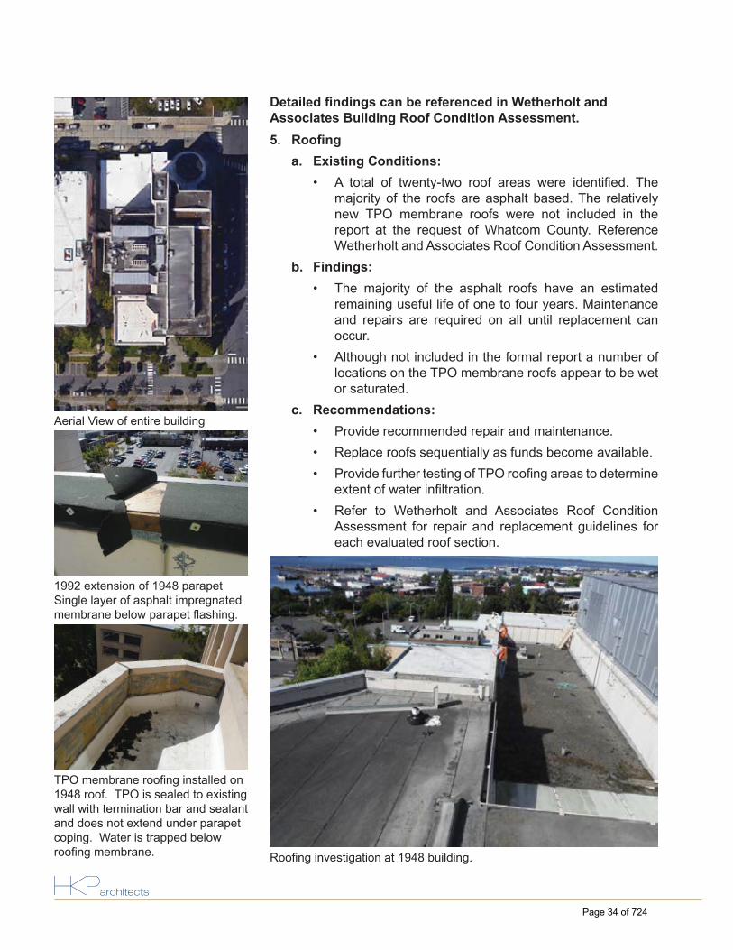
5. Roofi nga. Existing Conditions:
• A total of twenty-two roof areas were identifi ed. Themajority of the roofs are asphalt based. The relativelynew TPO membrane roofs were not included in thereport at the request of Whatcom County. ReferenceWetherholt and Associates Roof Condition Assessment.
b. Findings:• The majority of the asphalt roofs have an estimated
remaining useful life of one to four years. Maintenanceand repairs are required on all until replacement canoccur.
• Although not included in the formal report a number oflocations on the TPO membrane roofs appear to be wetor saturated.
c. Recommendations:• Provide recommended repair and maintenance.• Replace roofs sequentially as funds become available.• Provide further testing of TPO roofi ng areas to determine
extent of water infi ltration.• Refer to Wetherholt and Associates Roof Condition
Assessment for repair and replacement guidelines foreach evaluated roof section.
Aerial View of entire building
1992 extension of 1948 parapetSingle layer of asphalt impregnated membrane below parapet fl ashing.
TPO membrane roofi ng installed on 1948 roof. TPO is sealed to existing wall with termination bar and sealant and does not extend under parapet coping. Water is trapped below roofi ng membrane. Roofi ng investigation at 1948 building.
Detailed fi ndings can be referenced in Wetherholt and Associates Building Roof Condition Assessment.
Page 34 of 724

Existing Conditions And Recommendations Flashing
Page 35 of 724

6. Flashinga. Existing Conditions:
• Flashing types of various materials include: window,parapet, thru-wall, copings and drips.
b. Findings:• In some cases fl ashings have not been installed in a
manner consistent with the Construction Documents.As-detailed stainless steel was replaced with copper.
• No end dams are apparent at window head and jambfl ashing. This is allowing water to enter the wall cavity insome areas, especially at the elevator lobby windows.
• Flexible fl ashing at precast sills may be folded such thatwater is being directed back into the wall cavity.
• Weep tubes at window sills are ineffectively placed andnearly all are blocked.
• Window jamb fl ashing integration with the WRB, whereprovided, is inconsistent.
• No through wall fl ashing is provided at weep holes in thepanelized brick and the weep holes are plugged.
• Weep holes at brick arches are not in the drainage plane.• Internal copper fl ashing is loose laid, not soldered, and
is interrupted by the panel anchors.• Flashing does not cover the upper portion of the EIFS
in certain locations, exposing mesh and allowing waterinfi ltration.
• As-detailed thru-wall fl ashing between panelized brickand brick veneer was not installed.
• There is a lack of fl anged saddle fl ashings at parapetstep downs and coping to walls.
• Many sky facing surfaces lack weather protection byfl ashings.
c. Recommendations:• During envelope replacement provide all necessary
fl ashings correctly designed and installed as per currentbest practices.
1992 Elevator Lobby Window. Poor fl ashing allows water behind EIFS.
1992 EIFS. Reinforcing mesh does not wrap edge of insulation. Inspection blade in breach of fi nish. Flashing does not overlap EIFS.
1992 fl exible fl ashing at window sill. Flashing does not extend to face of brick, corner fold directs water into masonry wall cavity.
1992 EIFS parapet. Sheet metal fl ashings at parapet indentations do not have fully formed end dams. Water is allowed to migrate into the wall cavities at the upturned ends.
Detailed fi ndings can be referenced in Wetherholt and Associates Building Roof Condition Assessment.
Page 36 of 724

Existing Conditions And Recommendations Seismic/Expansion Joints
Page 37 of 724

7. Seismic/Expansion Jointsa. Existing Conditions:
• A seismic/expansion joint separates the varying additionsto the 1948 courthouse. Various materials are useddepending on the confi guration. Vertical joints are fi lledwith backing material and sealant. Horizontal joints atsimilar roof planes follow the original concrete parapetsand it is unclear how they are constructed. Roof to walljoints are spanned with fl exible fl ashing.
b. Findings:• Problematic detailing at areas around the building.
These areas are suspected of leaks.• Seismic end joints are decayed or separated in areas
and open to water entry.• Expansion joint materials are decaying.• Confi guration appears to not provide full separation
between additions and original construction.c. Recommendations:
• During envelope replacement, replace all seismic/expansion joints, confi rming adequate detailing to meetseismic separation.
Expansion joint sealant split due to age deterioration.
Original 1948 parapet between 1948 and 1972 roofs. Roofi ng stops at the vertical faces with no metal parapet coping.
Reliance on exposed sealants to provide water stopping at section of 1948 concrete cut back for newer construction.
Multiple roofi ng and fl ashing materials.
Detailed fi ndings can be referenced in Wetherholt and Associates Building Envelope Condition Assessment.
Page 38 of 724