Embed Size (px)
Citation preview
What’s New in
EDGECAM 2020
This document highlights new product features and enhancements in EDGECAM 2020.
To run EDGECAM and Part Modeler 2020, the maintenance expiry date in the license must be April 2019 or later.

www.edgecam.com
What's New in EDGECAM 2020 2 of 39
Contents
‘WHAT’S NEW’ DOCUMENT OVERVIEW .................................................................................................................. 3
IMPORTANT INFORMATION .................................................................................................................................... 4
Manufacture Enhancements
NEW GUN DRILLING CYCLE ........................................................................................................................................ 5
NEW THREAD PROFILING CYCLE .................................................................................................................................. 5
ADVANCED 5 AXIS IMPROVEMENTS ............................................................................................................................. 6
GENERAL QUILL ENHANCEMENTS ................................................................................................................................ 8
QUILLS ON MULTI TASK MACHINES ............................................................................................................................. 9
NEW MILLING TOOL TYPES ...................................................................................................................................... 10
EDGECAM INSPECT IMPROVEMENTS........................................................................................................................ 10
ROUGHING CYCLE - ROUGH WAVEFORM CHIP PREVENTION OPTION ADDED ...................................................................... 12
FINISH TURNING - STAND OFF AVAILABLE FOR UP CUTTING ........................................................................................... 12
FINISH GROOVE - BREAK ORIENTATION ANGLE ............................................................................................................ 13
HOLE CYCLE - XY OFFSET ADDED TO HELICAL HOLE ...................................................................................................... 13
CREATE SEQUENCE - ABILITY TO SET DATUM OFFSET FOR PART DATUM ........................................................................... 14
CAD Support Enhancements
SUPPORT FOR THE LATEST CAD VERSIONS ................................................................................................................... 15
Code Wizard Enhancements
SINGLE QUADRANT FOR RADIAL ARCS ........................................................................................................................ 16
Code Generator Enhancements
SYSTEM VARIABLES FOR GUN DRILLING ...................................................................................................................... 17
ToolStore Enhancements
EDGECAM TOOLSTORE - NEW MILLING TOOL TYPES .................................................................................................. 18
Important Licensing Changes
LICENSE WIZARD - CONFIGURE NETWORK LICENSES ...................................................................................................... 20
OTHER IMPROVEMENTS TO LICENSE WIZARD .............................................................................................................. 20
MAINTENANCE DATABASE REPORT....................................................................................................................... 21
NEW FEATURES IN VERSION 2019 R1 .................................................................................................................... 22

www.edgecam.com
What's New in EDGECAM 2020 3 of 39
‘What’s New’ Document Overview
Purpose of this Document and Other Sources of Information
The purpose of the document is to highlight new and changed items in the current release. Non-release specific information such as installation and licensing information, system requirements and CAD Links information can be found in the relevant document.
For help with your installation, please refer to the Installation Guide. This is available from the DVD or the Help sub-menu in the EDGECAM program group.
For help with licensing your standalone or network license, please refer to the Licensing Guide. This is available from the Help sub-menu in the EDGECAM program group, the CLS menu and the License Manager dialog.
For information on system requirements and supported CAD systems, please refer to the Installation Guide.
Targeted Information inside EDGECAM and Other Programs
In addition to this document, ‘targeted’ information on new items is available in the dialog help and user guides for other applications. This allows you to focus on new features/enhancements for a specific program or the cycle you are currently working on, for example.
Dialogs that have new functionality or where the cycle behaviour has changed have an additional ‘What’s New’ tab in the help. This explains what has been added to the dialog or changed in this release.
What’s new topic(s) have been added to help files for other programs, such as Code Wizard, Code Generator, and ToolStore etc. This only lists new functionality for that program, allowing you to focus on those items.
The Development History of EDGECAM
Additional functionality and enhancements are developed with each release of EDGECAM software. For an overview of new features and enhancements in the last release, please refer to New Features in Version 2019 R1.
For a summary of new features in previous releases, please visit the History section of the EDGECAM website.

www.edgecam.com
What's New in EDGECAM 2020 4 of 39
Important Information
Part Modeler
This release will be the last version of Part Modeler to be supported or sold. We will be recommending that our customers move on to Designer.
Windows 7 Support
Microsoft will be ending extended support by January 2020. We therefore expect EDGECAM 2021 to not support Windows 7.
We would recommend updating to Windows 10 Build 1803 or 1809.

www.edgecam.com
What's New in EDGECAM 2020 5 of 39
Manufacture Enhancements
New Gun Drilling Cycle
EDGECAM now provides a Gun Drilling cycle. This dedicated interface aims to simplify the information contained in the dialog and provide the same functionality as in the Deep Hole tab of the Hole cycle but with some additional controls.
Note: The Deep Hole tab in the Hole Cycle dialog will become obsolete and will be retired in the near future.
New Thread Profiling Cycle
EDGECAM now provides a Thread Profiling cycle. This new cycle has been implemented for this release providing a way to machine large screw threads when the profile is too large to cut with a regular threading insert.

www.edgecam.com
What's New in EDGECAM 2020 6 of 39
Advanced 5 Axis improvements
Support for Barrel Cutters
The EDGECAM ToolStore and Tool Change command now supports Barrel cutters. This can be used by the Advanced 5 Axis cycle for the Surfaces and SWARF machining.
Side tilt by contact point
This feature provides a convenient, new tilting option for 5-axis machining. It allows you to define the tool axis tilting by specifying a contact point on the tool profile that is tangential to the machining surface along the toolpath. In addition to the contact point, a lead/lag angle can be specified to completely determine the orientation.
This feature significantly simplifies the operational setup, especially for tools with a complex profile geometry, e.g. barrel tools. The contact point is specified either by the axial distance or the distance along the tool profile starting on the tool tip. The user can specify a static contact point or a dynamic range, so that the contact point changes along the contour from the range start to the range end.
You can find this option under:
• Tool axis control Tab.
• Select - Tool axis will be tilted relative to cutting direction.
• Spherical tools should be defined.
• Set side tilt by the Contact point.
For example, a barrel cutter could set the contact point on the cutter to 0.3 to 0.5 of the flute height and, therefore, keep the cutting the range on the main radius of the cutter.
Existing toolpath - Notify if the toolpath was trimmed
When Strategy is Convert 3 to 5, a notification can be given when the toolpath was trimmed due to rest collisions.
Existing toolpath - check for rest collisions
When Strategy is Convert 3 to 5, a notification can be given of any remaining collisions.

www.edgecam.com
What's New in EDGECAM 2020 7 of 39
Existing Toolpath - Links
On Strategy Convert 3 to 5 axis, new links are created after trimming the toolpath whenever a collision between the tool and the workpiece can occur. The user can change the gap links settings for trimmed toolpaths to:
• Clearance area.
• Clearance blend spline.
• Rapid distance.
These types can be used together with the lead in/out option.
Existing toolpath - smoothing
Smoothing is an operation based on interpolation for optimising the contour while keeping the tilt angles within a limited range.
Smoothing by tilt angles tries to shape the converted toolpath (which may have some deviations) into a clearer one. This option modifies the path in which the contour's vectors are different to ensure that the tool moves fluently.
Feed rate for direct/spline links
You can now control the feed rate for the type of links (direct or blend spline).
Available for Surface based strategies on the utility tab.
SWARF Gouge check - Additional surfaces
You now have the ability to add extra gouge checks for the SWARF machining strategy.

www.edgecam.com
What's New in EDGECAM 2020 8 of 39
General Quill Enhancements
For this release, a new Quill Control dialog and the possibility to add auxiliary Z axes to MTM post processors have been introduced:
Quill Control
The new Quill Control dialog on the Move Tool menu provides centralised control over the Auxiliary axis moves, such as which axis is active after the move is completed and which axis (main or auxiliary) should move first.
Tracking Window
A new feature has been added to increase the control over the position of the quill, which is the possibility to track its current position through the Tracking window. This is useful when simulating the auxiliary axis movements internally. The same enhancement applies to auxiliary X axes.

www.edgecam.com
What's New in EDGECAM 2020 9 of 39
Quills on Multi Task Machines
Auxiliary Z axes
Auxiliary Z axes can now be added when building MTM post processors. Previously, the Auxiliary Axes options where unavailable when Turning Capability was selected.
It is possible to add these auxiliary devices to Vertical and Horizontal Mill Turn machines, either in the Table or in the Head. This allows for the support of VTL Crossrail configurations.

www.edgecam.com
What's New in EDGECAM 2020 10 of 39
New Milling Tool Types
For this release, three Milling Tool Types have been added which can be selected from the General tab of the Milling Cutter dialog:
• Barrel Cutters for 5 Axis Machining.
• DoveTail and Double Angle Tools for Chamfer generation.
For Barrel tools, the Barrel Cutter Data dialog can be accessed from the More tab allowing the Upper Diameter, Lower Diameter, Maximum Diameter and Profile Radius to be specified.
For Dovetail and Double Angle tools, Diameter and Angle can be specified on the General tab; Flute Length on the More tab. Note that the Included Angle setting in the ToolStore is named Angle in EDGECAM.
For all tools, you can, optionally, specify a Corner Radius.
EDGECAM Inspect improvements
As part of the ongoing improvements to EDGECAM Inspect, a number of enhancements have been implemented:
• Updates on the Ribbon
In order to follow the EDGECAM Workflow, the EDGECAM Inspect commands have been reorganised in the following areas of the ribbon:
• Features tab.
• Machining tab.
• NC Code tab.
• Split Options menu
The Options menu on the Features tab is now called Inspection Defaults and contains all of the default options for new features and tolerances.
A second Options menu (Output Options) has been added to the NC Code tab which contains all of the output options.
• Settings related to report on the Results dialog
The options related to reporting can now be controlled directly from the Results dialog.
• Safe Retract controls
The Inspection Cycle now provides options to control what the cycle does before indexing the probe tool and at the end of the cycle.

www.edgecam.com
What's New in EDGECAM 2020 11 of 39
• Ability to use the Alternate Solution
EDGECAM Inspect now offers an option to control the way that the probe indexes to a feature.
This option adds another rotation to the index move by rotating the workplane and, therefore, the part, through 180°, the prefix 'alt' is added to this new workplane.
• Export / Import points
Two new commands have been added to EDGECAM Inspect; Export and Import points:
• The Export command allows the user to export points to any text format (usually .xml file) and apply a processor (plugin) to translate them.
• The Import command allows the user to import points from other applications such as PCDMIS and 3DFI. The command reads the XML file created by a processor from a text file.
• Improvements in the Angle To Axis feature
The Angle To X Axis, Angle To Y Axis and Angle To Z Axis commands have been replaced by a single Angle To Line command.
The Reference Axis is set automatically depending on the command picks but, if necessary, it can be changed by editing the feature. In addition, the feature direction can be controlled while creating the feature; the second pick determines the feature direction.
• Changes to Constructed features
• Constructed features have been renamed. Distance To Line is Distance and Relative Angle is Angle.
• Line can be created for more than two single-pointed features allowing Straightness to be evaluated:
Note: To evaluate Straightness, create the line feature by picking more than two single-pointed features and then check the Straightness option by editing the feature.
• Distance can be applied to any combination of single-pointed, constructed line and plane. We can measure distance between points, distance to line, distance between lines, distance to plane and distance between planes.
• Convert Circular feature into Arc feature
Circular features can be converted into Arc features, and Arc features can be converted into Circular features, by editing the End Angle:
• If End Angle is blank, the feature is treated as a Circle.
• If End Angle is not blank, the Circle is converted to Arc.
• Allow index for non-indexable
This improvement allows the user to re-assign Cone, Cylinder, Hole and Rectangle features to any other workplane if the plane of the workplane is parallel to the feature. It may be very useful, for example, to re-assign features in the sub spindle.
• Option to use last block of data (between operators 14 and 9) in the result file
EDGECAM Inspect now uses the last block of data (block between operators 14 and 9) in the journal file to evaluate results.
It is an important improvement because some controllers do not have a function to delete the journal file and it may contain several blocks of results where the last one is the most important.
• Associative to Feature when no solid
Associative clearance can now be used in the Inspection Cycle even without a solid. When Associative is On, the clearance level is calculated relative to the highest point of the feature.

www.edgecam.com
What's New in EDGECAM 2020 12 of 39
Roughing Cycle - Rough Waveform Chip Prevention option added
When roughing boss regions, the toolpath can generate collapsed regions that form a peg of material. These thin walls become weak, vibrate and break off, potentially causing tool damage.
For this release, we have introduced a Chip Prevention option to the Rough Waveform strategy.
Selecting Chip Prevention enables Across moves to remove narrow bits of stock and prevent them breaking off.
Finish Turning - Stand Off available for Up Cutting
The Stand Off option is now available for Up Cutting or Down Cutting. Previously, it was only available for Down Cutting.
When machining parts with corners that were bigger than the tool insert, the tool would easily rapid into the stock. The user can now configure the Finish Turn cycle to avoid this type of collision.

www.edgecam.com
What's New in EDGECAM 2020 13 of 39
Finish Groove - Break Orientation Angle
For this release, a new Break Orientation Angle option has been added to the Control tab of the Finish Groove cycle. This functionality already exists for other turning cycles.
The functionality allows you to break the input geometry when a radius/chamfer is not provided. Values set in this field will be applied to the First Entity in the geometry as defined by the user when selecting the geometry.
Note: The option will not be available until Include First and Last Entity is selected.
When generating the toolpath, the red angles in the image will be avoided so that the part is not damaged.
Hole Cycle - XY Offset added to Helical Hole
The Helical strategy of the Hole Cycle now has the ability to specify an XY Offset. This allows the cycle to leave material for either a secondary cycle to finish the hole or for a subsequent operation.
Note: There is no intention to add Z Offset; any offset at the bottom of the hole should be controlled with depth parameters.

www.edgecam.com
What's New in EDGECAM 2020 14 of 39
Create Sequence - Ability to set Datum Offset for Part Datum
When creating a Turning Sequence, the user now has the ability to set an offset to the datum on either or both spindles using Datum Offset. When the offset is set, the Turn and Main Spindle do not need to be at the same location.

www.edgecam.com
What's New in EDGECAM 2020 15 of 39
CAD Support Enhancements
Support for the latest CAD versions
The following CAD / file versions can now be loaded:
• Parasolid Library – Update to 31.1.188
• ACIS R1 - 2019 1.0
• Datakit Library – Upgrade to DTK-2019.2
• Solidworks 2019
• Inventor 2019
• Spaceclaim 2019
• Creo 5
• Granite - Creo 5 support
• NX 11 0 NX 12.0.0
• CATIA V5R8 – V5-6R2018

www.edgecam.com
What's New in EDGECAM 2020 16 of 39
Code Wizard Enhancements
Single Quadrant for Radial Arcs
Previously, Code Generator would only output full radial rotary arcs. However, as some machines cannot execute full radial rotary arcs, a new Single Quadrant option has been added to the Rotary Axes tab of the Machine Configuration dialog. Note that this option is only available when Radial Arcs is selected.
With the Single Quadrant option selected, the output now breaks arcs into quadrants.
A comparison of the NC code can be seen opposite.

www.edgecam.com
What's New in EDGECAM 2020 17 of 39
Code Generator Enhancements
System Variables for Gun Drilling
Two new system variables (DEEPHOLE and ENTRYDEPTH) have been added to the following Code Generator macros:
• Milling Macro Reference (MACRO 9 - DRILL CYCLE).
• Turning Macro Reference (MACRO 9 - DRILL CYCLE).

www.edgecam.com
What's New in EDGECAM 2020 18 of 39
ToolStore Enhancements
EDGECAM ToolStore - New Milling Tool Types
Three Milling Tool Types have been added to the ToolStore:
• Barrel Cutters for 5 Axis Machining.
• DoveTail and Double Angle Tools for Chamfer generation.
For Dovetail and Double Angle tools, you can specify a Diameter, Included Angle and Flute Length. Note that the Included Angle setting in the ToolStore is named Angle in the EDGECAM Tooling dialogs. Optionally, specify a Corner Radius.

www.edgecam.com
What's New in EDGECAM 2020 19 of 39
For Barrel tools, you can specify an Upper Diameter, Lower Diameter, Flute Length and Profile Radius or specify a Max Diameter from which the Profile Radius can be derived. Optionally, specify a Corner Radius.

www.edgecam.com
What's New in EDGECAM 2020 20 of 39
Important Licensing Changes
License Wizard - Configure Network licenses
The License Wizard has been enhanced to enable users to configure network licenses after selecting a network license server. Previously, the user could only select the server and would then have to run License Manager to Configure Network licenses:
• Selecting the Save button saves a license configuration, not a Profile.
• Selecting the Save As button allows the user to save the license configuration as a Profile.
Other improvements to License Wizard
• The brand name and the name of the selected network license server are displayed in the Title Bar.
• The new Server button allows the user to switch between different network license servers.
• The check box to enable profile selection on startup is included in the License Wizard.
Note: Network licenses and profiles can still be configured in License Manager.

www.edgecam.com
What's New in EDGECAM 2020 21 of 39
Maintenance Database Report
For a full list of maintenance items resolved in EDGECAM 2019 R1, please refer to the Maintenance Database Report.

www.edgecam.com
What's New in EDGECAM 2020 22 of 39
New Features in Version 2019 R1
Below is an overview of new features and enhancements in the last release.
For a summary of new features in previous releases, please visit the History section of the EDGECAM website.
Manufacture Enhancements
Finish Turning - Up Cutting option
An Up Cutting option has been added to the Cut Direction option of the Control tab which, when checked, causes the selected turn profile to be split into steep and shallow regions; forcing the Cut direction on the steep regions to be Up Cut, which is the preferred cut direction for some tooling inserts.
New Parting Off Cycle
A new Parting Off cycle has been introduced for this release which is used to separate the machined component from the stock:
• The cycle will work for both external and internal Parting Off.
• The cycle will work for main and sub spindles.
• The cycle will work for upper or lower turrets
• For internal Parting Off, the cycle will only work with Current Stock.

www.edgecam.com
What's New in EDGECAM 2020 23 of 39
Finish Groove - Start and End Extensions
It is now possible to specify Start and End extension values in the Leads/Links tab of the Finish Groove cycle. Previously, this was only possible by dragging the Start/End points.
Note: Positive or negative extension values can be applied.
Rough Turn - Added Stock Runout Angle and Length
The Stock Runout option in the Rough Turn cycle was available in previous versions of Edgecam. This parameter allowed each cutting pass to be extended out towards the stock boundary. For this release, two new options have been added:
• The Runout Angle will modify the angle of the extension. In the example, an angle of 10º is used in the first image and an angle of 70º is used in the second image.
• The Runout Length can be used when the runout needs to be trimmed because it would be too long in some situations.
Note: The Runout Length does not have a higher priority than the original Runout element length and will only be applied if bigger than the original element length.

www.edgecam.com
What's New in EDGECAM 2020 24 of 39
Thread Turning - Added Safe Distance
For this release, a new Safe Distance setting has been added to the Depth tab of the Thread Turning cycle.
This value represents the safe distance between passes which is always applied orthogonally to the input profile. In previous versions, this parameter was set from the Miscellaneous menu but it is now available in the dialog.
Controlling spindle C-angles on docking
For this release, we have provided the capability to control the Main and Sub spindle C-angles during a Spindle Setup.
New Main Spindle and Sub Spindle C-Angle modifiers have been added to the General tab of the Spindle Setup dialog which will be available provided the machine has C axis control capabilities.
When performing a transfer, the following events will take place:
• Donor spindle is selected.
• Donor spindle is rotated, using Move Angular, to the required angle.
• Receiving spindle is selected.
• Receiving spindle is rotated, using Move Angular, to the required angle.
• Main spindle is selected.
• Sub spindle moves to approach and then final grip position.
• Component is handed over to the receiving spindle.
• The component (stock, solid, features) is now rotated by the resultant angle of the two spindles, replicating the physical resultant rotation that took place in the machine.
Note: If the machine has an offset Sub Spindle (in X), controlling the C-angle is not supported.

www.edgecam.com
What's New in EDGECAM 2020 25 of 39
Chamfering - Gouge Check Gap option
In order to avoid unwanted gouges on edges that were not selected for the cycle, a new Gouge Check Gap option has been added to the General tab of the Chamfering cycle. The option is only available when Chamfer Type is set to Deburring.
This helps the user to control how close to the wall the tool can go. By definition, the Gouge Check Gap is the distance above the selected edge where the tool is no longer allowed to gouge the model:
• Leave empty for the default value (half of the Chamfer Depth).
• Use zero to disable gouge checking. Existing parts have a default value of zero which disables the gouge checking.
Collision Check for Hole Cycle (obstructed holes)
In the Hole Cycle, the Fixture Collision Check will raise the Level of link moves in order to avoid collisions between the Tool / Holder and the Fixture. In Edgecam 2019 R1, it will also avoid all Holes that are obstructed by a Fixture:
• In Longhand output, the output coordinates will follow the toolpath.
• In Canned output, the coordinates of the missing holes will be removed from the NC file. The previous behaviour will be maintained with regard to the Link moves where one Canned Cycle will be split into multiple Canned Cycles in order to correctly control the Link moves in the NC code.
• A message will be displayed in the Feedback window to warn users that holes have been avoided: 'n holes have not been machined as the tool would collide with a fixture'.
Note: Users may see differences during Sequence regeneration. Since it follows the configuration of the last Update Fixtures instruction, there could be situations where this will need to be adjusted.

www.edgecam.com
What's New in EDGECAM 2020 26 of 39
Profiling - Behaviour change if using CRC Geometry path when a Taper Tool is active
In 2018 R2, a check was added to the Profiling cycle which disallowed the CRC Geometry path when a Taper Tool was active. Regeneration of existing parts that included this combination would stop and the user would be prompted to select CRC Compensation = Centre Line or None; the safe option.
For this release, this behaviour has been changed to allow existing parts with this combination to regenerate without stopping and write a warning to the feedback window instead which is the same as releases prior to 2018 R2.
We now also allow this combination for a new cycle but issue the following warning:
Extreme care should be taken when using this combination as in some situations the back offset can self intersect and the resultant toolpath can gouge the component and this is not detected in the Simulator.
The Profiling Cycle CRC back offset is based on the major diameter of the tool; some users adjust the major diameter / radius on the machine controller or define the tool in Edgecam with the major diameter set to the contact point diameter. To ensure that these methods continue to work we now allow this combination of Taper Tool and CRC Geometry path with the caveat that extreme care should be taken.

www.edgecam.com
What's New in EDGECAM 2020 27 of 39
Edgecam Inspect improvements
As part of the ongoing improvements to Edgecam Inspect, a number of enhancements have been implemented:
• Switch from Wilcox Gateway to PCDMIS fit libraries
Edgecam Inspect 2019 R1 will start using the PCDMIS fit libraries, which have certified and approved math, and include some new functionality such as the evaluation of Cylindricity and Conicity.
• Associative Clearance
The cycle now offers an option for the Clearance to be associative with the solid model:
• Check the option for the Clearance level to be incremental from the highest point of the solid and associative to the solid model.
• Uncheck the option for the Clearance value to be relative to the active Work Datum.
• Option to Create Layers
An option has been added to the Options menu which allows the user to choose between creating the features on predefined layers or at the active layer.
• Evaluation of Axis Deflection
Edgecam Inspect now offers an option to evaluate the Axis Deflection of 3D Cylinders/Cones (more than 1 level) and Plane features.
The option to calculate and show it in the report file is found under the Advanced tab.
In addition, more feature properties are shown in the report, such as number of levels and touches per level.
• Allow Edge feature in rotary faces
Edge and Edge Angle features can now be created in rotary faces, for example, between cones and cylinders.
• Improvements for Distance Constructive features
Distance To Point and Distance To Line features can now be created based on Edge and Rectangle features.
Also, it is now possible to set the Distance Type prior to creating the feature.
• Manual features
In Edgecam Inspect 2019 R1, it is possible to create inspection features by entering manual coordinates.
It allows the user to create features even when not using a solid model or on a model with incorrect geometry.
To use it, check the Manual Input option (Options menu > Features tab) and then, when creating a feature, a dialog will displayed allowing you to enter the coordinates.
• Allow Arc feature to be indexable
Arc features can now be measured with any stylus orientation.
The two limitations are that the arc must not exceed 180 degrees and the arc must be processed collision free with the requested tool orientation.
• Constructed Circle
Constructed Circle allows the user to create construct circular features (circle/arc) based on existing single pointed features.
• Option to select type of Work offset update
Work Offset update now has two options:
• Type which defines which table you want to update (work offset or error compensation).
• Axes which allows you to select which axes are to be considered when updating.

www.edgecam.com
What's New in EDGECAM 2020 28 of 39
• Hide the Processor section of Options dialog
We have removed the Processor section from the Options dialog.
Demo Mode and External are now turned off by default.
Setting the EIShowProcessor PCI variable to 1 enables this section to be displayed again.
• Custom Report
Edgecam Inspect now supports custom reports.
This improvement allows the user to develop his own plugin and generate the report file of the measurements customised to their requirements.
• Support of canned cycles
Edgecam Inspect Canned Cycle was developed to allow probing cycles to be implemented.
www.edgecam.com
What's New in EDGECAM 2020 29 of 39
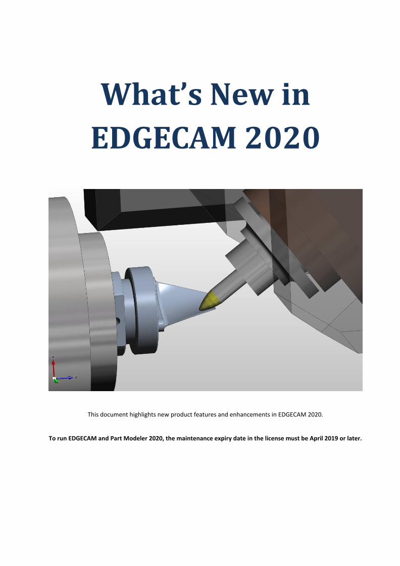
Additive / Hybrid machining
Edgecam now officially introduces support for additive technology, which, when combined with the existing 'material removal' cycles, forms what the industry calls Hybrid Manufacturing.
The functionality is fully licensed from 2019 R1 and available for purchase. The 'Edgecam Additive Machining (ENADD-M) module requires Advanced or Ultimate as pre-requisites.
The main physical aspect of this is that the Additive Head needs to be vertical and the surface horizontal or near horizontal; there is little adhesion to the wall although undercuts can be constructed gradually:
• In Edgecam, additive cycles can be built using virtually any cycle, or even manual moves. Leads, links and rapid moves are non-additive,
• Advanced cycles, such as Rotary and 5-axis, can also be used, where the same characteristics apply, though with less and more difficult control.
• A dedicated 'filling up' cycle is available, Additive Lace, designed to construct geometry on a layer-by-layer basis, bottom-to-top.
The Additive Lace cycle has the following features:
• Outer Contour
Toolpath buildup can result in discrepancies and runoffs on the external edges where the melt pool is more vulnerable to gravity effects.
For this reason, an Outer Pass is required, either before or after the internal region is filled. This is similar to the Finish Pass generated by a Flat Land Finishing cycle.
When enabled, one or more outer passes, following the exact contour of the selected geometry including offsets and boundaries, will be created for each layer.
• Undercut / Negative drafted walls
To enable undercut shapes to be created, an Undercut model option has been included that will ensure that the cycle does not fill up the voids
• Link control
Long links as Clearance will make the tool retract to clearance at rapid rate. Longs links as Optimised will make the tool retract by Safe Distance height, and travel at high feed rate to the next point,

www.edgecam.com
What's New in EDGECAM 2020 30 of 39
Additive Tool
For this release an Additive tool has been added to the toolchange:
• On the General Tab, set Tool Type to Additive and select one of the Additive Sub Types: Powder Deposition, Wire Deposition, Metallization or Extrusion.
• On the General Tab, Diameter and Corner Radius define the dimensions of the additive bead, where the corner radius is applied to the uppermost side; optionally, a Flute Length can be defined on the More tab.
• On the Loading tab, Shank Length is used to define the length of the mixing jet from the nozzle to the top of the bead, in the case of Powder Deposition. Overall, it is the distance between the nozzle and the region where the material deposits on the part.
• The More Tab includes additional technology additive parameters that can be used to control the additive process and can be directly output to the NC using Code Wizard.

www.edgecam.com
What's New in EDGECAM 2020 31 of 39
New Wire Technologies
For this release, new Wire Technologies have been added for the following machine models:
Mitsubishi
• FA10 BRD-B13W031-A10.
• FA10 BRD-B13W031-A13.
• FA20-V, BRD-B13W042-A8.
• FA30 BRD-B13W032-A10.
• MP1200 BRD-B13W135-A1.
• MP1200 BRD-B13W146-A5 AdvancePlus 2.
• MP1200 BRD-B13W146-A6 AdvancePlus 2.
• MP1200 BRD-B13W146-A7 AdvancePlus 2
• MP2400 BRD-B13W136-A1.
• MP2400 BRD-B13W147-A5 AdvancePlus 2.
• MP2400 BRD-B13W147-A6 AdvancePlus 2.
• MP2400 BRD-B13W147-A7 AdvancePlus 2.
• MP2400 DCUBES BRD-B13W164-A3 Advance V10.
• MP4800 BRD-B13W137-A3.
• MV1200R BRD-B13W118-A2.
• MV1200R BRD-B13W118-A6.
• MV1200R BRD-B13W142-A0 Advanceplus 2.
• MV1200R BRD-B13W150-A7 Advanceplus 3.
• MV1200R BRD-B13W150-A8 Advanceplus 3.
• MV1200R D-CUBES BRD-B13W159-A5.
• MV1200R D-CUBES BRD-B13W159-A7.
• MV1200S BRD-B13W117-A2.
• MV1200S BRD-B13W141-A0 Advance 2.
• MV1200S BRD-B13W149-A5 Advance 3.
• MV1200S BRD-B13W158-A4.
• MV2400R BRD-B13W152-A8 Advanceplus 3.
• MV2400S BRD-B13W119-A2.
• MV2400S BRD-B13W119-A6.
• MV2400S BRD-B13W143-A0 Advance 2.
• MV2400S D-CUBES BRD-B13W160-A4.
• MV2400S-DC_BRD-B13W160-A7.
• MX600 BRD-B13W123-A10.
• MX600 BRD-B13W123-A9.
Fanuc
• Robocut Alpha C4001A.
• Robocut Alpha C400IB.
• Robocut Alpha C600IB.
• Robocut Alpha C800IB.
• Robocut Alpha FANUC0ID.
• Robocut Alpha FANUC1ID.
Makino
• Makino technology has been updated to V33.
ACorange
• A technology database has been added for ACorange.

www.edgecam.com
What's New in EDGECAM 2020 32 of 39
Change Notification Improvement for the Solid's File
Change Notification informs the user if a later version of the solid's file within the .ppf file is detected; this check is activated by the Change Notification setting on the Solids tab of the Preferences dialog.
In previous Edgecam versions, when opening a .ppf file containing a solid's file on an inaccessible path, there was a delay before Edgecam became active. The delay was caused by the change notification check not being able to locate the solid's file.
We have, therefore, changed the way that Change Notification works by disconnecting it from the File Open process and running it in the background. If it detects that the original solid's file is not accessible, it disables the Change Notification for the current Edgecam part and informs the user that the link to the original solid's file has been lost.
Performance improvements
Roughing Waveform calculation time
We have improved the Roughing Waveform calculation time in at least 15%, some cases up to 60%. We have improved the calculation time mainly for the known performance bottlenecks, such as usage of small stepover, narrow channels and heavily curved model regions.
Reduce regeneration on turning
Turning sequences will now cause less involuntary regeneration, especially in some specific commands like Angular Move.
Reduce prismatic geometry data
With Prismatic Geometry enabled, we only process the geometry on the model between the level and depth of the cycle. This can lead to improved performance on very complex components.

www.edgecam.com
What's New in EDGECAM 2020 33 of 39
CAD Support Enhancements
Support for the latest CAD versions
The following CAD / file versions can now be loaded:
• SpaceClaim 19 (ACIS V28).
• Parasolid version 30.1.247.
• Inventor 2019.
• Designer 2019 R1 (*.vdf).
• Creo 5.0. Note: In order to load Inventor 2019 files, the machine needs to have Inventor or Inventor View 2019 installed.
Cset IGES Loader Retired
The Cset Ci2x IGES loader used in Edgecam and Part Modeler has now been retired.
The IGES loader now defaults to using SolidLink and the redundant Cset modifiers have been removed from the associated Edgecam and Part Modeler dialogs.
Load Designer files without requiring a Solid Machinist option license
It is now possible to load Designer files (*.v_t and *.vdf) into Edgecam without requiring a Solid Machinist option license:
• All Edgecam system licences allow Designer files (*.v_t and *.vdf) to be loaded.
• Feature Finding and Strategies are fully supported for these files on all CAM system licences.
Note: Other solid model files, including Parasolid, cannot be opened in Edgecam unless an appropriate Solid Machinist option license is available.
Load Parasolid Mesh from VDF files
For this release, Parasolid Mesh can be loaded from VDF files; these are triangulated bodies made up of free form faces:
• The Parasolid Mesh bodies are depicted by a green triangulated cube icon in the Feature and Setup Browsers to differentiate between the two types of Parasolid body.
• The Mesh can be machined directly; edges can be picked to define boundaries and the Mesh can also be used to define stocks and fixtures.
• They are unsuitable for Feature Finding. The Features Ribbon interface does not differentiate between a Parasolid Mesh and Standard Parasolid and, therefore, for Parasolid Mesh, the Feature Find commands cannot be hidden and running the commands will fail to find any features.

www.edgecam.com
What's New in EDGECAM 2020 34 of 39
Part Modeler IGES Enhancements
For this release, C-set has been removed and SolidLink will be used, by default, to import IGES files in Part Modeler:
• The 'IGES Import Standard Settings' have been removed.
• A Healing tolerance field has been added to the 'SolidLink Translation Settings'.

www.edgecam.com
What's New in EDGECAM 2020 35 of 39
Code Wizard Enhancements
Inverse Time Feedrate extended support
Inverse Time Feedrate is a method of representing the velocity of a move based on cutting time instead of cutting feed.
Historically, it has been available for 5 Axis output but, in theory, it can be used on any movement provided that the controller supports it and the correct G-code is specified.
For this release, Inverse Time Feed can be used separately in three modes:
• 5 Axis (already existing).
• Planar mode.
• Rotary mode.
The post processor allows these to be configured, as required, in the Machine Parameters dialog.
In the NC-Style area, the Inverse Time Feed G Code has been moved into the G-Codes tab because it is no longer exclusive to 5 Axis.
Note: Your post needs to be updated to the latest template to benefit from this improvement.
The [FEEDMODEGCODE] token also needs to be used appropriately in the respective code constructors.
Some specific cycles will not output inverse time feeds, reverting to the appropriate feed mode G-code. These include:
• Hole cycles (all drilling, helical hole, thread milling).
• Turning cycles.

www.edgecam.com
What's New in EDGECAM 2020 36 of 39
Reversing the Direction of Mounting
In previous versions, the order in which the tools were mounted could not be changed for a revolving turret. For this release, Edgecam includes this capability.
The user needs to change the Turret Axis, in the Machine Tree, in Code Wizard. Changing the Turret Axis, by reversing its vector definition, will change the tool position order (Clockwise / Anticlockwise ordering).
Euler Angles
The ability to output Euler angles for every move was previously restricted, and switchable via a PCI variable. This has now been fully implemented and is available via a "Generate Euler for all moves" machine parameter.

www.edgecam.com
What's New in EDGECAM 2020 37 of 39
ToolStore Enhancements
Edgecam ToolStore - Additive / Hybrid machining
Additive Tools can now be created and stored in the ToolStore; these are listed under the Additive Tab.
There are 4 additive types:
• Powder Deposition.
• Wire Deposition.
• Metallisation.
• Extrusion.
Edgecam has been primarily designed for Additive Powder.
The dimensions entered on the Geometry tab are for that of the additive bead; Diameter, Corner Radius and Flute Length. The Shank Length defines the length of the mixing jet from the nozzle to the top of the bead.
The Technology Tab stores information specific to the additive process.

www.edgecam.com
What's New in EDGECAM 2020 38 of 39
Edgecam ToolStore - Removing Material setting from a Job/Toolkit
For this release, we have added a button to remove the Material setting from a Job/Toolkit.

www.edgecam.com
What's New in EDGECAM 2020 39 of 39
Edgecam ToolStore - Paste Button implemented on Geometry tab for Turning Tools
A Paste button has been added to the Geometry tab for Turning tools which will enable solid insert graphics to be used; this was already available on the Mounting tab for pasting solid holders. The resultant .meg graphic is displayed in Edgecam and Simulator for a more realistic view of the tool. The Toolpath is calculated from the parametric insert definition and, therefore, care must be taken to match the parametric values to the solid insert shape.