Embed Size (px)
Citation preview

What we’ve learned so far about the Stability of Plasma
Confined by a Laboratory Dipole Magnet
M. E. Mauel and the CTX and LDX Experimental TeamsAnnual Meeting of the Division of Plasma Physics
Philadelphia, PA October 30 through November 3, 2006
09/24/2006 11:11 PMMIT Plasma Science & Fusion Center
Page 1 of 1http://www.psfc.mit.edu/
Administration Computers & Networks Calendar Safety Search PSFC Search
Plasma Science & Fusion CenterMassachusetts Institue of Technology
About PSFC Research People Education News & Events Library General Info
The Plasma Science & Fusion Center (PSFC) is recognized as one of the leading
university research laboratories in the physics and engineering aspects of magnetic
confinement fusion.
77 Massachusetts Avenue, NW16, Cambridge, MA 02139
phone: 617-253-8100, [email protected]

AbstractDuring the past decade, new experiments with collisionless plasma confined by magnetic dipoles have been built at Columbia University, MIT, and the University of Tokyo. These have resulted in detailed observations of interchange instability, convective mixing, and high-beta toroidal confinement without magnetic shear.
This poster discusses these new results with the aim of understanding linear, nonlinear, and turbulent plasma physics due to interchange dynamics.
To date, observations show interchange modes to be fixed-boundary modes with broad structures that are easily measured and understood theoretically. Additionally, for a strong dipole magnet, interchange modes create wave-particle kinetics that are essentially one-dimensional. Hence, observations of linear and nonlinear MHD, fast-particle drift-resonances, transport in magnetospheric and fusion systems, and the effects of strong plasma flows are dominated by low-dimensional dynamics and show good agreement between observation, theory, and numerical simulation.

What We’ve Learned…1. Robust ECRH start-up
2. Profile control with multiple-frequency ECRH
3. Gas programming yields high beta
4. Fluctuations have “Fixed-Boundary MHD” structures
5. Wave-particle dynamics are “One-Dimensional”
6. Turbulence spectrum dominated by machine size
7. Levitation causes “dramatic” confinement improvement

Austin Eugenio Ishtak Alex Jen Scott
Acknowledgments
Dmitry
HarryBen
BrianMatt
Jeff

Austin Eugenio Ishtak Alex Jen Scott
Acknowledgments
Dmitry
HarryBen
BrianMatt
Jeff
AlexAlex
DarrenRick
PhilJoe

Dipole Fusion ConceptTesting a New Approach to Fusion and
Laboratory Plasma Confinement
400-600 MWDT Fusion
Levitated Dipole Reactor
30 m 60 m
500 MWDD(He3) Fusion
ITER
Kesner, et. al. Nucl. Fus. 2002

Dipole Fusion Concept
• Advanced fusion fuel…
‣ D-D (3He) with active triton removal
‣ No tritium breeding; simplified fusion technology
• Requires…
‣ High plasma beta
‣ Good plasma energy confinement
‣ Poor particle (i.e. triton) confinement
‣ High-field, high-temperature superconductors

What We’ve Learned #1 to #3:
Dipole Plasmas Are Easy to Make and to Control
1. Robust microwave/ECRH plasma start-up
2. Pressure and density profile control is readily obtained using multi-frequency ECRH
3. Controlling the neutral fueling rate stabilizes hot electron interchange mode and produces high beta quasi-steady anisotropic plasma

LDX (Columbia-MIT)
1200 kA turns565 kg0.34 m
Mini-RT (Univ. Tokyo)
50 kA turns17 kg
0.15 m
World-Wide Levitated Dipole Experiments
RT-1 (Univ. Tokyo)
250 kA turns110 kg0.25 m
Test Beltrami Physics Test Fusion-Dipole Physics
CTX (Columbia)
150 kA turns(Not Levitated)
0.15 m
Investigate Instability- orElectrostatically-DrivenInterchange Mixing
Today’s Dipole Experiments
ECRH Sustained Dipole Plasmas“Artificial Radiation Belt”
with ECRH“Artificial Gravity”
with Radial Current
X-Ray(J. Ellsworth)
High-Beta Trapped Electrons
CTX
Mini-RT
LDX
RT-1

0.6 0.7 0.8 0.9 1 1.1
-0.2
-0.1
0
0.1
0.2
Anisotropic Pressure !p ! 2"
Austin Eugenio Ishtak Alex JenScott
LDX: High Beta on First Shot!
0.2
0.6
-1.0
-0.6
-0.2
0.2 0.6 0.8 1.0 1.2 1.4
Radius (m)
50513029
6.4 GHz
PressureContours
CurrentContours
2.45 GHz
0.4
1.0
Peak pressure “in-between” 2.45 and 6.4 resonance.
Ishtak Karim, PhD 2006
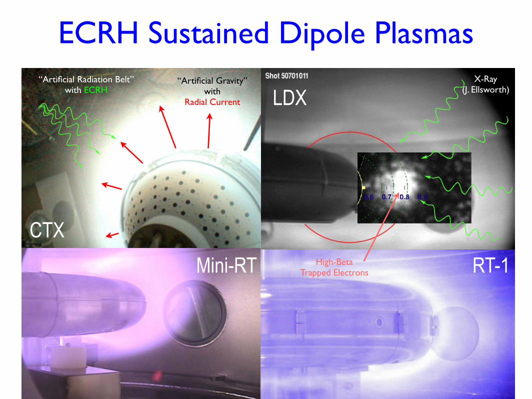
Multi-Frequency ECRH Profile Control…
Plasma PhotosPlasma Photos
Side View
Top View
Only 2.45 Ghz, 3.5 sOnly 6.4 Ghz, 3.5 s
Side View
Top View
Side View
Top View
Both Sources, 5.5 s
Alex Hansen

DENSITY PROFILE CONTROLLED BY ECRH
Time(s)
Shot: 60714033
Shot: 607140342.45GHz only: time=[0-2s] and [4-6s]
2.45GHz & 6.4GHz: time=[2-4s] and [6-8s]
6.4GHz only: time=[0-2s] and [4-6s]
2.45GHz & 6.4GHz: time=[2-4s] and [6-8s]
Ste
epn
ess
Exp
on
ent
Alex Boxer
Peaked
Broad
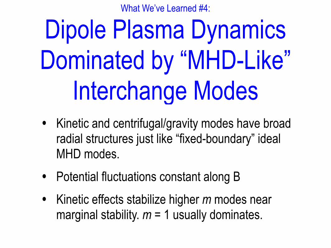
What We’ve Learned #4:
Dipole Plasma Dynamics Dominated by “MHD-Like”
Interchange Modes• Kinetic and centrifugal/gravity modes have broad
radial structures just like “fixed-boundary” ideal MHD modes.
• Potential fluctuations constant along B
• Kinetic effects stabilize higher m modes near marginal stability. m = 1 usually dominates.

Dipole Interchange Modes have Broad Radial StructuresCHAPTER 4. CURVATURE DRIVEN INSTABILITIES IN CTX 57
0.0
0.4
0.8
1.2
0.0
0.4
0.8
1.2
m=3
0.0
0.4
0.8
1.2
1.6
10 20 30 40 50 60 70
r (cm)
Norm
maliz
ed C
orr
ela
tion A
mplit
ude
m=2
m=1
Figure 4.11: Comparison of radial mode structure computed from the nonlinear simulation
(solid lines) with the observed profiles of the normalized correlation amplitudes for m = 1,
2, and 3 as well as the solutions to Equation 4.12.
Hot Electron InterchangeCentrifugal Interchange
(Computed, self-consistent, mode structures shown with solid lines.)
Ben Levitt, PhD 04

Measured Centrifugal Mode Structure(A “Fixed Boundary” MHD Mode)
!60 !40 !20 0 20 40 60!60
!40
!20
0
20
40
60Measured m " 1 Mode
(ɸ ~ Stream function)Ben Levitt, PhD 04

Measured Kinetic Interchange Mode: Structure of Driven Polar Losses
(A Kinetic MHD Mode)
Brian Grierson
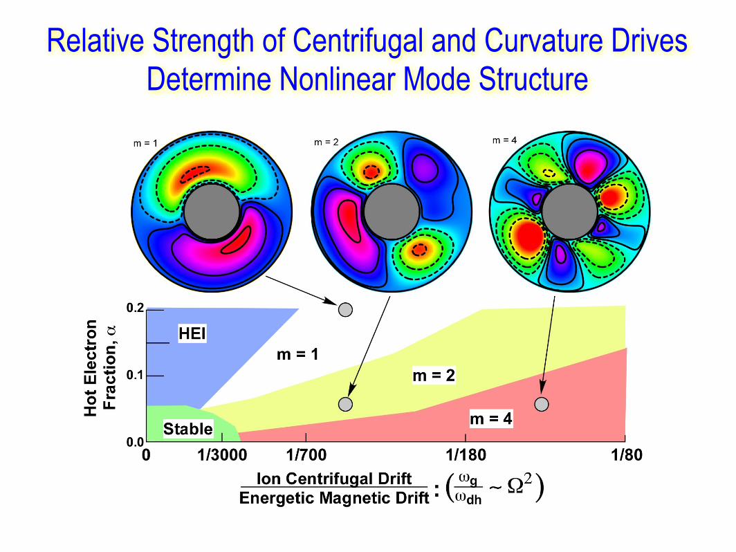
Relative Strength of Centrifugal and Curvature Drives Determine Nonlinear Mode Structure
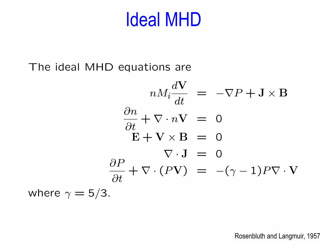
The ideal MHD equations are
nMidV
dt= !"P + J#B
!n
!t+" · nV = 0
E + V #B = 0
" · J = 0!P
!t+" · (PV) = !(" ! 1)P" · V
where " = 5/3.
Rosenbluth and Langmuir, 1957
Ideal MHD

!"#$%&'#()*)+%&,#&-.../).0)1)2)0#34&%(567897688: 69
!"#$%&'()*"%"+,"*-
!"#$%&'$#()*+$,%-.$/+%0)1)+2$3&-41-.$5()+)6%1$7(%').&+89!"#$%&'$#()*+$,%-.$/+%0)1)+2$3&-41-.$5()+)6%1$7(%').&+89! .,$/"%&0'1231'3,&'-3,4"53%%6'013+%&'1$'
"51&,72354&'031"0/6'35'38"3+31"7"16'7$58"1"$59
" :;<;'=$0&5+%*12'358'>$54-",&?'!""#$%&'(#'!'
@ABCDE'AFG;
" H13+%&'I2&5'' ''''''''''?'
I2&,&!!!!!!!!!!!!!!!!"!!!!!!!!!!!#
" ()*"%"+,"3'&J"01'31'2"42K!'1231'3,&'"51&,72354&'
358'"8&3%':L!'+3%%$$5"54'013+%&;
! M$,'#,$/"%&0'1231'3,&'-3,4"53%%6'013+%&'1$'
"51&,72354&'-$8&0'1231'3%0$'23N&'
''''''''''''''''''''''''''''''''?'8"#$%&0'3,&'3%0$'8,"/1'I3N&'
013+%&;
" !,"/1'I3N&0'&J"01'31'$12&,'N3%*&0'$/'#
" (//&710'3,&'7*,,&51%6'+&"54'01*8"&8'+6'O;'
=$4&,0''&1'3%;'
#$) % *" + &
) % *" " &'!
"
(%,-)&*#+,
) $% ,
) $%-*)
-'-).
.)'&
"
Interchange motion
(…ballooning more stable than interchange.)
E · B = 0, E = !"!, axial symmetry, B = "! # "", and theelectric potential, !(", !), is constant along a field line.
The plasma flow is two-dimensional,
V =E#B
B2 = !!̂R#!
#"+
"̂
RB
#!
#!
Low-frequency ($ < $B) plasma dynamics is well described byflux-tube averaged motion!

-2 -1 0 1 2
-2
-1
0
1
2
-2 -1 0 1 2
-2
-1
0
1
20.75 1.25 1.5 1.75 2 2.25
-0.2
-0.15
-0.1
-0.05
0.05
0.1
0.15
UnStable m ! 1: " ! !0.31, 0.14, 0.093"Unstable “LDX”
Pressure Peak
(Radial structure variation always slows mode.)
Typical Ideal Interchange Eigenmodes
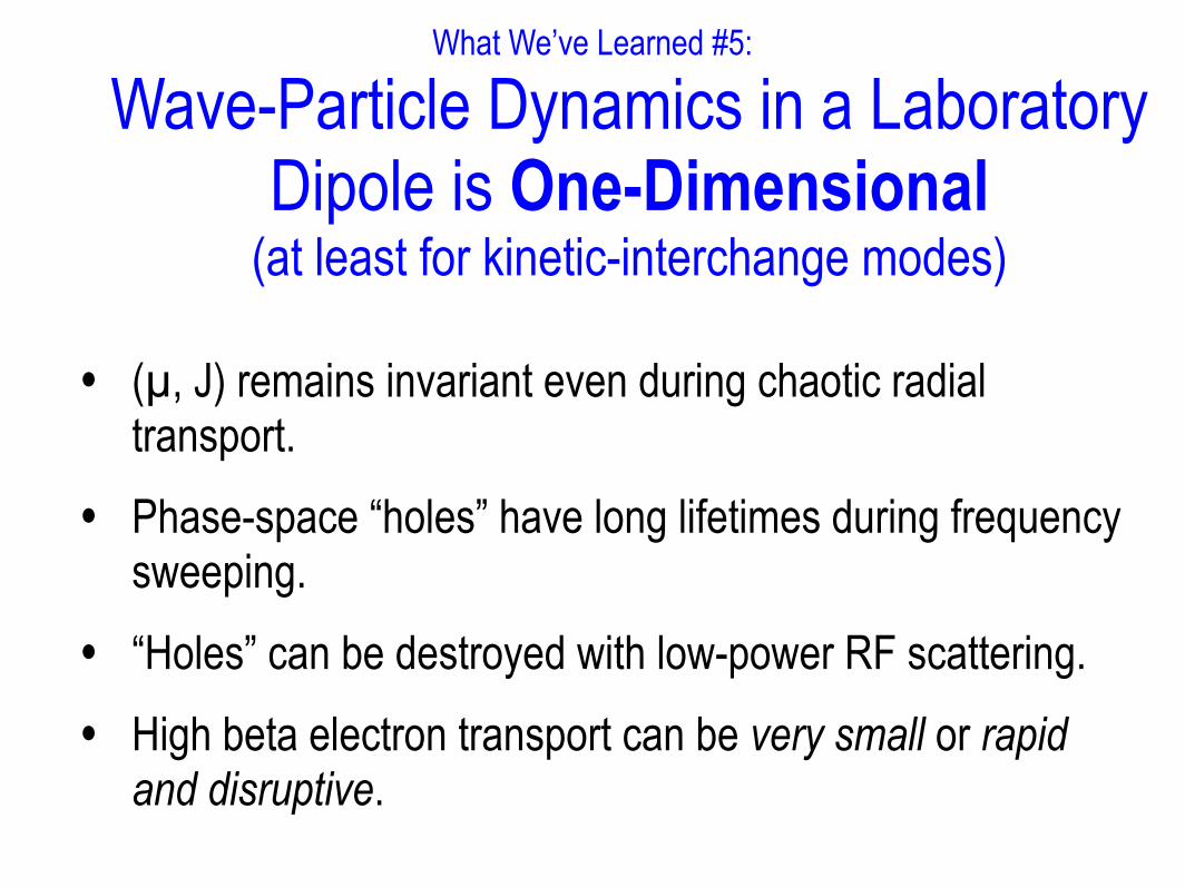
What We’ve Learned #5:
Wave-Particle Dynamics in a Laboratory Dipole is One-Dimensional
(at least for kinetic-interchange modes)
• (µ, J) remains invariant even during chaotic radial transport.
• Phase-space “holes” have long lifetimes during frequency sweeping.
• “Holes” can be destroyed with low-power RF scattering.
• High beta electron transport can be very small or rapid and disruptive.
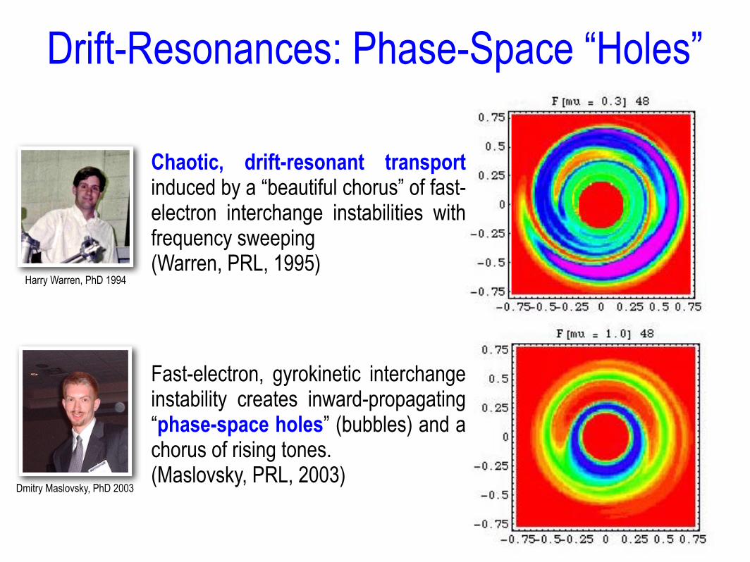
Drift-Resonances: Phase-Space “Holes”
• Chaotic, drift-resonant transport induced by a “beautiful chorus” of fast-electron interchange instabilities with frequency sweeping (Warren, PRL, 1995)
• Fast-electron, gyrokinetic interchange instability creates inward-propagating “phase-space holes” (bubbles) and a chorus of rising tones. (Maslovsky, PRL, 2003)
Dmitry Maslovsky, PhD 2003
Harry Warren, PhD 1994
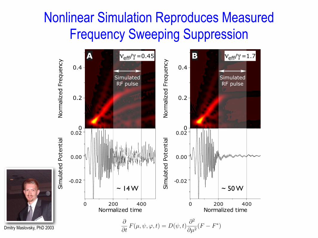
Nonlinear Simulation Reproduces Measured Frequency Sweeping Suppression
0.4
0.2
0
0 200 400
B
Simulated
RF pulse
-0.02
0.00
0.02
0.4
0.2
0
0 200 400
!eff/"=0.45A
Simulated
RF pulse
-0.02
0.00
0.02
!eff/"=1.7
this induces global chaos. The energetic electrons (heated by the 2.45 GHz microwaves
and localized near the equatorial position where B = 875 G) are expelled radially by the
HEI bursts while preserving µ and J [19, 20]. As the electrons move outward, no further
cyclotron resonance is possible because of the magnetic mirror e!ect. The collisionless, out-
ward radial transport therefore creates an energetic electron “disk” at the dipole’s equator
that limits resonance with the 2.45 GHz microwaves. Frequency sweeping is only observed
after the outward expansion of the energetic electrons when the radially-broadened energetic
electron “disk” can support phase-space “holes” that do not experience RF scattering from
the B = 875 G cyclotron resonance.
We have modified a nonlinear, self-consistent numerical simulation in order to interpret
the observed frequency sweeping suppression. This simulation is described fully elsewhere[12,
13] and reproduces the observed frequency sweeping. The simulation explicitly solves for the
evolution of cold ion and energetic electron number densities and the electrostatic potential,
", on the (!, ") plane. (!, ") are simultaneously the canonical coordinates of the electrons’
guiding-center drift Hamiltonian (i.e. the electron phase-space) and the magnetic coordinates
of the dipole, B = !!"!" [21]. Plasma E"B drifts, ion polarization drifts, and energetic
electron magnetic drifts determine particle dynamics, and Poisson’s equation in magnetic
coordinates determines the nonlinear evolution of the potential.
Cyclotron resonance due to the applied microwave and RF fields is modeled as causing
di!usion of energetic electrons in µ-space according to:
#
#tF (µ, !, ", t) = D(!, t)
#2
#µ2(F # F !) (1)
where D is the magnitude of simulated di!usion, and F !(µ) is a reference distribution
function that is defined so that ECRH di!usion leaves unchanged the initial electron energy
distribution while redistributing the distribution on any flux tube containing phase-space
“holes.” The magnitude of di!usion is related to the e!ective collisionality specified in Berk’s
formulation (Ref. [6] Eq. 14) by $3eff = 9D(!) (cB/e!)2; however, $eff is not uniform across
phase-space in our model. To simplify comparison with Ref. [6], we define $$eff% to be the
flux average of $eff (!). The radial variation of D(!) depends upon the frequency of the
applied microwave or RF fields. We model D(!) to be largest at the equatorial cyclotron
resonance and to vanish for flux surfaces di!ering by factors exceeding ±10% to ±25%. By
modeling the initial radial profile of the trapped electrons to represent (within experimental
7
~ 50 W~ 14 W
Dmitry Maslovsky, PhD 2003
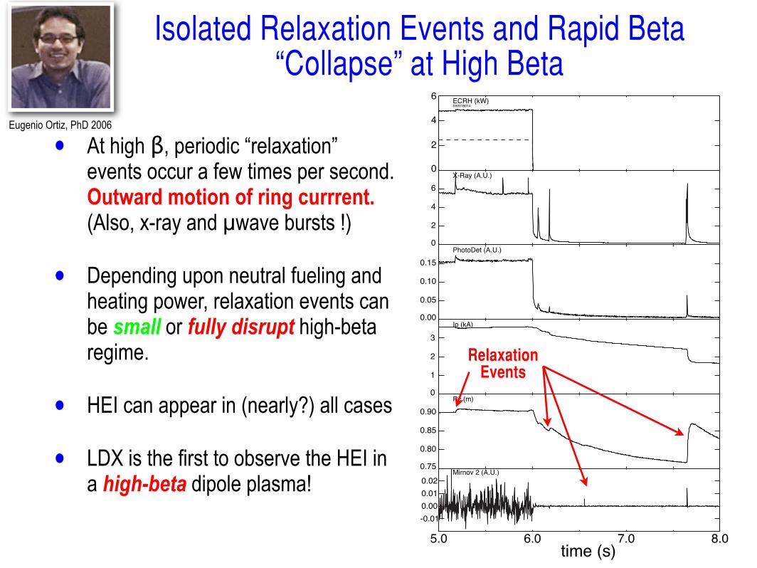
• At high β, periodic “relaxation” events occur a few times per second. Outward motion of ring currrent. (Also, x-ray and µwave bursts !)
• Depending upon neutral fueling and heating power, relaxation events can be small or fully disrupt high-beta regime.
• HEI can appear in (nearly?) all cases
• LDX is the first to observe the HEI in a high-beta dipole plasma!
0
2
4
6ECRH (kW)S50318014
0
2
4
6
X-Ray (A.U.)
0.00
0.05
0.10
0.15
PhotoDet (A.U.)
0
1
2
3
Ip (kA)
0.75
0.80
0.85
0.90
Rc (m)
5.0 6.0 7.0 8.0time (s)
-0.01
0.00
0.01
0.02Mirnov 2 (A.U.)
RelaxationEvents
Isolated Relaxation Events and Rapid Beta “Collapse” at High Beta
Eugenio Ortiz, PhD 2006

Three Types of Fast Electron Interchange Spectra
0.804 0.805 0.806 0.807 0.808
0.804 0.805 0.806 0.807 0.808time (s)
0.0
0.4
0.8
1.2
Freq
uenc
y(M
Hz)
± 20 V
ChaoticRadial
TransportIntermittent
Bursts
Edge Potential Fluctuations
100
50
0
DriftResonantEnergy(keV)
0.79 0.791 0.792 0.793 0.794
0.790 0.791 0.792 0.793 0.794time (s)
0
1
2
3
4
5
6
Freq
uenc
y(M
Hz)
± 80 V
ChaoticRadial
Transport
NonlinearFrequencySweeping
Edge Potential Fluctuations
400
200
0
DriftResonantEnergy(keV)
EEO_ICC06_INVTLK17
Minor Relaxation Burst
• < 2 % beta loss
• Short burst duration, < .5 ms
• High frequency, wide-band fluctuations
• Radially localized; detected only on adjustable
probe near peak pressure
• Large amplitude fluctuations, ± 50 V
High Density RegimeMay 13, 2005 – Shot 35Both Sources on,!Flux ~ .1 mWb
400 µsec
Top Probe
Floating Potential
Fre
qu
en
cy (
MH
z)
Vo
lts
Weak Relaxation
Burst
Low-BetaContinuous
“Disruption”
Instability behavior determined by beta and by gas fueling
history!(Hysteresis)
Eugenio Ortiz, PhD 2006

What We’ve Learned #6:
Turbulence in a Laboratory Dipole has Length Scales Dominated by the
System Size
• Power-law spectrum for convective turbulence.
• Low-frequencies (in the rotating plasma frame) characterize the dominant long wavelengths.
• Transients and phase-transitions mediated by large m = 1 rotating perturbations.

Evolution of Spectrum with Gas Fueling Rate Change
Brian GriersonMatt Worstell
Spectra
Power Spectrum
0.1 1.0 10.0 100.0 1000.0Freq (kHz)
1µ s
2µ s
3µ s
10µ s
5,40µ s
•Increased gas pressure causes change in the spectral characteristics of the fluctuations.
•Causes a trend towards power-law like spectra.
Low Density High Density
Gas Puff
Spectrogram reveals the dynamic change in floating
potential fluctuations.
9
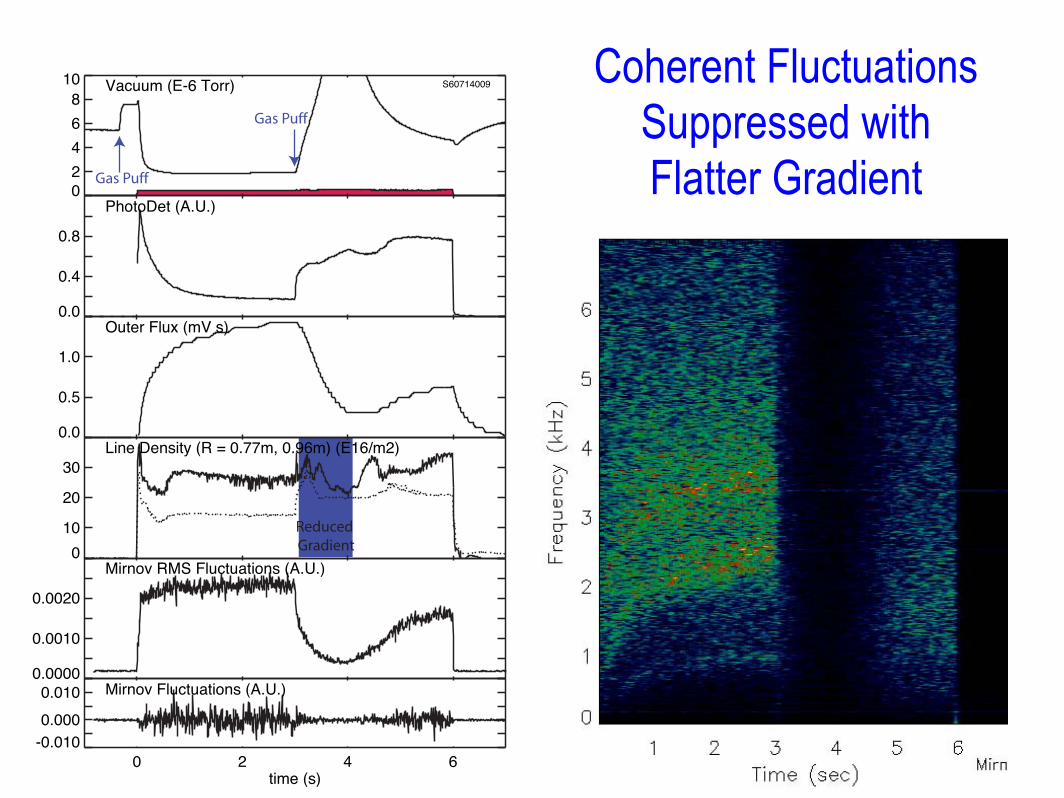
Coherent Fluctuations Suppressed with Flatter Gradient0
2
4
6
8
10Vacuum (E-6 Torr) S60714009
0.0
0.4
0.8
PhotoDet (A.U.)
0.0
0.5
1.0
Outer Flux (mV s)
0
10
20
30
Line Density (R = 0.77m, 0.96m) (E16/m2)
0.0000
0.0010
0.0020
Mirnov RMS Fluctuations (A.U.)
0 2 4 6
time (s)
-0.010
0.000
0.010 Mirnov Fluctuations (A.U.)
Gas Puff
Gas Puff
Reduced Gradient
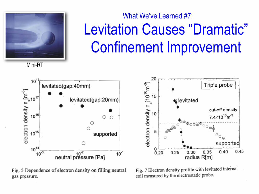
What We’ve Learned #7:
Levitation Causes “Dramatic” Confinement Improvement
Plasma production with a floating HTS coil
Mini-RT

Still Many Unanswered Questions…
• What (and why) are the particle and energy transport rates?
• How do these rates depend upon the convective turbulence?
• What are the characteristics of the convective/turbulent transport as profiles are adjusted? Why?
• Is thermal transport adiabatic in a dipole plasma?

• Dipoles provide magnetic confinement for hot plasma in nature and in the laboratory (and dipole physics may help fusion energy!)
• The dipole has a unique field structure for study of confined plasma: unmatched diagnostic access, well-characterized magnetic geometry, and fascinating (and musical) wave-particle interactions.
• Two types of global interchange instabilities excited/modeled:
‣ Hot electron interchange (fast) modes illustrate collisionless dynamics with “phase-space” mixing and “bubbles”.
‣ Centrifugal interchange (slow) modes illustrate MHD mass flows and convective mixing.
• The world’s first high-beta (β > 20%) dipole-confined plasma has been created in LDX by stabilization of the fast-electron interchange instability with programmed gas fueling.
Summary