Embed Size (px)
Citation preview
Paper ID #9907
What’s Next After Mechanics of Materials?
Dr. William E Howard, East Carolina University
William E. Howard is an Associate Professor at East Carolina University. He has fourteen years of in-dustry experience and seventeen years of academic experience at Milwaukee School of Engineering andECU.
Dr. Odis Hayden Griffin Jr., East Carolina UniversityDr. Ihab Ragai, East Carolina University
c©American Society for Engineering Education, 2014
Page 24.1371.1
What’s Next After Mechanics of Materials?
Abstract In most engineering programs, students complete a common core of mechanics courses – statics, dynamics, fluid mechanics, and mechanics of materials. The content of mechanics of materials courses is relatively consistent, including the study of stresses, strains, and deflections of components subjected to axial and shear forces and torsion and bending moments, combined stresses, and static failure criteria. Almost all mechanical engineering programs include a course in machine components, but the coverage of other solid mechanics topics varies greatly from program to program. At East Carolina University, a class titled “Solid Mechanics” has been created as a follow-on course to the mechanics of materials course for students in the mechanical engineering concentration of a general engineering program. This course was intended to include topics such as finite element analysis, non-linear structural analysis, and the analysis of plates and shells, among others. To help determine the content of the course, a random sample of 30 ABET-accredited ME program curricula was examined. The appropriate balance of theory and applications was also considered. This paper presents the topics addressed in the course, and provides details of some of the exercises and assignments in which modern computational tools are used to supplement theory and tabulated solutions. Also discussed are ways in which this approach can be used to assess several program outcomes, particularly ABET outcomes i (lifelong learning) and j (contemporary issues). Introduction At East Carolina University, mechanical engineering is a concentration option within a BS Engineering program. Since the greater breadth of a general program requires more “core” engineering classes, it is not possible to include all of the courses that are typically in the curriculum of a BS Mechanical Engineering program. When designing the curriculum for the mechanical concentration, which was introduced in 2008, the intent was to include all of the required topics that are typical of a mechanical engineering curriculum, combining some courses where necessary. The 26 credits of concentration courses are divided as:
thirteen credits of thermal-fluids classes: Thermodynamics I and II, Fluid Mechanics, and Heat and Mass Transfer,
six credits of solid mechanics classes: Solid Mechanics and Machine Design, and seven credits of technical electives.
While the credits seem to be heavily weighted toward the thermal-fluid sciences, it should be noted that all ME-concentration students are required to take mechanics of materials as a core engineering course, but do not take the combined thermal-fluid class that is required for students in the other concentrations. In the early planning stages for the ME concentration, a course in kinematics was included. In discussions among the faculty, however, we concluded that this was one area where the use of software could increase the efficiency of teaching the subject. We concluded that we could provide a reasonable coverage of kinematics, supported by exercises with motion analysis
Page 24.1371.2
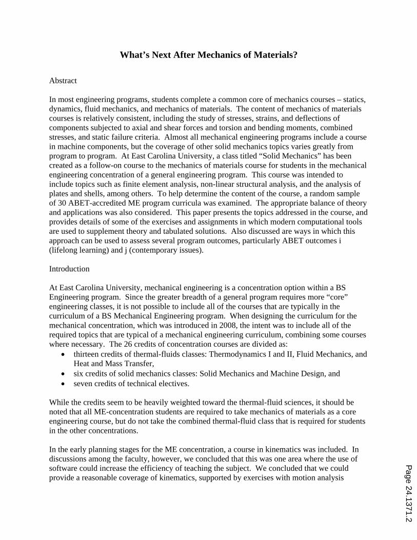
software, in much less than a full three-credit course. As a result, the machine design course was designed to consist of approximately two-thirds of components design and analysis (gears, shafts, bearings, bolts, and springs) and approximately one-third of kinematics. Fatigue failure, a major content area in a machine design course, was to be introduced in the solid mechanics course. To help determine what other topics should be included, we examined a sample of existing ME programs. Sample of Mechanical Engineering Program Curricula Jarosz and Busch-Vishniac1 examined the syllabi of nine mechanical engineering programs in detail. From these syllabi, they identified 1,392 topics that were covered in required technical courses. Of these topics, only 64 (less than 5%) were included in five or more of the nine programs. A conclusion of this study was that there is greater variability in ME curricula than may be expected, and that programs may be including “legacy” topics that are no longer critical and may be limiting the inclusion of newer, more relevant topics. In our study, we did not analyze topics at syllabus-level detail, but instead looked at course offerings in the solid mechanics area. The website of ABET, Inc.2 lists 301 accredited 4-year mechanical engineering programs. For our sample, we examined 30 programs, selecting every 10th program from an alphabetical list of the accredited programs. By looking at each program’s curriculum and course descriptions as published on the institution’s website, we noted whether that program had required classes in machine components, machine kinematics, vibrations/ dynamic systems, or finite element analysis. We also looked for any other required class in solid mechanics. The findings of this study are summarized in Table 1.
Table 1 Required Classes in ME Program Sample
Course Number of Programs with
Required Class % of Sample
Machine Components 26* 87 Machine Kinematics 16* ** 53 Vibrations/Dynamic Systems 17 57 Finite Element Analysis 7 ** 23 Other Solid Mechanics Courses 6 20
* Includes one combined class of kinematics/components ** Includes one combined class of kinematics/finite element analysis Not surprisingly, a course in machine components is included in most ME programs. The few programs without a required components class were programs with different options or concentrations. In these programs, a class in components was usually required for students choosing a mechanical design option, but not for all ME students. Approximately half of the programs have kinematics or vibrations courses. It should be noted that almost all programs include a controls course, which is not usually considered to be a solid mechanics subject. The 17 programs tallied in Table 1 include a separate course in vibrations or dynamic systems in addition to the controls class.
Page 24.1371.3
While finite element analysis has become a mainstream tool for mechanical design and analysis, only about a quarter of the programs have a required class in FEA. This result seems consistent with recent publications detailing the use of FEA throughout the curriculum rather than coverage of the topic in a single course. Brinson et al.3, Zhao4 and Chaphalkar and Blekhman5 report on the use of FEA in basic (statics and mechanics of materials) mechanics courses. Watkins6 presents results from an FEA class that has de-emphasized theory and problem solving with a general tool (Excel or MATLAB) and increased usage of a commercial FEA program. Papadopoulos, Papadopoulos, and Prantil7 lay out a strategy for incorporating FEA throughout the curriculum, without rigorous coverage of the theory. While there is naturally resistance to introducing FEA without the theoretical background, Papadopoulos et al. argue that this resistance needs to be reconsidered:
We clearly don’t apply this criterion consistently, since most of us don’t know how to design the circuits or write the software for our calculators. Many of us can’t even derive the inverse Laplace transforms given in tables. Perhaps this argument is a legacy of the traditional top-down, analysis-first approach with which engineering, and mechanics in particular, have been taught for decades.
The six programs in the sample that have another required solid mechanics class include a wide variety of topics in that class, including:
combined stresses failure criteria (static and fatigue) multiaxial stress states (plates and shells) pressure vessels statically indeterminate structures torsion of nonsymmetric members curved beams energy methods structural stability stress concentrations
The titles of these classes include “Mechanical Design and Analysis”, “Applied Strength of Materials”, and similar names. The list of topics above is a mix of those found in basic mechanics of materials texts and more advanced textbooks. Several texts exist with the title “Advanced Mechanics of Materials” or “Advanced Strength of Materials,” including J. P. Den Hartog’s classic 1952 work8. In the introduction to that text, the author explains his goal to bridge the gap between elementary mechanics of materials texts and the advanced works of Stephen Timoshenko. The table of contents for Den Hartog’s book includes chapters on torsion, beams on elastic foundations, buckling, energy methods, membrane stresses in shells, bending stresses in plates, and 2-D elasticity. The treatment of these topics is rigorous; the text was intended for two semesters of class work, one at the undergraduate level and one at the graduate level. Of course, in 1952 students did not have access to the power of personal computers and analysis software. This brings us back to the question faced when discussing the use of FEA: how much
Page 24.1371.4
of the rigorous theory is required for a practicing engineer, now that the calculations can be done by software? As we have defined and refined the curriculum at East Carolina University, we have attempted to find a reasonable balance between theory and application. Solid Mechanics Course Content With the content of the new machine design class and the existing mechanics of materials course established, we focused on the topics that we wanted to include in the solid mechanics course. As mentioned earlier, an introduction to fatigue failure was to be included, so that the machine design class could move into components very early in the class (after a short review of static and fatigue failure criteria). In choosing the topics for the solid mechanics course, we tried to answer the question:
What topics not covered in the mechanics of materials or machine design classes (or not covered in sufficient depth) will be of the greatest value to entry-level mechanical engineers?
The syllabus for the solid mechanics course includes 25 class sessions (each 75 minutes long), not including tests. In Spring 2013, the sessions were allocated as follows:
Review of mechanics of materials concepts of stresses and deflections (one session). Statically indeterminate structures (three sessions). Statically indeterminate structures
subjected to axial loading and temperature changes are introduced in mechanics of materials, but time does not permit coverage of statically indeterminate beams. Analysis of a frame structure utilizes both hand calculations and finite element analysis.
Static failure criteria – ductile and brittle materials (four sessions). This is another topic that is introduced in mechanics of materials but only briefly and only for ductile materials.
Fatigue failure criteria (four sessions). Energy methods (two sessions). The emphasis here is on impact loading, and having the
students develop a feel for the magnitudes of impact loads relative to static loading. Basic theory of finite element analysis (four sessions). Beginning with truss elements,
students learn how to transform stresses and strains in a 2-D coordinate system, assemble a system stiffness matrix, apply boundary conditions, and solve for displacements and reaction forces. Calculations are made with spreadsheets. Simple beam elements are then introduced, as an application of energy methods. Our goal with these sessions is to provide students with a basic understanding of the method of finite element analysis, without delving into the theory of more complex element equations.
Non-linear analysis (two sessions). Although only a brief introduction, students should realize that all of the calculations made in their mechanics of materials courses are based on linear approximations of non-linear problems.
Plates and shells (one session). Although one session is certainly not enough time to go into any depth on this topic, a reasonable introduction can be made by presenting the nomenclature of plates and shells and then presenting tabulated solutions from a reference such as Roark’s Formulas for Stress and Strain9. An assignment has the students analyze a flat circular plate with varying pressure loading in order to see the difference between linear and non-linear solutions. This exercise is also used to assess the program outcome related to lifelong learning.
Page 24.1371.5
Vibrations (two sessions). A single degree-of-freedom system is analyzed using a numerical approach (Duhamel’s integral). Students compare the response of the system when subjected to various forcing functions.
Thin- and thick-wall pressure vessels (two sessions). Cylindrical and spherical thin-wall pressure vessels are introduced in mechanics of materials, and represent the first examples that students see of structures subjected to biaxial stress states. Similarly, thick-wall vessels can serve as an example of a 3-D stress state.
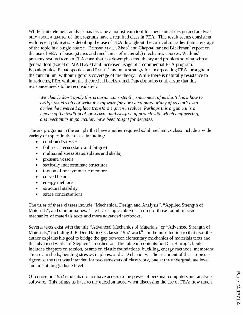
Some specific example problems and assignments that illustrate the incorporation of software tools and/or comparisons to tabulated solutions are discussed in the following sections. Statically Indeterminate Structures: We begin this section with simple problems involving single beams from textbook of our mechanics of materials class, Hibbeler’s Mechanics of Materials.10 We then introduce a more complex problem – the three-member beam structure illustrated in Figure 1. Free body diagrams of the members are shown in Figure 2. The members are square steel tubes.
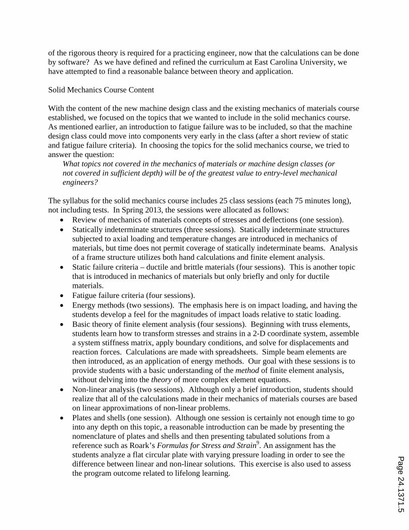
Figure 1 Statically Inteterminate Frame Figure 2 Free Body Diagrams of Frame Members Although the problem is much more complex than the single-beam examples, we point out that the solution method is the same, and that all of the 12 unknown quantities can be found with statics equations and the tabulated deflections of simple beams. From statics, nine equilibrium equations can be written. Three other equations come from compatibility conditions – the slopes of AB and BC must match at joint B, and the slopes of BC and CD must match at joint C. Also, the difference of the horizontal displacements at B and C must equal the axial deflection of BC (or zero, if the axial deflection is ignored, which can be the basis of class discussion). The solution of the equations by matrix algebra in a spreadsheet allows variations of the problems to be easily studied. For example, how does the solution change if the bending stiffness of BC is changed to be much less or much greater than the stiffness of the horizontal members? We then present a more complex frame, shown in Figure 3, as an exercise to be solved with FEA. We try to emphasize that the solution method of the FEA software is similar to the hand-calculation solution of the simpler frame. We use SolidWorks Simulation as the FEA tool. Students are generally proficient with SolidWorks after their freshman graphics course, and the students have access to SolidWorks, including the FEA add-in, on their personal computers
Page 24.1371.6
through a network license. Also, two introductory FEA exercises are included in the lab portion of the mechanics of materials course.
Figure 3 Frame Problem Solved with FEA
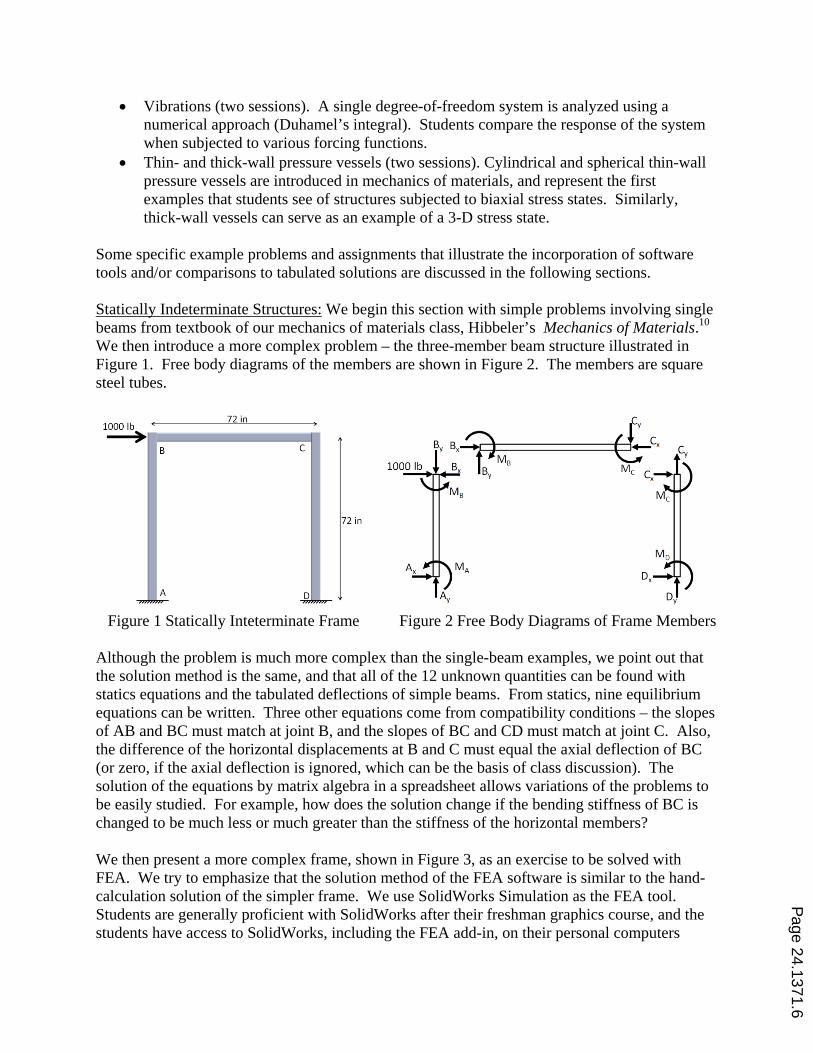
One important lesson from this example is that solid elements are not always the best choice for an analysis. We have noted over the years that because students model in a 3-D environment, they tend to use solid elements for analyses without considering other element types. In this frame, the thin walls of the structural members would require a very large number of elements to model adequately with solid elements, while only a few beam elements are necessary to produce accurate results. Non-Linear Analysis Introduction: As an introduction to non-linear analysis, we present a problem from statics – a weight supported by two cables, as shown in Figure 4.
Figure 4 Introductory Problem for Non-Linear Analysis
We remind the students that when a member is subjected to an axial load, then its length will change. Therefore, the geometry shown applies to either the geometry before the load is applied, or to the final geometry after the load is applied. If we assume that the geometry applies before the load is applied, then we can calculate the load in each wire (84.9 and 72.1 pounds for cables A and B, respectively), and then the amount that each wire stretches. Assuming that the wires are steel, with diameters of 0.10 inches, then each wire stretches less than 0.03 inches. Therefore, assuming that the original and deflected geometries are identical seems to be a reasonable assumption.
Page 24.1371.7
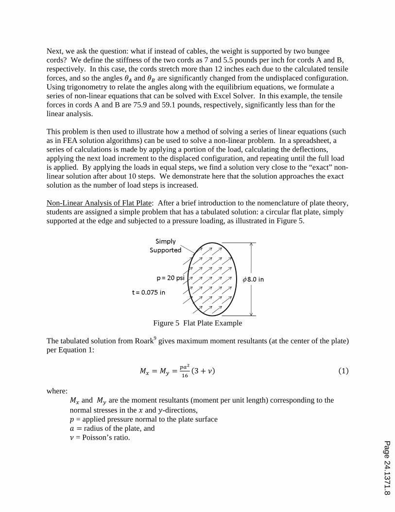
Next, we ask the question: what if instead of cables, the weight is supported by two bungee cords? We define the stiffness of the two cords as 7 and 5.5 pounds per inch for cords A and B, respectively. In this case, the cords stretch more than 12 inches each due to the calculated tensile forces, and so the angles and are significantly changed from the undisplaced configuration. Using trigonometry to relate the angles along with the equilibrium equations, we formulate a series of non-linear equations that can be solved with Excel Solver. In this example, the tensile forces in cords A and B are 75.9 and 59.1 pounds, respectively, significantly less than for the linear analysis. This problem is then used to illustrate how a method of solving a series of linear equations (such as in FEA solution algorithms) can be used to solve a non-linear problem. In a spreadsheet, a series of calculations is made by applying a portion of the load, calculating the deflections, applying the next load increment to the displaced configuration, and repeating until the full load is applied. By applying the loads in equal steps, we find a solution very close to the “exact” non-linear solution after about 10 steps. We demonstrate here that the solution approaches the exact solution as the number of load steps is increased. Non-Linear Analysis of Flat Plate: After a brief introduction to the nomenclature of plate theory, students are assigned a simple problem that has a tabulated solution: a circular flat plate, simply supported at the edge and subjected to a pressure loading, as illustrated in Figure 5.
Figure 5 Flat Plate Example
The tabulated solution from Roark9 gives maximum moment resultants (at the center of the plate) per Equation 1:
3 1
where:
and are the moment resultants (moment per unit length) corresponding to the normal stresses in the and -directions,
= applied pressure normal to the plate surface radius of the plate, and
= Poisson’s ratio.
Page 24.1371.8
Since the two moments are equal, the von-Mises equivalent stress is the same as the normal stress in either direction:
20 lbin 4in
163.32 66.40
in ∙ lbin
2
6 6 66.40 in ∙ lbin0.075in
70,800psi 3
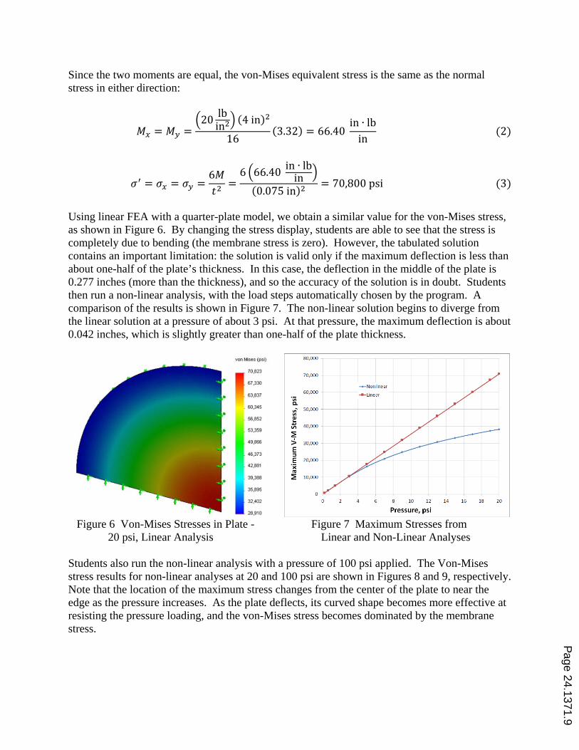
Using linear FEA with a quarter-plate model, we obtain a similar value for the von-Mises stress, as shown in Figure 6. By changing the stress display, students are able to see that the stress is completely due to bending (the membrane stress is zero). However, the tabulated solution contains an important limitation: the solution is valid only if the maximum deflection is less than about one-half of the plate’s thickness. In this case, the deflection in the middle of the plate is 0.277 inches (more than the thickness), and so the accuracy of the solution is in doubt. Students then run a non-linear analysis, with the load steps automatically chosen by the program. A comparison of the results is shown in Figure 7. The non-linear solution begins to diverge from the linear solution at a pressure of about 3 psi. At that pressure, the maximum deflection is about 0.042 inches, which is slightly greater than one-half of the plate thickness.
Figure 6 Von-Mises Stresses in Plate - Figure 7 Maximum Stresses from 20 psi, Linear Analysis Linear and Non-Linear Analyses Students also run the non-linear analysis with a pressure of 100 psi applied. The Von-Mises stress results for non-linear analyses at 20 and 100 psi are shown in Figures 8 and 9, respectively. Note that the location of the maximum stress changes from the center of the plate to near the edge as the pressure increases. As the plate deflects, its curved shape becomes more effective at resisting the pressure loading, and the von-Mises stress becomes dominated by the membrane stress.
Page 24.1371.9
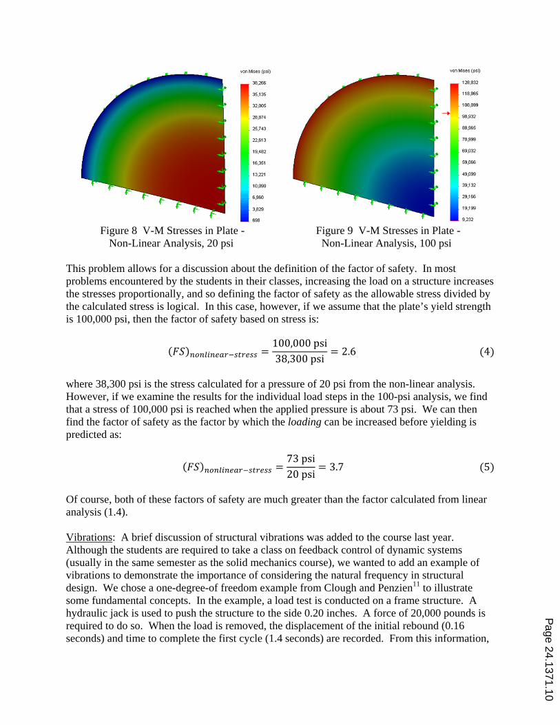
Figure 8 V-M Stresses in Plate - Figure 9 V-M Stresses in Plate -
Non-Linear Analysis, 20 psi Non-Linear Analysis, 100 psi
This problem allows for a discussion about the definition of the factor of safety. In most problems encountered by the students in their classes, increasing the load on a structure increases the stresses proportionally, and so defining the factor of safety as the allowable stress divided by the calculated stress is logical. In this case, however, if we assume that the plate’s yield strength is 100,000 psi, then the factor of safety based on stress is:
100,000psi38,300psi
2.6 4
where 38,300 psi is the stress calculated for a pressure of 20 psi from the non-linear analysis. However, if we examine the results for the individual load steps in the 100-psi analysis, we find that a stress of 100,000 psi is reached when the applied pressure is about 73 psi. We can then find the factor of safety as the factor by which the loading can be increased before yielding is predicted as:
73psi20psi
3.7 5
Of course, both of these factors of safety are much greater than the factor calculated from linear analysis (1.4). Vibrations: A brief discussion of structural vibrations was added to the course last year. Although the students are required to take a class on feedback control of dynamic systems (usually in the same semester as the solid mechanics course), we wanted to add an example of vibrations to demonstrate the importance of considering the natural frequency in structural design. We chose a one-degree-of freedom example from Clough and Penzien11 to illustrate some fundamental concepts. In the example, a load test is conducted on a frame structure. A hydraulic jack is used to push the structure to the side 0.20 inches. A force of 20,000 pounds is required to do so. When the load is removed, the displacement of the initial rebound (0.16 seconds) and time to complete the first cycle (1.4 seconds) are recorded. From this information,
Page 24.1371.10
we calculate the stiffness, damping ratio, effective mass, and damped and undamped natural frequencies of the system. We also plot the displacement versus time for subsequent cycles. We then move to problems of forced vibrations. Using the example discussed above, we consider simple forcing functions for which tabulated solutions exist. We then present a method for calculating the response to any forcing function, Duhamel’s integral11. The displacement at any time is found by evaluating this integral from time = 0 to time = :
1sin 6
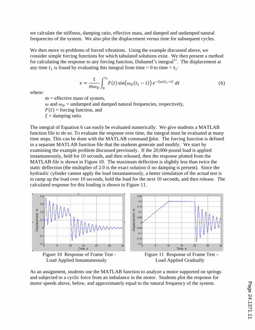
where: m = effective mass of system, and = undamped and damped natural frequencies, respectively, = forcing function, and = damping ratio. The integral of Equation 6 can easily be evaluated numerically. We give students a MATLAB function file to do so. To evaluate the response over time, the integral must be evaluated at many time steps. This can be done with the MATLAB command fplot. The forcing function is defined in a separate MATLAB function file that the students generate and modify. We start by examining the example problem discussed previously. If the 20,000-pound load is applied instantaneously, held for 10 seconds, and then released, then the response plotted from the MATLAB file is shown in Figure 10. The maximum deflection is slightly less than twice the static deflection (the multiplier of 2.0 is the exact solution if no damping is present). Since the hydraulic cylinder cannot apply the load instantaneously, a better simulation of the actual test is to ramp up the load over 10 seconds, hold the load for the next 10 seconds, and then release. The calculated response for this loading is shown in Figure 11.
Figure 10 Response of Frame Test - Figure 11 Response of Frame Test – Load Applied Instantaneously Load Applied Gradually As an assignment, students use the MATLAB function to analyze a motor supported on springs and subjected to a cyclic force from an imbalance in the motor. Students plot the response for motor speeds above, below, and approximately equal to the natural frequency of the system.
Page 24.1371.11
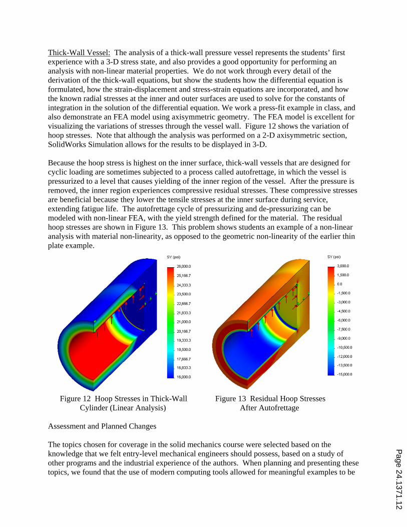
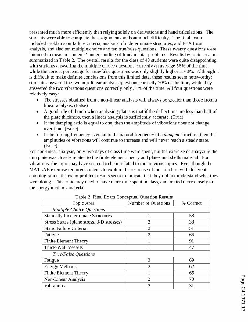
Thick-Wall Vessel: The analysis of a thick-wall pressure vessel represents the students’ first experience with a 3-D stress state, and also provides a good opportunity for performing an analysis with non-linear material properties. We do not work through every detail of the derivation of the thick-wall equations, but show the students how the differential equation is formulated, how the strain-displacement and stress-strain equations are incorporated, and how the known radial stresses at the inner and outer surfaces are used to solve for the constants of integration in the solution of the differential equation. We work a press-fit example in class, and also demonstrate an FEA model using axisymmetric geometry. The FEA model is excellent for visualizing the variations of stresses through the vessel wall. Figure 12 shows the variation of hoop stresses. Note that although the analysis was performed on a 2-D axisymmetric section, SolidWorks Simulation allows for the results to be displayed in 3-D. Because the hoop stress is highest on the inner surface, thick-wall vessels that are designed for cyclic loading are sometimes subjected to a process called autofrettage, in which the vessel is pressurized to a level that causes yielding of the inner region of the vessel. After the pressure is removed, the inner region experiences compressive residual stresses. These compressive stresses are beneficial because they lower the tensile stresses at the inner surface during service, extending fatigue life. The autofrettage cycle of pressurizing and de-pressurizing can be modeled with non-linear FEA, with the yield strength defined for the material. The residual hoop stresses are shown in Figure 13. This problem shows students an example of a non-linear analysis with material non-linearity, as opposed to the geometric non-linearity of the earlier thin plate example.
Figure 12 Hoop Stresses in Thick-Wall Figure 13 Residual Hoop Stresses Cylinder (Linear Analysis) After Autofrettage Assessment and Planned Changes The topics chosen for coverage in the solid mechanics course were selected based on the knowledge that we felt entry-level mechanical engineers should possess, based on a study of other programs and the industrial experience of the authors. When planning and presenting these topics, we found that the use of modern computing tools allowed for meaningful examples to be
Page 24.1371.12
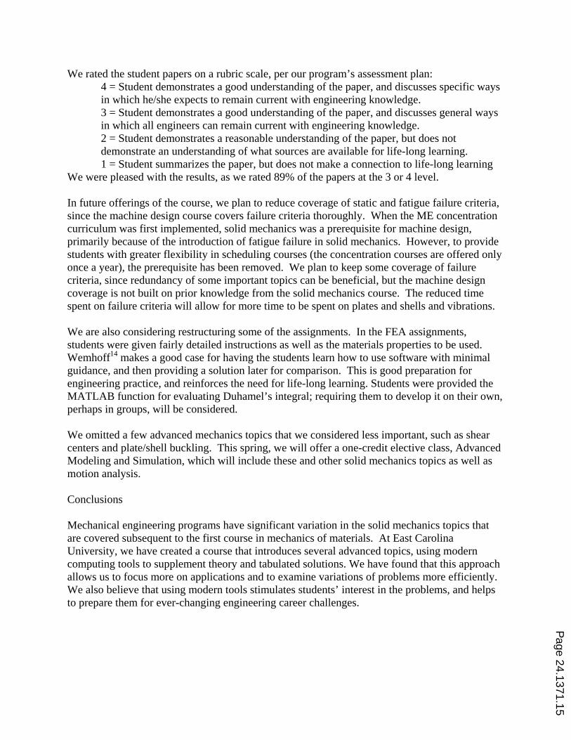
presented much more efficiently than relying solely on derivations and hand calculations. The students were able to complete the assignments without much difficulty. The final exam included problems on failure criteria, analysis of indeterminate structures, and FEA truss analysis, and also ten multiple choice and ten true/false questions. These twenty questions were intended to measure students’ understanding of fundamental problems. Results by topic area are summarized in Table 2. The overall results for the class of 43 students were quite disappointing, with students answering the multiple choice questions correctly an average 56% of the time, while the correct percentage for true/false questions was only slightly higher at 60%. Although it is difficult to make definite conclusions from this limited data, these results seem noteworthy: students answered the two non-linear analysis questions correctly 70% of the time, while they answered the two vibrations questions correctly only 31% of the time. All four questions were relatively easy:
The stresses obtained from a non-linear analysis will always be greater than those from a linear analysis. (False)
A good rule of thumb when analyzing plates is that if the deflections are less than half of the plate thickness, then a linear analysis is sufficiently accurate. (True)
If the damping ratio is equal to one, then the amplitude of vibrations does not change over time. (False)
If the forcing frequency is equal to the natural frequency of a damped structure, then the amplitudes of vibrations will continue to increase and will never reach a steady state. (False)
For non-linear analysis, only two days of class time were spent, but the exercise of analyzing the thin plate was closely related to the finite element theory and plates and shells material. For vibrations, the topic may have seemed to be unrelated to the previous topics. Even though the MATLAB exercise required students to explore the response of the structure with different damping ratios, the exam problem results seem to indicate that they did not understand what they were doing. This topic may need to have more time spent in class, and be tied more closely to the energy methods material.
Table 2 Final Exam Conceptual Question Results Topic Area Number of Questions % Correct
Multiple Choice Questions Statically Indeterminate Structures 1 58 Stress States (plane stress, 3-D stresses) 2 38 Static Failure Criteria 3 51 Fatigue 2 66 Finite Element Theory 1 91 Thick-Wall Vessels 1 47 True/False Questions Fatigue 3 69 Energy Methods 2 62 Finite Element Theory 1 65 Non-Linear Analysis 2 70 Vibrations 2 31
Page 24.1371.13

Student surveys were uniformly positive, as shown in Table 3, but the questions were not detailed enough to provide meaningful results. Also, we find that students often over-estimate their own achievement of the objectives. Better assessment instruments are being planned for the next offering of the course, with periodic surveys and quizzes to determine the effectiveness of the teaching methods In particular, the number of conceptual questions for the final exam will be expanded to include more questions for reach topic, and students will be asked to rate the value of the exercises.
Table 3 Student Survey Results (39 Students)
Course Objective % of Students Choosing 4 or 5 (“Agree” or “Strongly Agree”)
on a 5-Point Scale I am able to combine stresses from various loadings on a structure and determine principal stresses.
97
I am able to select and apply appropriate static failure criteria for ductile and brittle materials.
97
I am able to apply failure criteria for fatigue loading. 95
I am able to analyze statically indeterminate structures.
92
I am able to find stresses resulting from impact loading.
90
I am able to explain the basic principles of finite element analysis.
79
The use of modern computing tools allows for the assessment of several ABET outcomes. Outcome k (use of techniques and modern tools of engineering) can be easily assessed in this course, although we did not do so because our assessment plan calls for assessment of outcome k in several other courses. We did assess outcomes i (life-long learning) and j (contemporary issues) in this class. In both cases, we asked students to read an article from an Internet source and write a reflection summarizing the article and relating it to their careers. We have found Machine Design magazine’s website12 in particular to be an excellent source for this type of article. For outcome i, we found a white paper on non-linear analysis from SolidWorks Corporation13 to be appropriate. After completing the non-linear analysis assignment, we gave the students the assignment as follows:
In this assignment, we used tabulated results that have been available for many decades along with non-linear software that was not readily available to engineering graduates of only a few years ago. Without a doubt, you will need to keep learning throughout your career. Besides formal classes, trade magazines and commercial publications can be excellent resources for additional learning. SolidWorks has published a paper titled “Understanding Nonlinear Analysis” directed toward design engineers who may be unaware of why and when nonlinear analysis may be recommended. This paper is posted to Blackboard. Read it and write a one-page (single-spaced, 12-point font) paper summarizing the paper and your thoughts of how you expect to continue learning throughout your career.
Page 24.1371.14
We rated the student papers on a rubric scale, per our program’s assessment plan: 4 = Student demonstrates a good understanding of the paper, and discusses specific ways in which he/she expects to remain current with engineering knowledge. 3 = Student demonstrates a good understanding of the paper, and discusses general ways in which all engineers can remain current with engineering knowledge. 2 = Student demonstrates a reasonable understanding of the paper, but does not demonstrate an understanding of what sources are available for life-long learning. 1 = Student summarizes the paper, but does not make a connection to life-long learning
We were pleased with the results, as we rated 89% of the papers at the 3 or 4 level. In future offerings of the course, we plan to reduce coverage of static and fatigue failure criteria, since the machine design course covers failure criteria thoroughly. When the ME concentration curriculum was first implemented, solid mechanics was a prerequisite for machine design, primarily because of the introduction of fatigue failure in solid mechanics. However, to provide students with greater flexibility in scheduling courses (the concentration courses are offered only once a year), the prerequisite has been removed. We plan to keep some coverage of failure criteria, since redundancy of some important topics can be beneficial, but the machine design coverage is not built on prior knowledge from the solid mechanics course. The reduced time spent on failure criteria will allow for more time to be spent on plates and shells and vibrations. We are also considering restructuring some of the assignments. In the FEA assignments, students were given fairly detailed instructions as well as the materials properties to be used. Wemhoff14 makes a good case for having the students learn how to use software with minimal guidance, and then providing a solution later for comparison. This is good preparation for engineering practice, and reinforces the need for life-long learning. Students were provided the MATLAB function for evaluating Duhamel’s integral; requiring them to develop it on their own, perhaps in groups, will be considered. We omitted a few advanced mechanics topics that we considered less important, such as shear centers and plate/shell buckling. This spring, we will offer a one-credit elective class, Advanced Modeling and Simulation, which will include these and other solid mechanics topics as well as motion analysis. Conclusions Mechanical engineering programs have significant variation in the solid mechanics topics that are covered subsequent to the first course in mechanics of materials. At East Carolina University, we have created a course that introduces several advanced topics, using modern computing tools to supplement theory and tabulated solutions. We have found that this approach allows us to focus more on applications and to examine variations of problems more efficiently. We also believe that using modern tools stimulates students’ interest in the problems, and helps to prepare them for ever-changing engineering career challenges.
Page 24.1371.15
References
1. Jarosz, J., and Busch-Vishniac, I., “A Topical Analysis of Mechanical Engineering Curricula”, Journal of Engineering Education, vol. 95, no. 3, July, 2006.
2. Accredited Program Search, ABET, Inc.: http://main.abet.org/aps/Accreditedprogramsearch.aspx
3. Brinson, L., Belytschko, T., Moran, B., and Black, T., “Design and Computational Methods in Basic
Mechanics Courses”, Journal of Engineering Education, vol. 86, no. 2, April, 1997.
4. Zhao, J. “Teaching Finite Element Analysis as a Solution Method for Truss Problems in Statics”, Proceedings of the ASEE Annual Conference & Exposition, Salt Lake City, UT, June 2004
5. Chaphalkar, P. and D. Blekhman. “Introducing Finite Element Analysis in the First Course of Statics and Solid Mechanics”, Proceedings of the ASEE Annual Conference & Exposition, Honolulu, HI, June 2007.
6. Watkins, G., “Theory and Commercial Software - Finding the Balance in a Finite Elements Course”,
Proceedings of the ASEE Annual Conference & Exposition, Atlanta, GA, June 2013.
7. Papadopoulos, J., Papadopoulos, C. and Prantil, V., A Philosophy of Integrating FEA Practice throughout the Undergraduate CE/ME Curriculum”, Proceedings of the ASEE Annual Conference and Exposition, Vancouver, Canada, June, 2011.
8. Den Hartog, J., Advanced Strength of Materials, Dover Publications, 1987.
9. Roark, R., Formulas for Stress and Strain, 5th Edition, McGraw-Hill, 1975.
10. Hibbeler, R., Mechanics of Materials, 8th Edition, Prentice Hall, 2010.
11. Clough, R, and Penzien, J., Dynamics of Structures, 2nd Edition, McGraw-Hill, 1993.
12. Machine Design Magazine Engineering Essentials: http://machinedesign.com/engineering-essentials-1
13. SolidWorks White Papers Library: http://www.solidworks.com/sw/3d-cad-whitepapers.htm
14. Wemhoff, A., “Exercises For Students to Learn The Proper Application of Analytical Commercial Engineering Software”, Dr. Aaron P. Wemhoff, Proceedings of the ASEE Annual Conference and Exposition, San Antonio, TX, June, 2012.
Page 24.1371.16


![Mechanics] MIT Materials Science and Engineering - Mechanics of Materials (Fall 1999)](https://img.pdfslide.us/doc/110x75/552532ce5503462a6f8b4744/mechanics-mit-materials-science-and-engineering-mechanics-of-materials-fall-1999.jpg)