Embed Size (px)
Citation preview

Shear and Principal StressesShear and Principal Stresses
A lecture assembled for the course onStatics and Strength of Materials
by Jason E. Charalambides PhD, PE, M.ASCE, AIA, ENV_SP
Data composed exclusively by author(only for educational purposes)
2
What is Shear Stress?

3
Shear as a form of StressShear as a form of Stress
Load translated to Stress Shear is a stress that can be applied to a
Structural element, just like axial stress orflexural stress.
It is however particularly different in the wayit affects the structural elements and how itspresence alters the end result of the stresspatterns that we have addressed so far.
Where axial load will tend to elongate orcontract the length of an element, Flexuralstress will tend to bend the element, Shearwill tend to tear an element in a way that theopposite surfaces of a section will slidetoward opposite directions.

5
Shear as a form of StressShear as a form of Stress
Load translated to Stress It is a very common misconception that Shear
occurs perpendicular to the axis of anelement. Although in general this is the mostcommon case, Shear actually can occur in alldirections.
In the figure we can see a standard sizetimber element subjected to shear. The useof a horizontal beam was chosen in order toallow the reader to better visualize the effect.
Shear occurs actually both along the lengthof the beam, producing a longitudinal slipeffect and transversal to the beam causing atransversal tear.
6
Shear as a form of StressShear as a form of Stress
Load translated to Stress In the case on top, due to flexure, the beam
tends to develop compression on top andtension on the bottom. As a reaction to thetension caused by the deflection, the lowerportion of the beam will tend to contract.
On the upper portion of the element, due tothe compression experienced, the elementwill seek to relieve that stress by expanding.
On the bottom figure, the middle portiondrops due to the load applied on it, whilst theedge portions tend to oppose the loadthrough the supports. So the middle elementtends to slip transversally.

7
Shear as a form of StressShear as a form of Stress
Load translated to Stress Naturally neither of the two
conditions are anticipated to begoverning, but instead acombination of the two willproduce a resultant state.
By measuring the stresses atPoint C of the above figure, atmid-depth of the given element,a result of forces similar to thediagram can be anticipated.

10
Shear as a form of StressShear as a form of Stress
Load translated to Stress There is a number of different types of shear, such as the shear effects on
soil mechanics, fluid shear, etc. For the scope pertaining to what will beused by a building professional focusing on Structures, the applicable type ofshear stress is the formula developed by D.I. Zhuravskii in the 19th century:
where Q is the statical moment of area, t is the thickness of the element actingperpendicular to the direction of the shear, and I is the moment of inertia of thesection. The statical moment of area is a newly introduced quality in this text. Itis a measurement of area multiplied by distance of the centroid of that area tothe Neutral Axis:
where d is the distance of the centroid of that Area from the N/A.
For a rectangular section, the maximum value of shear stress can bedetermined by :
τ=V⋅QI⋅t
Q=A⋅d
τ max=1.5⋅Vbw⋅h
11
Shear as a form of StressShear as a form of Stress
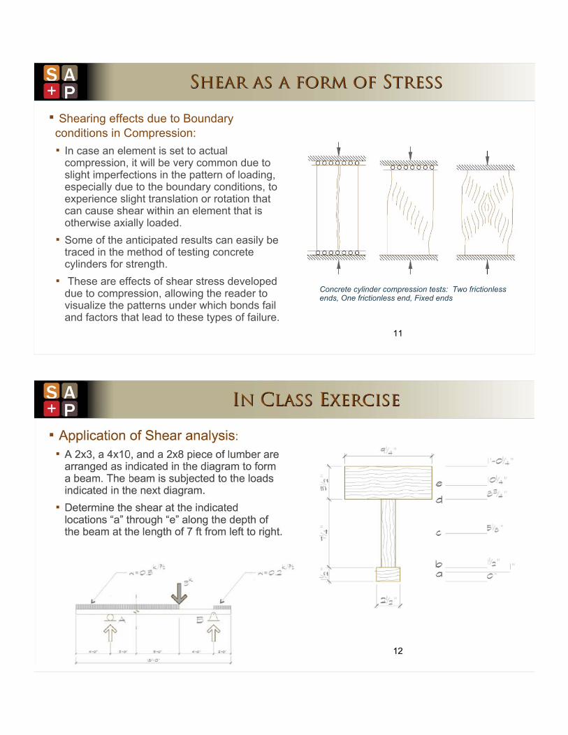
Shearing effects due to Boundaryconditions in Compression: In case an element is set to actual
compression, it will be very common due toslight imperfections in the pattern of loading,especially due to the boundary conditions, toexperience slight translation or rotation thatcan cause shear within an element that isotherwise axially loaded.
Some of the anticipated results can easily betraced in the method of testing concretecylinders for strength.
These are effects of shear stress developeddue to compression, allowing the reader tovisualize the patterns under which bonds failand factors that lead to these types of failure.
Concrete cylinder compression tests: Two frictionlessends, One frictionless end, Fixed ends

Incremental Shear Stress
A 2x3, a 4x10, and a 2x8 pieces of lumber arearranged as indicated in the diagram to form abeam. The beam is subjected to the loadsindicated in the next diagram.
•Determine the Shear stresses at the locationsindicated below.
Beam's Length Lbeam 18ft:=
Support Locations: xRA 4ft:= xRB 16ft:=
Other UDLs: w1 .3kipft
:= w2 0.2kipft
:=
xLw1 0ft:= xRw1 12ft:=Beginning and end locations of uniformly distributed loads:
Resultant locations ofuniformly distributed loads:
Resw1 xLw1xRw1 xLw1−
2+:= Resw1 6 ft=
xLw2 xRB:= xRw2 Lbeam:=
Resw2 xLw2xRw2 xLw2−
2+:= Resw2 17 ft=
Point Loads: P1 3kip:= P2 0.kip:= P3 0.kip:= Location Pt.Loads: xp1 xRw1:= xp2 0ft:= xp3 0ft:=
Solution:1) Determining the total load and the reactions:
Loadtot w1 xRw1 xLw1−( )⋅ w2 xRw2 xLw2−( )⋅ + P1+ P2+ P3+:= Loadtot 7 kip⋅=
Solving for reactions using sum of moments and sum of forces:
RBw1 xRw1 xLw1−( )⋅ Resw1 xRA−( )⋅ w2 xRw2 xLw2−( )⋅ Resw2 xRA−( )⋅+ P1 xp1 xRA−( )⋅+ P2 xp2 xRA−( )⋅+ P3 xp3 xRA−(⋅+−
xRB xRA−:=
Generating Diagrams: RB 3.033− kip⋅= RA Loadtot RB+( )−:= RA 3.967− kip⋅=
0 2 4 6 8 10 12 14 16 183−
2−
1−
0
1
2
3Shear Diagram
V x( )
kip
x ft 1−⋅
RB 3.033− kip=
RA RB+ 7− kip=
Vu if Vmin Vmax≥ Vmin, Vmax, ( ):= Vu 2.77 kip⋅=

• Calculate the shear stress "τ" at the points indicated as "a" through "e"on the location of the cut sign on the diagram. (for the sake of argumentone extra location at 24ft is added to the one required at 7ft along thelength of the beam)• Construct a diagram of the shear stress "τ" along the section of thebeam.
V 7ft( ) 1866.667 lbf⋅=
V 14ft( ) 2633.333− lbf⋅=
Length 2x8 L28 7.25in:=
Width 2x8 W28 1.5in:=
Area 2x8 A28 W28 L28⋅ 10.875 in2⋅=:=
Length 2x3 L23 2.5in:=
Width 2x3 W23 1.5in:=
Area 2x4 A23 W23 L23⋅ 3.75 in2⋅=:=
Length 4x10 L410 9.25in:=
Width 4x10 W410 3.5in:=
Area 4x10 A410 W410 L410⋅ 32.375 in2⋅=:=
Solution:1) Calculating the moment of inertia of the element:a) Starting by calculating the center of gravity of the composed element:Taking the bottom extreme fiber as reference:
Cg0.5 W23⋅ A23( )⋅ W23 0.5 L28⋅+( ) A28( )⋅ + W23 L28+ 0.5 W410⋅+( ) A410( )⋅ +
A28( ) A23( )+ A410( )+:= Cg 8.48 in⋅=
b) Calculating the moment of inertia of each individual portion:
d1 CgW23
2−:= d1 7.73 in⋅= I1
L23 W233
⋅
12A23 d1
2⋅+:= I1 224.68 in4
⋅=
d2 CgL28
2W23+
−:= d2 3.35 in⋅= I2W28 L28
3⋅
12A28 d2
2⋅+:= I2 169.93 in4
⋅=
d3W410
2L28+ W23+
Cg−:= d3 2.02 in⋅= I3L410 W410
3⋅
12A410 d3
2⋅+:= I3 165.36 in4
⋅=
Itot I1 I2+ I3+:= Itot 559.97 in4⋅=

2) Determining the Q value and the thickness "t" at the given locations "a" through "e". Note that in the case of "c" it is necessaryto determine the center of gravity of the area below. Determining the statical moment of area for all the rest of the locations issimpler.
Qa 1in L23⋅( ) Cg 0.5in−( )⋅:= Qa 19.95 in3⋅= Qb A23( ) Cg 0.75in−( )⋅:= Qb 28.98 in3
⋅=
Qc A23A28
2+
Cg
L282
W232
+
A23⋅
L284
A282
⋅
+
A23A28
2+
−
⋅:= Qc 51.63 in3⋅= t
L23
L23
W28
W28
W28
L410
L410
:= t
2.5
2.5
1.5
1.5
1.5
9.25
9.25
in⋅=
Qd A410( ) 10.5in Cg−( )⋅:= Qd 65.45 in3⋅= Qe 2in W410⋅( ) 11.25in Cg−( )⋅:= Qe 19.4 in3
⋅=
2) Solving for the shear stress:
Q
Qa
Qb
Qb
Qc
Qd
Qd
Qe
:= Q
19.946
28.981
28.981
51.633
65.45
65.45
19.401
in3⋅= τ3
V 7ft( ) Q⋅Itot t⋅
:= τ3
26.6
38.64
64.41
114.75
145.45
23.59
6.99
psi= τ15V 14ft( ) Q⋅
Itot t⋅:= τ15
37.52−
54.52−
90.86−
161.87−
205.19−
33.27−
9.86−
psi=


13
Principal Stresses

15
What is the Concept of Principal Stress?What is the Concept of Principal Stress?
Pure Tension & Compression / No Shear: By examining a case of a loaded beam, and
selecting a minute portion of the beam (namedelement X) of dimensions dx, dy, and dz, it can beevidenced that element "X" is subjected to axialload due to flexure, and shear due to the appliedload and the reactions.
As the stresses - normal and shear - areenvisioned in the given scenario, where the leftside of the element is sheared upwards and theleft downwards, and there is compression alongits horizontal axis, it would be possible to envisionany rotated element or surface and determine thestate of stresses in that inclined position that maynot be parallel to any of the initially applied loads.
16
What is the Concept of Principal Stress?What is the Concept of Principal Stress?
Pure Tension & Compression / No Shear: In case the normal stress σx was equal to 0, then it is evident that by a rotation of 45º of the
element there would be no shear stress and there would be pure compressive and tensilenormal stresses.
At mid-length, there would not be adequate shear to cause failure, whilst at the very ends,compression caused from the supports compensates the severity of shear. This explains whyshear cracks in beams occur in an approximate angle of 45º and when they take place it is atmid height of the beam where the shear stress is maximum.
The signs σmax and σmin are used, being the final principal stresses, result of the pure shearapplied. The indicated principal stresses act normal to the surfaces of the rotated element.

17
More to come with ..Mohr's Circle during next session!