Embed Size (px)
Citation preview


•
What is hydraulic technology? In the hydraulic technology we transmit and control forces and velocities by transmitting and controlling pressure and flow. In nearly every kind of technology we use hydraulic drive and control techniques. A few examples are: --mechanical engineering --car technology --agriculture technology --earthmoving and mining technology --ship building technology --offshore-technology --aircraft and spacecraft technology

The principles of hydraulic technology are not new. In the 18 th. century in London a hydraulic press was built and the Eifeltower was adjusted by water hydraulic jacks. About 200 years BC the Greek already used machines that were driven by water hydraulics Pascals law
Hydraulic systems operate according to Pascals law. The law of Blaise Pascal says: 'The pressure, in a static hydraulic fluid in a closed system is everywhere the same'.
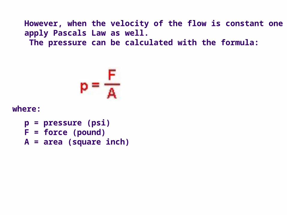
However, when the velocity of the flow is constant one may apply Pascals Law as well. The pressure can be calculated with the formula:
p = pressure (psi) F = force (pound) A = area (square inch)
where:
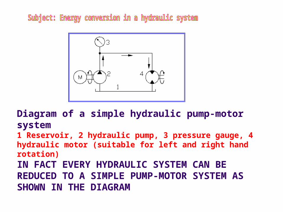
Diagram of a simple hydraulic pump-motor system 1 Reservoir, 2 hydraulic pump, 3 pressure gauge, 4 hydraulic motor (suitable for left and right hand rotation)
IN FACT EVERY HYDRAULIC SYSTEM CAN BE REDUCED TO A SIMPLE PUMP-MOTOR SYSTEM AS SHOWN IN THE DIAGRAM

The hydraulic pump is driven by an electric motor or a combustion engine. The hydraulic pump (2) sucks oil from the reservoir (1) and pumps the oil through the pipelines and hoses to the hydraulic motor (4). The hydraulic motor for example drives a winch. So the hydraulic pump converts mechanical energy into hydraulic energy (pressure and flow) and the hydraulic motor converts the hydraulic energy into mechanical energy again! From the exhaust side of the hydraulic motor the oil flows back to the reservoir. In the returnline the pressure is almost zero! The pressure needed to drive the hydraulic motor can be read on the pressure gauge (3), and is determined by the resistence in the system. The most important resistance is the load to be driven by the hydraulic motor (4)! Lines and hoses also have a certain influence on the level of pressure. The speed of the hyraulic motor is determined by it's dimension (displacement) and by the flow that is pumpt into it.

For simple systems with a relatively low level of pressure (about 140 to 180 bar or 14 to 18 MPa) the gearpump is the most used type of pump. The gearpump is a very simple, reliable, relatively cheap and less dirt sensitive hydraulic pump. The pump in the picture is driven in the indicated direction. As the gears rotate and the teeth at the suction side come clear of the meshing point, a vacuum is created and oil flows into the spaces between the theeth.

The oil in the chambers is transported to the pressure side of the pump. There the teeth mesh and the oil is forced out the spaces between the theeth into the output port of the pump. The meshing of the teeth prevents the oil flowing back from the pressure to the suction side of the pump. So the oil is transported from the suction side to the pressure side along the housing side of the gear wheels! The pressure at the pressure side is determined by the resistance in the system. The most important resistance is the load on the hydraulic cilinder or hydraulic motor. In order to prevent cavitation, the pressure at the suction side of the pump should not exceed 0.1 to 0.2 bar (10 to 20 kPa) below atmospheric pressure (minimim absolute pressure: 0.8 bar or 80 kPa).


The drawing shows a gearpump with three wheels. The wheel in the center is driven by the pump shaft. Comparing this pump with a two wheel pump, the delivery of this pump is twice as high.The two suction and pressure ports are internally connected. The functioning of this pump is just the same as the functioning of the ‘GEAR PUMP’
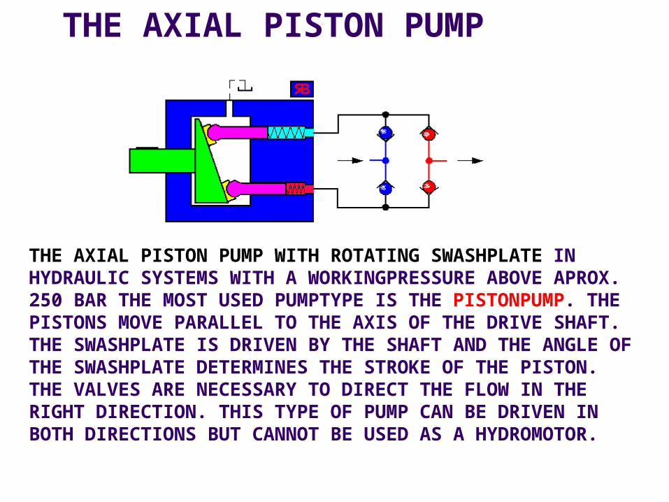
THE AXIAL PISTON PUMP
THE AXIAL PISTON PUMP WITH ROTATING SWASHPLATE IN HYDRAULIC SYSTEMS WITH A WORKINGPRESSURE ABOVE APROX. 250 BAR THE MOST USED PUMPTYPE IS THE PISTONPUMP. THE PISTONS MOVE PARALLEL TO THE AXIS OF THE DRIVE SHAFT. THE SWASHPLATE IS DRIVEN BY THE SHAFT AND THE ANGLE OF THE SWASHPLATE DETERMINES THE STROKE OF THE PISTON. THE VALVES ARE NECESSARY TO DIRECT THE FLOW IN THE RIGHT DIRECTION. THIS TYPE OF PUMP CAN BE DRIVEN IN BOTH DIRECTIONS BUT CANNOT BE USED AS A HYDROMOTOR.

The axial piston pump with variable displacement The animation shows how the displacement of an axial piston pump can be adjusted. In this example we use an AXIAL PISTON PUMP with a rotating cilinder barrel and a static' swashplate. The cilinder barrel is driven by the drive shaft which is guided through a hole in the swashplate. The position (angle) of the swashplate determines the stroke of the pistons and therefore the amount of displacement (cm3/omw) of the pump. By adjusting the position of the swashplate the amount of displacement can be changed. The more the swashplate turns to the vertical position, the more the amount of displacement decreases. In the vertical position the displacement is zero. In that case the pump may be driven but will not deliver any oil. Normally the swashplate is adjusted by a hydraulic cilinder built inside the pumphousing.


On many industrial installations with a maximum pressure of about 200 bar, vane pumps are applied. The advantage of vane pumps is the pulse free delivery and low level of noise. The shaft of the rotor with the radial mounted vanes is driven by an engine or motor.
The stator ring is circular in form and is held in an eccentric position. The amount of eccentricity determines the displacement of the pump. When the amount of eccentricity is decreased to zero, the displacement of the pump becomes 0 cm3: from that moment on the pump doesn't deliver any oil.
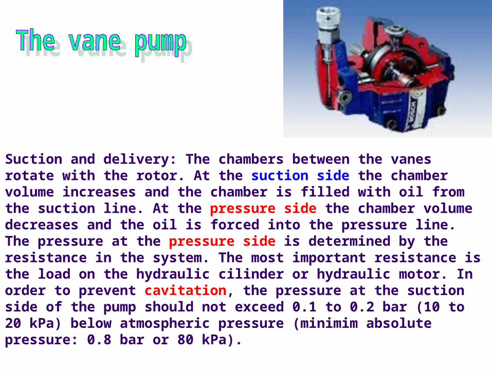
Suction and delivery: The chambers between the vanes rotate with the rotor. At the suction side the chamber volume increases and the chamber is filled with oil from the suction line. At the pressure side the chamber volume decreases and the oil is forced into the pressure line.The pressure at the pressure side is determined by the resistance in the system. The most important resistance is the load on the hydraulic cilinder or hydraulic motor. In order to prevent cavitation, the pressure at the suction side of the pump should not exceed 0.1 to 0.2 bar (10 to 20 kPa) below atmospheric pressure (minimim absolute pressure: 0.8 bar or 80 kPa).

THE VANE PUMP WITH VARIABLE DISPLACEMENT

On many industrial installations with a maximum pressure of about 200 bar, vane pumps are applied. This type of pump is also available with a variable displacement. The shaft of the rotor with the radial mounted vanes is driven by an engine or motor. The stator ring is circular in form and is held in an eccentric position. The amount of eccentricity determines the displacement of the pump. By steering the stator ring towards the rotor (by hydraulic pressure, working on a piston) the amount of eccentricity and thus the displacement of the pump is decreased. At an eccentricity of zero, the displacement of the pump becomes 0 cm3: from that moment on the pump doesn't deliver any oil.

This axial piston pump consists of a non rotating swashplate (green) and a rotating barrel (light blue). The advantage of this construction is that the pump can operate without valves because the rotating barrel has a determined suck and pressure zone. The animation shows the behaviour of only one piston; normally this pump has 5, 7, 9 or 11 pistons
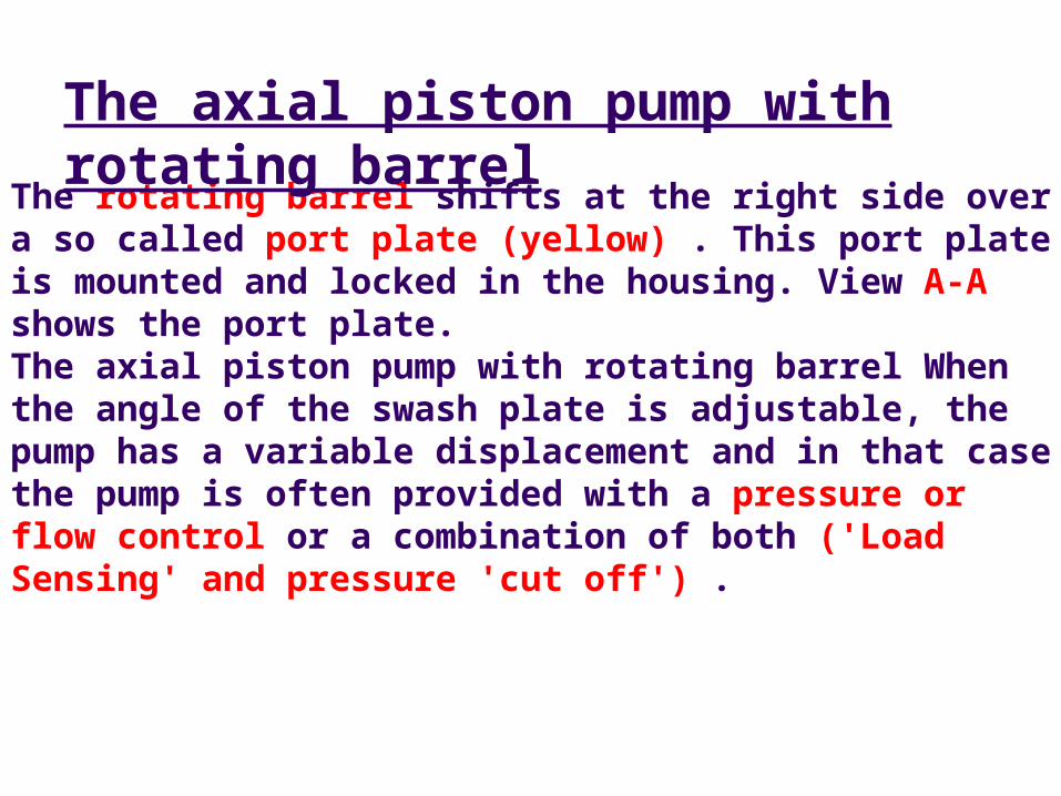
The rotating barrel shifts at the right side over a so called port plate (yellow) . This port plate is mounted and locked in the housing. View A-A shows the port plate. The axial piston pump with rotating barrel When the angle of the swash plate is adjustable, the pump has a variable displacement and in that case the pump is often provided with a pressure or flow control or a combination of both ('Load Sensing' and pressure 'cut off') .
The axial piston pump with rotating barrel
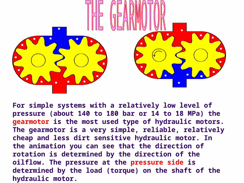
For simple systems with a relatively low level of pressure (about 140 to 180 bar or 14 to 18 MPa) the gearmotor is the most used type of hydraulic motors. The gearmotor is a very simple, reliable, relatively cheap and less dirt sensitive hydraulic motor. In the animation you can see that the direction of rotation is determined by the direction of the oilflow. The pressure at the pressure side is determined by the load (torque) on the shaft of the hydraulic motor.
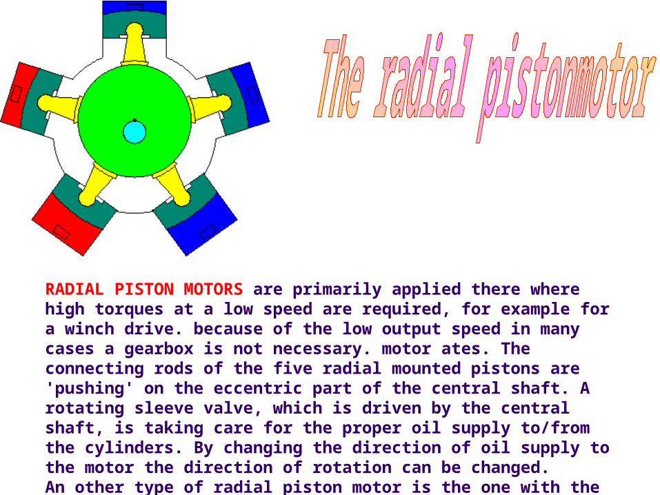
RADIAL PISTON MOTORS are primarily applied there where high torques at a low speed are required, for example for a winch drive. because of the low output speed in many cases a gearbox is not necessary. motor ates. The connecting rods of the five radial mounted pistons are 'pushing' on the eccentric part of the central shaft. A rotating sleeve valve, which is driven by the central shaft, is taking care for the proper oil supply to/from the cylinders. By changing the direction of oil supply to the motor the direction of rotation can be changed. An other type of radial piston motor is the one with the internal radial


JUST LIKE THE RADIAL PISTON MOTOR OF THESTAR TYPE, THE INTERNAL RADIAL PISTON MOTOR IS APPLIED THERE WHERE HIGH TORQUES ARE REQUIRED. OF THIS TYPE OF HYDRAULIC MOTOR THERE ARE MOTORS AVAILABLE WITH A DISPLACEMENT OF 300 LITER/ROTATION AND AN OUTPUT TORQUE OF MORE THAN 1,400,000 NM! FOR EXAMPLE, THEY ARE USED TO DRIVE WINCHES, SHREDDERS, WHEELS, BUCKET WHEELS.
The barrel with the eight radial mounted pistons rotates over a fixed shaft which has the function of a sleeve valve. At the right moment a piston is pushed outwards and the roller which is connected to the piston, has to 'follow' the curved and fixed mounted ring. This results in a rotation of the barrel; the barrel is connected to the output shaft of the motor and drives the load. By changing the direction of oil supply to the motor the direction of rotation can be changed.

The radial piston motor as a wheel motor
This radial piston motor has a static barrel and a rotating housing. It works just like the radial piston motor with the rotating barrel The rotating housing is connected to a wheel so in fact this construction represents a wheel with integrated hydraulic motor. The barrel with the eight radial mounted pistons is fixed; the housing and the central sleeve valve rotate. The central sleeve valve takes care for the distribution of the oil.At the right moment a piston is pushed outwards and the roller which is connected to the piston, pushes the housing with the curved ring aside. This results in a rotation of the housing with the wheel.By changing the direction of oil supply to the motor the direction of rotation can be changed
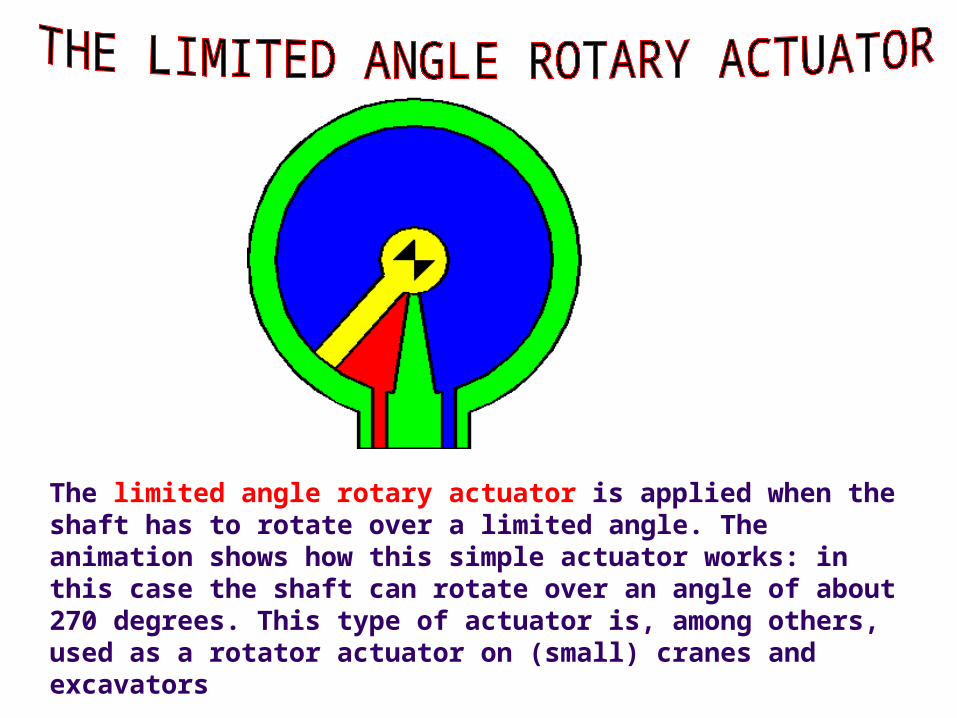
The limited angle rotary actuator is applied when the shaft has to rotate over a limited angle. The animation shows how this simple actuator works: in this case the shaft can rotate over an angle of about 270 degrees. This type of actuator is, among others, used as a rotator actuator on (small) cranes and excavators

The pressure relief valve
Drawing and simulation of a direct operating pressure relief valve: left: valve closed; middle: symbol of a direct operating pressure relief valve according to ISO 1219; right: simulation of an operating pressure relief valve
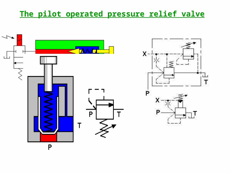
The pilot operated pressure relief valve
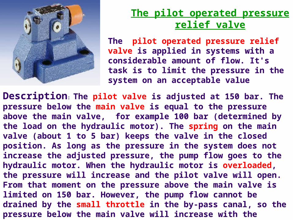
The pilot operated pressure relief valve
The pilot operated pressure relief valve is applied in systems with a considerable amount of flow. It's task is to limit the pressure in the system on an acceptable value
Description: The pilot valve is adjusted at 150 bar. The pressure below the main valve is equal to the pressure above the main valve, for example 100 bar (determined by the load on the hydraulic motor). The spring on the main valve (about 1 to 5 bar) keeps the valve in the closed position. As long as the pressure in the system does not increase the adjusted pressure, the pump flow goes to the hydraulic motor. When the hydraulic motor is overloaded, the pressure will increase and the pilot valve will open. From that moment on the pressure above the main valve is limited on 150 bar. However, the pump flow cannot be drained by the small throttle in the by-pass canal, so the pressure below the main valve will increase with the spring pressure of about 1 to 5 bar (the pressure below the main valve will increase to 151...155 bar). Then the main valve opens and the majority of the pump flow will be drained by the main valve.

THE PILOT OPERATED PRESSURE RELIEF VALVE AS AN UNLOADING VALVE
THE PILOT OPERATED PRESSURE RELIEF VALVE CAN ALSO BE APPLIED AS AN UNLOADING VALVE. NORMALLY THE 2/2-DIRECTION CONTROL VALVE IS ACTIVATED AND THE OPENING PRESSURE OF THE MAIN VALVE IS DETERMINED BY THE PILOT VALVE. IF THE 2/2-DIRECTION CONTROL VALVE IS NOT ACTIVATED THE PRESSURE AT THE UPPER SIDE OF THE MAIN VALVE WILL BECOME ZERO. THE PRESSURE AT THE BOTTOM SIDE OF THE MAINE VALVE WILL OPEN THE MAIN VALVE: THE PRESSURE NEEDED TO DO THIS WILL BE ABOUT 3 BAR (ALMOST ZERO). FROM THAT MOMENT ON THE MAJORITY OF THE PUMPFLOW WILL BE DRAINED TOWARDS THE RESERVOIR BY THE MAIN VALVE
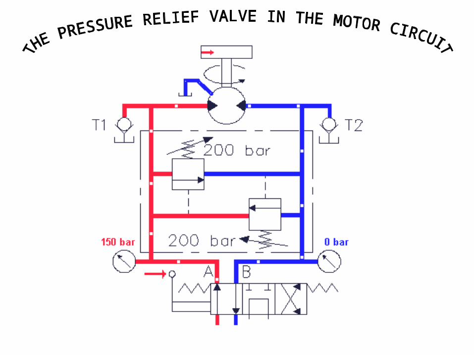
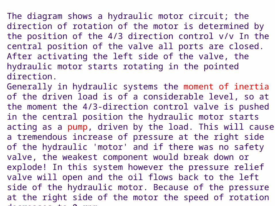
The diagram shows a hydraulic motor circuit; the direction of rotation of the motor is determined by the position of the 4/3 direction control v/v In the central position of the valve all ports are closed. After activating the left side of the valve, the hydraulic motor starts rotating in the pointed direction. Generally in hydraulic systems the moment of inertia of the driven load is of a considerable level, so at the moment the 4/3-direction control valve is pushed in the central position the hydraulic motor starts acting as a pump, driven by the load. This will cause a tremendous increase of pressure at the right side of the hydraulic 'motor' and if there was no safety valve, the weakest component would break down or explode! In this system however the pressure relief valve will open and the oil flows back to the left side of the hydraulic motor. Because of the pressure at the right side of the motor the speed of rotation decreases to 0 rpm.The hydraulic motor has an external leakage line so there will disappear oil from the motorcircuit. This may cause cavitationat the left side of the motor. In this system however the circuit is protected against cavitation by the check valves (suction valves). The diagram on this page forms a basic diagram for most motor circuits

Symbol of a 4/3-direction control valve
With a direction control valve you determine the direction of the flow and therefore the direction of operation of a hydraulic motor or cilinder. In the animation we use a so called 4/3-direction control valve ; the 4/3 comes from: 4 line connections and 3 positions.
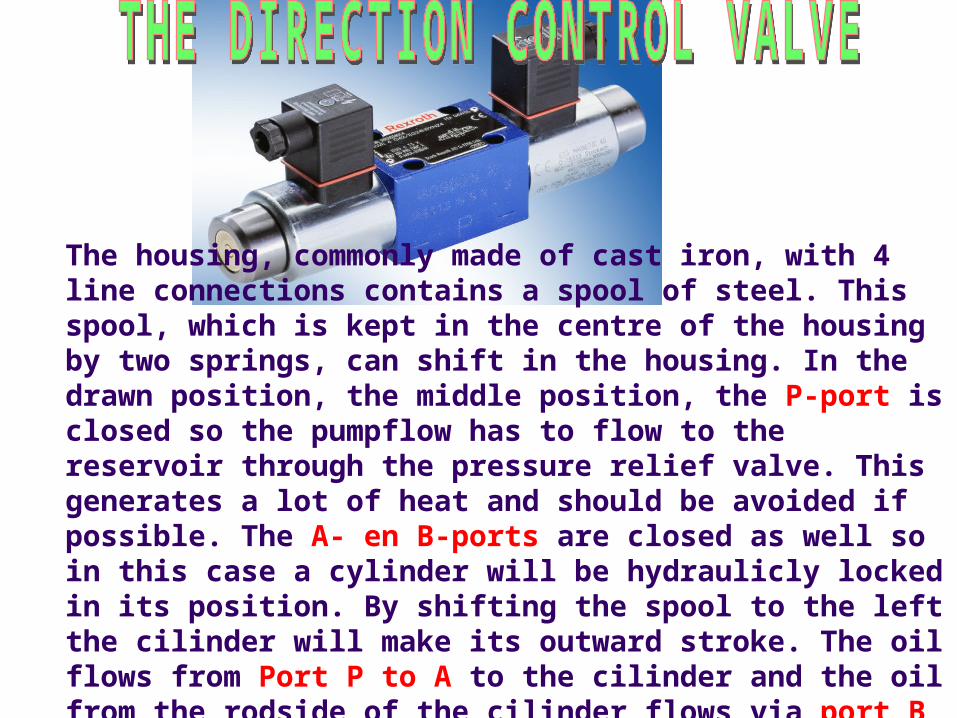
The housing, commonly made of cast iron, with 4 line connections contains a spool of steel. This spool, which is kept in the centre of the housing by two springs, can shift in the housing. In the drawn position, the middle position, the P-port is closed so the pumpflow has to flow to the reservoir through the pressure relief valve. This generates a lot of heat and should be avoided if possible. The A- en B-ports are closed as well so in this case a cylinder will be hydraulicly locked in its position. By shifting the spool to the left the cilinder will make its outward stroke. The oil flows from Port P to A to the cilinder and the oil from the rodside of the cilinder flows via port B to T back to the reservoir.

The flow control
In order to control the velocity of a hydraulic motor or cylinder you have to control the flow. In this example the flow to the cylinder is controlled by a simple Flow control. . The pressure behind the flowcontrol is determined by the load on the cylinder and is in this case 80 bar. De flow control is adjusted on a flow of 8 l/min. The hydraulic pump delivers 12 l/min so a part of the pumpflow, 4 l/min flows through the pressure relief valve back to the reservoir. The pressure before the flow control is determined by the pressure relief valve, in this case 120 bar. The pressure drop in the flowcontrol (40 bar) and in the pressure relief valve (120 bar) is converted into heat. This kind of flow control is relatively cheap but has a low energy efficiency

The pressure compensated flow control
Controlling the velocity of a hydraulic cylinder by controlling the flow with a pressure compensated flow control

To control the velocity of a hydraulic motor or cylinder one has to control the flow to these components. This can be done with a simple flow control .The flow through a flow control is determined by:a) The area of the flow control: a larger area means a higher amount of flow andb) the pressure drop across the flow control: an increase of the pressure drop means an increase of flow The flow is also determined by the construction of the flow control and by the viscosity of the fluid, but these factors are neglected.

Example: in a system with a flow control the pressure at the pump side is determined by the pressure relief valve (see also flow control). When the pressure drop across the flow control decreases as a result of an increase of the load on the cylinder the flow and velocity of the cylinder will increase as well. If the velocity has to remain constant and independent of the load one has to use a pressure compensated flow control
The pilot operated check valve
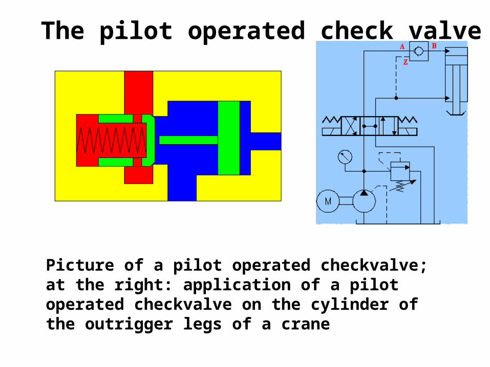
Picture of a pilot operated checkvalve; at the right: application of a pilot operated checkvalve on the cylinder of the outrigger legs of a crane
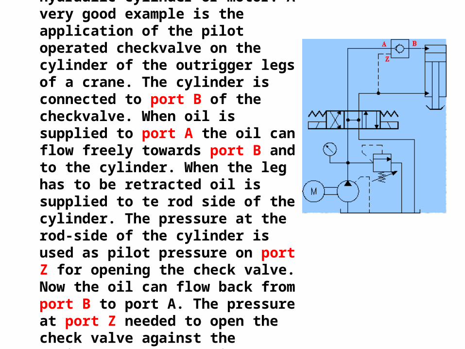
A pilot operated check valve is used to keep a part of the system free from internal leakage for example a hydraulic cylinder or motor. A very good example is the application of the pilot operated checkvalve on the cylinder of the outrigger legs of a crane. The cylinder is connected to port B of the checkvalve. When oil is supplied to port A the oil can flow freely towards port B and to the cylinder. When the leg has to be retracted oil is supplied to te rod side of the cylinder. The pressure at the rod-side of the cylinder is used as pilot pressure on port Z for opening the check valve. Now the oil can flow back from port B to port A. The pressure at port Z needed to open the check valve against the cylinder pressure behind the main valve is about 1/3 to 1/10 (called the opening ratio) of the cylinder pressure

Cross section of a counterbalance valve
In fact a counterbalance valve is an improved pilot operated check valve

An important and major difference between these two valves is:- the opening pressure of a pilot operated check valve depends on the pressure (applied by the load) behind the valve;- the opening pressure of a counterbalance valve depends on the spring pressure behind the valve.The dynamic performance of a balance valve is many times better than the dynamic performance of a pilot operated check valve The balance valve is applied as a 'brake valve' on relatively small crane systems in order to get a positive control on a hydraulic cylinder or motor with a negative load.

Functioning (see diagram): When the left side of the 4/3-direction control valve is activated the cylinder will make its 'OUT-stroke'. The oil flows through the check valve which is integrated in the housing of the balance valve. In order to lower the cylinder, the right side of the 4/3-direction control valve has to be activated. From that moment on pressure is built up at the rod side of the cylinder. This pressure opens the balance valve and the oil at the bottom side of the cylinder flows through the balance valve and the direction control valve back to the reservoir

As the load helps lowering the cylinder, the cylinder might go down faster than the oil is applied to the rod side of the cylinder (the cylinder isn't under control at that moment). However, the pressure at the rod side of the cylinder and therefore the pilot pressure on the balance valve will decrease and the spring moves the balance valve to the direction 'close' as long as it finds a new 'balance'. When the direction control valve is suddenly put in the middle position while lowering the loaded cylinder, the counterbalance valve closes immediately. This will cause an increase of pressure at the bottom side of the cylinder. However, the counterbalance valve will open at the adjusted pressure and thus protects the cylinder against overpressure
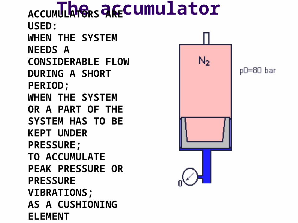
The accumulatorACCUMULATORS ARE USED:WHEN THE SYSTEM NEEDS A CONSIDERABLE FLOW DURING A SHORT PERIOD; WHEN THE SYSTEM OR A PART OF THE SYSTEM HAS TO BE KEPT UNDER PRESSURE; TO ACCUMULATE PEAK PRESSURE OR PRESSURE VIBRATIONS; AS A CUSHIONING ELEMENT
In hydraulic systems the following types of accumulators are used:the piston accumulator; animation (to supply oil; reliable; relatively slow accumulator as a result of friction between piston and cylinder) the bladder accumulator (to supply oil; 'fast' accumulator) the diaphragm accumulator (cushioning element; pressure compensator) This example explains the functioning of the piston accumulator (animation) ; the functioning of the other types is similar to this one. At one side of the piston the accumulator is filled with nitrogen gas. The pressure of the gas at the gas side of the accumulator has to have a certain pressure, in this case 80 bar (8 MPa). This pressure, prescript by the manufacturer of the system, has to be checked when there is no oil at the other side of the piston.
At the moment that the accumulator is filled with oil, the
pressure at the oil side increases to the level of the gas
pressure immediately. In the animation you can see this
happen. For an appropriate functioning of the system,
the gaspressure has to have the right value.
The manufacturer prescribes how often the pressure has
to be checked.

Watch out: accumulators accumulate hydraulic energy and therefore can be very dangerous, especially when you are not familiar with the system and accumulators!!When repairing or modifying a hydraulic system be sure that the accumulator is drained and shut off as instructed by the manufacturer!
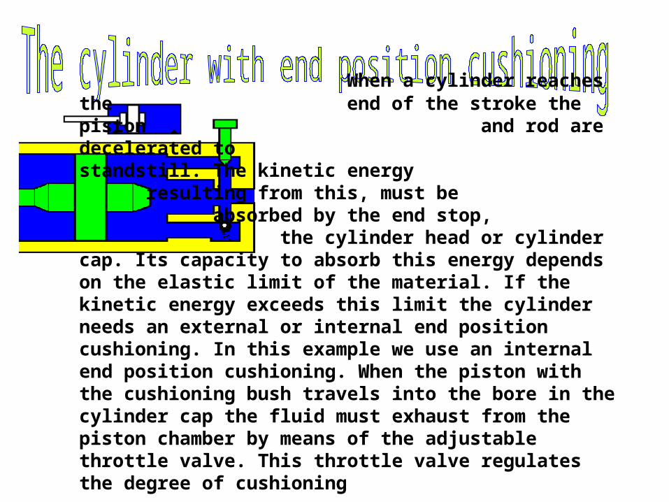
When a cylinder reaches the end of the stroke the piston and rod are decelerated to standstill. The kinetic energy resulting from this, must be
absorbed by the end stop, the cylinder head or cylinder cap. Its
capacity to absorb this energy depends on the elastic limit of the material. If the kinetic energy exceeds this limit the cylinder needs an external or internal end position cushioning. In this example we use an internal end position cushioning. When the piston with the cushioning bush travels into the bore in the cylinder cap the fluid must exhaust from the piston chamber by means of the adjustable throttle valve. This throttle valve regulates the degree of cushioning

CYLINDER WITH END POSITION CUSHIONING

The closed loop system with main pump on zero displacement

The closed loop system with activated main pump
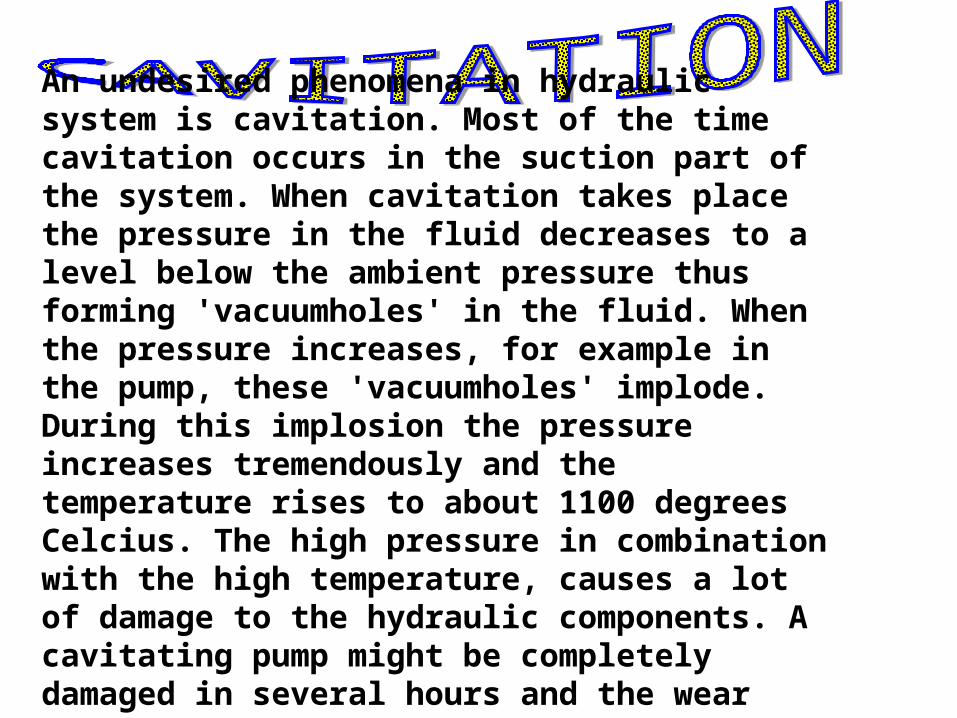
An undesired phenomena in hydraulic system is cavitation. Most of the time cavitation occurs in the suction part of the system. When cavitation takes place the pressure in the fluid decreases to a level below the ambient pressure thus forming 'vacuumholes' in the fluid. When the pressure increases, for example in the pump, these 'vacuumholes' implode. During this implosion the pressure increases tremendously and the temperature rises to about 1100 degrees Celcius. The high pressure in combination with the high temperature, causes a lot of damage to the hydraulic components. A cavitating pump might be completely damaged in several hours and the wear parts may cause damage in the system
CAVITATION
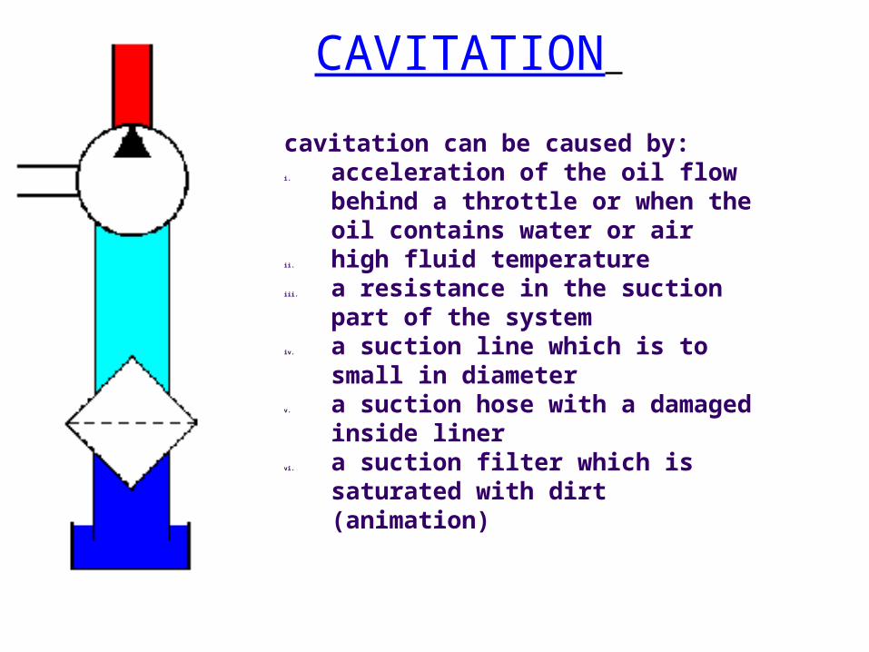
cavitation can be caused by:i. acceleration of the oil flow
behind a throttle or when the oil contains water or air
ii. high fluid temperature iii. a resistance in the suction part
of the system iv. a suction line which is to small
in diameter v. a suction hose with a damaged
inside liner vi. a suction filter which is
saturated with dirt (animation)

Compressibility of fluidsMany people think that a fluid is incompressible. However, fluids are, like any material, in a certain amount compressible. In calculations the amount of compressibility of fluid is considered to be 1 volume-% per 100 bar . This means that for example when there is fluid supplied to a 200 litre oil drum which already is completely filled with fluid (see animation), the pressure increases with 100 bar for each 2 litre of extra supplied fluid. When we supply 3 litre of extra oil the pressure increases with 150 bar. The compressibility of fluid plays a key role in for example fast hydraulic systems like servo-systems of a flight simulator. To obtain a maximum dynamic performance, the compressibility should be as less as possible. This is achieved by mounting the control valves directly on the hydraulic motor or cylinder. In that case the amount of fluid between the control valve and the motor/cylinder is as less as possible
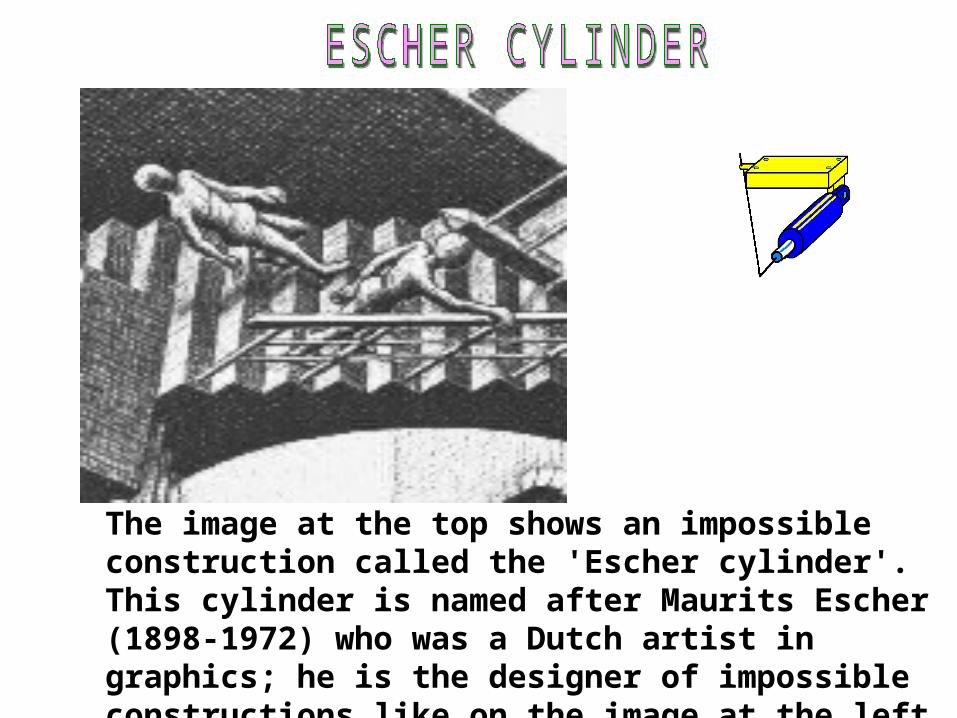
The image at the top shows an impossible construction called the 'Escher cylinder'. This cylinder is named after Maurits Escher (1898-1972) who was a Dutch artist in graphics; he is the designer of impossible constructions like on the image at the left

How to determine the condition of the hardest working component of a hydraulic system - the pump. As a pump wears in service, internal leakage increases and therefore the percentage of flow available to do useful work (volumetric efficiency) decreases. If volumetric efficiency falls below a level considered acceptable for the application, the pump will need to be overhauled. In a condition-based maintenance environment, the decision to change-out the pump is often based on remaining bearing life or deterioration in volumetric efficiency, whichever occurs first. Volumetric efficiency is the percentage of theoretical pump flow available to do useful work. It is calculated by dividing the pump's actual output in liters or gallons per minute by its theoretical output, expressed as a percentage. Actual output is determined using a flow-tester to load the pump and measure its flow rate.

Because internal leakage increases as operating pressure increases and fluid viscosity decreases, these variables should be stated when stating volumetric efficiency. For example, a hydraulic pump with a theoretical output of 100 GPM, and an actual output of 94 GPM at 5000 PSI and 120 SUS is said to have a volumetric efficiency of 94% at 5000 PSI and 120 SUS. When calculating the volumetric efficiency of a variable displacement pump, internal leakage must be expressed as a constant. To understand why this is so, think of the various leakage paths within a hydraulic pump as fixed orifices. The rate of flow through an orifice is dependant on the diameter (and shape) of the orifice, the pressure drop across it and fluid viscosity. This means that if these variables remain constant, the rate of internal leakage remains constant, independent of the pump's displacement.