Embed Size (px)
Citation preview

What Does Stability Mean?• Stability circles determine what load or source
impedances should be avoided for stable or non-oscillatory amplifier behavior
• Because reactive loads are being added to amp the conditions for oscillation must be determined
• So the Output Stability Circle determine the ΓL or load impedance (looking into matching network from output of amp) that may cause oscillation
• Input Stability Circle determine the ΓS or impedance (looking into matching network from input of amp) that may cause oscillation

Criteria for Unconditional Stability• Unconditional Stability when amplifier
remains stable throughout the entire domain of the Smith Chart at the operating bias and frequency. Applies to input and output ports.
• For |S11| < 1 and |S22| < 1, the stability circles reside completely outside the |ΓS| = 1 and |ΓL| = 1 circles.
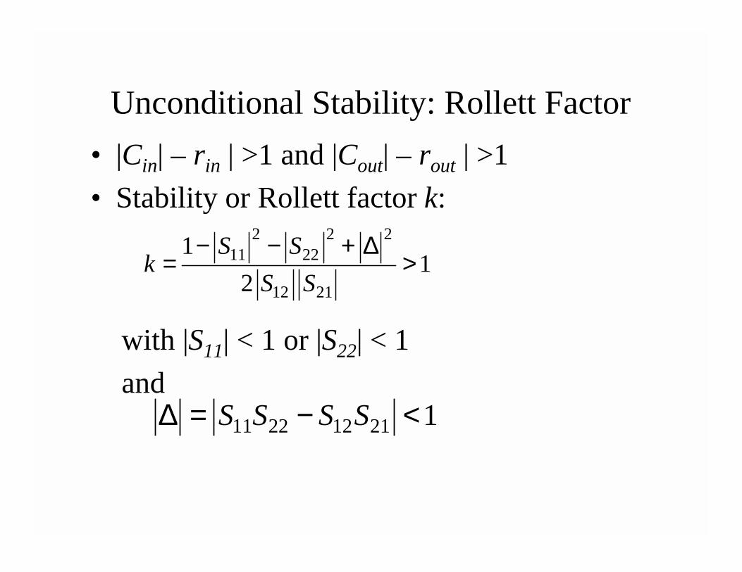
Unconditional Stability: Rollett Factor• |Cin| – rin | >1 and |Cout| – rout | >1 • Stability or Rollett factor k:
2 2 211 22
12 21
11
2S S
kS S
− − + ∆= >
with |S11| < 1 or |S22| < 1and
11 22 12 21 1S S S S∆ = − <

Stabilization Methods• Stabilization methods can be used to for
operation of BJT or FET found to be unstable at operating bias and frequency
• One method is to add series or shunt conductance to the input or output of the active device in the RF signal path to “move” the source or load impedances out of the unstable regions as defined by the Stability Circles

Stabilization Using Series Resistance or Shunt Conductance
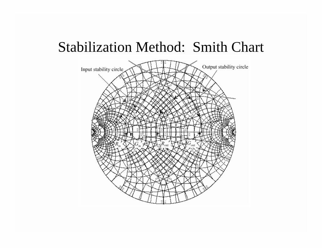
Stabilization Method: Smith Chart

Constant Gain: Unilateral Design (S12= 0)• Need to obtain desired gain performance• Basically we can “detune” the amp
matching networks for desired gain• Unilateral power gain GTU implies S12 = 0

Unilateral Power Gain Equations• Unilateral Power gain
2 22
21 02 211 22
1 1
1 1S L
TU S LS L
G S G G GS S
− Γ − Γ= =
− Γ − Γ
• Individual blocks are: 2 2
20 212 2
11 22
1 1
1 1S L
S LS L
G ; G S ; GS S
− Γ − Γ= = =
− Γ − Γ
• GTU (dB) = GS(dB) + G0(dB) +GL(dB)

Unilateral Gain Circles
max max2 211 22
1 11 1
S LG ; GS S
= =− −
• If |S11| < 1 and |S22 |< 1 maximum unilateral power gain GTUmax when ΓS = S11* and ΓL = S22*
• Normalized GS w.r.t. maximum:
( )2
2112
max 11
11
1SS
SS S
Gg SG S
− Γ= = −
− Γ

Unilateral Gain Circles
• Results in circles with center and radii:
( )2
2222
max 22
11
1LL
LL L
Gg SG S
− Γ= = −
− Γ
• Normalized GL w.r.t. maximums:
( )( )( )
2
2 2
1 1
1 1 1 1i i
i iii iig g
ii i ii i
g Sg Sd ; rS g S g
− −= =
− − − −
ii = 11 or 22 depending on i = S or L

Gain Circle Observations• Gi max when Γi = Sii* and dgi = Sii* of radius
rgi = 0• Constant gain circles all have centers on
line connecting the origin to Sii* • For the special case Γi = 0 the normalized
gain is:gi = 1 - | Sii |2 and dgi = rgi = | Sii |/(1 + | Sii |2)
• This implies that Gi = 1 (0dB) circle always passes through origin of Γi - plane

Input Matching Network Gain Circles
ΓS is detuned implying the matching network is detuned

Bilateral Amplifier Design (S12 included)• Complete equations required taking into
account S12: Thus ΓS* ≠ S11 and ΓL* ≠ S22
12 21 1111
22 221 1* L LS
L L
S S SSS S
Γ − Γ ∆Γ = + =− Γ − Γ
12 21 2222
11 111 1* S SL
S S
S S SSS S
Γ − Γ ∆Γ = + =− Γ − Γ

Bilateral Conjugate Match• Matched source reflection coefficient
21 1 1
1 1 1
1 42 2
*
MSB B CC C C
Γ = − −
2 2 2
1 11 22 1 22 111*C S S ; B S S= − ∆ = − − ∆ +
• Matched load reflection coefficient2
2 2 2
2 2 2
1 42 2
*
MLB B CC C C
Γ = − −
2 2 22 22 11 2 11 221*C S S ; B S S= − ∆ = − − ∆ +

Optimum Bilateral Matching
12 2111
221MS
* ML
ML
S SSS
ΓΓ = +− Γ
12 2122
111ML
* MS
MS
S SSS
ΓΓ = +− Γ

Design Procedure for RF BJT Amps• Bias the circuit as specified by data sheet
with available S-Parameters• Determine S-Parameters at bias conditions
and operating frequency• Calculate stability |k| > 1 and |∆| < 1?• If unconditionally stable, design for gain• If |k| ≤ 1 and |∆| ≥1 then draw Stability
Circles on Smith Chart by finding rout, Cout, rin, and Cin radii and distances for the circles

Design Procedure for RF BJT Amps• Determine if ΓL ( S22* for conjugate match)
lies in unstable region – do same for ΓS• If stable, no worries. • If unstable, add small shunt or series
resistance to move effective S22* into stable region – use max outer edge real part of circle as resistance or conductance (do same for input side)
• Can adjust gain by detuning ΓL or ΓS

Design Procedure for RF BJT Amps• To design for specified gain, must be less than
GTU max (max unilateral gain small S12)• Recall that (know G0 = |S21|2)
GTU [dB] = GS [dB] + G0 [dB] + GL [dB]• Detune either ΓS or ΓL
• Draw gain circles for GS (or GL) for detuned ΓS (or ΓL) matching network
• Overall gain is reduced when designed for (a) Stability and (b) detuned matching netw0rk

Design Procedure for RF BJT Amps• Further circles on the Smith Chart include
noise circles and constant VSWR circles• Broadband amps often are feedback amps

RF Shunt-Shunt Feedback Amp Design
( )1 0 211R Z S= − 0
2
21
1
m
ZR
R g= −
Cm
T
IgV
= S21 calculated from desired gain G
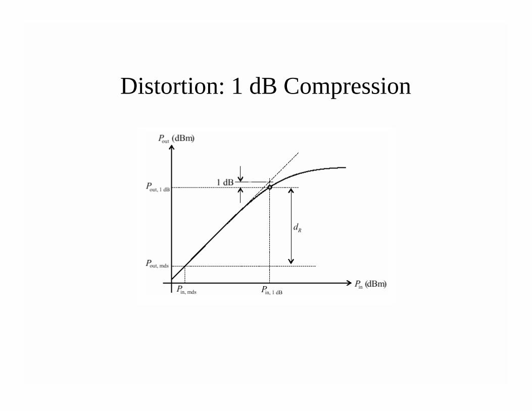
Distortion: 1 dB Compression

Distortion: 3rd Order IntermodulationDistortion

Distortion: 3rd Order IMD[ ] ( )[ ] [ ]2 2 13 dB dBm (2 ) dBmout outIMD P f P f f= − −
[ ] [ ] [ ] [ ]( )0 ,2dB dBm dB dBm3f in mdsd IP G P= − −
Spurious Free Dynamic Range