Embed Size (px)
Citation preview

IEEE TRANSACTIONS ON INDUSTRY AND GENERAL APPLICAITIONS, VOL. IGA-4, NO. 4, JULY/AUGUST 1968
What Can Be Done in Power System Design to
Improve ReliabilityWALTER C. BLOOLIQUIST, FELLOW, IEEE
Abstract-The available quality and variety of present-day powerequipment and the system design technology permit the tailoring of asystem to meet the reliability requirements of the user. How-ever, system planning must be reemphasized in power system designwhich has been of deteriorating reliability and not necessarily themost economical
This paper describes some of the system and circuit arrangementsand other related factors that are necessary to obtain reliable,economical, and responsive modern power systems.
GENERAL CONSIDERATIONS FOR RELIABILITY
THIS PAPER will not offer any radical new systemdevelopments or products to improve reliability. In
fact, products, system and circuit arrangements, andtechnical material are available to aid in designing areliable power system [1]- [5]. Previous authors havecovered many of the associated specific points. This paperwill serve its purpose by reaffirming sound power systemprinciples.
Industry does not yet have a "reliability index" forsystem arrangements and components, although a reliabil-ity evaluation is made of some power systems for groundand support systems associated with the space and missileprogram. Dickinson reported on an IEEE-sponsored sur-vey on reliability data in industrial plants [6]. Electricutilities have done a great deal of work in this area;their work and collection of data should also be usefulto industry. As management techniques grow moresophisticated, detailed reliability or operational risk goalswill be developed for industry which will be helpful in theselection of power system arrangements.But until more quantitative statistical information is
available, it is wise to obtain the necessary degree ofreliability via power system design practices that haveproven sound and economical.
In industrial plants and commercial buildings the follow-ing is good practice.Axiom Simplicity improves reliability (especially im-
portant when redundancy is being considered).Rule-Operating practices for emergencies must be
simple and safe.
Paper approved by the Industrial and Commercial Power SystemsCommittee for presentation at the 1968 IEEE Industrial and Com-merical Power Systems and Electric Space Heating and Air Condi-tioning Joint Technical Conference, St. Louis, Mo., May 7-10.Manuscript received June 5, 1968.The author is with the General Electric Company, Schenectady,
N. Y.
DEGREE OF RELIABILITY NEEDED
What degree of reliability (or availability) is required?How is it determined and by whom? What is the cost ofdowntime? What business or engineering factors enter intothe decision on reliability? These can best be answered bythe individual plant. However, it should be emphasizedthat business management is now becoming more andi moreconcerned with power outages and associated manufactur-ing losses. As plants become more fully automated evenoccasional power outages can cause enormous losses. Andthere are the intangibles that may be important, as a fewexamples will illustrate. In one case a plant operating in avery competitive field was faced not onlv with productionlosses but also with the possible loss of a big customer be-cause of its inability to deliver products to meet thecustomer's production schedule. In many cases a companymust pay workers at least a half a day's wages even if theyare sent home for reasons beyond their cotntrol, such aspower system outage. In some cases there is the cost ofdamage to equipment, or the cost of material in processthat must be scrapped.Each plant will have its own cost and profit values.
However, the selling price of a unit of output for a fewtypical industries is as follows.News print mill: $150 per day per ton of capacity.Steel: $100 to $200 per day per ton of capacity for
ordinary varieties.Window glass: $125 to $150 per day per ton of capacity.Cement: $3 per day per barrel of capacity.Sulfuric acid: $20 per day per ton of capacity.Petroleum refining: $4 to $5 per day per barrel of
capacity, depending upon product.One point that is often overlooked is the restorability of
a power service. In many cases it is the cost associated withrestorability of service that is of major importance, e.g.,wages and lost production. Various methods to reduce thetime to restore service are explained elsewhere in thispaper. Equipment features, such as drawout or plug-intype devices, can help reduce this time.
It is important to appreciate that the degree of reliabilityand restorability need not be the same for all parts of aplant. One particular process may be critical, requiring thebest service. Other processes in the same plant may bepractically unaffected by momentary or short power inter-ruptions.
However, once the reliability requirements are knownand uniderstood, it is possible to match the system design
3 -6

BLOOMQUIST: IMPROVING POWER SYSTEM1 RELIABILITY
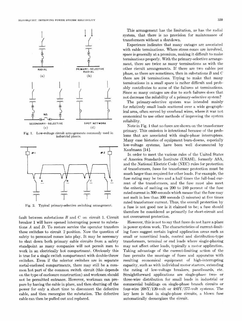
to the service reliability requirements. For example, ifhigher service continuity is desired than available from theradial system of Fig. 1(a), the secondary-selective arrange-ment of Fig. 1(c) offers advantages over a simple radialsystem at a modest increase in cost. If a still higher degreeof service continuity is needed, the spot network of Fig.l(d) can be selected.
It may be most economical to obtain reliability via theinsurance route described in a previous paper by Wedden-dorf [7]. To assume that one must obtain reliability byself-insurance via redundancy may not be good business.
CHARACTERISTICS OF A MODERN POWER SYSTEM [8]Modern power system characteristics are safety, reliabil-
ity, expandability, flexibility, simplicity, and economy:
1) High-quality metal-enclosed equipment for safety,such as switchgear, -unit substations, motor-controlcenters, and plug-in buswav
2) Well installed3) Properly maintained4) Safe operating practices5) Simple circuitry and switching arrangements6) Dual channels for reliability where required for the
process7) Adequate reserve capacity for growth and emergency
operation8) Adequate short-circuit protection9) Ability to accommodate load growth10) Ability to accommodate load shift11) Ability to restore power quickly12) Highest suitable distribution and utilization voltages13) Good voltage regulation14) A means to compensate for voltage drop and dip if
required15) Adequate and proper system and equipment ground-
ing16) Coordinated system protection17) Ability to isolate faulted circuits without affecting
the operation of equipment on other circuits-sen-sitivity, selectivity, speed
18) Capacitors for power-factor improvement as needed19) Surge protection on exposed circuits20) Unnecessary to work on energized equipment21) Uninterruptible power systems for small vital loads22) Emergency power available if required.
NEED FOR PLANNINGAlmost any power distribution electrical engineer can
put together an electric power system that will work. Alltoo often such a system is selected on the basis of minimumfirst cost, with little- attention paid to the fundamentalprinciples of power system planning, which involve per-formance, quality features, and system characteristics thatmay not be well understood.We see fewer and fewer good system layouts. Too many
seem to consist of components tied together with littlebasic engineering attention. Even first-class equipment
cannot produce a good system from a poor arrangement.Yet, there is much fundamental engineering informationavailable so that an engineer with proper thought andstudy can lay out a good economical system [9]. What islacking is planning on an overall basis.Power system reliability and availability are dependent
upon many considerations, for example, consideration ofsafety, load requirements, cost, power sources, selection ofvoltage, voltage drop, relaying, system and equipmentgrounding, circuit arrangements, equipment ratings,power factor, types of conductors, transformers, short-circuitcurrent, operation, maintenance, and the people involved.Each has relation to the other and each affects the overallsystem reliability. Planning can mean the difference be-tween a reliable power system and a poor one.The investment in the power distribution system is
relatively small and generally ranges from two to ten per-cent of the total plant and equipment investment. Usuallythe difference in cost between a well-planned reliable sys-tem and a mediocre one is small. And in many cases wehave seen poor systems that cost more than a better andmore reliable one, mainly due to lack of planning. Like anyother investment, that of the power system must show asuitable return, too. However, the leverage on this invest-ment can be tremendous; pinching a few dollars here canjeopardize the entire investment.One should not forget that the power system is created
to serve loads and, therefore, must be carefully integratedwith the needs of the process.The one-line diagram is a most helpful tool. Not only
will it serve as a constant handy guide for system design,but it will also give a reasonable idea of the expectedservice continuity, how the components fit together, andmany other concepts that are useful to system planning.The tentative one-line diagram will probably be changed
many times during the development of a project. Butchanges on paper are inexpensive as well as easy. If the one-line diagram is kept up-to-date, it will serve as a completerecord of the evaluation of the system design.At each stage in the system development, look over the
one-line diagram for weak points. Assume a failure in eachcircuit or piece of equipment, one atatime, and analyze howmuch of the system that failure would affect. Alwaysdesign to "isolate with a minimum of disturbances" to theplant.Along with the one-line diagram, a plot plan of the
electrical plant load is most helpful and from these twodiagrams a system arrangement can be quickly made.Another useful tool is the impedance diagram. It is help-
ful in pinpointing possible voltage-drop problems, is usefulfor short-circuit calculations for the selection of switchingequipment or for relay settings, and offers guidance forsystem expansion.
Cooperation with the local electric utility is absolutelyessential, and a meeting with them in the early stages ofplanning is a must. Utilities have various types of servicesthat must enter into the overall discussion of cost and
35'7

IEEE TRANSACTIONS ON INDUSTRY AND GENERAL APPLICATIONS, JULYjL-AUGUST 1968
reliability in the planninig stage. These can include singleor multiple services, ownership of the incoming trans-former or substation, voltage regulation, or IC level(this interrupting capacity is a good indication of the"stiffness" of the system).
If modern industrial plants and commercial buildingsare to provide power, with increased reliability, flexibility,and dependability, the known procedures of proper plan-ning must be incorporated in system designs.
NEED FOR STUDIES TO ESTABLISH SYSTEM PERFORMANCE
System studies are now becoming part of system plan-ning in order to improve the system reliability and avail-ability [10].Some studies, for example relay coordination, are an
absolute necessity for assurance that only the minimumoutage occurs for a system disturbance. It is not un-common in a poorly coordinated system for a branch feederfault to take out a large block of power and in some caseseven trip off the incoming service.
Industries with heavy capital investment or the process-type industries, such as steel, chemical, petroleum, andpaper, need studies. They could not afford to do otherwise.There is a definite trend toward system studies made in
advance of equipment purchase. For example, a study mayhelp define the various characteristics of a motor for impactloading service, or indicate the overall system performancefor disturbances, or coordination studies may be made todefine and select the proper protective devices.Almost any system will operate satisfactorily in steady
state, but it is the transient performance that counts, forexample, to remove only the circuit in question, and do itquickly enough so that the rest of the system will remainstable [11].The more common types of studies are:Short-clircuit: These are made to determine the system
short-circuit duties in order to select switching equipmentof the proper rating and to provide short-circuit levels forcoordination of protective devices.
Coordination of protective devices: These are made todetermine the settings of circuit protective devices inorder to obtain selectivity between devices. These aretailored to each power system.
Load-flow: These studies are made to determine theoptimum system and operating condition to provide mnaxi-mum circuit usage, develop kilowatt and kilovar flows,determine proper transformer tap settings, identify systemcapabilities and limitations, and are helpful in establishinga basic plan for future and orderly expansion of systems.These are practically indispensable for determining themost economical operation and arrangement of largecomplex industrial power systems and especially in con-nection with loop-type power systems and those plantshaving local generation.
Stability studies: Such studies are made to determine thestability limits of a system so that sufficiently fast relaysettings may be prescribed to prevent instability whenever
a disturbance such as a fault, switching operation, or thetransient addition or removal of relatively large loadsoccur.The following, taken from Hale and Walsh [121], indicates
the value of studies for a large paper mill complex."The cost of this study was a minor fraction of a percent
of the system investment. The prime value of this study isthat it has established, on a quantitative basis, the presentsystem capabilities and limitations, and to allow forformulation of a guide plan for its enlargement. A mostuseful -document derived by these studies is a listing, indescending order of investment optimization, of steps toimplement the study recomnmenidations.... The study didnot reveal any startling problem areas that were notintuitively evident, but it placed them on a numerical basisso that they could be properly evaluated. The importanceof this cannot be overemphasized. No management can beexpected to authorize corrective action based on intuition,especially on electrical equipment which appears to justsit there and do nothing."
SYSTEM CIRCUITS ARRANGEMENTS-WHICH ONE?
The circuit arrangements of Fig. 1 are those commonlyused in industrial plants for low-voltage service. The sub-ject of redundancy was covered in the previous Bjornsonpaper so it will not be repeated here, although somepertinent points are in order since circuit arrangement in-fluences reliability [13]. Other information is included in[1 ], [2 ], [5 ]. Information relating to primary svstem circuitarrangements is included in [1] and [2].The author is partial to the secondary-selective system,
Fig. 1(c), because of its operating simplicity. It offers theopportunity for mnaintenance or testing of the primarycable circuits, transformers, and the transformer-secondaryor tie breakers without extended power interruption. Thebreakers can be arranged for automatic throw-over ifdesired, thus minimizing the outage time. MAost important,power is available to both low-voltage buses even thoughpower in one primary channel is not available or any of theelements (primary cable, transformer, or transformer-secondary breaker) is out of service.The spot network, Fig. 1(d), (not the distributed net-
work of utilities) is getting increased attentioni for supply-ing power to critical and important loads. Obviously, eithermain channel can be taken out of service without loss ofvoltage or power to the bus providing of course that thetwo primary sources are not from the same bus. This costsmore than the secondary-selective arrangemeint, but it maynot be much more depending upon the substation kVArating (and thus the IC level).The primary-selective system of Fig. 1(b) looks good on
paper but is not so attractive practically. Supposedly, withthis arrangement cable failures (and most outages exceptthose caused by human error are associated with cables andterminations) should be repaired much faster than for thesimple radial system of Fig. 1(a). Let us go through atypical circuit as shown in Fig. 2. Suppose there is a cable
358
BLOOMQ UIST: IMPROVING POWER SYSTEM RELIABILITY
RADIAL
(a)
ll7
4,,
PRIMARY- SELECTIVERA D A L
(b)
Itnn r~~~~~~~~~~~1
elv Cl
N.O.
SECON DAR Y -SELECT VE
(c)
SPOT NET WORK
(d)
Fig. 1. Low-voltage circuit arrallgemenits commonly used inindustrial plants.
T T T T
Fig. 2. Typical primary-selective switchin-g arranigement.
fault between substations B and C oni circuit 1. Circuitbreaker 1 will have opened interrupting power to substa-tions A and D. To restore service the operator transfersthese switches to circuit 2 position. Now the question ofsafety to personnel comes into play. It may be necessary
to shut down both primary cable circuits from a safetystandpoint as many companies will not permit men towork in an electrically hot compartment. Obviously thisis true for a single switch compartment with double-throwswitches. Even if the selector switches are in separatemetal-enclosed compartments, there may still be a com-
mon hot part of the common switch circuit (this dependson the type of enclosure construction) and workmen shouldnot be permitted entrance. However, workman can pre-
pare by having the cable in place, and then shutting off thepower for only a short time to disconnect the defectivecable, and then reenergize the substation. The defectivecable can then be pulled out and replaced.
This arrangement has the limitation, as has the radialsystem, that there is no provision for maintenianice oftransformers without a shutdown.
Experience indicates that many outages are associatedwith cable terminations. Where stress cones are involved,space is generally at a premium, making it difficult to maketerminations properly. With the primary-selective arrange-ment, there are twice as many terminations as with theother circuit arrangements. If there are two cables perphase, as there are sometimes, then in substations B and Cthere are 24 terminations. Trying to make that manyterminations in a small space is rather difficult and prob-ably contributes to some of the failures at terminations.Since so many outages are due to such failures does thatnot decrease the reliability of a primary-selective system?The primary-selective system was intended mainly
for relatively small loads scattered over a wide geograph-ical area, often served by overhead wires, where it was noteconomical to use other methods of improvinig the systemreliability.Note in Fig. 1 that nio fuses are showni oni the trainsformer
primary. This omission is intentional because of the prob-lems that are associated with single-phase interrupters.Many case histories of equipment burn-downs, especiallylow-voltage systems, have been well documenited byKaufmann [14].
In order to meet the various rules of the UUnited Statesof America Standards Institute (USASI), formerly ASA,and the National Electric Code (NEC) rules for protectionof transformers, fuses for transformer protection must bemuch larger than required for other loads. For example, thefuse rating may be two and a half times the full-load cur-rent of the transformers, and the fuse must also meetthe criteria of melting on 200 to 240 percernt of the fuserated current in 300 seconds which means that the fuse maynot melt in less than 300 seconds (5 minutes) at five timesrated transformer current. Thus, the overall protection bya fuse is not good nor is it claimed to be; a fuse shouldtherefore be considered as primarily for short-circuit andnot overcurrent protection.However, this is not to say that fuses do not have a place
in power system work. The characteristics of curreint-limit-ing fuses suggest certain logical application areas such assmall or noncritical loads, control and distribution-typetransformers, terminial or end loads where single-phasingmay not affect other loads, typically a motor application.Taking advantage of the current-limitinig action of thefuse permits the marriage of fuses and apparatus withresulting economical equipment of high-interruptingcapacity, such as with individual motor starters, extendingthe rating of low-voltage breakers, panelboards, etc.Straightforward applications are single-phase two- orthree-wire distribution for small loads in inidustrial orcommercial buildings on single-phase branch circuits orfour-wire 208Y/120-volt or 480Y/277-volt systems. Thekey here is that in single-phase circuits, a blown fuseautomatically deenergizes the circuit.
359

IEEE TRANSACTIONS ON INDUSTRY AND GENERAL APPLICATIONS, JULY/AUGUST 1968
SUPPLYING CRITICAL LOADSThe degree of interruptibility of the load determines the
basic emergency supply method. For example:Spot loads: The spot network arrangement of Fig. l(d)
will handle all except the super-critical load requirements(provided it has reserve capacity, network relaying, anddual primary supply).
Uninterruptible power systems: These are for super-critical or absolutely uninterruptible loads, such as processcomputers. These supplies are either of the rotating orstatic type and include a battery for the stored energy.In addition, in some cases a separate emergency powersource, such as an engine-generator, may be used tosupplement the battery source for long-time needs.Emergency power: Most applications fall in this category
where time is not critical, but power is necessary for eithersafety or special loads. These are handled by conventionalthrow-over methods from alternate power sources or primemovers. The key here is the speed of transfer from onesource to another. A good rule is to transfer fast (such as20 cycles or less) or intentionally delay- one or two seconds.
In some critical motor applications such as boiler houseauxiliaries, it is desirable to ride out momentary voltagedips so contactors will not drop out. In a new installation,the practical solution is to use dc contactor coils fed from abattery; or latched-in contactors, breakers, or time-delaydropout coils on ac contactors. In existing installations,often the practical solution is the inistallation of a fastresponse constant-voltage transformer feeding the ac con-tactor coils.
NEED FOR ARCING GROUND-FAULT PROTECTION ONLOW-VOLTAGE SYSTEMS
The single-phasing problem as described by Kaufmannis the culprit in many equipment burn-downs on low-voltage systems (causing outages from several hours to ninedays in one case) [14]. Most of these burn-downs start asline-to-ground faults, or if not, will quickly involve groundif the system is grounded. The ground-fault current maybe considerably less than the three-phase fault current be-cause of the arc and return impedance and in some casesthis reduced current is not enough to operate the breakers[15]. The need for proper system grounding is coveredby Fisher [16].The obvious solution is a proper protection scheme such
as the ground-fault sensor. This subject is covered in detailin [17]-[19].
TECHNIQUES FOR IMPROVING SYSTEM RELIABILITY
The following ideas should be helpful in designing agood power system:
1) Watch the transformer kVA rating of secondary unitsubstations so the IC level does not become so high that itis uneconomical to obtain safe and adequate switching andutilization equipment.
2) Select circuit arrangements having a minimumnumber of cable terminations.
1L
13.8kV BUS #1
L
BUS # 2 _13.8 kV
(a)
L LN. C.
.4k LIC} 1 3.8 kV
(b)Fig. 3. Power system arrangements for large transformers.
A BUS 13.8
(a) S
(a)
OTHER MOTORS
(b)Fig. 4. Methods for supplying power to large motors.
LyL
v~tl)
t) t)
A B
N.O. I')
)>%'1 1~'T,
N.O. b
C
T REMOVABLEELEMENT
Fig. 5. Methods for by-passing feeder breakers for maintenance.
3) Plan the equipment grounding method carefully andinclude the proper relaying protection.
4) Carefully check the utility reclosing practice andspeed of the reclosing operation.
5) Keep services to commercial buildings to a maximumof 3000 amperes, even if this requires several switchboardsections to handle the total load.
6) Use arcing ground-fault relaying on neutral groundedlow-voltage systems.
7) Avoid the use of single-pole interrupters (e.g., primaryfuses) on substations.
8) Make the necessary studies to help define the systemand equipment characteristics, establish the breaker rat-
360

BLOOMQUIST: IMPROVING POWER SYSTEM RELIABILITY
I) IL
52 BTEL. OP.
Fig. 6. MAethod which permits testing throw-over equipmentwithout interruption to loads.
THIS BKR HASANTI SINGLE-PHASINGFEATURE
tL UNIT SUB
FUSE-
MOTOR CONTROL CENTERS
(a) (b)Fig. 7. Alternate location of current-limiting fuses for motor-control
centers [(a) is preferred].
947
Fig. 8. Faults on one unit substation bus causes very littledisturbance on other buses.
ings, and perform coordination studies before the power
system equipment is ordered.9) Use bus differential relaying on all buses having local
generation (to clear the bus quickly and hold the rest ofthe system together).
10) Use bus differential relaying on large transformer-fedbuses (for speed of operation to limit the damage andminimize system disturbances).
11) Use LTC (load tap changing) or an equivalent on
utility-industrial tie circuits having local generation to:maintain constant and independent control of the localvoltage level, and to control the exchange of kilovars.
12) Check for possible harmonic problems with rectifierloads.
13) Use more rather than fewer feeder circuits fromsecondary unit substations. Coordination is easier and lessload is lost when a feeder breaker opens. Generally a fewlarge load circuits and larger breakers are more expensivethan more circuits and breakers; 200 to 300 kVA per circuitfor general-purpose loads is a good rule (load-centerprinciple of distribution).
14) Watch the IC level of the system. Some types ofloads, for example steel mill impact loads, require a stiffsystem. Most others, however, do not. High IC meanscostlier switching equipment.
15) Consider the use of three-winding transformersarranged as showni in Fig. 3 (a) in place of the arrangementsof Fig. 3(b) for large transformers. The advantages are:each bus will have power even though the transformer or aprimary circuit is out of service, thus it has a high order ofpower availability; a disturbance on one bus has littleeffect on the other for the usual value of transfer imped-ance; the IC duty is lower and therefore the cost of switch-gear may be materially less.
16) Consider the unit motor arrangement Fig. 4(a) in-stead of that of Fig. 4(b) for large motors. Depending uponthe motor horsepower and speed, the arrangement of Fig.4(a) may cost less. An operating advantage is that thevoltage disturbance on the main bus A will be less than onmotor bus B for the same size motor. In some cases thevoltage dip on bus B on starting may be high enough so theother motors may pull out of step due to the reducedtorque or cause contactors to drop out on undervoltage.
17) A serious problem in some industries relates to theability to maintain a breaker supplying a vital feeder with-out dropping its load. Three economical means of bypass-ing feeder breakers without dropping load are shown inFig. 5. This approach can be used with either low-voltageor medium-voltage removable type switching equipment.Another problem relates to testing automatic throw-
over equipment and circuitry without interruption toloads. Fig. 6 shows the arrangement to accomplish this.The manually operated bypass breaker is closed during thetest.
18) The arrangement of Fig. 7 is a good economical wayof supplying motor-control center loads when the IC dutyof the low-voltage unit substation is above that of therating of the motor starters. The current-limiting fusepermits the use of the molded-case circuit breaker type ofmotor starter. The fuse can be combined with substationswitchgear feeder breaker or located in the motor-controlcenter bus. However, it is recommended that the fuse beincluded in an integrally fused low-voltage power circuitbreaker located in the uniit substation, Fig. 7(a), becausethat type of combined breaker equipment includes an anti-single-phasing feature, a real advantage. It also offers goodshort-circuit protection for the cable circuit to the motor-control center. Generally this method costs less than theother one, Fig. 7(b), with its higher IC and more costlyfeeder breakers.
19) Do not tie the system together too tight electricallybecause a fault may seriously affect more of the systemthan necessary. Fig. 8 shows the advantage of severalsmall substations-a fault on substation A, for example,causes practically no disturbance on the other load buses.
20) Use wire-pilot relaying for fast operation on loopsystems. Conventional overcurrent and directional over-current relays with their time steps are relatively slowsystem-wise and disturbances may be serious.
361
TA B

IEEE TRANSACTIONS ON INDUSTRY AND GENERAL APPLICATIONS, JULY/AUGUST 1968
REFERENCES[11 D. L. Beeman, Industrial Power Systems Handbook. New
York: McGraw-Hill, 1955.[2] "Electric power distribution for industrial plants," IEEE
Publ. 141, October 1964.[3] "Grounding of industrial power systems," IEEE Publ. 953,
October 1956.[4] "Electrical systems for commercial buildings," IEEE Publ.
241, October 1964.[5] "Checklist for industrial plants electrical distribution,"
Southern Engrg., pp. 34-48, November 1964. (This checklistcan help avoid errors and omissions in design and installationof electrical distribution centers.)
[6] W. H. Dickinson, "Report on reliability of electric equipmentin industrial plants," AIEE Trans. (Applications and Industry),vol. 81, pp. 132-151, July 1962.
[7] W. A. Weddendorf, "Reliability insurance-when is it prac-tical," this issue, pp. 375-378.
[8] J. R. Dunki-Jacobs, "Plaining for modernization," Ind.Power Sys. Mag., vol. 1, pp. 3-5, September 1958.
[9] L. G. Levoy, "System planning-management's key evaluationof power systems," Ind. Power Sys. Mag., vol. 9, pp. 4-8,March 1966.
[10] J. R. Dunki-Jacobs, "Engineering studies pay off," Ind.Power Sys. Mag., vol. 7, p. 3, March 1964.
[11] J. R. Dunki-Jacobs, "Some effects of conceptual design prin-cipals on power system reliability," IEEE Trans. Industryand General A pplications, vol. IGA-4, pp. 145-151, March/April 1968.
[12] J. R. Hale and G. W. Walsh, "The value of industrial powersystem studies," presented at the 1965 IEEE Pulp and PaperIndustry Conference, Mobile, Ala.
[13] N. R. Bjornson, "How much redundancy and what it willcost," IEEE Conf. Rec. 1968 Ind. and Comm. Power Sys. andElec. Space Htg. and Air Cond. Joint Tech. Conf. (St. Louis,Mo., May 7-10), pp. 14-18.
[141 R. H. Kaufman, "Application limitations of single-pole inter-rupters in polyphase industrial and commercial building powersystems," IEEE Trans. Applications and Industry, vol. 82,pp. 363-368, November 1963.
[15] R. H. Kaufman and J. C. Page, "Arcing fault protectionlfor low-voltage power distribution systems-nature of theproblem," AIEE Trans. (Power Apparatus and Systemns),vol. 79, pp. 160-165, June 1960.
[161 L. E. Fisher, "Proper grounding can improve reliability inlow-voltage systems, "IEEE Conf. Rec. 1968 Ind. and Cownm.Power Sys. and Elec. Space Htg. and Air Cond. Joint Tech.Conf. (St. Louis, Mo., May 7-10), pp. 47-54.
[17] F. J. Shields, "The problem of arcing faults in low-voltage powerdistribution systems," IEEE Trans. Industry and GeneralApplications, vol. IGA-3, pp. 15-25, January/February 1967.
[18] R. R. Conrad anid D. Dalasta, "A new ground fault protectivesystem for electrical distribution circuits," IEEE T'rans.Industry and General Applications, vol. IGA-3, pp. 217-227,May/June 1967.
[19] D. C. Hoffmani and P. J. Reifschneider, "System applicationof low-voltage power circuit breakers with solid-state tripdevices," IEEE 7'rans. Industry and General Applicationsvol. IGA-3, pp. 363-373, September/October 1967.
Walter C. Bloomquist (M'43-SM'45-F'51) was born in Chisholm, Minn. He received theI3.S.E.E., M.S.E.E., B. Bus. Ad., and E.E. degrees from the University of Minnesota, Minlle-apolis, in 1932, 1934, 1935, and 1950, respectively.He has been with the General Electric Company, Schenectady, N.Y., since 1935 in various
engineering and management capacities, particularly in the industrial power areas. He ispresently Market Development Manager, Industrial Power Systems. He is the author of nu-merous publications dealing with power generation, distribution, and allied subjects for in-dustrial plants.Mr. Bloonmquist is a Fellow of the Technical Association of the Pulp and Paper Industry,
a member of the American Society for Mechanical Engineers, and is a Registered ProfessionalEngineer in the State of New York.
362