Embed Size (px)
Citation preview
What are the basic electrical safety issues and remedies in solar photovoltaic installations?
Presented by: Behzad Eghtesady
City of Los Angeles
Department of Building and Safety
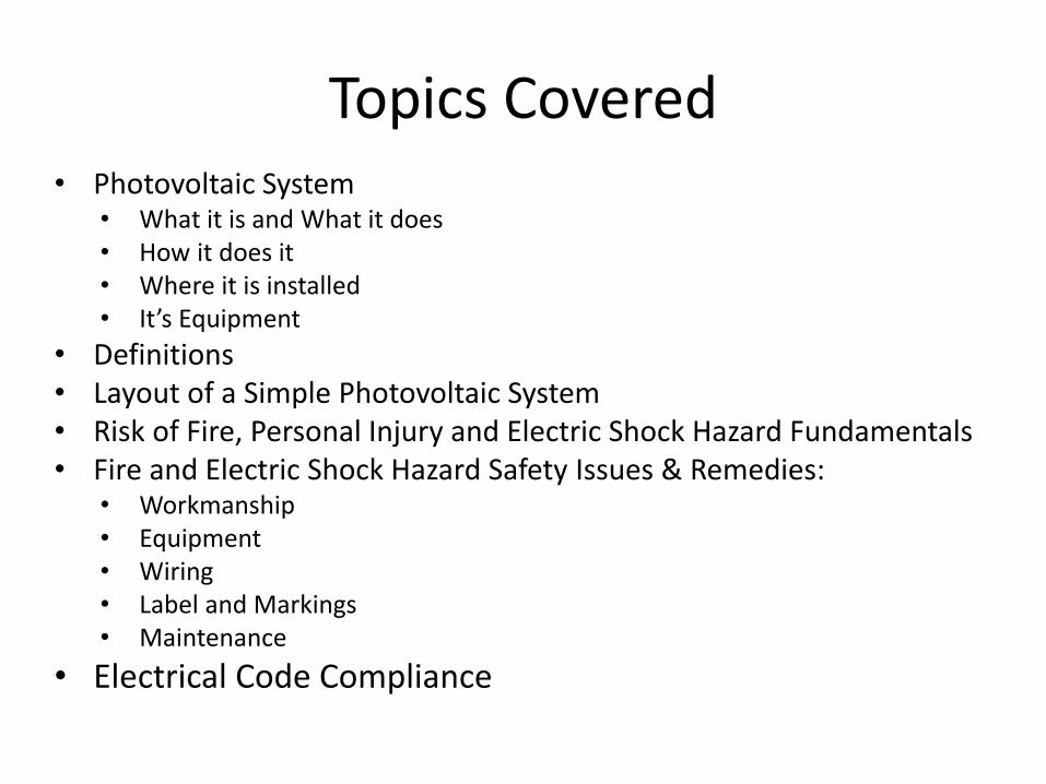
Topics Covered • Photovoltaic System
• What it is and What it does • How it does it • Where it is installed • It’s Equipment
• Definitions • Layout of a Simple Photovoltaic System • Risk of Fire, Personal Injury and Electric Shock Hazard Fundamentals • Fire and Electric Shock Hazard Safety Issues & Remedies:
• Workmanship • Equipment • Wiring • Label and Markings • Maintenance
• Electrical Code Compliance
Photovoltaic System – What, How, and Where
• Photovoltaic systems convert renewable solar energy into useable electric energy.
• For example, a solar panel exposed to Sunlight will generate direct current and voltage that can supply building loads (i.e., lighting, appliances, etc.) in lieu of utility power.
• In order to get good sun exposure, solar modules/panels are typically installed on roofs, but they may also be installed on the ground (i.e., mega power systems), on poles or trellises in parking lots, and even recently, on building walls.
Photovoltaic System - Equipment
• A photovoltaic solar system typically consist of the following equipment: – Modules – Inverter(s) – Combiner(s) – Disconnecting Means (i.e., switches or disconnects) – Overcurrent Protective Devices (i.e., fuses or circuit breakers) – Conductors (or Cables) – Connectors – Raceways – Load Center (s) – Equipment and System Ground – A Utility Meter
Definitions • Inverter – Equipment used to change voltage level or waveform, or both, of
electrical energy. They may be referred to as a “Power Conditioning Unit” or a “Power Conversion System”. This equipment changes dc input to an ac output.
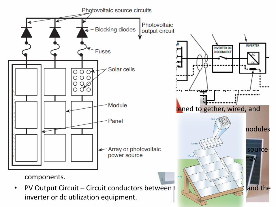
• Module – A complete, environmentally protected unit consisting of solar cells, optics, and other components, exclusive of tracker, designed to generate dc power when exposed to sunlight.
• Panel - A collection of modules mechanically fastened to gether, wired, and designed to provide a field-installable unit.
• Photovoltaic (PV) Source Circuit – Circuits between modules and from modules to the common connection point(s) (i.e., Combiner) of the dc system.
• Combiner – A box intended to combine together parallel wires from PV source circuits into a larger wire commonly referred to as PV output circuit. It may incorporate overcurrent protective devices, disconnects and other components.
• PV Output Circuit – Circuit conductors between the PV source circuit(s) and the inverter or dc utilization equipment.
Definitions Continued…
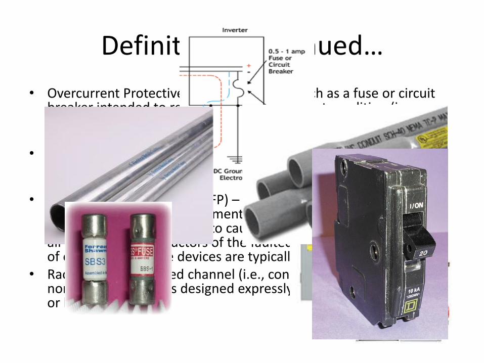
• Overcurrent Protective Device – A device such as a fuse or circuit breaker intended to respond to an overcurrent condition (i.e., overload, short circuit, or ground fault) in a circuit and de-energize the circuit upon activation.
• Disconnecting Means – A device, or group of devices, or other means by which the conductors or equipment can be disconnected from their source of supply.
• Ground-Fault Protection (GFP) – A system or device intended to provide protection of equipment from damaging line-to-ground fault currents by operating to cause a disconnecting means to open all ungrounded conductors of the faulted circuit. The current level of operation of these devices are typically above 30 ma.
• Raceway - An enclosed channel (i.e., conduit) of metal or nonmetallic materials designed expressly for holding wires, cables, or bus bars.
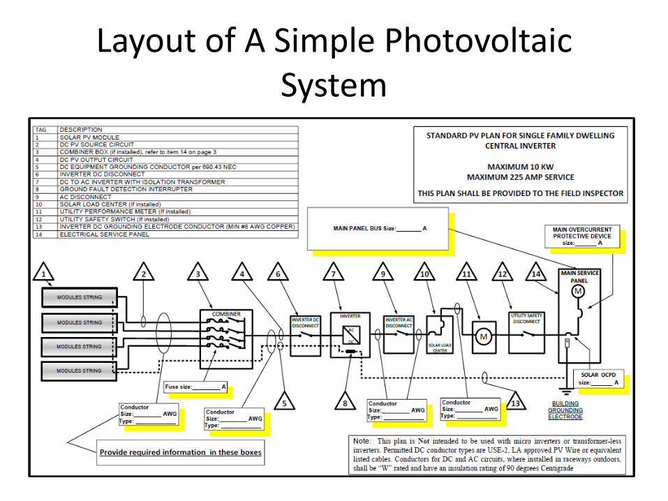
Layout of A Simple Photovoltaic System
Fire, Personal Injury and Electric Shock Hazard Fundamentals
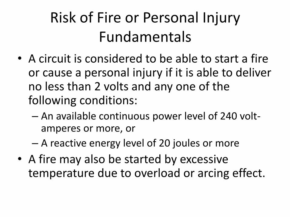
Risk of Fire or Personal Injury Fundamentals
• A circuit is considered to be able to start a fire or cause a personal injury if it is able to deliver no less than 2 volts and any one of the following conditions: – An available continuous power level of 240 volt-
amperes or more, or
– A reactive energy level of 20 joules or more
• A fire may also be started by excessive temperature due to overload or arcing effect.
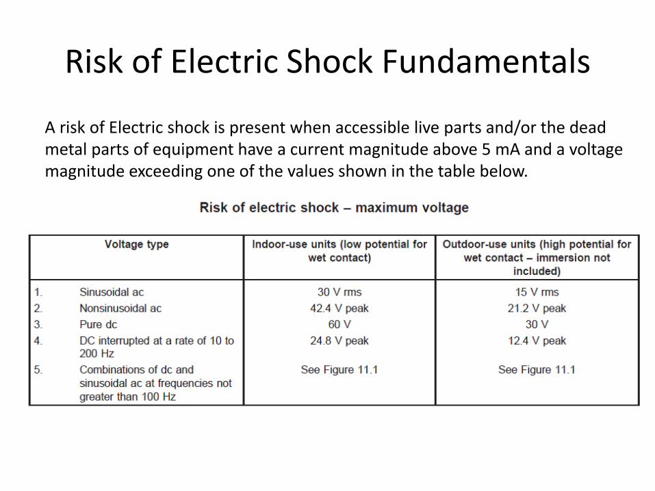
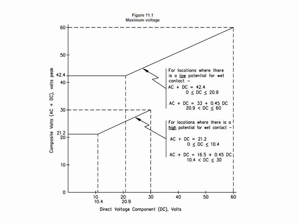
Risk of Electric Shock Fundamentals
A risk of Electric shock is present when accessible live parts and/or the dead metal parts of equipment have a current magnitude above 5 mA and a voltage magnitude exceeding one of the values shown in the table below.
Fire and Electric Shock Hazard Safety Issues
Type of Failures and Their Remedies
• Human and Workmanship
• Equipment
• Wiring
• Labels and Marking
• Maintenance

An Example of Human Failure
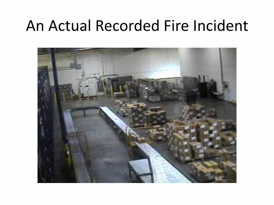
An Actual Recorded Fire Incident
An Example of Workmanship Failure
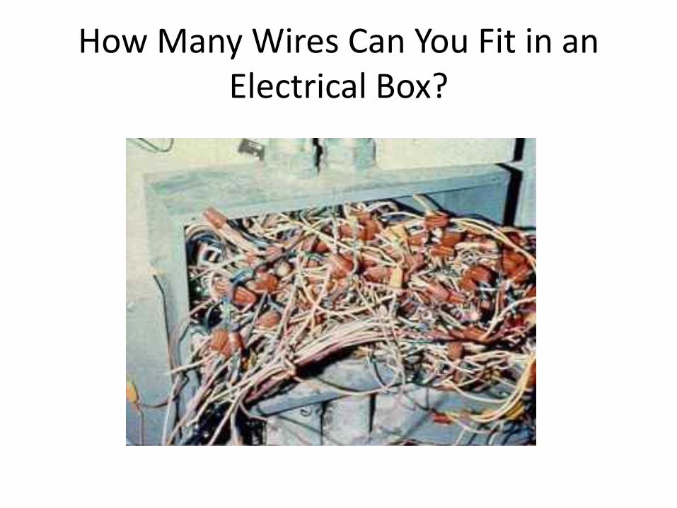
How Many Wires Can You Fit in an Electrical Box?
Human and Workmanship Remedies
• The installer should be a Contractor licensed by the State of California to perform such a work (i.e., B, C 10, C46, etc.).
• Follow equipment listing installation instructions.
• Comply with the Electrical Code.
• ANSI/NECA 1-2006, Standard Practice for Good Workmanship in Electrical Contracting, Is one example of the many ANSI standards that describe ‘‘neat and workmanlike’’ installations.
Equipment Failures
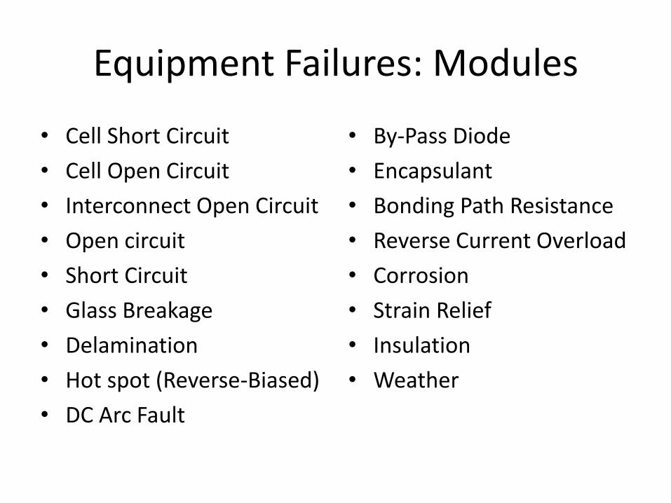
Equipment Failures: Modules
• Cell Short Circuit
• Cell Open Circuit
• Interconnect Open Circuit
• Open circuit
• Short Circuit
• Glass Breakage
• Delamination
• Hot spot (Reverse-Biased)
• DC Arc Fault
• By-Pass Diode
• Encapsulant
• Bonding Path Resistance
• Reverse Current Overload
• Corrosion
• Strain Relief
• Insulation
• Weather
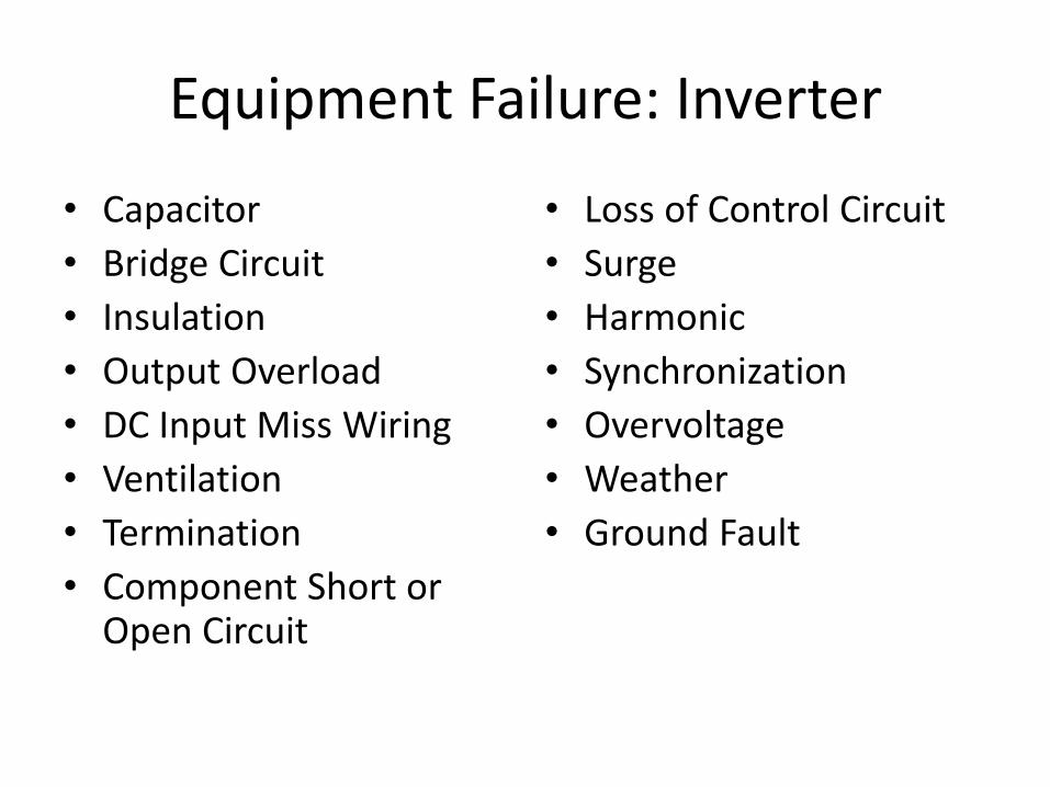
Equipment Failure: Inverter
• Capacitor
• Bridge Circuit
• Insulation
• Output Overload
• DC Input Miss Wiring
• Ventilation
• Termination
• Component Short or Open Circuit
• Loss of Control Circuit
• Surge
• Harmonic
• Synchronization
• Overvoltage
• Weather
• Ground Fault
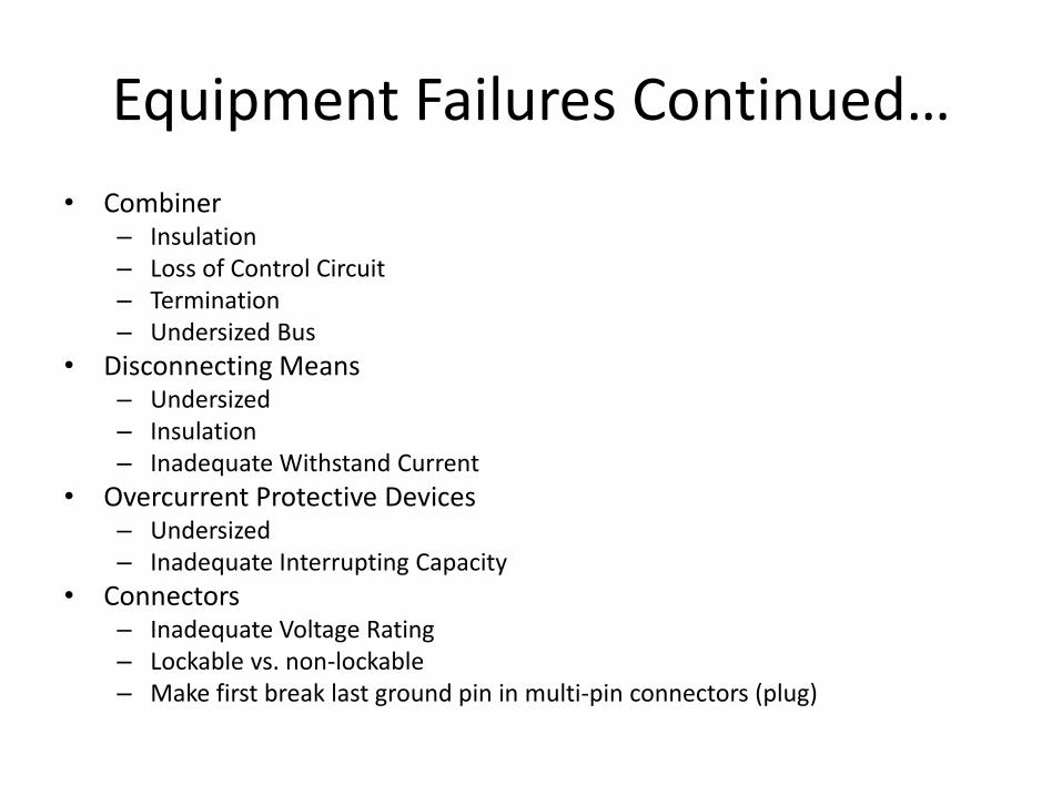
Equipment Failures Continued…
• Combiner – Insulation – Loss of Control Circuit – Termination – Undersized Bus
• Disconnecting Means – Undersized – Insulation – Inadequate Withstand Current
• Overcurrent Protective Devices – Undersized – Inadequate Interrupting Capacity
• Connectors – Inadequate Voltage Rating – Lockable vs. non-lockable – Make first break last ground pin in multi-pin connectors (plug)
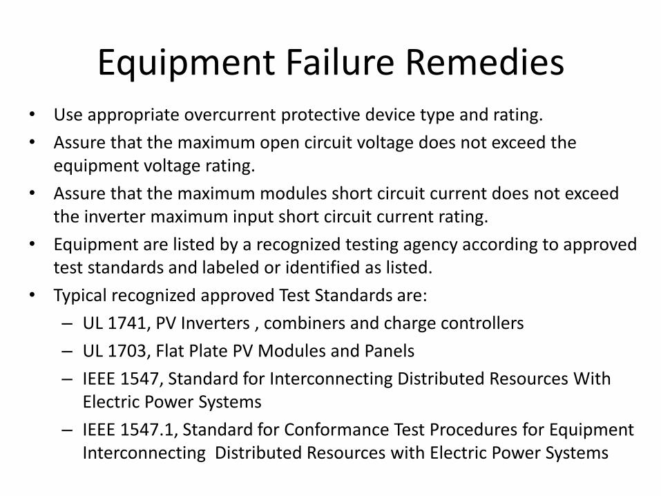
Equipment Failure Remedies • Use appropriate overcurrent protective device type and rating.
• Assure that the maximum open circuit voltage does not exceed the equipment voltage rating.
• Assure that the maximum modules short circuit current does not exceed the inverter maximum input short circuit current rating.
• Equipment are listed by a recognized testing agency according to approved test standards and labeled or identified as listed.
• Typical recognized approved Test Standards are:
– UL 1741, PV Inverters , combiners and charge controllers
– UL 1703, Flat Plate PV Modules and Panels
– IEEE 1547, Standard for Interconnecting Distributed Resources With Electric Power Systems
– IEEE 1547.1, Standard for Conformance Test Procedures for Equipment Interconnecting Distributed Resources with Electric Power Systems
Equipment Failures Remedies Continued…
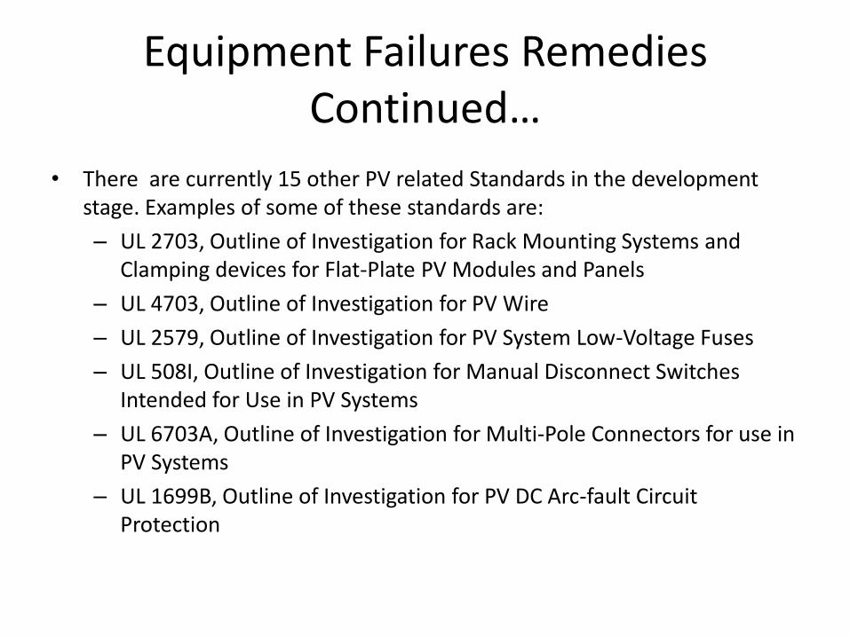
• There are currently 15 other PV related Standards in the development stage. Examples of some of these standards are:
– UL 2703, Outline of Investigation for Rack Mounting Systems and Clamping devices for Flat-Plate PV Modules and Panels
– UL 4703, Outline of Investigation for PV Wire
– UL 2579, Outline of Investigation for PV System Low-Voltage Fuses
– UL 508I, Outline of Investigation for Manual Disconnect Switches Intended for Use in PV Systems
– UL 6703A, Outline of Investigation for Multi-Pole Connectors for use in PV Systems
– UL 1699B, Outline of Investigation for PV DC Arc-fault Circuit Protection
Wiring Failures
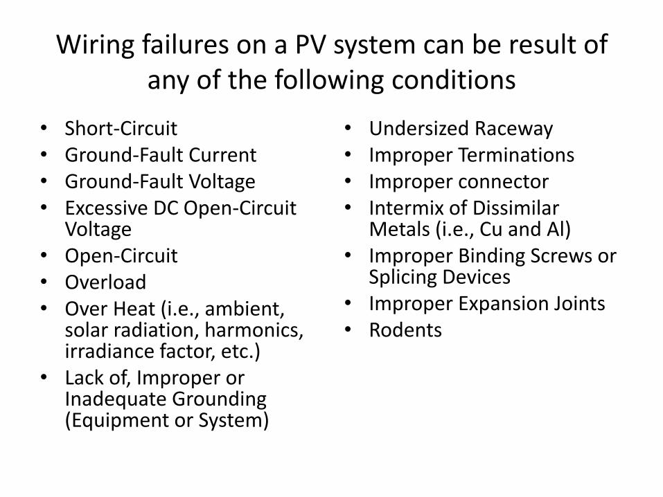
Wiring failures on a PV system can be result of any of the following conditions
• Short-Circuit • Ground-Fault Current • Ground-Fault Voltage • Excessive DC Open-Circuit
Voltage • Open-Circuit • Overload • Over Heat (i.e., ambient,
solar radiation, harmonics, irradiance factor, etc.)
• Lack of, Improper or Inadequate Grounding (Equipment or System)
• Undersized Raceway • Improper Terminations • Improper connector • Intermix of Dissimilar
Metals (i.e., Cu and Al) • Improper Binding Screws or
Splicing Devices • Improper Expansion Joints • Rodents
An Example Wiring Failure
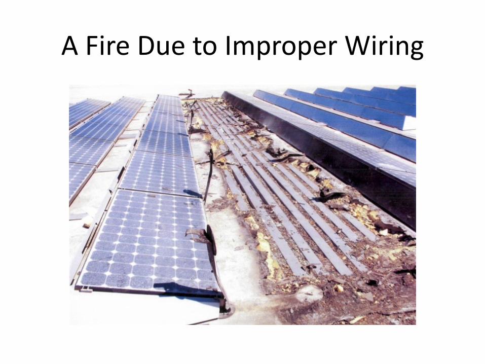
A Fire Due to Improper Wiring
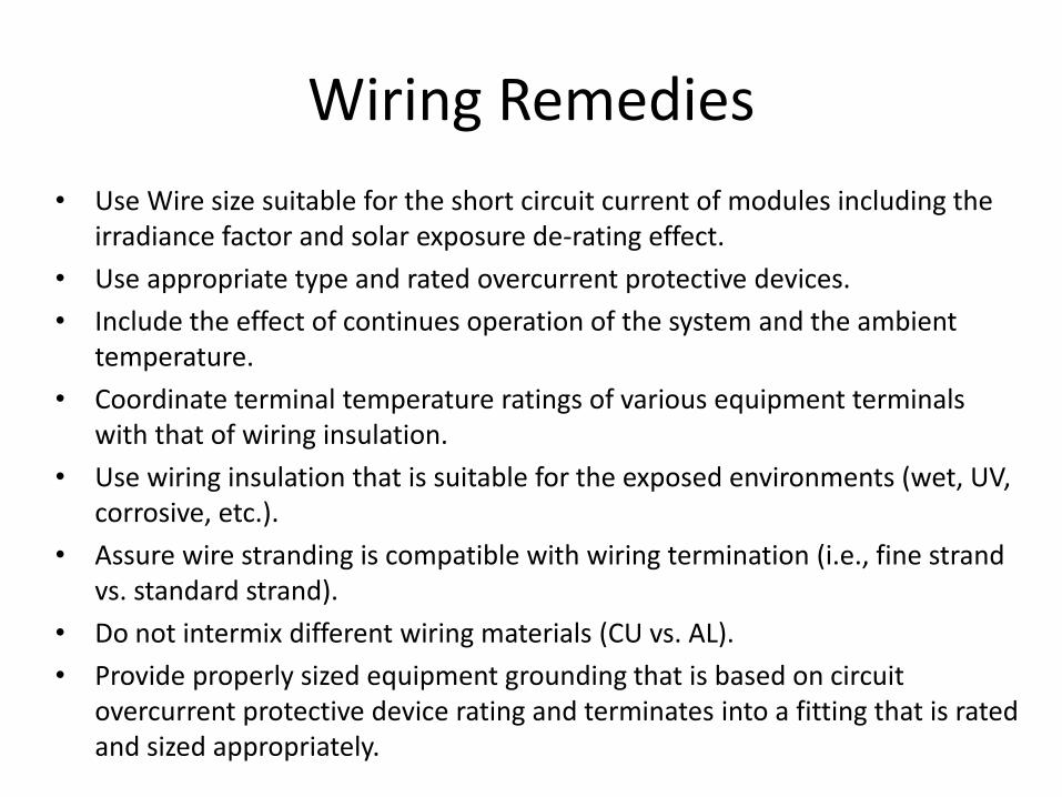
Wiring Remedies
• Use Wire size suitable for the short circuit current of modules including the irradiance factor and solar exposure de-rating effect.
• Use appropriate type and rated overcurrent protective devices.
• Include the effect of continues operation of the system and the ambient temperature.
• Coordinate terminal temperature ratings of various equipment terminals with that of wiring insulation.
• Use wiring insulation that is suitable for the exposed environments (wet, UV, corrosive, etc.).
• Assure wire stranding is compatible with wiring termination (i.e., fine strand vs. standard strand).
• Do not intermix different wiring materials (CU vs. AL).
• Provide properly sized equipment grounding that is based on circuit overcurrent protective device rating and terminates into a fitting that is rated and sized appropriately.
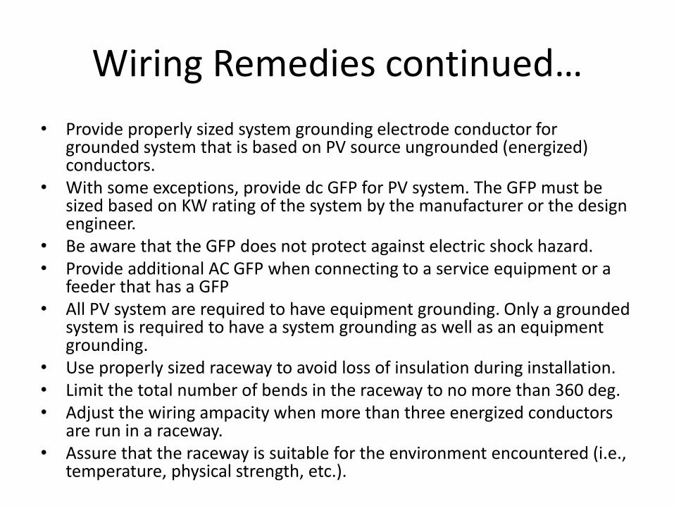
Wiring Remedies continued…
• Provide properly sized system grounding electrode conductor for grounded system that is based on PV source ungrounded (energized) conductors.
• With some exceptions, provide dc GFP for PV system. The GFP must be sized based on KW rating of the system by the manufacturer or the design engineer.
• Be aware that the GFP does not protect against electric shock hazard. • Provide additional AC GFP when connecting to a service equipment or a
feeder that has a GFP • All PV system are required to have equipment grounding. Only a grounded
system is required to have a system grounding as well as an equipment grounding.
• Use properly sized raceway to avoid loss of insulation during installation. • Limit the total number of bends in the raceway to no more than 360 deg. • Adjust the wiring ampacity when more than three energized conductors
are run in a raceway. • Assure that the raceway is suitable for the environment encountered (i.e.,
temperature, physical strength, etc.).
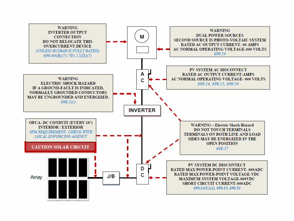
Labels and Markings
• Due to inherent hazard of PV system and need for proper maintenance, numerous markings are required by listed products and the electrical code.
• Labels and Markings may provide information on the components of the system, such as Module, PV system operating condition, Identifying a component, Or a warning referring to possible shock hazard (i.e., upon activation of GFP in a PV system or an open disconnect with both terminals still energized, etc.), Overvoltage, device ratings, Presence of all sources, etc.
Typical Electrical Code and State Fire Marshall (SFM) Required Markings in a
PV System
Maintenance
• PV system would require different maintenance during it’s life time.
• Disconnecting Means are required to be installed at various PV equipment (i.e., inverters) to accommodate their removal when required for maintenance or replacement.
• PV modules needs to be cleaned of dust to maintain it’s operating efficiency.
Electrical Code Compliance
• Installations in the State of California are required to comply with the 2010 California Electrical Code that is based on 2008 National Electrical Code.
• Article 690 of the Electrical Code specifically applies to Solar Photovoltaic Systems.
• Wherever the requirements of other articles of the code and Article 690 differ, the requirements of Article 690 apply.
• Other Articles and Sections of the Code (i.e., Article 240, and Sections 705.14, .16, .32, .143) as referred by article 690 also apply.

The End