Embed Size (px)
Citation preview

WFC-M Series Specifications
www.maya-airconditioning.com
WFC - M Series
Hot water fired single effect
absorption chiller
1 Specifications
WFC-M100 Version 0.17

WFC-MC Series Specifications
1
Contents
Page
1. Specifications 1.1 Model Designation....................................................... 2
1.2 Multiple Module........................................................... 2
1.3 Specification Table (WFC-M100)................................ 3
1.4 External Dimensions (WFC-M100) ............................ 4
2. Performance Characteristics 2.1 Cooling Performance ( WFC-M100)............................ 5
2.2 De-rating factor (WFC-M100) ..................................... 6
2.3 Noise Criteria (WFC-M100) ........................................ 7
3. Principle & Structure 3.1 General.......................................................................... 8
3.2 Cooling Cycle............................................................... 8
3.3 Heat Balance................................................................. 9
4. Component Identification & Function 4.1 Chiller assembly (WFC-M100) ................................... 10
4.2 Component Description................................................ 12

WFC-MC Series Specifications
2
1. Specification
1.1 Model Designation
Example
W F C - M 100
Water Fired Chiller
Series
Cooling Capacity RT
1.2 Multiple Module Combination
Model Increment
RT
Range
RT Note
WFC-M100 100 100 to 500 Cooling only
WFC-MC Series Specifications
3
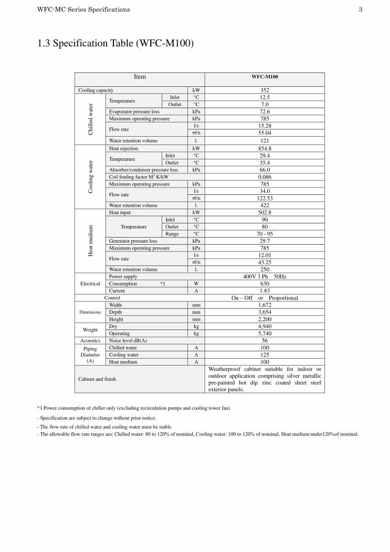
1.3 Specification Table (WFC-M100)
Item
WFC-M100
Cooling capacity kW 352 C
hil
led w
ater
Temperature Inlet °C 12.5
Outlet °C 7.0
Evaporator pressure loss kPa 72.6
Maximum operating pressure kPa 785
Flow rate l/s 15.28
㎥/h 55.04
Water retention volume l. 121
Cooli
ng w
ater
Heat rejection kW 854.8
Temperature Inlet °C 29.4
Outlet °C 35.4
Absorber/condenser pressure loss kPa 66.0
Coil fouling factor M2 K/kW 0.086
Maximum operating pressure kPa 785
Flow rate l/s 34.0
㎥/h 122.53
Water retention volume l. 422
Hea
t m
ediu
m
Heat input kW 502.8
Temperature
Inlet °C 90
Outlet °C 80
Range °C 70 - 95
Generator pressure loss kPa 29.7
Maximum operating pressure kPa 785
Flow rate l/s 12.01
㎥/h 43.25
Water retention volume l. 250
Electrical
Power supply 400V 3 Ph 50Hz
Consumption *1 W 630
Current A 1.83
Control On – Off or Proportional
Dimensions
Width mm 1,672
Depth mm 3,654
Height mm 2,200
Weight Dry kg 4,940
Operating kg 5,740
Acoustics Noise level dB(A) 56
Piping
Diameter
(A)
Chilled water A 100
Cooling water A 125
Heat medium A 100
Cabinet and finish
Weatherproof cabinet suitable for indoor or
outdoor application comprising silver metallic
pre-painted hot dip zinc coated sheet steel
exterior panels.
*1.Power consumption of chiller only (excluding recirculation pumps and cooling tower fan)
- Specification are subject to change without prior notice.
- The flow rate of chilled water and cooling water must be stable.
- The allowable flow rate ranges are: Chilled water: 80 to 120% of nominal, Cooling water: 100 to 120% of nominal, Heat medium:under120%of nominal.
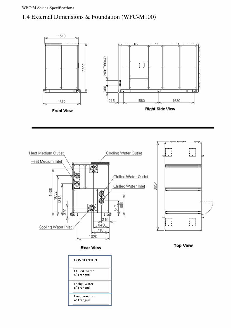
WFC-M Series Specifications
1.4 External Dimensions & Foundation (WFC-M100)

WFC-M Series Specifications 5
2.Performance Characteristics
2.1 Cooling Performance WFC-M100 (typical)

WFC-M Series Specifications 6
Note: All other parameters of flow and temperature are considered standard.
2.2 De-rating factor (WFC-M100)

WFC-M Series Specifications 7
2.3 Noise Criteria (WFC-M100)
NC curves

WFC-M Series Specifications 8
3. Principle & Structure
3.1 General
WFC-M100 is an absorption chiller (cooling only) which can reduce energy consumption for
air-conditioning by utilizing low temperature (70-95degC) hot water, such as CHP cooling
water, factory waste heat, and solar water heaters. The WFC-M100 can connect 5 units,
adapt up to 500RT cooling capacity.
3.2 Cooling Cycle.
Referring to the schematic of the cooling cycle as shown in figure1, lithium bromide solution
(Dilute Solution) is pumped to the generator (GE) by the solution pump (SP) where it is
heated to boiling point by the circulating heat medium. Refrigerant vapor (water vapor) is
liberated from solution and flows to the condenser (CON) where it is condensed to a liquid
state by rejection of heat to the cooling water from the cooling tower circulating through the
condenser coil.
Because partial separation of the lithium bromide and the water in solution has occurred in the
process of boiling in the (GE), an increase in concentration takes place and the resultant
solution is termed (Concentrate Solution). Accordingly, the concentrate solution flows from
(GE) to the heat exchanger (HE), imparting heat to the dilute solution, before arriving at the
absorber (ABS) to flow over the surface of the absorber coil.
Since cooling water from the cooling tower is circulating through the absorber coil, a
comparatively low vapor pressure is created due to the concentration of the lithium solution,
and this is the environment which refrigerant liquid from the condenser encounters as it flows
over the coil in the evaporator (EVA). The concentrated solution absorbs refrigerant vapor
from the evaporator as the liquid refrigerant changes phase deriving heat of vaporization from
the chilled water circulating through the evaporator coil. This results in the production of
chilled water.
The concentrate solution returns to a diluted state as refrigerant vapor is absorbed. In its
relatively cool condition, it is collected in the (ABS)/(EVA) sump and thereafter forced by
(SP) through the (HE) collecting heat from the concentrate solution before returning to the
(GE) for boiling again to repeat the cycle.

WFC-M Series Specifications 9
3.3 Heat Balance for WFC-M100 (Cooing Cycle)
GE: Generator EVA: Evaporator
ABS: Absorber CON: Condenser
SV1: Solution valve CPV: Concentrated valve
SP: Solution pump RPV: Refrigerant valve
HE: Heat exchanger GT: Gas Tank
Fig 1
Heat Medium Inlet
Heat Medium Outlet
Chilled Water Outlet
Chilled Water Inlet
Cooling Water Outlet
Cooling Water Inlet
Cooling Cycle

WFC-M Series Specifications 10
4. Component Identification & Function
4.1 Chiller Assembly (WFC-M100)
(Left View)
14.GT gas service valve
13. Non-condensable
gas storage tank (GT)
8. Freeze prevention
valve (SV1)
19. LT thermostat (LT)
10. Solution pump (SP) 4. Refrigerant proportional
valve (RPV)
15. Absorber service valve
27.. Control box (CB)
18. Flow witch (FS1)
16.Dilute solution
sampling valve
17.Concentrated solution
sampling valve
(Right view)
1.GE
6.ABS
2.CON
5.EVA
7.Concentrated
proportional valve (CPV)
9.Heat exchanger (HE)
12.Non-condensable
gas separator
20.CND thermostat
(CND)
11.Ejector

WFC-M Series Specifications 11
(Rear View)
Cooling water outlet
Cooling water inlet
Heat medium outlet
Heat medium inlet
Chilled water outlet
24:CTO thermostat
23. CTI thermostat
Chilled water inlet
25. HWTI thermostat
26.HWTO thermostat
22. WTO thermostat
21. WTI thermostat
6. ABS
1.GE
2.CON
5..EVA

WFC-M Series Specifications 12
4.2 Component Description
Dilute Solution
Concentrated Solution
Refrigerant Vapor
Refrigerant Liquid
Chilled Water Cooling Water
Heat Medium
① ②
③
④
⑤ ⑥
⑦
⑧
⑨ ⑩
⑪
RST
⑫
⑬ ⑭
⑯
⑰
⑮ ⑱
⑲22
⑳
21
23
24
25
26

WFC-M Series Specifications 13
No. Component Description
1 Generator (GE) Boils dilute LiBr solution to separate refrigerant from the
absorbent
2 Condenser (CON) Condenses refrigerant vapor to provide liquid refrigerant.
3 Refrigerant storage
(RST)
For accumulating liquid refrigerant resulting from the function of
the RPV valve.(Inside CON)
4
Refrigerant
proportion valve
(RPV)
Electromagnetic proportional valve for controlling the storage of
liquid refrigerant.
5
Evaporator (EVA) Heat of evaporation or condensation from the refrigerant is
extracted from, or transferred to, the water flowing through the
EVA coil
6
Absorber (ABS) As refrigerant vapor is absorbed by the LiBr solution, heat of
absorption is transferred to the cooling water flowing through the
ABS coil.
7
Concentrated
proportional control
valve (CPV)
n the event the evaporator temperature falls, CPV valve will
open to allow a proportion of the concentrated LiBr solution
flowing to the ABS to bypass the tube. When the evaporator
temperature increases, CPV will close.
8
Freeze prevention
Valve(SV1)
If the operation of SV9 does not arrest the fall in temperature of
the EVA, SV1 valve will open at 1°C to allow dilute solution to
enter the evaporator.
9 Heat exchanger
(HE)
Heat exchange between the cool dilute and hot concentrate LiBr
solution is facilitated by HE
10 Solution pump (SP) Dilute LiBr solution is transferred from the ABS to the GE by
the SP..
11
Ejector
Using pressured cooled dilute solution as a driving fluid to make
lower pressure than ABS to extract non-condensable gas. It is
also extractive in similar principle during heating.
12 Non-condensable
gas separator
Gases gathered by the auxiliary absorber are separated from
dilute solution and transported to the storage tank GT.
13
Non-condensable
gas storage
tank(GT)
GT retains non-condensable gases accumulating in the
absorption circuit.
14
Non-condensable
storage service
valve (A)
Removal of non-condensable gases from the GT is facilitated by
valve (A).
15 ABS service valve
(B)
Vacuum service of the ABS/EVA areas of the chiller is afforded
by valve (B)
16 Dilute solution
sampling valve
Dilute LiBr solution circuit is accessed by the dilute solution
service valve.
17
Concentrate
solution sampling
valve
Concentrate LiBr solution circuit is accessed by the concentrate
solution service valve.
18 Flow switch (FS1) If the chilled water flow rate falls to less than 80% of standard,
the operation of the chiller-heater will cease.
19 Thermostat (LT) Operation of the chiller is responsive to the EVA temperature
monitored by LT
20 Thermostat (CND) Condenser refrigerant temp., for judging coil scale formation
21 Thermostat (WTI) The chilled water outlet temperature is controlled by
22 Thermostat (WTO) The chilled water outlet temperature is controlled by WTO
23 Thermostat (CTI) The chiller operation is responsive to cooling water temperature
monitored by CTI
24 Thermostat (CTO) The chiller operation is responsive to cooling water temperature
monitored by CTO
25 Thermostat
(HWTI)
Operation of the chiller is responsive to the inlet heat medium
temperature monitored by HWTI
26 Thermostat
(HWTO)
Operation of the chiller is responsive to the inlet heat medium
temperature monitored by HWTO
27 Control box (CB) All operation of the chiller-heater and interface with external
controls is provided by the CB