Embed Size (px)
Citation preview
Journal of Mechanical Science and Technology 22 (2008) 2498~2508 www.springerlink.com/content/1738-494x
DOI 10.1007/s12206-008-0753-6
Journal of Mechanical Science and Technology
Wet surface heat transfer and pressure drop of aluminum parallel
flow heat exchangers at different inclination angles† Nae-Hyun Kim1,*, Do-Young Kim1 and Jun-Hyun Hwang2
1Department of Mechanical Engineering, University of Incheon 177 Dohwa-Dong, Nam-Gu, Incheon, 402-749, Korea 2LG Electronics 76 Seongsan-Dong, Changwon, Gyeongnam, 641-713, Korea
(Manuscript Received March 17, 2008; Revised July 17, 2008; Accepted July 31, 2008)
--------------------------------------------------------------------------------------------------------------------------------------------------------------------------------------------------------------------------------------------------------
Abstract The effect of inclination angle on the heat transfer and pressure drop characteristics of brazed aluminum heat ex-
changers was experimentally investigated under wet conditions. Three samples having different fin pitches (1.25, 1.5 and 2.0 mm) were tested. Results show that heat transfer coefficients are not affected by the inclination angle. However, friction factors increase as the inclination angle increases with negligible difference between the forward and backward inclination. The effect of fin pitch on the heat transfer coefficient and on the pressure drop is also discussed. Compari-son of the dry and wet surface heat transfer coefficients reveals that dry surface heat transfer coefficients are signifi-cantly larger than wet surface heat transfer coefficients. Possible explanation is provided by considering the condensate drainage pattern. The data are also compared with the existing correlation.
Keywords: Wet surface; Heat transfer coefficient; Pressure drop; Parallel flow; Inclination --------------------------------------------------------------------------------------------------------------------------------------------------------------------------------------------------------------------------------------------------------
1. Introduction
Fin-and-tube heat exchangers have been widely used as condensers or evaporators in household air-conditioning systems. In the forced convective heat transfer between air and refrigerant, the controlling thermal resistance is on the air-side. To improve the air-side performance, rigorous efforts have been made, which include the usage of high performance fins, small diameter tubes, etc. However, fin-and-tube heat exchangers have inherent shortcomings, such as the contact resistance between fins and tubes, the exis-tence of a low performance region behind tubes, etc. These short-comings may be overcome if fins and tubes are soldered, and low profile flat tubes with high performance fins are used. Brazed aluminum flat-tube heat exchangers with louver fins could be
the choice. Flat tube heat exchangers have been used as condensers of automotive air conditioning units for more than ten years, and they are replacing fin-and-tube condensers of residential air-conditioning units. The possibility of replacing the residential fin-and-tube heat exchangers by flat tube heat exchangers has been studied by Webb and Jung [1]. They showed that, for the same air-side thermal capacity, the flat-tube geometry requires less than half the heat ex-changer volume compared with the fin-and-tube counterpart. The advantage of flat-tube heat exchang-ers has further been studied by Webb and Lee [2]. They compared the thermal performance of flat tube condenser having 866 fins per meter with that of the fin-and-tube condenser having 7.0 mm round tubes and 1024 fins per meter. The flat tube condenser was shown to reduce the material up to 50%.
Evaporators of split-type air-conditioners are fre-quently installed in ceilings, because they provide good air flow distribution as well as saving of instal-lation space compared with conventional room-mounted ones. In the ceiling-mounted configuration,
†This paper was recommended for publication in revised form by Associate Editor Man-Yeong Ha
*Corresponding author. Tel.: +82 32 770 8420, Fax.: +82 32 770 8410 E-mail address: [email protected] © KSME & Springer 2008
N.-H. Kim et al. / Journal of Mechanical Science and Technology 22 (2008) 2498~2508 2499
evaporators are usually installed at some inclined angle due to the limited space in ceilings. Usage of high performance flat tube heat exchangers may fur-ther reduce the height of ceiling-mounted evaporators. However, the heat transfer performance can be greatly affected by the condensate that forms on the air-side louvered surface. The condensate may disrupt the air flow through the evaporator and affect the heat transfer performance.
The literature survey reveals that significant ad-vances have been made in the understanding of flow and heat transfer characteristics of louvered surfaces under dry conditions. Davenport [3] showed that, through a flow visualization study, the flow did not pass through louvers at low Reynolds numbers. At high Reynolds numbers, however, the flow became nearly parallel to louvers. Achaichia and Cowell [4] further confirmed, through heat transfer tests on flat tube heat exchangers having louvered plate fins, that the heat transfer coefficients approached those of duct flow at sufficiently low Reynolds numbers. At high Reynolds numbers, the heat transfer coefficients were parallel to those of the laminar boundary layer for a flat plate. Two types of flow were identified within the louvered plate fin array: duct directed flow and louver directed flow. The amount of either flow de-pended on the louver geometry such as fin pitch, lou-ver pitch, louver angle as well as the Reynolds num-ber. Following the pioneering study by Davenport [3], many investigations have been made on the air-side heat transfer and pressure drop characteristics of lou-ver fin – flat tube heat exchangers both experimen-tally [1, 5-9] or numerically [10-16]. Those studies generally confirmed the findings by Davenport [3] and Achaichia and Cowell [4].
Compared to the significant number of studies con-ducted under dry conditions, very limted investiga-tions have been performed under wet conditions. McLaughlin and Webb [17] identified two different types condensate formation on louvered surfaces: one formed between louvers (louver bridging), and the other formed between fins (fin bridging). It was ob-served that louver bridging increased as the louver pitch decreased. Fin bridging increased as the fin pitch decreased. In a subsquent heat transfer study, McLaughlin and Webb [18] reported that, for a sam-ple having rather short louver pitch (1.1 mm), a sig-nificant decrease of heat transfer and pressure drop occurred under wet conditions compared to dry con-ditions, while much smaller change was observed for
the sample having 1.3 mm louver pitch. It was specu-lated that for small louver pitch, condensate bridged louvers and prohibited the formation of louver-directed flow, and subsquently heat transfer and pres-sure drop decreased. A hydrophilic coating increased the heat transfer by 25%, but showed insignificant impact on pressure drop. It was speculated that the coating helped drain the condensate both in louvers and in fins, and the increased pressure drop due to reduced louver bridging was compensated by the decreased pressure drop due to reduced fin bridging. Different from McLaughlin and Webb [18], Kim and Bullard [19] reported increased pressure drop under wet conditions. It is speculated that louver bridging was not present in their sample due to large louver pitch (1.7 mm), and the increased pressure drop is due to the condensate formed between fins.
There are some publications on the effect of incli-nation angle on the heat transfer and pressure drop characteistics of heat exchangers. However, most of them are for bare tube banks, high-fin tube banks and conventional finned tube heat exchangers [20-22]. Literature reveals three studies for the the effect of inclination angle of louvered surface heat exchangers. Osada et al. [23] studied the effect of inclination on the wet surface heat transfer and pressure drop of louvered surface in a single fin column test section. It was reported that forward inclination improved the thermal performance. Kim et al. [24] studied the ef-fect of inclination angle on wet surface heat transfer and pressure drop of a brazed aluminum heat ex-changer having 20 mm flow depth, 1.4 mm fin ptich, 1.7 mm louver pitch and 27 degree louver angle. Both forward and backward inclination was investigated. They reported that heat transfer coefficients were relatively insensitive to the inclination angle, while presure drops increased as the inclination angle in-creased. Kim et al. [25] extended the study to the effect of inlet humdity.
The literature survey reveals that the effect of incli-nation on the heat transfer and pressure drop of lou-vered surfaces is very limited. Only one study by Kim et al. [24] is relevant. However, they tested only one sampe having 20 mm flow depth, 1.4 mm fin ptich, 1.7 mm louver pitch and 27 degree louver angle. In this study, three samples having different fin pitches (1.25, 1.5, 2.0 mm) were tested. The samples had relatively deep flow depth (34 mm) and small louver pitch (0.9 mm). The louver angle was 22 degrees. Both forward and backward inclination (-60o
2500 N.-H. Kim et al. / Journal of Mechanical Science and Technology 22 (2008) 2498~2508
β≤ ≤ 60o) were investigated. 2. Experiment
2.1 Heat exchanger samples
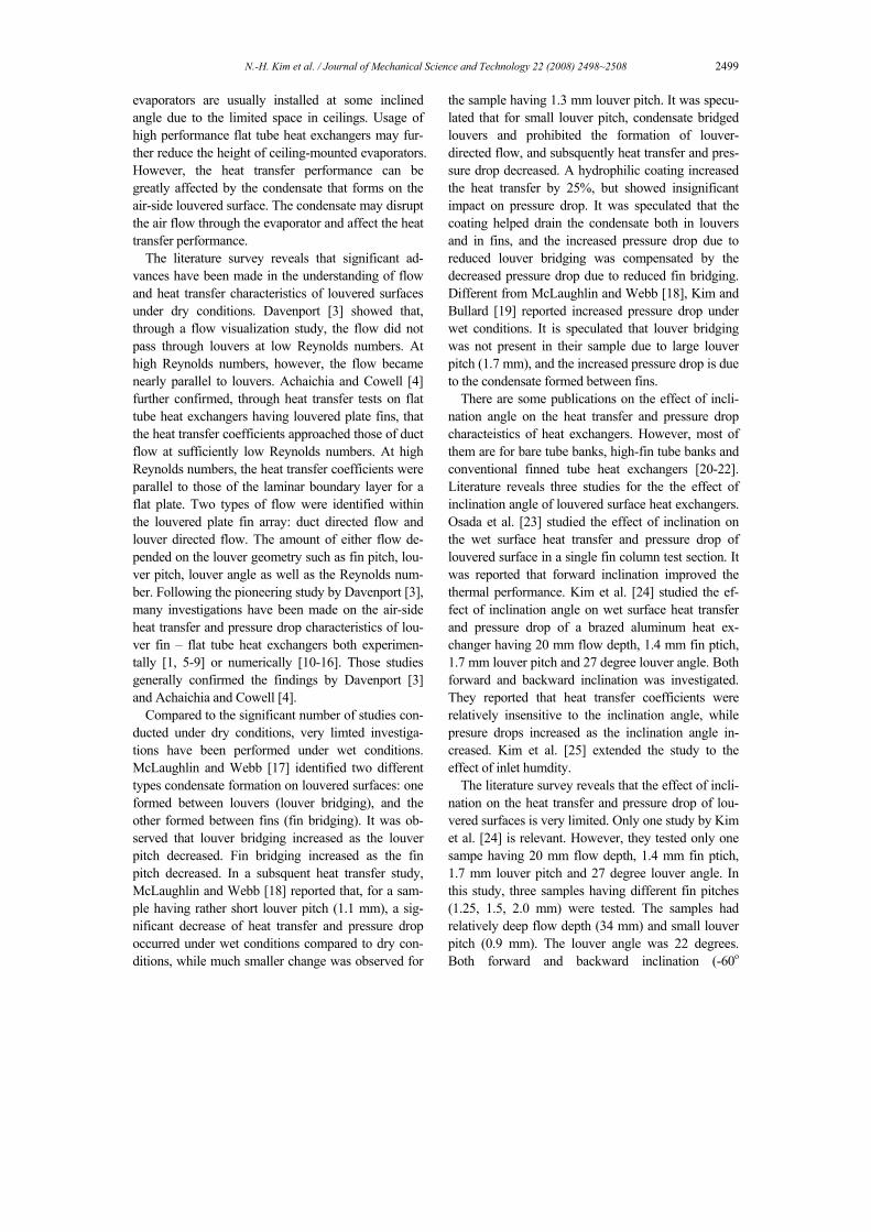
Three heat exchangers having different fin pitches (1.25 mm, 1.5 mm, 2.0 mm) were tested. The samples consisted of 37 steps of louver fins brazed to flat tubes as illustrated in Fig. 1. The height and width of the samples were 254 mm and 385 mm, respectively. Hydrophilic coating was not applied to the fin. The tube-side was circuited in a serpentine fashion with four tubes per pass. With this circuitry, tube-side flow was maintained turbulent. Maintaining turbulent flow in the tube-side is important because the tube-side
Table 1. Geometric dimensions of test samples.
Sample FD (mm)
α (deg)
FP (mm)
LP (mm)
Ll (mm)
H (mm)
TP (mm)
S1
(mm)S2
(mm)
1 2 3
34 34 34
22 22 22
1.25 1.5 2.0
0.9 0.9 0.9
6.8 6.8 6.8
8.56 8.56 8.56
10.4610.4610.46
1.11.11.1
1.241.241.24
Fig. 1. Schematic drawing of the sample heat exchanger.
Fig. 2. Geometric details of the fin and tube.
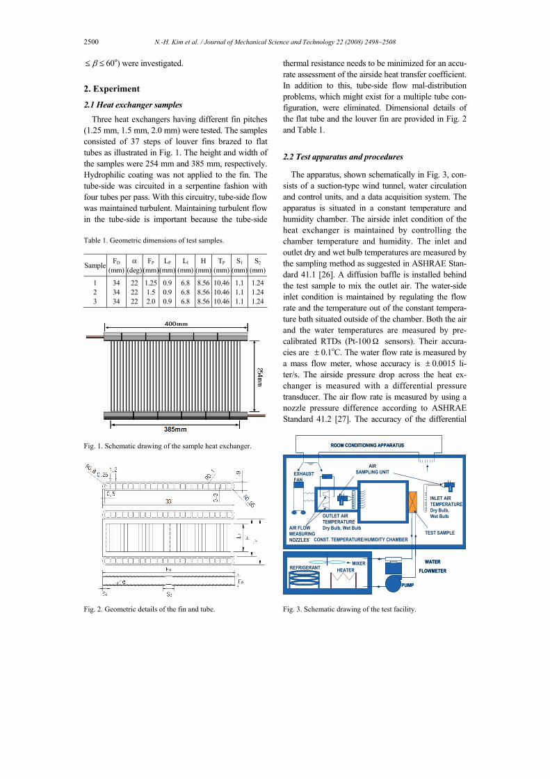
thermal resistance needs to be minimized for an accu-rate assessment of the airside heat transfer coefficient. In addition to this, tube-side flow mal-distribution problems, which might exist for a multiple tube con-figuration, were eliminated. Dimensional details of the flat tube and the louver fin are provided in Fig. 2 and Table 1.
2.2 Test apparatus and procedures
The apparatus, shown schematically in Fig. 3, con-sists of a suction-type wind tunnel, water circulation and control units, and a data acquisition system. The apparatus is situated in a constant temperature and humidity chamber. The airside inlet condition of the heat exchanger is maintained by controlling the chamber temperature and humidity. The inlet and outlet dry and wet bulb temperatures are measured by the sampling method as suggested in ASHRAE Stan-dard 41.1 [26]. A diffusion baffle is installed behind the test sample to mix the outlet air. The water-side inlet condition is maintained by regulating the flow rate and the temperature out of the constant tempera-ture bath situated outside of the chamber. Both the air and the water temperatures are measured by pre-calibrated RTDs (Pt-100Ω sensors). Their accura-cies are ± 0.1oC. The water flow rate is measured by a mass flow meter, whose accuracy is ± 0.0015 li-ter/s. The airside pressure drop across the heat ex-changer is measured with a differential pressure transducer. The air flow rate is measured by using a nozzle pressure difference according to ASHRAE Standard 41.2 [27]. The accuracy of the differential
ROOM CONDITIONING APPARATUS
OUTLET AIRTEMPERATUREDry Bulb, Wet Bulb
INLET AIRTEMPERATUREDry Bulb, Wet Bulb
AIRSAMPLING UNITEXHAUST
FAN
CONST. TEMPERATURE/HUMIDITY CHAMBER
∆P
TEST SAMPLE
MIXERREFRIGERANT HEATER
WATER
FLOWMETER
PUMP
AIR FLOWMEASURINGNOZZLES`
ROOM CONDITIONING APPARATUS
OUTLET AIRTEMPERATUREDry Bulb, Wet Bulb
INLET AIRTEMPERATUREDry Bulb, Wet Bulb
AIRSAMPLING UNITEXHAUST
FAN
CONST. TEMPERATURE/HUMIDITY CHAMBER
∆P
TEST SAMPLE
MIXERREFRIGERANT HEATER
WATER
FLOWMETER
PUMP
AIR FLOWMEASURINGNOZZLES`
Fig. 3. Schematic drawing of the test facility.

N.-H. Kim et al. / Journal of Mechanical Science and Technology 22 (2008) 2498~2508 2501
Fig. 4. Sketch showing the installation of the sample.
pressure transducers is ± 1.0 Pa. The wind tunnel is equipped with multiple nozzles, and an appropriate one is selected depending on the air velocity. The heat exchanger sample was installed in front of the wind tunnel by using a rectangular duct as shown in Fig. 4. The duct was made of acryl plate for visualization of the condensate drainage from the sample. The duct height was determined from the inclination angle of the sample, and duct width was the same as the width of the sample. The duct length was 270 mm and 360 mm for ± 30o and ± 60o inclination, respectively. For 0o inclination, the sample was installed right at the inlet of the wind tunnel without a duct.
During the experiment, the water inlet temperature was held at 5.5oC. The chamber temperature was maintained at 27oC with 80% relative humidity. At this condition, the samples were maintained fully wet up to 2.0 m/s face air velocity. Experiments were conducted varying the frontal air velocity (at the face of the heat exchanger) from 0.5 m/s to 2.0 m/s. One thing to note is that the frontal air velocity is different from the duct air velocity because the heat exchanger is installed at some inclination angle. For example, the duct air velocity is twice the frontal air velocity at 60o inclination. The energy balance between the air-side and the tube-side was within ± 2% for the air velocity larger than 1.0 m/s. It increased to ± 5% at the air velocity of 0.5 m/s. All the data signals were collected and converted by a data acquisition system (a hybrid recorder). The data were then transmitted to a personal computer for further manipulation. An uncertainty analysis was conducted following ASHRAE Standard 41.5 [28], and the results are listed in Table 2. The major uncertainty on the fric-tion factor was the uncertainty of the differential pres-sure measurement ( ± 10%), and the major uncer-tainty on the heat transfer coefficient (or j factor) was that of the tube-side heat transfer coefficient ( ± 10%). The uncertainties decreased as the Reynolds number increased.
Table 2. Experimental uncertainties.
Parameter Max. Uncertainties
Temperature Differential pressure
Water flow rate ReLp
f j
± 0.1 °C ± 1 Pa
± 1.5×10⁻⁶ m3/s ± 2% ± 10 % ± 12%
2.3 Data reduction
The total heat transfer rate used for the calculation of airside heat transfer coefficient was obtained from the average of Qa and Qw.
( ) / 2a wQ Q Q= + (1)
where Qa and Qw are heat transfer rates of air and water sides, respectively.
, ,( )a a a out a inQ m i i= − (2)
, ,( )w w pw w in w outQ m c T T= − (3) The UA value was obtained from the effectiveness
and NTU method assuming unmixed-unmixed cross flow.
0.22
0.781 exp exp( ) 1rr
NTU C NTUC
ε⎡ ⎤
= − − −⎢ ⎥⎣ ⎦
(4)
where
min , ,( )a in w in
QC i i
ε =−
(5)
12min
max 12
min[ ,( / )]max[ ,( / )]
a w pw rr
a w pw r
m m c bCCC m m c b
= = (6)
The UA value was obtained from the following
equation:
minUA C NTU= (7) The wet surface heat transfer coefficient how was
then calculated by subtracting the water-side and wall resistances from the total thermal resistance.
1 pwm r
o ow o i i t t
b tb bh A UA h A k Aη
= − − (8)
2502 N.-H. Kim et al. / Journal of Mechanical Science and Technology 22 (2008) 2498~2508
where oη is the overall surface efficiency of the louver fin, “t” is the thickness of the tube wall, and the subscripts “o” and “i” stand for the air and tube sides, respectively. The values br, bp, and bwm in Eq. (8) are the slopes of the saturated air enthalpy – tem-perature curves at the mean coolant temperature, the mean tube wall temperature and the mean water film temperature on the air-side surface, respectively. The wet surface heat transfer coefficient how includes the convection and the water film resistance.
pa w
owwm o w
c thb h k
⎛ ⎞= +⎜ ⎟⎝ ⎠
(9)
where ho is the sensible heat transfer coefficient and tw is the mean water film thickness on the air-side surface. In practice, tw/kw accounts for less than 5% of the total air-side resistance, so it is negligible. The tube-side heat transfer coefficient, hi, was evaluated from the Gnielinski [29] semi-empirical correlation.
,2 / 3
,
(Re 1000)Pr ( / 2)1.0 12.7 / 2(Pr 1)
Dh i i iii
h i i i
fkhD f
⎛ ⎞ −= ⎜ ⎟⎜ ⎟ + −⎝ ⎠
(10)
where the tube-side friction factor, fi, was obtained from [30]
2
,1.58ln(Re 3.28)i Dh if−
⎡ ⎤= −⎣ ⎦ (11)
Note that the tube-side heat transfer area, Ai, in-
cludes the internal web surfaces. During the experi-ment, the tube-side Reynolds number was maintained at approximately 6,000, which was the maximum value obtainable from the present experimental set-up. Due to the small hydraulic diameter of the flat tube, it was very hard to increase the tube-side Reynolds number within permissible pressure loss. At the tube-side Reynolds number 6,000, the tube-side thermal resistance was within 5% of the total thermal resis-tance. The surface efficiency oη was obtained from Eq. (12).
1 (1 )fo
o
AA
η η= − − (12)
The fin efficiency is given as
tanh( )ml
mlη = (13)
where
2 (1 )fow
f f d
thmk t F
= + (14)
2Hl t= −
The heat transfer coefficient is traditionally presented as the Colburn j factor.
maxRe p
Lp
V Lν
= (15)
2 / 3
max
Proa
m pa
hjV cρ
= (16)
where Vmax is the velocity based on the minimum flow area of the frontal surface. All the fluid proper-ties were evaluated at an average air temperature. The core friction factor was calculated from the measured pressure drop [31].
2
2max
2
2[ ( 1 )( )
2( 1) (1 ) ]
c m inc
o in m
in ine
out out
A Pf KA V
K
ρ ρ σρ ρρ ρσρ ρ
∆= − + −
− − + − − (17)
In Eq. (17), Kc and Ke are coefficients for pressure loss at the inlet and outlet of the heat exchangers, and were evaluated at ReDh = ∞ from Fig. 5-4 of Kays and London [31]. In the present setup, the measured pressure drop consisted of the pressure drop of the heat exchanger and that of the duct, where the sample was mounted. The duct pressure drop was separately measured, and was subtracted from the measured total pressure drop for use as P∆ in Eq. (17). The duct pressure drop consisted of 5~9% of the total pressure drop.
3. Results and discussions
3.1 Condensate drainage pattern
The condensate drainage patterns at three different inclination angles are illustrated in Fig. 5. The figure shows that drainage pattern is affected both by the inclination angle and by the flow velocity. At -60o forward inclination and low velocity, all the conden-sate drains toward the inlet direction. As the velocity increases, part of the condensate starts to drain toward the exit direction. As the velocity increases further,

N.-H. Kim et al. / Journal of Mechanical Science and Technology 22 (2008) 2498~2508 2503
more condensate drains toward the exit direction, and some condensates are blown off from the heat ex-changer as droplets. At 0o inclination and low velocity, some condensate drains toward the inlet, while most of the condensate drains toward the exit. As velocity increases, all the condensate drains toward the exit direction with some droplets blown off from the sam-ple. At 60o backward inclination and low velocity, most of the condensate drains toward the exit direc-tion with minimal drainage toward the inlet. As ve-locity increases, all the condensate drains toward the exit direction. In this configuration, however, no blown-off droplets were observed. The forementioned drainage pattern was approximately the same irre-spective of the fin pitch.
3.2 Heat transfer and pressure drop
The j and f factors at different inclination angles are shown in Fig. 6 for three different fin pitches. Fig. 6 shows that j factors are relatively insensitive to the inclination angle. Similar trend was reported by Kim et al. [24] for a louvered surface having 1.4 mm fin pitch and 20 mm flow depth. At 1.25 mm fin pitch, however, a slight increase of j factor at forward incli-nation is noticed. As noted by McLaughlin and Webb [17], fin bridging of the condensate increases as the fin pitch decreases. The fin-bridged condensate blocks the air flow thorough the test sample, increases the pressure drop and decreases the heat transfer. It
droplet
condensate
0.5 m/s 2.0 m/sa) -60o
0.5 m/s 2.0 m/sb) 0o
0.5 m/s 2.0 m/sc) 60o
droplet
condensate
0.5 m/s 2.0 m/sa) -60o
0.5 m/s 2.0 m/sb) 0o
0.5 m/s 2.0 m/sc) 60o
Fig. 5. Sketch of typical condensate drainage patterns.
appears that, at 1.25 mm fin pitch, less fin bridging occurred at forward inclination compared with back-ward inclination. The accompanying f factor curves in Fig. 6(a), where forward inclination f factors are lower than backward inclination values, further con-firm decreased fin bridging at forward inclination. For larger fin pitches of 1.5 and 2.0 mm, Fig. 6(b) and (c) show that the f factor difference between forward and backward inclination is negligible. It appears that at larger fin pitch, the amount of fin bridging decreased, and f factors are not affected by the inclination direc-tion.
20 40 60 80 100 120 140 160
0.01
0.1
1
Fp=1.25 mm
ReLp
j
f
-600 -300 00 300 600
(a) Fp = 1.25 mm
20 40 60 80 100 120 140 160
0.01
0.1
1
Fp=1.5 mm
ReLp
j
f
-600 -300 00 300 600
(b) Fp = 1.5 mm
20 40 60 80 100 120 140 160
0.01
0.1
1
Fp=2.0 mm
ReLp
j
f
-600 -300 00 300 600
(c) Fp = 2.0 mm
Fig. 6. Effect of inclination angle on j and f factors.
2504 N.-H. Kim et al. / Journal of Mechanical Science and Technology 22 (2008) 2498~2508
Fig. 6 shows that f factor increases as the inclina-tion angle increases, with significant increase from 30o to 60o. For 1.5 mm fin pitch, the f factor increase was 8% and 71% at 30o and 60o, respectively. For 2.0 mm fin pitch, the increase was 5% and 101%. As shown in Eq. (15), the Reynolds number of the pre-sent study is defined by using Vmax, which is the ve-locity based on the minimum flow area of the frontal surface. Thus, even at the same Reynolds number, the duct air velocity (horizontal velocity to the sample)
20 40 60 80 100 120 140 160
0.01
0.1
1
β = 0o
ReLp
j
f
Fp(mm) 1.25 1.5 2.0
(a) β = 0o
20 40 60 80 100 120 140 160
0.01
0.1
1
β = 30o
ReLp
j
f
Fp(mm) 1.25 1.5 2.0
(b) β = 30o
20 40 60 80 100 120 140 160
0.01
0.1
1
β = 60o
ReLp
j
f
Fp(mm) 1.25 1.5 2.0
(c) β = 60o
Fig. 7. Effect of fin pitch on j and f factors.
increases with the inclination angle. In addition, in an inclined sample, it is not likely that the flow will ex-actly follow the deflected flow path. If this is the case, the actual Vmax will increase as the inclination angle increases, and the increase will be more significant at larger fin pitch. A comparison of three graphs in Fig. 6 indeed shows that the f factor difference between 0o to 60o increases as the fin pich increases.
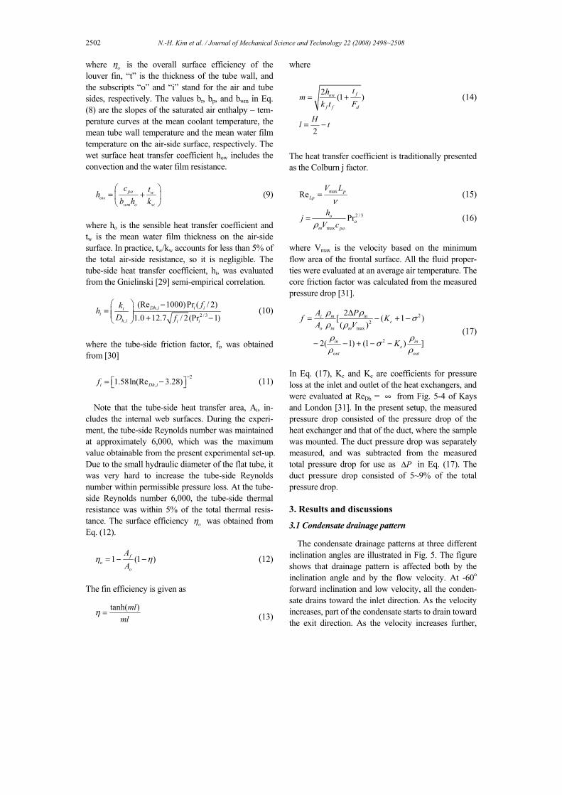
In Fig. 7, the same data are replotted to show the effect of fin pitch at three different inclination angles. In Fig. 7, only backward inclination data are shown because not much difference exists between back-ward and forward inclination data. Fig. 7 shows that j factors are approximately the same independent of the fin pitch, although a slight increase at 2.0 mm fin pitch is noticed. The friction factors are approxi-mately the same for 1.5 mm and 2.0 mm fin pitch, while they significantly increase at 1.25 mm fin pitch. Significant fin bridging of the condensate at 1.25 mm fin pitch appears to have caused large f factors.
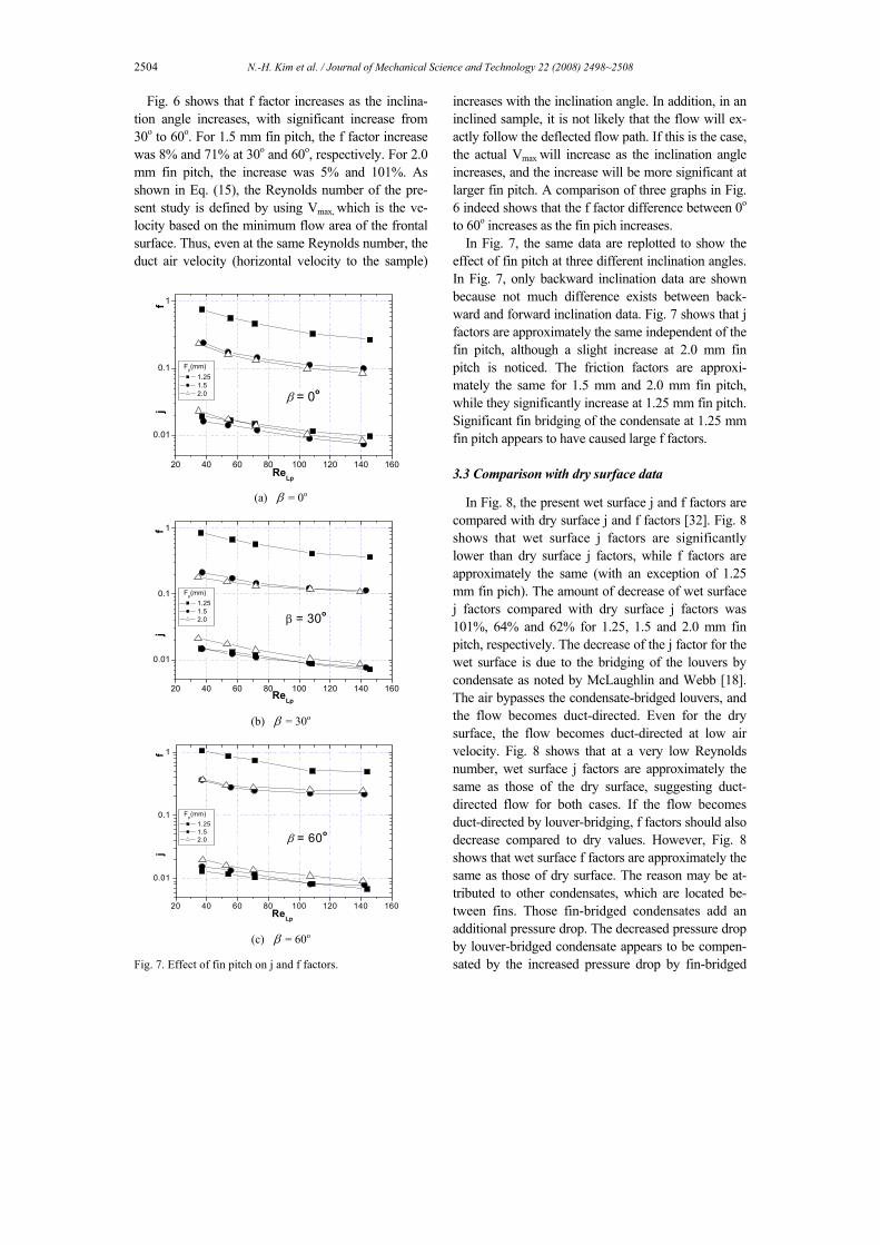
3.3 Comparison with dry surface data
In Fig. 8, the present wet surface j and f factors are compared with dry surface j and f factors [32]. Fig. 8 shows that wet surface j factors are significantly lower than dry surface j factors, while f factors are approximately the same (with an exception of 1.25 mm fin pich). The amount of decrease of wet surface j factors compared with dry surface j factors was 101%, 64% and 62% for 1.25, 1.5 and 2.0 mm fin pitch, respectively. The decrease of the j factor for the wet surface is due to the bridging of the louvers by condensate as noted by McLaughlin and Webb [18]. The air bypasses the condensate-bridged louvers, and the flow becomes duct-directed. Even for the dry surface, the flow becomes duct-directed at low air velocity. Fig. 8 shows that at a very low Reynolds number, wet surface j factors are approximately the same as those of the dry surface, suggesting duct-directed flow for both cases. If the flow becomes duct-directed by louver-bridging, f factors should also decrease compared to dry values. However, Fig. 8 shows that wet surface f factors are approximately the same as those of dry surface. The reason may be at-tributed to other condensates, which are located be-tween fins. Those fin-bridged condensates add an additional pressure drop. The decreased pressure drop by louver-bridged condensate appears to be compen-sated by the increased pressure drop by fin-bridged
N.-H. Kim et al. / Journal of Mechanical Science and Technology 22 (2008) 2498~2508 2505
20 40 60 80 100 120 140 160
0.01
0.1
1
Fp = 1.25 mm
ReLp
j
f
0o dry 0o wet
30o dry 30o wet
60o dry 60o wet
(a) Fp = 1.25 mm
20 40 60 80 100 120 140 160
0.01
0.1
1
Fp = 1.5 mm
ReLp
j
f
0o dry 0o wet
30o dry 30o wet
60o dry 60o wet
(b) Fp = 1.5 mm
20 40 60 80 100 120 140 160
0.01
0.1
1
Fp = 2.0 mm
ReLp
j
f
0o dry 0o wet
30o dry 30o wet
60o dry 60o wet
(c) Fp = 2.0 mm
Fig. 8. Comparison of wet and dry j and f factors.
condensate. At 1.25 mm fin pitch, the wet surface f factors are 68% higher than dry surface values. Ex-cessive fin bridging at the small fin pitch appears to have caused a significant pressure drop for the wet surface.
3.4 Comparison with existing correlation
The literature reveals only one wet surface j and f factor correlation for louvered surfaces. Kim and Bullard [24] developed wet surface j and f correla-tions based on their own data, which cover flow depth
20 40 60 80 100 120 1400.0
0.5
1.0
1.5
2.0
j/jpr
ed
f/f p
red
ReLp
j/jpred f/fpred
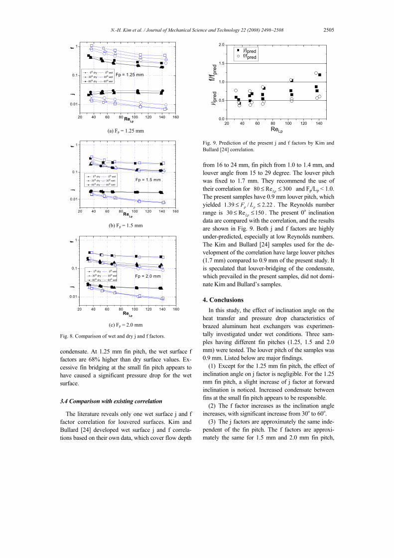
Fig. 9. Prediction of the present j and f factors by Kim and Bullard [24] correlation. from 16 to 24 mm, fin pitch from 1.0 to 1.4 mm, and louver angle from 15 to 29 degree. The louver pitch was fixed to 1.7 mm. They recommend the use of their correlation for 80 Re 300Lp≤ ≤ and Fp/Lp < 1.0. The present samples have 0.9 mm louver pitch, which yielded 1.39 / 2.22p pF L≤ ≤ . The Reynolds number range is 30 Re 150Lp≤ ≤ . The present 0o inclination data are compared with the correlation, and the results are shown in Fig. 9. Both j and f factors are highly under-predicted, especially at low Reynolds numbers. The Kim and Bullard [24] samples used for the de-velopment of the correlation have large louver pitches (1.7 mm) compared to 0.9 mm of the present study. It is speculated that louver-bridging of the condensate, which prevailed in the present samples, did not domi-nate Kim and Bullard’s samples.
4. Conclusions
In this study, the effect of inclination angle on the heat transfer and pressure drop characteristics of brazed aluminum heat exchangers was experimen-tally investigated under wet conditions. Three sam-ples having different fin pitches (1.25, 1.5 and 2.0 mm) were tested. The louver pitch of the samples was 0.9 mm. Listed below are major findings.
(1) Except for the 1.25 mm fin pitch, the effect of inclination angle on j factor is negligible. For the 1.25 mm fin pitch, a slight increase of j factor at forward inclination is noticed. Increased condensate between fins at the small fin pitch appears to be responsible.
(2) The f factor increases as the inclination angle increases, with significant increase from 30o to 60o.
(3) The j factors are approximately the same inde-pendent of the fin pitch. The f factors are approxi-mately the same for 1.5 mm and 2.0 mm fin pitch,
2506 N.-H. Kim et al. / Journal of Mechanical Science and Technology 22 (2008) 2498~2508
while they significantly increase at 1.25 mm fin pitch. Significant fin bridging of the condensate at 1.25 mm fin pitch appears to have caused large f factors.
(4) Wet surface j factors are significantly lower than dry surface j factors, while f factors are approxi-mately the same. The decrease of the j factor for the wet surface appears to be due to the bridging of the louvers by condensate. For the f factor, the decreased pressure drop by louver-bridged condensate appears to be compensated by the increased pressure drop by fin-bridged condensate.
(5) Kim and Bullard [24] correlation significantly overpredicts the present j and f factors. The difference of the louver pich of the present sample and that of Kim and Bullard appears to be responsible.
Nomenclature-----------------------------------------------------------
A : Heat transfer area (m2) Afr : Frontal area of the heat exchanger (m2) Amin : Minimum flow are at the core of the heat ex-
changer (m2)
br12 : Slope of the air saturation curve between the inlet and exit air temperature (J/kg·K)
bp : Slope of the air saturation curve between the outside and inside tube wall temperature (J/kg·K)
br : Slope of the air saturation curve between the mean tube and water temperature (J/kg·K)
bwm : Slope of the air saturation curve at the mean water film temperature of the airside surface (J/kg·K)
cp : Specific heat (J/kg·s) Cr : Heat capacity ratio (dimensionless) [Eq. (6)] Dh : Hydraulic diameter (m) FD : Depth of fin array in flow direction (m) Fp : Fin pitch (m)
f : Airside friction factor (dimensionless) [Eq. (17)]
fi : Tube-side friction factor (dimensionless) [Eq. (11)]
H : Fin height (m) h : Heat transfer coefficient (W/m2·K) i : Enthalpy (J/kg) j : Colburn j factor (dimensionless) [Eq. (16)] k : Thermal conductivity (W/m·K) Ll : Louver length (m) Lp : Louver pitch (m) m : Mass flow rate (kg/s) NTU : Number of transfer units (dimensionless)
[Eq. (7)]
Pr : Prandtl number (dimensionless) (= pckµ
)
Q : Heat transfer rate (W) ReLp : Reynolds number based on Lp (dimensionless)
(= max pV Lν
)
ReDh : Tube-side Reynolds number based on Dh,
(dimensionless) (= hVDν
)
S1 : Non-louvered inlet and exit fin length (m) S2 : Re-direction louver length (m) t : Tube wall thickness, film thickness (m) T : Temperature (K) Tp : Tube pitch (m) tf : Fin thickness (m) U : Overall heat transfer coefficient (W/m2·K) V : Velocity in the tube (m/s) Vmax : Velocity based on the minimum flow area of
the frontal surface (m/s) Greek letters
α : Louver angle (deg) β : Inclination angle (deg) ε : Thermal effectiveness (dimensionless) [Eq.
(4)] P∆ : Pressure loss (Pa)
η : Fin efficiency (dimensionless) [Eq. (13)] oη : Surface efficiency (dimensionless) [Eq. (12)]
ρ : Density (kg/m3) µ : Dynamic viscosity (kg/m·s) ν : Kinematic viscosity (m2/s) σ : Contraction ratio of the cross-sectional area
(dimensionless) (=Amin/Afr) Subscripts
a : Air c : Heat exchanger core i : Tube-side in : Inlet f : Fin m : Mean max : Maximum min : Minimum o : Outside out : Outlet t : Tube w : Water, wet surface
N.-H. Kim et al. / Journal of Mechanical Science and Technology 22 (2008) 2498~2508 2507
References
[1] R. L. Webb and S.-H. Jung, Air-side performance of enhanced brazed aluminum heat exchangers, ASHRAE Trans., 98(2) (1992) 391-410.
[2] R. L. Webb and H. Lee, Brazed aluminum heat exchangers for residential air-conditioning, J. En-hanced Heat Transfer, 8 (2001) 1-14.
[3] C. J. Davenport, Heat transfer and fluid flow in louvered triangular ducts, PhD Thesis, Lanchester Polytechnic, U. K. (1980).
[4] A. Achaichia and T. A. Cowell, Heat transfer and pressure drop characteristics of flat tube and lou-vered plate fin surfaces, Exp. Thermal Fluid Science, 1 (1988) 147-157.
[5] C. J. Davenport, Correlation of heat transfer and flow friction characteristics of louvered fin, AIChE Symp. Ser., 79 (1983) 19-27.
[6] B. Sunden and J. Svantessen, Correlation of j and f factors for multi-louvered heat transfer surfaces, Proceedings of Third UK National Heat Transfer Conference, (1992) 805-811.
[7] Y.-J. Chang and C.-C. Wang, Air-side performance of brazed aluminum heat exchangers, J. Enhanced Heat Transfer, 3 (1) (1996) 15-28.
[8] M.-H. Kim and W.-Y. Park, Air-side heat transfer and pressure drop characteristics of louvered fin heat exchangers, Proceedings of the KSME '98 fall conference, (1998) 23-128.
[9] N.-H. Kim and J.-P. Cho, Airside performance of louver-finned flat aluminum heat exchangers at a low velocity region, printing in Heat and Mass Transfer, (2008).
[10] A. Achaichia and T. A. Cowell, A finite difference analysis of fully developed periodic laminar flow in inclined louvered arrays, Proceedings of Second UK National Heat Transfer Conference, Glasgow, (1988) 883-888.
[11] M. Hiramatsu, T. Ishimaru and K. Matsuzaki, Research on fins for air-conditioning heat exchang-ers (first report, numerical analysis of heat transfer on louvered fins), JSME International Journal, Se-ries II, 33 (4) (1990) Paper No. 88-1254A.
[12] K. Suga, H. Aoki and T. Shingawa, Numerical analysis on two dimensional flow and heat transfer on louvered fins using overlaid grids, JSME Inter-national Journal, 33 (1990) 122-127.
[13] C. S. Kang and T. M. Choi, A basic study on air flow characteristics in louvered fins, KSME J., 17 (5) (1993) 1276-1293.
[14] A. Achaichia, M. R. Heikal, Y. Sulaimna and T. A. Cowell, T. A., Numerical Investigation of flow and friction in louver fin arrays, Proceedings of the Tenth International Heat Transfer Conference, 4 (1994) 333-338.
[15] K. S. Lee, C. D. Jeon and J. H. Lee, Study of flow structure and pressure drop characteristics in lou-vered-fin type heat exchanger, J. SAREK, 6 (2), (1994) 140-154.
[16] D. K. Tafti, G. Wang and W. Lin, Flow transition in a multi-louvered fin array, Int. J. Heat Mass Transfer, 43 (2000) 901-919.
[17] W. J. McLaughlin and R. L. Webb, Condensate drainage and retention in louver fin automotive evaporators, SAE Technical Paper Series, (2000) 2000-01-0575.
[18] W. J. McLaughlin and R. L. Webb, Wet airside performance of louver fin automotive evaporators, SAE Technical Paper Series, (2000) 2000-01-0574.
[19] M.-H. Kim and C.-W. Bullard, Airside perform-ance of brazed aluminum heat exchanger under de-humidifying conditions, Int. J. Refrigeration, 25 (2002) 924-934.
[20] H. G. Groehn, Heat transfer and flow resistance of yawed tube bundle heat exchangers, Heat Ex-changer Theory and Practice, Hemisphere (1983) 299-310.
[21] M. Monheit and J. Freim, Effect of tube bank inclination on the thermal hydraulic performance of air cooled heat exchangers, Proceedings of 8th Int. Heat Transfer Conf., (1986) 2727-2732.
[22] W. R. Chang, C. C. Wang and Y. J. Chang, Effect of an inclination angle on the heat transfer and pres-sure drop characteristics of a wavy finned-tube heat exchanger, ASHRAE Trans., 100 (2) (1994) 826-832.
[23] H. Osada, H. Aoki, T. Ohara, T. and K. Kuroya-nagi, Experimental analysis for enhancing automo-tive evaporator fin performance, Proceedings of the International Conference on Compact Heat Ex-changers and Enhancement Technologies for the Process Industries, (1999) 439-445.
[24] M.-H. Kim, B. Youn and C. W. Bullard, Effect of inclination on the airside performance of a brazed aluminum heat exchanger under dry and wet condi-tions, Int. J. Heat Mass Transfer, 44 (2001) 4613-4623.
[25] M.-H. Kim, S. Song and C. W. Bullard, Effect of inlet humidity condition on the airside performance of an inclined brazed aluminum evaporator, Int. J.
2508 N.-H. Kim et al. / Journal of Mechanical Science and Technology 22 (2008) 2498~2508
Refrigeration, 25 (2002) 611-620. [26] ASHRAE Standard 41.1, Standard method for
temperature measurement, ASHRAE (1986). [27] ASHRAE Standard 41.2, Standard method for
laboratory air-flow measurement, ASHRAE (1987). [28] ASHRAE Standard 41.5, Standard measurement
guide, engineering analysis of experimental data, ASHRAE (1975).
[29] V. Gnielinski, New equations for heat and mass transfer in turbulent pipe flows, Int. Chem. Eng., 16 (1976) 359-368.
[30] G. K. Filonenko, Hydraulic resistance in pipes, Teploenergetica, 1 (1954) 40-44.
[31] W. M. Kays and A. L. London, Compact heat exchangers, McGraw Hill Pub. (1984).
[32] D.-Y. Kim, J.-P. Cho, N.-H. Kim, N.-H. Park and
J.-H. Hwang, Airside performance of aluminum heat exchangers at different inclination angles, J. SAREK, 20 (3) (2008) 182-189.
Nae-Hyun Kim is a Professor of Mechanical Engineering, Univer-sity of Incheon. His area of interest spans boiling and condensation, heat transfer enhancement and heat exchanger design. He has been active in heat transfer community, and was a Chairman of Thermal
Engineering Division of KSME. He holds several edito-rial position including Journal of Enhanced Heat Trans-fer. He is a recipient of Asian Academic Award awarded by SAREK and JSRAE.