Embed Size (px)
Citation preview

WET-CHEMICAL SUPPORT REMOVAL FOR ADDITIVE MANUFACTURED METAL PARTS
T. Schmithüsen* and Prof. Dr.-Ing. Johannes Henrich Schleifenbaum*†
*Fraunhofer Institute for Laser Technology ILT, Germany, 52074 Aachen†RWTH Aachen University, Chair for Digital Additive Production DAP, Germany, 52074 Aachen
Abstract The additive manufacturing technology laser powder bed fusion (LPBF) offers great flexibility regarding
the manufacturing of complex component structures. Due to the process, support structures have to be manufactured for overhanging component surfaces in order to guarantee dimensional accuracy and reduce distortion. However, these must be removed after manufacturing. Especially for internally supported component surfaces, removal is only possible by means of tool-free technologies. A promising approach for a tool-free support removal is the wet-chemical ablation, in which the support structures are removed by chemical dissolution. So far, the approach has been tested for a few materials (e.g. stainless steel). In order to extend the use of this automatable approach to further AM materials, the influence of different etching agents on different additive aluminium alloys with regard to material ablation and surface influence will be investigated. Finally, the applicability of the results to a supported component will be tested.
Introduction The additive manufacturing process Laser Powder Bed Fusion offers many advantages over
conventional manufacturing processes. For example, almost any complex component can be produced, such as topologically optimized lightweight components (see Figure 1), which would be inconceivable with conventional manufacturing processes.
Figure 1: Topology optimized stub axle with integrated lattice structures [SCH-17]
A major challenge posed by the LPBF process, however, is in most cases the need to use and remove support structures on critically inclined component surfaces (α < 45 ° regarding substrate plate). These are mainly used for dimensionally accurate mapping of component contours and to reduce distortion by absorbing process-related internal stresses. Furthermore, they serve to transfer the process heat to the substrate plate and are therefore indispensable for the LPBF process [BUC-2013]. A major challenge for the economical use of the LPBF process in industrial series production is currently still the high manual effort involved in removing support structures. According to the state of the art (SoA), the components are usually treated by simple hand tools (e.g. pliers, chisels) or by machining (e.g. milling, turning). Lefky [LEF-18] and Schmithüsen [SCH-18] investigated the first approaches that could be automated. They investigated the removal of supporting structures by means of wet-chemical post-processing. In this approach, the component is completely or partially immersed in a reactive medium (e.g. acid or lye), which also removes material from the component and the supporting structures and
2051
Solid Freeform Fabrication 2019: Proceedings of the 30th Annual InternationalSolid Freeform Fabrication Symposium – An Additive Manufacturing Conference
Reviewed Paper

separates them from the component. Compared to the state of the art, this process approach has some potential. On the one hand, the components can be processed by bulk material treatment independent of volume and number. In applications where no milled functional surfaces are required, the components do not have to be measured and referenced beforehand, thus eliminating the need for machining steps. The tool-free treatment also supports internal supported surfaces (e.g. cooling channels) and undercuts. So far, the process approach has only been tested on a few materials that can be processed additively (hereinafter referred to as AM material, stainless steel [LEF-18], AlSi10Mg [SCH-19]). In order to transfer the applicability to other AM materials, the influence of an alkaline (NaOH) and an acidic (H3PO4) etching agent on different aluminium alloys (AlSi10Mg, AlSi12, AlSi9Cu3) with regard to material removal and surface influence will first be investigated in this study. In order to determine treatment times in line with actual practice, webs manufactured from individual melt traces, which are similar to vector supports in terms of their dimensions, are etched in a preliminary test and the time until complete dissolution is determined. Based on the results of these investigations, potential etching agent-material combinations are determined which contribute to a high and uniform material removal with simultaneous non-damage of the component surface (e.g. scouring or fissuring of the surface, change of the chemical composition of the near-surface boundary layer). Finally, a supported volume body (twin cantilever) is used to check its applicability to supported components. The test geometries are manufactured from the three aluminium alloys and supported with the potentially suitable etching agents identified in the preliminary tests. The test is successful if the support structures can be resolved according to the investigations by Schmithuesen (cf. [SCH-19], Chapter 5).
Experimental planning
Materials and etching agents
Within the scope of the study, a total of three additive processable materials (hereinafter AM materials) and two different etching agents are investigated. The following table shows the materials with the essential parameters.
Table 1: Specifications of the investigated materials
The etching agents shown in Table 2 are used for the material removal tests.
Material
Particle size distribution *
D10, D90 [μm]
Chemical composition**
Al [%]
Si [%]
Fe[%]
Mg[%]
Cu [%]
Ni[%]
Zn[%]
Ti[%]
AlSi10Mg20 – 63 rest
9.0-11.0 0.5 0.2-0.5 0.05 0.3 0.1 0.15AlSi9Cu3 8.0-11.0 0.8 0.1-0.5 2.0-3.5 - 1.2 0.15
AlSi12 10.5-13.5 0.5 0.05 0.05 - 0.1 0.15* according to manufacturer specifications** according to material data sheet
2052

Table 2: Specifications of the investigated etching agents [MIC-19], [VWR-19]
Test geometries
The bars shown in Figure 2 are used to determine the duration of treatment. The cube geometries shown in Figure 2 (a) are used to investigate the influence of the various etching agents on the various aluminium materials in terms of material removal and surface influence. The cubes are manufactured on a SLM Solutions 280 HL of the manufacturer SLM Solutions Group AG with the material and machine-specific LPBF process parameters (laser power PL = 350 W, scanning speed vs = 1650 mm/s, hatch distance Δys = 130 μm, layer thickness Ds = 30 μm). After the LPBF manufacturing, the samples are separated from the substrate plate using a band saw and milled to a defined dimension using machining to compare the results. The side surfaces remain untreated to determine the surface roughness before and after the etching treatment.
Figure 2: Schematic drawing of the investigated test samples: (a) Walls, (b) Cubes, (c) Twin cantilever
The twin cantilevers shown in Figure 2 (c) are used to check the applicability of the results to supported components. According to the investigations of Schmithüsen [SCH-19] the Twincantilever has SoA vector supports (SoA – state of the art) for the imaging of the component edges as well as SoA volume supports or porous volume supports to ensure manufacturability (cf. [SCH-19], chapter 2.1 and chapter 5). Thus, the use of porous volume supports as a replacement for SoA volume supports can also be examined within the scope of this test for the feasibility of complete support removal. The transferability test is successful if the SoA vector supports and the porous volume supports can be completely dissolved and SoA volume supports remain present at the same time.
Experiment setup and procedure
Etching treatment
For the etching treatment, the respective samples (bars, cubes, twin cantilever) are clamped into an etching-resistant spring clamp and immersed into the etching agent according to the Figure 3 the cubes, rubber plates resistant to etching agents are additionally clamped between the jaws of the spring clamp and the sample.
Etching agent pH-value Chemical composition*
Temperature[°C]
Volume [mL]Walls Cubes** Twincantilever
Sodiumhydroxide alkaline 50.0% NaOH(50%) +50.0% H2O
50 25 100 200Technietch Al80 acidic
73.0% H3PO4 +3.1% HNO3 +
3.3% CH3COOH +20.6% H2O
* according to material data sheet** amount for 3 cubes
10 mm
20 mm
5 mm
Bui
ld-u
p di
rect
ion
(b)
10 mm10 mm
10 mm
as built10mm
machined
Measured surface Sa
Single scan
(a) (c)
20 mm
10 mm
2053
..........
ii I
The rubber plates are intended to prevent material removal from the milled surfaces and thus ensure simple referencing of the scanned untreated or treated 3D sample geometries. For each test, three cubes are immersed simultaneously in the etching agent for statistical purposes. To finish the etching treatment, the cubes are neutralized under running water. Unused etching agent is used for each test. The following Figure 3 illustrates the experimental setup and sequence for the investigation of the fundamental cause-effect relationships.
Figure 3: Experimental setup and procedure for the investigations
For the tests to determine the applicability to supported components, a similar procedure is chosen as for the basic investigations with the cubes. In contrast, according to Table 2 only the quantity of etching agent changes.
Determination of treatment duration
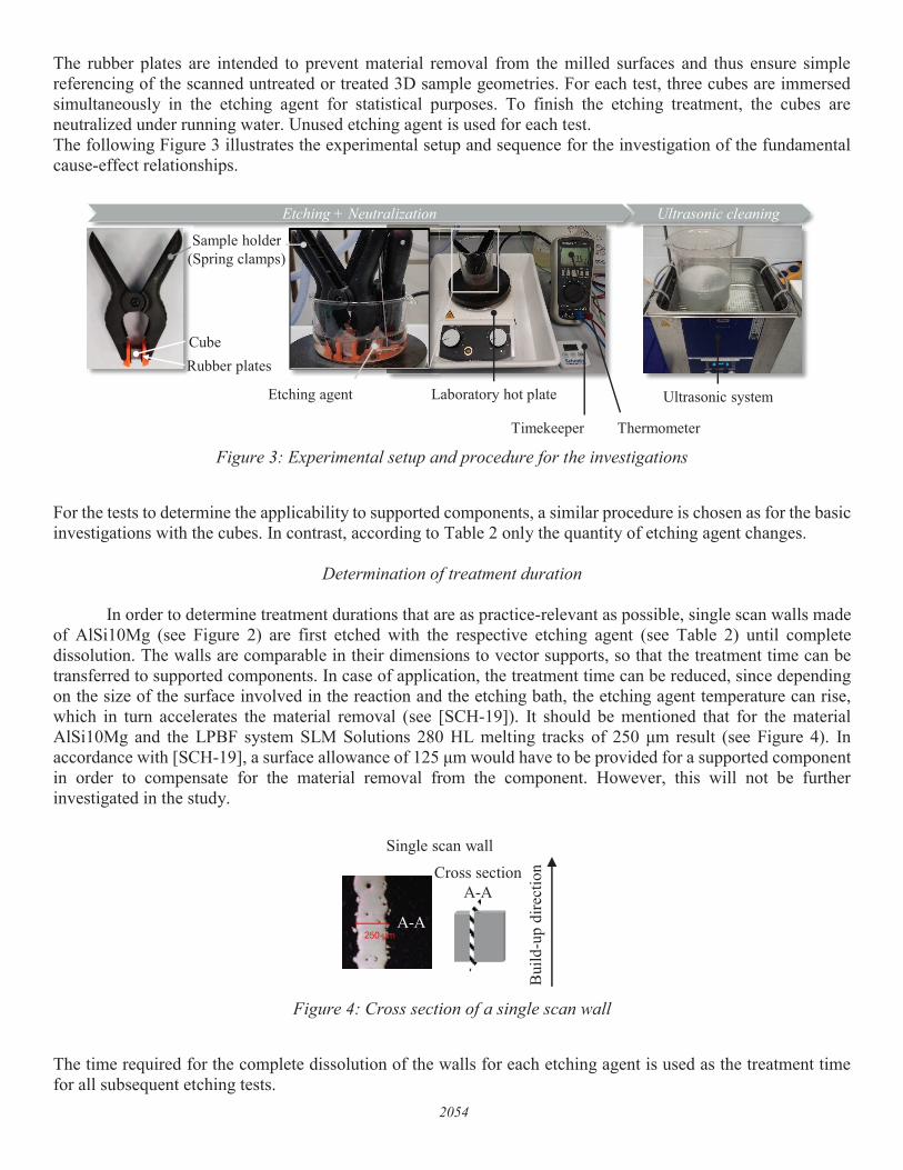
In order to determine treatment durations that are as practice-relevant as possible, single scan walls made of AlSi10Mg (see Figure 2) are first etched with the respective etching agent (see Table 2) until complete dissolution. The walls are comparable in their dimensions to vector supports, so that the treatment time can be transferred to supported components. In case of application, the treatment time can be reduced, since depending on the size of the surface involved in the reaction and the etching bath, the etching agent temperature can rise, which in turn accelerates the material removal (see [SCH-19]). It should be mentioned that for the material AlSi10Mg and the LPBF system SLM Solutions 280 HL melting tracks of 250 μm result (see Figure 4). In accordance with [SCH-19], a surface allowance of 125 μm would have to be provided for a supported component in order to compensate for the material removal from the component. However, this will not be further investigated in the study.
Figure 4: Cross section of a single scan wall
The time required for the complete dissolution of the walls for each etching agent is used as the treatment time for all subsequent etching tests.
Sample holder (Spring clamps)
Etching agent Laboratory hot plate Ultrasonic system
er
Etching + Neutralization Ultrasonic cleaning
Timekeeper Thermometer
CubeRubber plates
Bui
ld-u
p di
rect
ion
Single scan wallCross section
A-A
A-A
2054
I •

Determination of material removal
Within the scope of the study, both the mass related material removal (in the following mass ablation or mass reduction) and the length related material removal (in the following depth ablation or depth reduction) are determined. To determine the material removal (mass and depth removal), the cubes are weighed and measured by 3D scan (strip light projection Atos 3D GOM 5M) before etching and after ultrasonic treatment. From the differences, the percentage decrease in mass is determined for the defined treatment times (cf. chapter "Materials and etching agents"). The depth reduction or depth ablation (mm) can be determined using the evaluation software of the 3D scanner. For this purpose, the orthogonal deviation between the treated and untreated 3D sample geometry is determined. By averaging measurement points randomly distributed over the cube surface, the mean value of the depth ablation and the standard deviation can be approximately determined. For statistical purposes, three cubes are measured for each material and the results averaged. Figure 5 shows an example of a cube measured by means of a 3D scan.
Figure 5: Exemplary presentation of the 3D scanned cubes (AlSi12, build-up direction: z)
Determination of the surface influence
The surface influence is determined both macroscopically and microscopically. By measuring the surface
roughness before and after the treatment, a statement can be made about the influence of the etching treatment on the surface quality. With the help of SEM images, the effect of the treatment can be qualitatively observed on a microscopic level. An EDX analysis of the near-surface boundary layer provides information on the potential change in the chemical composition of the near-surface microstructure. The measurements are made on cube surfaces perpendicular to the substrate plate.
2055
( mm]
0.03
0.01
0 .00
- 0 .01
- 0 .03
- 0.04
- 0.06
- 0 .07
- 0 .09
- 0.10

Experiment results
Duration of treatment
While the walls in the alkaline etching agent dissolve completely after just a few minutes (t = 15 min), no material removal can be visually detected with the acidic etching agent even after t = 2:30 hrs. Also the increase of the etching agent temperature to T = 80 °C and extension of the treatment time to t = 6 hrs does not lead to a significant material removal (see Figure 6).
Figure 6: Exemplary presentation of the single scan etching investigation by means of the alkaline etching
agent
The potential cause for the reduced material removal contrary to the manufacturer's specifications (cf. [MIC-19]) may be the aluminium oxide layer on the surface of the samples, as this must first be dissolved in order to allow a significant material removal. This hypothesis is confirmed by a comparative etching test between an untreated (with oxide layer) and a roughened (without oxide layer) sample. As can be seen in Figure 7 the roughened sample shows a stronger gas development compared to the untreated sample. This is an indication of a stronger chemical reaction between the aluminium alloy and the etching agent and thus an increased material removal.
Figure 7: Exemplary presentation of the etching test with an as built wall (left) and sanded wall (right)
Since a previous roughening of the supported components in particular of the supporting structures is not possible or only possible to a limited extent in case of application, wet-chemical removal by means of acidic etching agent is considered impracticable and will not be pursued further in the study. All subsequent etching tests are performed with the acidic etching agent. The treatment duration is set to t = 15 min.
as built during treatment after treatment
10 mm
Single scan wall
as built wall (with oxide layer)
sanded wall (removed/ reduced oxide layer)
significant noticeable gas evolution at surface
10 mm
2056

Visual inspection
In Table 3 the untreated, etched and ultrasonically cleaned cubes are visualized.
Table 3: Exemplary presentation of the investigated cubes
According to the investigations of Schmithüsen [SCH-18], the cubes of all three materials show a dark discoloration immediately after the etching process. The hypothesis is made that the dark layer of all materials is a remaining silicon layer. Furthermore, the cubes have a visually smoother surface after treatment than in the untreated state.
Material ablation
In order to quantify the material ablation, the cubes are weighed and measured using a 3D scan before and after each treatment (see chapter "Determination of material removal"). The following diagrams in Figure 8 show the percentage mass ablation (mass reduction) and depth ablation (depth reduction) averaged over three measurements for the treatment duration t = 15 min.
Figure 8: Percentage mass reduction and depth reduction after t = 15 min treatment
Material AlSi10Mg AlSi9Cu3 AlSi12
as built
etched
ultrasonically cleaned
5mm
AlSi10Mg AlSi9Cu3 AlSi121,000
1,125
1,250
1,375
1,500
1,625
1,750
1,875
2,000
Mas
s re
duct
ion
[%]
AlSi10Mg AlSi9Cu3 AlSi120,00
-0,01
-0,02
-0,03
-0,04
-0,05
-0,06
-0,07
Dep
th re
duct
ion
[mm
]
2057

As can be seen in Figure 8 mass and depth reduction is similar in comparison of the materials. The material removal tends to be highest for cubes made of AlSi10Mg and lowest for cubes made of AlSi9Cu3. This can be caused by the different chemical compositions or the different initial roughnesses (or roughness in the untreated state). According to the investigations of Schmithüsen [SCH-18], greater material removal occurs due to the levelling of roughness peaks with larger initial roughnesses.
Surface condition
The following Figure 9 shows the measured surface roughnesses of the three aluminium alloys before and after wet chemical treatment. For statistical verification, three samples per material are measured and the result averaged.
Figure 9: Averaged values of surface roughness before (as built) and after (etched + ultrasonically cleaned)
treatment
It can be seen that the treatment with the alkaline etching agent reduces the surface roughness of the cubes made of aluminium alloys AlSi10Mg and AlSi12. The surface roughness of the cube made of AlSi9Cu3, on the other hand, has increased slightly. However, since the increase is in the range of the standard deviation, this effect can also be caused by statistical outliers. As mentioned in the previous chapter, the removal of material from the AlSi10Mg cubes is greatest in relation to the other materials. Since the cubes made of AlSi10Mg also have the highest initial roughness, the hypothesis can be confirmed that the increased material removal of AlSi10Mg is mainly due to the higher initial roughness.
Chemical composition of the near-surface layer
Due to the chemical treatment of the samples, a brownish layer is formed on the surface. In order to determine the composition of this layer and to investigate how the effect of the etching agent influences the chemical composition of the near-surface layer, the samples are examined under a scanning electron microscope (SEM) and an EDX analysis is also performed. The following pictures in Figure 10 show the respective surfaces before and after etching or after ultrasonic cleaning.
as built treated as built treated as built treatedAlSi10Mg AlSi9Cu3 AlSi12
0
2
4
6
8
10
12
14
Surf
ace
roug
hnes
s [μm
]
2058

Figure 10: SEM images of as built, etched and ultrasonically cleaned sample surfaces
It can be seen that the etched surface has a lamellar layer (perpendicular to the surface) compared to the untreated surface. However, this layer is no longer visible after ultrasonic cleaning. This process is also reflected in the EDX analysis. The Figure 11 shows the percentage chemical compositions of the three different treatment states of the respective etching agent-material combination. The focus of the investigations in this study is on the respective main elements of the materials: aluminium (Al), silicon (Si), magnesium (Mg) and copper (Cu).
Material AlSi10Mg AlSi9Cu3 AlSi12
as built
etched
ultrasonically cleaned
500x
5000x
100 μm
10 μm
Bui
ld-u
p di
rect
ion
2059

Figure 11: Element fractions of the as built and treated (etched and ultrasonically cleaned) samples after EDX
analysis
Since the proportion of aluminium in the etched surface is reduced and the proportion of silicon (relative to the untreated surface) increased, it can be assumed that the sodium hydroxide reacts predominantly with aluminium and that a lamellar brittle silicon layer remains on the component surface. In addition, ultrasonic cleaning most probably removes the brittle silicon layer almost completely, since the chemical composition of the ultrasonically cleaned surface comes close to that of the untreated surface. Thus, the hypothesis previously made (see chapter "Visual inspection") that a silicon layer remains during the etching process of all three aluminium alloys, which is almost completely removed after ultrasonic cleaning, can be confirmed.
Application testing
From the results on the fundamental interactions between the different etching agents and the respective aluminium alloys, the sodium hydroxide solution can be classified as potentially suitable for all three aluminium alloys. In order to test the applicability of this combination on real-life supported components, supported twin cantilevers made of the three materials are treated. The transferability of the results is considered successful if the support structures can be completely removed according to the investigations of Schmithüsen [SCH-19]. The following Figure 12 shows the twin cantilevers before and after the treatment.
as built etched ultrasonic
0
10
20
30
40
50
60
70
80
90
100
as built etched ultrasonic as built etched ultrasonic
Elem
ent f
ract
ions
[% b
y w
eigh
t]
AlSi10Mg
AlSiMg
AlSi9Cu3
AlSiCu
AlSi12
AlSi
2060
- /. ~ ~
I
\ ~ / ............ ~ --•-
. ·•·. \ J --•-\ I . ·•·. "' / ~
" / \ ,1, I \/ \/ /\ I'- , '
, , '
, . .\ ~/. .. ' , '.
, ' , ' , ' , ' ' , ,
' ' , , '
, \ , ' '
, ' ' , , '
' ,, ...

Figure 12: Exemplary presentation of the as built, etched and ultrasonically cleaned Twincantilever (1 = SoA-
vector supports + SoA-volume supports; 2 = SoA-vector supports + porous supports)
After visual evaluation, the SoA-support structures and porous support structures of all three materials dissolve completely according to the investigations of Schmithüsen [SCH-19]. A direct comparison of the materials shows that the twin cantilever made of the aluminium alloy AlSi9Cu3 is already more dissolved than that of the other two aluminium alloys. This can be seen in particular in the remaining SoA-volume supports. Whether this effect is caused by the different chemical composition of the alloys or different material densities as a result of the LPBF process cannot be determined within the scope of the study. The etching times for the complete dissolution of the SoA-vector supports and the porous volume supports also differ. With AlSi10Mg the SoA-vector supports and porous volume supports are completely dissolved after 28:30 min, with AlSi0Cu3 after 24:30 min and with AlSi12 already after 21:30 min. The reason for this is probably the delayed increase of the etching agent temperature during the reaction with AlSi10Mg compared to AlSi9Cu3 or AlSi12 (see Figure 13).
Material AlSi10Mg AlSi9Cu3 AlSi12
as built
etched
ultrasonicallycleaned
as built vs. treated
10 μm
Bui
ld-u
p di
rect
ion
1 2
28:30 min 24:30 min 21:30 min
2061

Figure 13: Recorded etching agent temperature profiles from the twin cantilever support removal tests
The cause for the different degrees of heating of the etching agent depending on the respective aluminium alloy cannot be determined within the scope of the study.
Conclusion and Outlook
Within the scope of the present study, the fundamental influence of alkaline and acidic etching agent on various aluminium alloys with regard to material removal and surface influence is determined. From the preliminary tests to determine the etching times it emerges that the acidic etching agent is not suitable for wet-chemical support removal, as it does not cause any measurable material removal from the samples in comparison to the alkaline etching agent. However, the alkaline etching agent is suitable for all aluminium alloys investigated in order to cause material removal. While the treatment with the alkaline etching agent reduces the surface roughness of the aluminium alloys AlSi10Mg and AlSi12, the surface roughness of the AlSi9Cu3 samples has slightly increased. However, the increase is in the range of the standard deviation, so that this effect can also be caused by statistical outliers. Also the applicability on a real supported demonstrator component can be confirmed. Similar to the investigations of Schmithüsen [SCH-19], the SoA-vector supports and porous volume supports dissolve faster than the SoA-volume supports. The investigations carried out within the scope of this study can thus advance the expansion of this process approach to other AM materials. Further investigations will examine the influence of potential heat treatments and different layer thicknesses on material removal and surface influence. Furthermore, the influence of the ratio of etching agent quantity and component volume on the resulting etching agent temperature and thus on the processing time and etching agent consumption will be investigated. In addition, the process approach is to be transferred to other materials by adapting the etching agents.
0 5 10 15 20 25 3040
50
60
70
80
90
100
etch
ing
agen
t tem
pera
ture
[°C
]
etching time [min]
AlSi10Mg AlSi9Cu3 AlSi12
2062

Literature [BUC-13] Buchbinder D.: Selective Laser Melting of Aluminium Alloys, Dissertation, Aachen, 2013 [LEF-18] Lefky, C.: Corrosion and Sensitized Microstructure Evolution of 3D Printed Stainless Steel 316
and Inconel 718 Dissolvable Supports, Dissertation, Tempe, 2018 [MIC-19] Micro-chemicals: Data sheet Technietch 80, www.microchemicals.de, access on 6 June 2019 [SCH-19] Schmithüsen, T., Schleifenbaum, J.H., Laag, T.:
Microscopic support design for the wet-chemical post processing of LPBF manufactured parts made of AlSi10Mg, Rapidtech 2019
[SCH-18] Schmithüsen, T., Bremen, S., Schleifenbaum, J.H.:
Automatable Support Removal and Surface Smoothing of Additive Manufactured Parts Made of AlSi10Mg, DDMC 2018
[SCH-17] Schmithüsen, T.: Topolight, Topology-optimized lightweight structures for sustainable resource efficiency in the automotive sector, Funding Code: BMBF 033RK020D, Final Report
[VWR-19] VWR International: Data sheet Sodium hydroxide 50% in aqueous solution,
https://uk.vwr.com/store/product/709421/sodium-hydroxide-50-in-aqueous-solution-technical, acces on 6 june 2019
2063