Embed Size (px)
Citation preview

HOT WATER/OIL
APPLICATION GUIDE
Publication No. CG-10-HWOPrinted in the U.S.A. 1105
www.slantfin.com
Guidelines for the design, purchase and installation of Slant/Fin Caravan oil-fired and dual fuel hot water modular boiler systems.
®
CONTENTSIntroduction . . . . . . . . . . . . . . . . . . . . . . . . . . . . . . . . . . . . . . .2Ratings and dimensions . . . . . . . . . . . . . . . . . . . . . . . . . . . .2-6Recommended piping and water flow . . . . . . . . . . . . . . . . .4-7Optional factory supply and return headers . . . . . . . . . . . . . .8Boiler room design . . . . . . . . . . . . . . . . . . . . . . . . . . . . . . . . .9Boiler room air supply requirements . . . . . . . . . . . . . . . . . . . .9Typical layouts for oil-fired systems . . . . . . . . . . . . . . . . . . .10Venting a oil-fired system . . . . . . . . . . . . . . . . . . . . . . . . .11,12Fuel oil storage facilities . . . . . . . . . . . . . . . . . . . . . . . . . . . .13Fuel oil delivery systems for single fuel burners . . . . . . .13-15Fuel oil delivery systems for dual fuel burners . . . . . . . .15-16
Controls . . . . . . . . . . . . . . . . . . . . . . . . . . . . . . . . . . . . . .17,18Field wiring at modules . . . . . . . . . . . . . . . . . . . . . . . . . . . . .19SC-3 system wiring . . . . . . . . . . . . . . . . . . . . . . . . . . . . . . . .20SC-3 ladder wiring . . . . . . . . . . . . . . . . . . . . . . . . . . . . . . . . .21SC-9 space heating wiring . . . . . . . . . . . . . . . . . . . . . . . . . .22SC-9 space heating ladder wiring . . . . . . . . . . . . . . . . . . . . .23SC-9 space and domestic hot water wiring . . . . . . . . . . . . .24SC-9 space and domestic hot water ladder wiring . . . . . . . .25Caravan warranty . . . . . . . . . . . . . . . . . . . . . . . . . . . . . . . . .26Request for Caravan rating plate . . . . . . . . . . . . . . . . . . .27,28
CODES AND STANDARDS
Oil-fired Caravan installations must comply to local codes or, in theabsence of local codes, to the ANSI/NFPA 31, Installation of OilBurning Equipment, latest edition.
In addition, where required by the authority having jurisdiction, theinstallation must conform to American Society of MechanicalEngineers Safety Codes for controls and safety devices for automatically fired boilers, No. CSD-1. The installation must alsoconform to the additional requirements of Slant/Fin Instruction Bookpublication no. L-40 latest edition.
All electrical wiring is to be done in accordance with the NationalElectrical Code ANSI/NFPA No. 70-latest edition and all local electrical codes. The unit must be electrically grounded if an exter-nal power source is used.
In Canada, the installation must be in accordance with standardsCGA B149.1 and B149.2, installation codes for oil burningappliances and equipment and/or local codes. All electricalconnections are to be made in accordance with Standard C.S.A.C22.1 Canadian Electrical Code Part 1 and/or local codes.
INTRODUCTION OF FRESH WATER
Introduction of excessive amounts of fresh water into a system cancause scaling and leave deposits in the boiler and the surroundingpipes. This will lead to inefficient boiler operation and breakdown.Fresh water will enter the system as a result of hidden leaks suchas may occur in underground piping. Relief valves should be pipedto a location that shows visible signs of relief.
Process applications that use fresh water, require the use of heatexchangers. Any process application that results in introduction offresh water into a boiler can cause scaling with deposits forming inthe boiler and surrounding piping. This will damage the boiler.Introduction of fresh water from leaks will cause similar damage.Use of fresh water will void warranty.
In some areas it may be necessary to use a feed water treatment tocontrol the corrosive makeup of the feed water. Check with the localauthority, to determine if the feed water will need a conditioningtreatment before being supplied to the boiler.
LOCAL CODE APPROVALS
New York City:New York City Bar No. 51-58
Pennsylvania:174-BT-S
WET-BASED CAST-IRON MODULAR BOILERS
2
Table 1: Oil Caravan ratings hot water models - LDWO Series (100 psi maximum working pressure)
INTRODUCTION
This Caravan application manual is intended to simplify the selec-tion and application of Slant/Fin modular systems for a variety ofspace heating and domestic hot water requirements. Where anyadditional information is required, contract your local wholesaler,Slant/Fin sales representative, or the Slant/Fin factory.
A. Design flexibility - Caravan modular boiler systems are available in virtually any size capacity simply by adding modules.
B. Boiler room design, size and flexibility - since Caravan modules have the burner and controls mounted to the front, they can be installed with minimum clearances as per codes, thus saving a significant amount of floor space.
C. Faster, easier installation - modules are completely factoryassembled, including individual jackets to save on-site labor.Optional easy to install supply and return headers with flexiblequick connect fittings are available for hot water systems.
D. Safety - each module contains an individual high limit controland a flame safeguard control. ASME relief valve is providedseparately for mounting directly on boiler.
E. Fast domestic hot water recovery - Caravan offers an externalheat exchanger of the positive circulating type.
LDWO-600-2-5 2 4.30 602 500 2900 435 14.9 31.0 1570 2"LDWO-750-2-6 2 5.20 728 596 3453 518 17.8 35.6 1790 2"LDWO-850-2-7 2 6.00 840 684 3967 595 20.4 45.2 2000 3"LDWO-900-3-5 3 6.40 896 750 4347 652 22.4 46.5 2355 3"LDWO-1100-3-6 3 7.80 1092 894 5180 777 26.7 53.4 2685 3"LDWO-1300-3-7 3 9.00 1260 1026 5947 892 30.6 67.8 3000 3"LDWO-1700-4-7 4 12.00 1680 1368 7933 1190 40.9 90.4 4000 3"LDWO-2100-5-7 5 15.00 2100 1710 9913 1487 51.1 113.0 5000 3"LDWO-2500-6-7 6 18.00 2520 2052 11893 1784 61.3 135.6 6000 3"LDWO-2900-7-7 7 21.00 2940 2394 13880 2082 71.5 158.2 7000 4"LDWO-3400-8-7 8 24.00 3360 2736 15860 2379 81.7 180.8 8000 4"
Model No.
No. ofHeatingModules
FiringRate
#2 OilGPH* Input
Ratings (MBH)
GrossOutput
‡ EDRWater
(Sq. Ft.)
I=B=RNet
Ratings(MBH)†
BoilerHorsepower
WaterContent
(gal.)ShipWt.
RecommendedHeader Size§
* Light oil, 140,000 Btuh per gallon.† Net ratings are based on a piping and pick-up allowance of 1.15. Slant/Fin should
be consulted before selecting a boiler for installation having unusual piping andpick-up requirements.
‡ Based on 150 Btuh per square foot E.D.R. at 170°F average water temperature.§ Modules in excess of 8 are piped in parallel to first eight.
For larger sizes, use multiples of the above.

3
LDWO-600-2-5 215⁄8 87⁄32 8 343⁄8 4'4"LDWO-750-2-6 25 929⁄32 8 373⁄4 4'4"LDWO-850-2-7 283⁄8 1119⁄32 9 411⁄8 4'4"LDWO-900-3-5 215⁄8 87⁄32 8 343⁄8 6'7"LDWO-1100-3-6 25 929⁄32 8 373⁄4 6'7"LDWO-1300-3-7 283⁄8 1119⁄32 9 411⁄8 6'7"LDWO-1700-4-7 283⁄8 1119⁄32 9 411⁄8 8'10"LDWO-2100-5-7 283⁄8 1119⁄32 9 411⁄8 11'1"LDWO-2500-6-7 283⁄8 1119⁄32 9 411⁄8 13'4"LDWO-2900-7-7 283⁄8 1119⁄32 9 411⁄8 15'7"LDWO-3400-8-7 283⁄8 1119⁄32 9 411⁄8 17'10"
Model No. ‡ A B C D † L *
* 27" spacing between modules.† Add 151⁄4" for dual fuel models.‡ Dual fuel prefix is LWDF.
Note: Standard boiler unit prefix is LDWO.
Figure 1. Oil Caravan dimensions and typical piping/hot water models
Gas 620 620 500 2900 435 14.9 31.0 1650 2" Oil 4.30* 602Gas 750 750 592 3433 515 17.7 35.6 1870 2"Oil 5.20* 728Gas 798 798 620 3607 540 18.6 40.4 2080 3"Oil 6.00* 840 674 3907 586 20.1Gas 930 930 750 4347 652 22.4 46.5 2475 3"Oil 6.40* 896Gas 1125 1125 888 5147 772 26.5 53.4 2805 3"Oil 7.80* 1092Gas 1197 1197 930 5407 810 27.9 60.6 3120 3"Oil 9.00* 1260 1011 5860 879 30.2Gas 1596 1596 1240 7213 1080 37.2 80.8 4160 3"Oil 12.00* 1680 1348 7813 1172 40.3Gas 1995 1995 1550 9013 1350 46.4 101.0 5200 3"Oil 15.00* 2100 1685 9767 1465 50.3Gas 2394 2394 1860 10820 1620 55.7 121.2 6240 3"Oil 18.00 2520 2022 11720 1758 60.4Gas 2793 2793 2170 12620 1890 65.0 141.4 7280 4"Oil 21.00* 2940 2359 13673 2051 70.5Gas 3192 3192 2480 14420 2160 74.3 161.6 8320 4"Oil 24.00* 3360 2696 15627 2344 80.5
Model No.
No. ofHtg.Mod. Fuel
FiringRate
CCFHGPH
Input(MBH)
GrossOutput(MBH)
‡ EDRWater
(Sq. Ft.)
I=B=RNet
(MBH)†Horse-power
WaterContent
(gal.)ShipWt.
Recom-mendedHeaderSize§
Table 2. Dual Fuel Caravan Ratings Hot Water Models - LWDF Series (100 psi maximum working pressure)
LWDF-600-2-5 2
LWDF-750-2-6 2
LWDF-850-2-7 2
LWDF-900-3-5 3
LWDF-1100-3-6 3
LWDF-1300-3-7 3
LWDF-1700-4-7 4
LWDF-2100-5-7 5
LWDF-2500-6-7 6
LWDF-2900-7-7 7
LWDF-3400-8-7 8
Ratings
* Light oil, 140,000 Btuh per gallon.† Net ratings are based on a piping and pick-up allowance of 1.15.
Slant/Fin should be consulted before selecting a boiler for installation having unusual piping and pick-up requirements.‡ Based on 150 Btuh per square foot E.D.R. at 170°F average water temperature.§ Modules in excess of 8 are piped in parallel to first eight.
For larger sizes, use multiples of the above.
Design Data
Max. ASME Working Pressure: 100 psiPower Requirements: 120 V/60 HZ,
Amp (s) per module:For Carlin burners 6.0
Design Data
Max. ASME Working Pressure:100 psiPower Requirements: 120 V/60 HZ,
8.0 amps per module

4
RECOMMENDED PIPING AND WATER FLOWGood system design addresses flow rates through boilers. It ispossible to have too little flow and too much flow. Most boiler system designs are based on a 20˚F to 30˚F temperature rise inthe boiler when it is firing at full input.
When the flow rate is too high through a module the water flowtends to short circuit from the return tapping to the supply tappingof a module. When flow rate is too high the boiler efficiency maydrop and there is excess electrical consumption by the circulator.
Recommended water flows and resultant pressure drops throughCaravan modules are as follows. Flow rate is for 20 rise in watertemperature and pressure drop is determined at recommendedflow rate and includes 1-1/2” pipe that connects module toSlant/Fin header.7-section modules are used in LDWO-850, LDWO-1300,
LDWO-1700, LDWO-2100, LDWO-2500, LDWO-2900 and LDWO-3400.
6-section modules are used in LWO-750 and LWO-1100.
5-section modules are used in LWO-600 and LWO-900.
Operating PressuresSystem static pressure should be at least 15 PSI cold in modules.When circulators are operating the pressure in the modulesshould be at least 15 PSI when the water is cold.
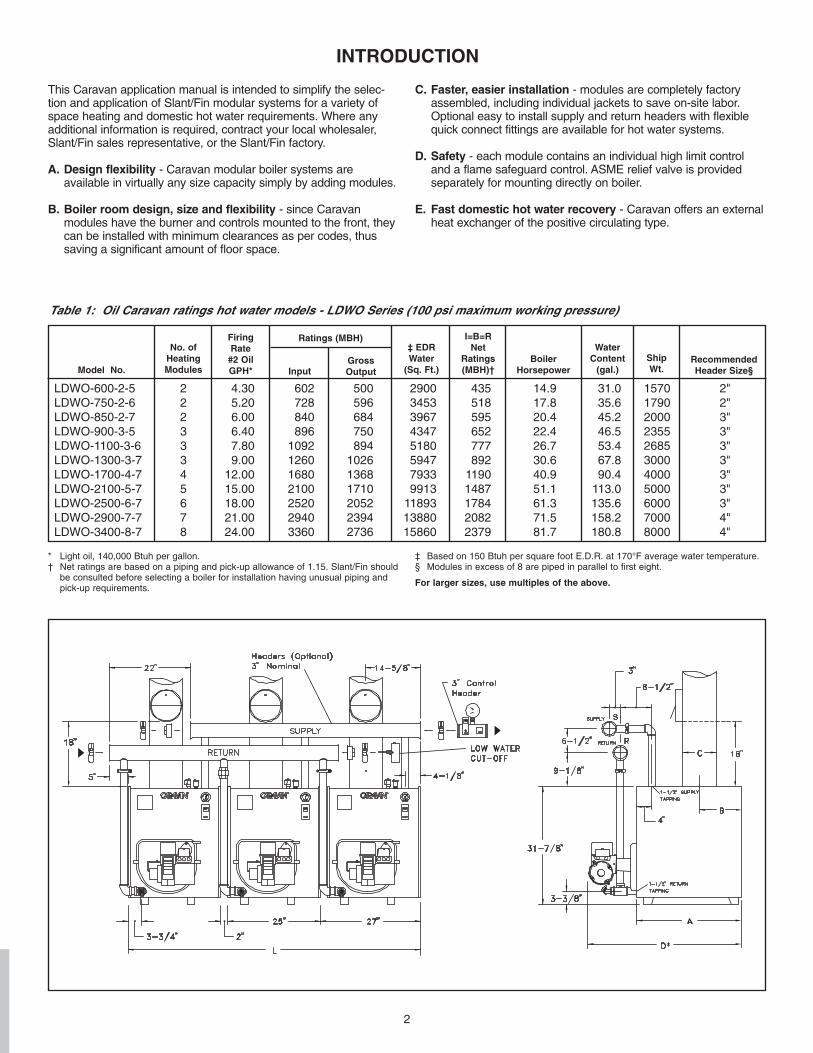
Optional Piping Method - Primary/SecondaryWhen applying oil-fired Caravan boilers to a low temperaturewater system care should be taken to maintain 130˚F return water temperature inside the Caravan boiler. One way to accomplishthis is to design the boiler using primary/secondary piping.
Slant/Fin recommends a minimum of 15˚F system water temperature rise across modules that are firing. If the desiredtemperature rise is lower than a primary/secondary arrangementshould be used, either for the whole modular boiler or using a
multiple boiler system as described below. The 15˚F minimumtemperature rise can be maintained in the modules withoutaffecting the system water.
1. Primary/secondary piping may be applied to a Caravan modular boiler system as demonstrated on Figure 4. In this type of application the modular boiler is contained within the primary loop. However, this is still a modular boiler, if it hasno valves between the modules.
2. Primary/secondary piping may also be used on each individual “module”, please see figure 5. In this arrangement the Caravan is no longer a “modular” boiler, it is now a “multiple” boiler
system. In a multiple boiler system each module is actually a standalone boiler and each boiler should be equipped with a manual reset hi limit and low water cutoff. Certain local codes also require a minimum distance between each boiler.
Please remember to always follow code requirements applicableto the building that the boilers are being installed in.
Most Caravan systems are applied as a modular boiler, not as amultiple boiler. A modular boiler system is efficient, easy to main-tain and very dependable. When a multiple boiler is used thereare additional circulators, manual reset hi limits and low water cut-offs to install and maintain.
Some people believe a multiple boiler system is more efficientbecause water flows through only those units that are firing. Theymay think water flowing through modules not firing leads to energyloss in those modules. However, we must remember a boiler heatexchanger is designed to absorb heat from high temperature com-bustion and transfer it to low temperature water (certainly below250˚F water). Boilers do not make good “convectors” and very lit-tle heat is passed through the venting of a module not firing. Oil-fired modules experience very low airflow through the heatexchanger when not firing.
In most applications we recommend a step or stage controller,that modulates system water temperature, be used on a Caravansystem. These controls ensure the number of modules firingequals the actual demand for heat. Slant/Fin’s step controllers arethe SC-3 and SC-9 model controls. Please see the Control sec-tion of this manual for more information on these controls.
ModuleFlow Rate/
Module GPMPressure
Drop/Module PSI
7-section 34 0.30
6-section 30 0.30
5-section 25 0.30

5
Figure 2. Typical space heat piping – For primary circulation only.
Figure 3. Typical space heat and domestic piping – For primary circulation only.
6
Figure 4. Primary/Secondary piping of modular boiler.
Figure 5. Primary/Secondary piping of multiple boiler.

7
Figure 7. Supply and return piping locations for space heat with domestic hot water
Figure 8: Instantaneous tankless coil—two temperature with recirculation
Figure 9: Storage tank from tankless coil with recircula-tion locations for space heat with domestichot water
SUGGESTED DOMESTIC HOT WATER PIPING
Minimum flow rate formula:Minimum flow rate through modules =
Gross output (MBH)20,000
Note: A water flow proving deviceis recommended on allCaravan systems.
Figure 6. Recommended boiler piping for variable volume zone circulation
RECOMMENDED SYSTEM PIPING AND WATER FLOW

8
EQUIPMENT INCLUDEDLDWO SERIES –– Hot Water Models• Pre-assembled heat exchangers with built-in air separators• Insulated baked enamel jacket.• Flue collector.• Draft regulator.• Flame retention oil burner with nozzle and CAD cell.• Primary burner control.• Temperature limit.• Flue brush.• Module temperature and pressure gauge.• System pressure and temperature gauge.
(unmounted-1 per system).• Pressure relief valve (unmounted-1 per module).• Control header (unmounted-1 per system, up to 8 modules).
OPTIONAL EQUIPMENT• Headers.• Control System.
Figure 10. Oil Caravan—optional header assembly for all models LDWO and LWDF hot water Caravan systems.
*Building piping must be rigidly secured so it cannot move where connected to headers.
NOTE:Shown reverse return (Preferred). For direct return,header assembly piping connections may be made atthe same end of the boiler bank, not as shown.
Some governing agencies do not allow compressiontype couplings. Consult your local code requirements.
3'' RETURN HEADER WITH 11/2'' STUBS
(3 MODULE)
* 3'' BUILDING PIPING
(BY OTHERS)
11/2'' X 34'' SQUARE NIPPLE
11/2'' X 30'' NIPPLE
CAST END CAP WITH 3/4'' TAPPING.
SUPPLY OR RETURN. FOR USE WITH LWCO.
3'' SUPPLY HEADER WITH 11/2'' STUBS
(3 MODULE)
11/2'' X 4'' NIPPLE
3'' PIPE X 20'' (BY OTHERS)
11/2'' UNION
11/2'' X 11/2'' X 11/2'' TEE
11/2'' X 3/4'' BUSHING
3/4'' DRAIN VALVE
11/2'' X CLOSE NIPPLE
11/2'' ELBOW
3'' SUPPLY HEADER WITH 11/2'' STUBS
(2 MODULE)
*3'' BUILDIING PIPE CONNECTION
1/2'' PRESSURE TEMPERATURE
GAUGE
1/2'' WELLS
3'' FLEX JOINT (SEE DETAIL "A")
11/2'' ELBOW
11/2'' X 15'' NIPPLE
CAST END CAP
3'' RETURN HEADER WITH 11/2'' STUBS
(2 MODULE)
3'' FLEX JOINTS (SEE DETAIL "A")
11/2'' X 8'' SQUARE NIPPLE
11/2'' FLEX JOINT (SEE DETAIL "A")
11/2'' X 4'' NIPPLE
CONTROL HEADER 3'' x 1/2'' x 1/2'' x 1/2''
150 psi 275˚ F
Pressure/Temp Rating for flex joint fittings

9
BOILER ROOM DESIGNCaravan modular boiler systems allow better utilization of floorspace and permit future expansion with minimum cost. Caravanmodules are hand truckable, fit through doorways and often maybe installed around an existing inoperative boiler. They can begrouped in heating module batteries of single, multiple or angularrows. Oil-fired boiler systems consisting of 9 or more modulesshould be piped in parallel in two or more batteries. Illustratedbelow are typical boiler room layouts and dimensional data on thesize requirements of oil-fired hot water boilers.
BOILER ROOM AIR SUPPLYTo ensure safe, efficient operation, the modular boiler system mustbe supplied with sufficient air to support complete combustion,replacing air entering draft dampers or draft hoods and ventilatingthe boiler room or areas. For additional information, not listedbelow, see ANSI,Z223.1, section 5.3.3.
INSTALLATION IN ENCLOSED BOILER ROOM REQUIRESTWO UNOBSTRUCTED OPENINGS FOR PASSAGE OFAIR INTO THE BOILER ROOM:
1. Air drawn horizontally from outdoors DIRECTLYthrough an outside wall; one louvered opening near the floor (below burner air inlet) and one louvered opening near the ceiling (above the highest draft regulator), each opening with a minimum FREE air passage area of 1 square inch per 4000 BTUH of total system input.
2. Air drawn horizontally from outdoors through HORIZONTAL DUCTS; one opening near the floor (below
burner inlet) and one opening near the ceiling (abovethe highest draft regulator), each open-ing with a minimum FREE air passagearea of 1 square inch per 2000 BTUH of total systeminput.
3. Air drawn VERTICALLY from outdoors; one opening at the floor and one opening at the ceiling, each opening with a minimum FREE air passage area of 1 square inch per 4000 BTUH of total system input.
4. Air drawn from inside the building; one opening near the floor (below burner inlet) and one opening near the ceiling (above the highest draft regulator), each opening with a minimum FREE air passage area of 1 square inch per 1000 BTUH of total system input.
IF BOILERS ARE INSTALLED ADJACENT TO OTHER FUELBURNING EQUIPMENT, THE AREA OF FREE OPENINGS MUSTBE APPROPRIATELY INCREASED TO ACCOMMODATE THEADDITIONAL LOAD.
UNLESS PROPERLY CONTROLLED, AVOID THE USE OFFORCED VENTILATION, SINCE IT CAN CREATE AN UNDESIRABLE PRESSURE DIFFERENTIAL BETWEEN BOILER ROOM AND AIR SOURCE.
Figure 11. Correct location of combustion-air supply ducts

10
Figure 12. Typical layouts for oil-fired systems
* Caravan can be installed as close as 1" from the wall, local codes permitting. However, 24" is recommended for service inspection access.
∆ See Figure 1 dimensions A and D.

11
VENTING A OIL-FIRED SYSTEMA boiler venting system provides draft and an escape path for theproducts of combustion. In a venting system for an oil-firedCaravan, there are three major components: a riser with draft reg-ulator for each module, a breeching manifold, and a chimney.
Sometimes the venting system for a boiler plant has to bedesigned to compensate for inadequate chimney conditions. Amechanical draft inducer, properly sized and installed, can usuallyincrease chimney capacity sufficiently to provide proper venting.Where a draft inducer is called for, consult local codes and therecommendations of the mechanical draft inducer manufacturer.Normally, a draft proving device is necessary to permit operationof the boilers only when adequate draft exists.
It is important to note that when considering a mechanical draftinducer, the boiler room air supply requirements must beincreased. Consult the draft inducer manufacturer for this information.
Draft RegulatorThe draft regulator compensates for excessive draft that can becaused by varying weather conditions. The regulator should be ofthe barometric-draft type. Once adjusted for a particular ventingsystem, this type regulator automatically compensates for excessive draft to assure optimum operating efficiency.
BreechingBreeching is a term used to describe a manifold(s) that connectsindividual boiler modules to a chimney. Breeching is usually constructed of sheet metal having a smooth interior surface withall joints made tight against leakage. The layout of a particularboiler room may require that the modules be arranged in"batteries" with rows either parallel or at right angles. Minimumbreeching sizes are given in Table 3.
To avoid creating turbulent air patterns in the breeching, it is suggested that individual boiler vent pipes be connected to thebreeching as indicated in Figure 13.
The breeching manifold should extend into, but not beyond, thechimney liner. Round breeching is preferable to rectangularbreeching.
ChimneyCaravan oil-fired modular boilers operate efficiently with masonryor prefabricated chimneys. This latter type of chimney constructionis generally the least expensive.
Minimum chimney sizes and heights are given in Table 4. In addition, the chimney should be high enough to minimize theeffects of turbulent winds and high pressure areas common nearroof-top obstructions. The National Board of Fire Underwriters recommends that the chimney should extend 3 feet above theroof and be 2 feet higher than any obstruction within 10 feet (fig-ure 13). The use of a vent cap where permitted by code givesadditional protection against adverse wind conditions and precipi-
tation.
Sizing Horizontal Breeching Connectors and Chimneys forOil-Fired SystemsHorizontal breeching connectors shall be constant sized. Thechimney and the horizontal breeching connector are sized usingtable 3.When there are multiple banks of boilers, the horizontal breechingconnector for each bank is sized using table 3. To size the com-mon horizontal breeching connector, add up the total input andrefer to table 3 to size.The minimum chimney will be equal to the size of the largest hori-zonatl breeching section connected to it.
LDWO-600-2-5 2 11" 84 4'8"LDWO-750-2-6 2 12" 101 4'8"LDWO-850-2-7 2 13" 115 4'8"LDWO-900-3-5 3 13" 123 7'1"LDWO-1100-3-6 3 14" 148 7'1"LDWO-1300-3-7 3 15" 170 7'1"LDWO-1700-4-7 4 16" 189 9'6"LDWO-2100-5-7 5 18" 233 11'11"LDWO-2500-6-7 6 19" 277 14'4"LDWO-2900-7-7 7 21" 320 16'9"LDWO-3400-8-7 8 22" 365 19'2"
Model No. *No. of
ModulesBreechingDiameter
MinimumArea
(sq.in.)Breechin
g
* Dual fuel prefix = LWDF.Notes:1. For breeching and chimney sizing over 8 modules, consult factory.2. Breeching length should be as short as possible. Measurement from the
base of the vertical vent to the nearest connected appliance should be limited to 10' or 50% of the total vent height, whichever is greater.
Table 3. Breeching dimensions for oil-fired systems —LDWO Series
LDWO-600-2-5 2 11" 93⁄4" X 93⁄4" 20'LDWO-750-2-6 2 12" 91⁄2" X 131⁄2" 20'LDWO-850-2-7 2 13" 131⁄4" X 131⁄4" 20'LDWO-900-3-5 3 13" 131⁄4" X 131⁄4" 20'LDWO-1100-3-6 3 14" 131⁄4" X 131⁄4" 20'LDWO-1300-3-7 3 15" 13" X 17" 20'LDWO-1700-4-7 4 16" 13" X 17" 25'LDWO-2100-5-7 5 18" 163⁄4" X 163⁄4" 25'LDWO-2500-6-7 6 19" 161⁄2" X 201⁄2" 25'LDWO-2900-7-7 7 21" 201⁄4" X 201⁄4" 25'LDWO-3400-8-7 8 22" 201⁄4" X 201⁄4" 25'
Model No. *No. of
ModulesDia.
Inches
RectangularL x WInches
MinimumHeightFeet
Chimney Liner Inside Dim. †
* Dual fuel prefix = LWDF.† Dimensions shown are from ASHRAE Guide Equipment Handbook. Also
select inside liner dimensions to give area as great or greater than shown inthis table. Chimney height is measured from the center line of the breechingto the top of the chimney. Chimney dimensions are approximate, with nomanifold elbows or tees; and good vent construction practices. Field conditions vary. It is doubtful that the chimney dimensions shown here will be suitable for all applications. Consult the 2000 ASHRAE Equipment Handbook and Chimney Manufacturers Sizing Handbook.

12
Figure 13. Suggested venting system constructions

13
FUEL OIL STORAGE FACILITIESLocal codes usually govern the installation of fuel oil storage facilities. However, for areas where no rules have been established,the following information can provide assistance to the systemdesigner.
Storage tank sizingWhen calculating minimum fuel oil storage capacity, several variables must be considered. These include: maximum fuel consumption rate, storage space limitations, availability, distancefrom source of supply, and method of delivery (truck or railroad tankcar). Large storage tanks, of course, cost more than smaller onesbut the cost is not proportional (e.g., a 10,000 gal. tank does notcost twice as much as a 5,000 gal. tank). And larger tank capacityallows oil purchases usually at lower per gallon rates.
Generally, the storage tank should hold enough oil to sustain continuous operation for 10 days (plus an additional 10% margin toallow for suction stub clearance).
To determine the minimum storage requirement, proceed asfollows:
a) Refer to Table 1 to find the maximum hourly oil consumption(GPH) of the system being installed.
b) Multiply the maximum hourly consumption by the probable maximum daily hours of operation to achieve maximum daily consumption.
c) Multiply the maximum daily consumption by 10 (days) and add10% to obtain the MINIMUM storage capacity.
Requirements for fuel oil storage tanks.Data in this section is based on the use of steel storage tanks.Where no local codes apply, take the following data into consideration.
a) Inside tanks are usually located in the lowest part of the building.When supply and return lines are piped through the top of thetank, spillage is minimized in the event of leaks.
b) Unenclosed tanks should be at least 7 feet from any openflames or fires.
c) Most fire codes prohibit unenclosed inside tanks exceeding 275gallons each. Where multiple tanks are installed, the total stor-age capacity should not exceed 550 gallons unless vaulted.
d) If inside tanks are properly enclosed, the maximum storagecapacity can be increased to 5,000 gallons in non-fire-resistantbuildings, and to 15,000 gallons in fire-resistant structures.
NOTE: An enclosure shall consist of walls constructed of 6" reinforced concrete or 8-inch thick masonry with the space between tank and walls filled with sand. If floor above has a load-bearing capacity of 150 lbs./sq. inch or greater and is constructed of fire-resistant material, 1 foot of sand fill over the tank is sufficient. If not, a 5-inch concrete slab, or equivalent, must be employed. An alternative method is to pour a 6-inch thick concrete enclosure directly over the tank (no air spaces).
e) Underground tanks (Figure 14) are to be buried at least 2 feetbelow grade.
f) Tanks buried beneath buildings ALWAYS require 4-inch reinforced concrete slab covers that extend 1 foot beyond tank inall directions.
g) Fiberglass and/or double-walled tanks may be required. Checkyour local codes. Underground metal tanks should be paintedwith heavy asphaltum, rust-resistant paint or be of double walledconstruction (check local codes). DO NOT install tank in bed ofcinders (cinders contain sulphur, which becomes corrosive whenwet).
NOTE: Before installing underground tanks, check local surfacewater conditions. Where potential problems exist, concreteanchors should be provided.
FUEL OIL DELIVERY SYSTEMSFOR SINGLE FUEL BURNERSGeneralThree methods for delivering oil to the individual burners aredescribed herein. These methods are chosen to provide tempered,filtered and air-free oil to the individual burners. Consistent oil quality will optimize burner operation over longer periods.
There are variations to the methods described herein which, ifapplied properly, will result in acceptable operation. These methodsare for reference only. Local codes vary. It is important to check allcodes for compliance.
Information herein has been compiled using data from industrysources, including companies such as Mitco, Webster, Suntec andTuthill. For additional information on these products, contact the representative in your area.
MFG data and safety codes vary with regard to maximum fuel unitinlet pressure. Pay particular attention to the gravity oil head. Besure to add oil pressure reducing valves in the event that codes orMFG data will be exceeded. 5 psi is equivalent to approximately 12feet in height. (See "H" dimension.)
Storage tank above burners (Figure 15)A simple one pipe connection from the supply tank to each burnerhelps to eliminate air in the oil line and tempers the oil in the pipeas it travels slowly to the burners.
FUEL OIL PIPING
Figure 14. Typical example of properly installed underground fuel tank

14
This method maintains consistent fuel oil quality to the individualburners and therefore decreases the frequency of maintenance andservice. When a component breakdown occurs in a burner or in thesupply system, the trouble is easily found and service is restoredquickly.
Storage tank below burners and gravity tank aboveburners (Figure 16)Oil is automatically and constantly maintained in the supply tank ata level sufficient to meet all burner needs. As oil is used, the pressure drop is sensed by a pre-set automatic pressure switch,which signals the booster pump to restore proper level. There is nopractical limit on the height or distance that the motorized pump candeliver oil to the supply tank.
The great advantage of the booster pump along with a gravity tankis that it accomplishes its purpose in the most simple and directmanner. This results in the most economical installation, with theshortest possible runs of pipe and wire. It also enables the installerto adapt with ease to almost any building configuration. A simpleone pipe connection to each burner helps eliminate air in oil linewith constant flow of fuel and tempers the oil.
Simplicity of operation of the individual burner decreases thechances that service will be needed. When a component break-down occurs in a burner or in the supply system, the trouble is easi-ly found and service is restored quickly.
Figure 15. Storage tank above burners
Figure 16. Storage tank below burners

1' 118 99 328 2762' 113 95 313 2633' 107 90 298 2504' 102 86 283 2375' 96 81 268 2256' 91 76 253 2127' 86 72 238 2008' 80 67 222 1879' 75 61 207 17410' 69 58 192 16111' 64 54 177 14812' 58 49 162 13613' 53 44 147 12314' 47 40 131 11015' 42 35 116 98
Two PipeLift Ht.
1/2" O.D. Tubing
A B
5/8" O.D. Tubing
A B
A = B82 Series Suntec Pump 63 GPH gear capacity.B = B89 Series Suntec Pump 75 GPH gear capacity.
Table 8. Line Length for Two-Stage Fuel Unit
15
Components usually required are a motorized booster pump of sufficient capaci-ty, gravity tank and mounting hardware, automatic oil level pressure switch, vac-uum breaker and necessary check valves and fittings. Additional information canbe obtained from Mitco Manufacturing, Hicksville, New York.
Duplex booster pumps are desirable to provide standby capability, in the eventof booster pump failure.
Sizing booster pumpTo determine the correct size of a booster pump:
a) Using Table 1, find maximum total firing rate of the boiler system beinginstalled.
b) Find the vertical and horizontal dimensions of the booster pump's suction line.c) Make sure the suction line lift and length are with capabilities of typical boost-
er pumps. Refer to Table 5. (This data is based on Suntec models BH-1030Mat 30 GPH, and BH-1050M at 50 GPH or equivalent.)
NOTE: If lift is excessive (max. 6" Hg one stage, 15" Hg two stage), contactpump manufacturer with exact requirements. If total length is too long, increasesuction line diameter.
d) Using Table 6, find correct supply line size.
FUEL OIL DELIVERY SYSTEMSFOR DUAL FUEL BURNERS
GENERALDual fuel burners are shipped separately and must be field mounted andwired. Connections to Slant/Fin control systems can be found in the controlsection of this manual.
Burner set-up and mounting instructions are shipped with each dual fuel burn-er. The installer must follow these instructions.
Dual fuel burners require specific types of fuel oil piping systems. The fuel oilpump is active during gas and oil operation. Since no oil flows to the burnerduring gas operation, a two pipe system keeps fuel oil in circulation, prevent-ing pump overheating and thermal expansion.
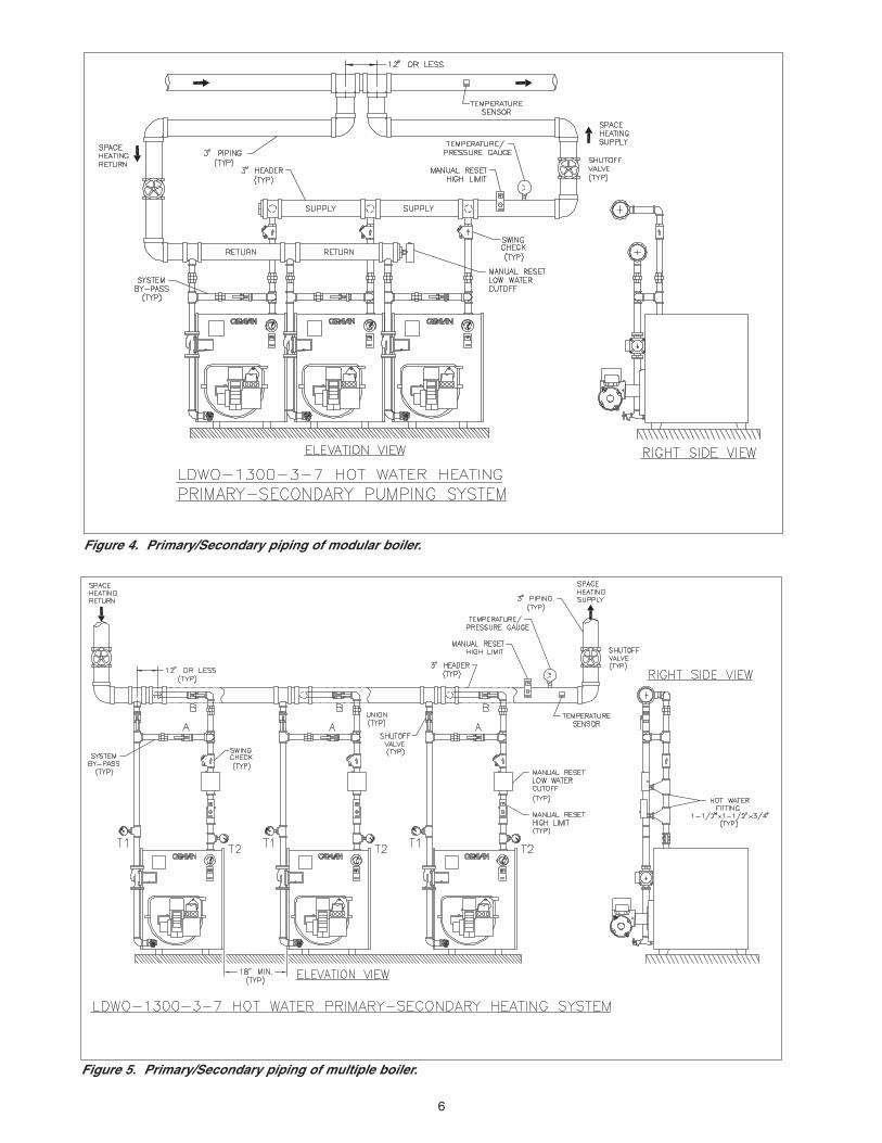
Figures 18 and 19 illustrate two types of two pipe fuel oil delivery systems fordual fuel burners.
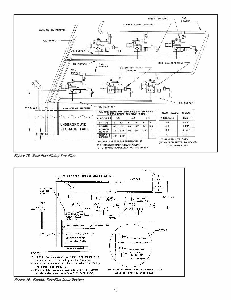
If the system is gravity feed, or if the lift is 12' or less, a single stage pump maybe selected. If the lift is 18' or less, then a two stage fuel pump should be used.If the lift is more than 18', use a pseudo two pipe loop system (Figure 15).
TWO PIPE SYSTEM (Figure 18)An important factor to consider in a two pipe system is the line size whichdepends on the maximum line length and the total oil volume. The gearcapacity of the pump is normally quite high compared to the pump's markedcapacity. For example, an "A" pump marked for 3 GPH could have a gearcapacity of 17 GPH at 3450 RPM.
For a Caravan system, it is ideal to have individual supply and return fuel linesfor each boiler. In practice, one can opt to have not more than 3 boilers on asingle supply or suction line and a common return for 6 to 9 boilers. (Figure 18)
Table 8 is the calculated line lengths for two types of "B" pumps with differentgear capacities. For example, if the lift is 10', the furthest boiler 150' and thefuel oil pump is two stage, of type B89 series, then the corresponding linelength from the table is 161' for 5/8" tubing.
NOTE: NFPA requires that the pump inlet pressure not exceed 3 psi. Therefore, when oil is fed by gravity from above the pump,the height should not be more than 8' from the pump to the top offuel oil supply. If it is more than 8', then one way to protect thepump is to have a vacuum operated safety valve (OSV) on eachfuel unit.
PSEUDO TWO PIPE LOOP SYSTEM (Figure 19)Another way to prevent overheating and thermal expansion of theoil while the unit is running on gas for extended periods, is to usea pseudo two pipe loop system (Figure 15). This system uses a booster pump to circulate the oil from the tank to a header thatfeeds the burners. Excess oil is fed back to the tank. Generally, a1/2" fuel line should handle most installations within 200' whenusing a type "A" pump. A duplex pump-motor boost system shouldbe wired to run for oil as well as for gas. Whenever a burner (regardless of fuel) is running, one of the duplex pump motorsshould be activated and another pump motor should serve as anautomatic backup
Figure 17.Wiring diagram for
gravity feed booster- pump operation
0 - 7' 100' 63'8 - 10' 80' 53'11 - 13' 63' 41'14 - 15' 52' 34'
VerticalLift (2)
Firing Ratesup to 30 GPH (5)
Firing Ratesup to 50 GPH (6)
Maximum Total Suction Line Lengths (3)1/2" O.D. copper tubing (4)
Table 5. Maximum booster pump suction line length (1)
25' 1⁄2" O.D. tube 1⁄2" O.D. tube75' 1⁄2" pipe 1⁄2" pipe200' 3⁄4" pipe 3⁄4" pipe
Total LengthMaximum
Firing Ratesup to 30 GPH (5)
Firing Ratesup to 50 GPH (6)
Table 7. Boiler feed line sizes (9)
Up to 30 GPH (5) 300' 800' 2500'Up to 50 GPH (6) 175' 350' 1500'Supply Line Size 1⁄2" O.D. tube 1⁄2" pipe 3⁄4" pipe
Firing Rate Maximum Total Supply Line Length (8)
Table 6. Supply line sizes for high-volume fuel oil delivery systems (7)
(1) Defined as the connection distance between storage tank and inlet of booster pump.(2) Height of booster pump inlet above bottom of storage tank. If higher lift is
needed, contact booster pump manufacturer with exact requirements.(3) Total suction length equals vertical lift plus horizontal distance between suction
line connection at storage tank and inlet of booster pump.(4) 5/8" tubing allows maximum horizontal distance between supply tank outlet
and booster pump inlet to be safely increased by 250%.(5) Maximum fuel oil consumption rate with Suntec BH-1030M pump.(6) Maximum fuel oil consumption rate with Suntec BH-1050M pump.(7) Supply line is defined as the connection between the outlet of the booster
pump and the inlet of the supply tank.(8) Total supply line length equals vertical lift plus horizontal distance between
booster pump outlet and supply tank inlet.(9) Boiler feed line is defined as the connection between the gravity feed tank and
the furthest burner.
16
Figure 18. Dual Fuel Piping Two Pipe
Figure 19. Pseudo Two-Pipe Loop System

17
THE BOILER STAGING CONCEPTThe heart of the Caravan boiler plant is a temperature-actuatedcontrol system that automatically stages only those boiler modules needed to meet the heating demand in a given period,thereby conserving fuel.
In a staging control system, each stage ordinarily activates oneboiler module. With appropriate wiring, multiple modules can begrouped within a stage.
During a fluctuation in heating requirements, a large central boilercycles on and off to match heat output to building demand. Astaged modular boiler system, on the other hand, will energizeonly as many modules as the system load requires. Only onestage cycles at a time. The other stages remain off or operatecontinuously, thereby performing at peak efficiency. For example,in a 10 module boiler system, with the heating load at 61% ofcapacity, six of the modules operate continuously at peak efficiency. Fractional heating requirements are supplied by theseventh "cycling" module, while the remaining three modules are"off." This is in contrast to a single large central boiler that simplycycles on and off, resulting in lower efficiency.
Over-sizing is a major factor in poor system efficiency. Most ofthe time a single central boiler is oversized. Historical datashows that many single central boilers are considerably over-sized even at the outdoor temperature for which they weredesigned. Modular boiler systems are not oversized by more thana portion of one module, regardless of the load.
The Caravan control system automatically compensates for seasonal temperature changes. It energizes more or fewer modules depending on changes of outside temperature, systemwater temperature, or both. Modules save energy by operating inlong cycles at full-rated output and maximum efficiency.
CONTROL SYSTEM SELECTIONSlant/Fin offers two controls to step fire a hot water Caravan sys-tem. The SC-3 and SC-9 controls fulfill a wide range of applica-tions. They control the boiler system and are not intended to bethe sole building temperature control. They do not replace zoningthe system or the thermostats that control these zones.
SC-3 Control
The SC-3 control allows up to 3 stages in a Caravan system.Generally each stage controls 1 module. However, it is possibleto have more than 1 module activated with each stage.
Standard programmable features include: system activation orde-activation based on outdoor temperature; minimum target supply water temperature; adjustable design target supply watertemperature; adjustable delay between stages; adjustable outdoor temperature and indoor design temperatures.
The view menu on the control includes error messages, actualoutdoor air temperature, actual supply water temperature, target supply water temperature and running time for each stage.
This control can be programmed as follows:
1. Outdoor reset: The supply water temperature is automatically adjusted up or down based on outdoor temperature. The control automatically controls the number of modules required to maintain required supply water temperature.
2. Setpoint temperature: The control can be programmed to maintain a set supply water temperature. The control automatically controls the number of modules activated to maintain the setpoint temperature.
SC-9 Control
The SC-9 control allows up to 9 stages of operation for spaceheating, domestic water or combination, in a Caravan system.Generally each stage controls 1 module. However, it is possibleto have more than one module activated with each stage.
Standard programmable features include: system activationor de-activation based on outdoor temperature; minimum targetsupply water temperature; adjustable design target supply watertemperature; adjustable delay between stages; adjustable outdoor and indoor design temperatures; delay to allow combustion air damper to open; ability to provide equal run timerotation of boiler modules; fixed lead of a module when Caravansystem activates; first on/last off or first on/first off for modules;control of primary circulator and periodic exercising of primarycirculator when system is inactive.
The view menu on the control includes error messages, actualoutdoor air temperature, actual supply water temperature, target water temperature, running time for each stage and thedifference between supply water and return water temperatures.
The SC-9 can be programmed as follows:
1. Outdoor reset: The supply water temperature is automatically increased as outdoor temperature decreases and decreased as outdoor temperature increases. The control activates only the number of stages required to maintain the required supply watertemperature.
2. Setpoint temperature: The control maintains a set supply water temperature. The control activates only the number of stages required to maintain the setpoint temperature. Setpoint temperature may be used for a Caravan system
that is dedicated for use as volume water heating.
3. Domestic hot water: The domestic hot water controls override the SC-9 control for only those modules used to heat the domestic hot water. The modules for domestic hot water are isolated from space heating system until demand for domestic hot water is satisfied. The modules not used for domestic hot water heating remain under control of SC-9 control.
Slant/Fin offers domestic hot water control packages and external tankless heaters as options for use with the SC-9 control.
CONTROLS
18
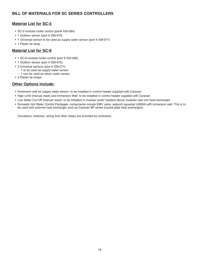
BILL OF MATERIALS FOR SC SERIES CONTROLLERS
Material List for SC-3
• SC-3 modular boiler control (part# 435-084)
• 1 Outdoor sensor (part # 339-070)
• 1 Universal sensor to be used as supply water sensor (part # 339-071)
• 1 Plastic tie strap
Material List for SC-9
• 1 SC-9 modular boiler control (part # 435-085)
• 1 Outdoor sensor (part # 339-070)
• 2 Universal sensors (part # 339-071)- 1 to be used as supply water sensor- 1 can be used as return water sensor
• 2 Plastic tie straps
Other Options include:
• Immersion well for supply water sensor: to be installed in control header supplied with Caravan
• High Limit (manual reset) and Immersion Well: to be installed in control header supplied with Caravan
• Low Water Cut-Off (manual reset): to be installed in modular boiler headers above modules cast iron heat exchanger
• Domestic Hot Water Control Packages: components include EMV valve; setpoint aquastat L6006A with immersion well. This is to be used with external heat exchanger such as Caravan BP series brazed plate heat exchangers.
Circulators, switches, wiring and other relays are provided by contractor.

19
FIELD WIRING AT MODULES

20
SC-3 SYSTEM WIRING DIAGRAM

21
SC-3 LADDER WIRING DIAGRAM

22
SC-9 SPACE HEATING WIRING DIAGRAM

23
SC-9 SPACE HEATING LADDER WIRING DIAGRAM
24
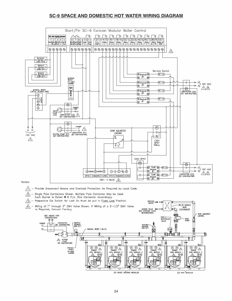
SC-9 SPACE AND DOMESTIC HOT WATER WIRING DIAGRAM

25
SC-9 SPACE AND DOMESTIC HOT WATER LADDER WIRING DIAGRAM

26
WARRANTY INCLUDES:FIRST YEAR: Repair or replacement in accordance withwarranty service procedure, for a period of one year afteroriginal installation, of all parts found to be defectively manufactured.
WARRANTY INCLUDES:SECOND THROUGH FIFTH YEAR: Repair or replacementfor the second through fifth year after original installation, ofcast iron heat exchanger found to be defectively manufac-tured, at no cost for the replacement part. The repaired orexchanged part will be warranted for only the unexpired portion of the original warranty.
This warranty extends only to boilers in space heating applications. See “Additional Warranty Terms” section formore details.
Warranty extends only to boilers which have been properlyinstalled, operated and maintained in accordance withSlant/Fin installation instructions and all applicable codes.Warranty applies only if the boiler has remained at all timesin the location at which it was originally installed. Slant/Finmakes no express warranties other than the warranties contained herein.
WARRANTY EXCLUDES:All labor charges incurred by any person in connection withthe examination, removal, and repair of parts claimed to bedefective and the installation of replacement parts.
The part claimed to be defective shall be returned toSlant/Fin. The cost of shipment to Slant/Fin is borne by theconsumer.
Damage caused by water that contains excessive lime,calcium, or other contaminants.
Boilers operated with combustion air that may be contaminated by chemicals or improper fuel additives.
Improper burner adjustments, control settings or maintenance procedures.
NOTE: Boilers are to be used in closed systems. Any application that causes significant quantities of fresh makeup water to enter the system is not permitted. Such applications can be met with a heat exchanger that willmaintain the boilers in a closed system.
AFTER FIRST YEAR, WARRANTY EXCLUDES:All boiler components other than a cast-iron heat exchanger,such as, sheet metal base, jacket, insulation, combustionchamber, tankless heater exhaust and air inlet piping, burnerenclosure, mixing elbow, gas and air orifice, blower assem-bly, air filter and electrical and mechanical components furnished to Slant/Fin by other manufacturers, such aspumps, relays, controls, gauges, etc.
PROCEDURE FOR WARRANTY SERVICE:For warranty service, provide the person who installed yourSlant/Fin boiler with the following information: boiler modelnumber and serial number (from the boiler rating plate) andthe date of installation. That person will notify the Slant/Finwholesaler from whom the boiler was purchased.
Part(s) claimed to be defective must be returned throughtrade channels and replacement part(s) will, if warranty conditions are met, be provided by Slant/Fin through thewholesaler.
If there are any questions about the coverage of this warranty, please contact Slant/Fin at the address shownbelow.
LIMITATIONS ON IMPLIED WARRANTIES AND DAMAGES:Slant/Fin assumes no liability for damages or unsatisfactory performance of any kind which is a result of improperinstallation.
Slant/Fin's sole obligation in the event of a breach of anyimplied warranty (including, but not limited to, implied warranties of merchantability and fitness for a particular purpose) is limited to repair or replacement, and all suchwarranties are limited in duration to the period of time afterthe date of original installation as stated above.
This warranty does not cover claims for incidental or consequential damages resulting from a breach of anyexpress or implied warranty or any other reason.
Some states do not allow limitations on how long an impliedwarranty lasts or the exclusion or limitation of incidental orconsequential damages. So the above limitation or exclusion may not apply to you.
THIS WARRANTY GIVES YOU SPECIFIC LEGALRIGHTS AND YOU MAY ALSO HAVE OTHER RIGHTSWHICH VARY FROM STATE TO STATE.
Slant/FinLimited Five-Year Warranty
for Caravan Modular and Individual Commercial Application Cast-iron Hot Water Boilers in Space Heating Applications.
Technical Service Department
Slant/Fin Corporation, 100 Forest Drive at East Hills, Greenvale, N. Y. 11548 • (516) 484-2600

27
CARAVAN SYSTEM RATING PLATE
System rating plate format for Caravan modular boiler system. System rating plates are available upon request using the form on the back cover.
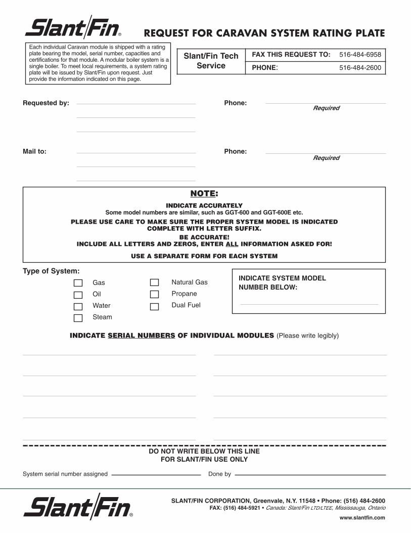
REQUEST FOR CARAVAN SYSTEM RATING PLATE
NOTE:INDICATE ACCURATELY
Some model numbers are similar, such as GGT-600 and GGT-600E etc.
PLEASE USE CARE TO MAKE SURE THE PROPER SYSTEM MODEL IS INDICATED COMPLETE WITH LETTER SUFFIX.
BE ACCURATE!INCLUDE ALL LETTERS AND ZEROS, ENTER ALL INFORMATION ASKED FOR!
USE A SEPARATE FORM FOR EACH SYSTEM
Slant/Fin TechService
FAX THIS REQUEST TO: 516-484-6958
PHONE: 516-484-2600
Requested by:
Mail to:
Phone:
Phone:
Required
Required
SLANT/FIN CORPORATION, Greenvale, N.Y. 11548 • Phone: (516) 484-2600FAX: (516) 484-5921 • Canada: Slant/Fin LTD/LTEE, Mississauga, Ontario
www.slantfin.com
Each individual Caravan module is shipped with a rating plate bearing the model, serial number, capacities and certifications for that module. A modular boiler system is a single boiler. To meet local requirements, a system rating plate will be issued by Slant/Fin upon request. Just provide the information indicated on this page.
Type of System:
Gas
Oil
Water
Steam
Natural Gas
Propane
Dual Fuel
INDICATE SYSTEM MODELNUMBER BELOW:
INDICATE SERIAL NUMBERS OF INDIVIDUAL MODULES (Please write legibly)
DO NOT WRITE BELOW THIS LINEFOR SLANT/FIN USE ONLY
System serial number assigned Done by