Embed Size (px)
Citation preview
Wet Abrasive Blasting Systems
„Manual“ 201099 torbo® S080 to torbo® M120
1/2001, english

Manual torbo® S / M Seite 3
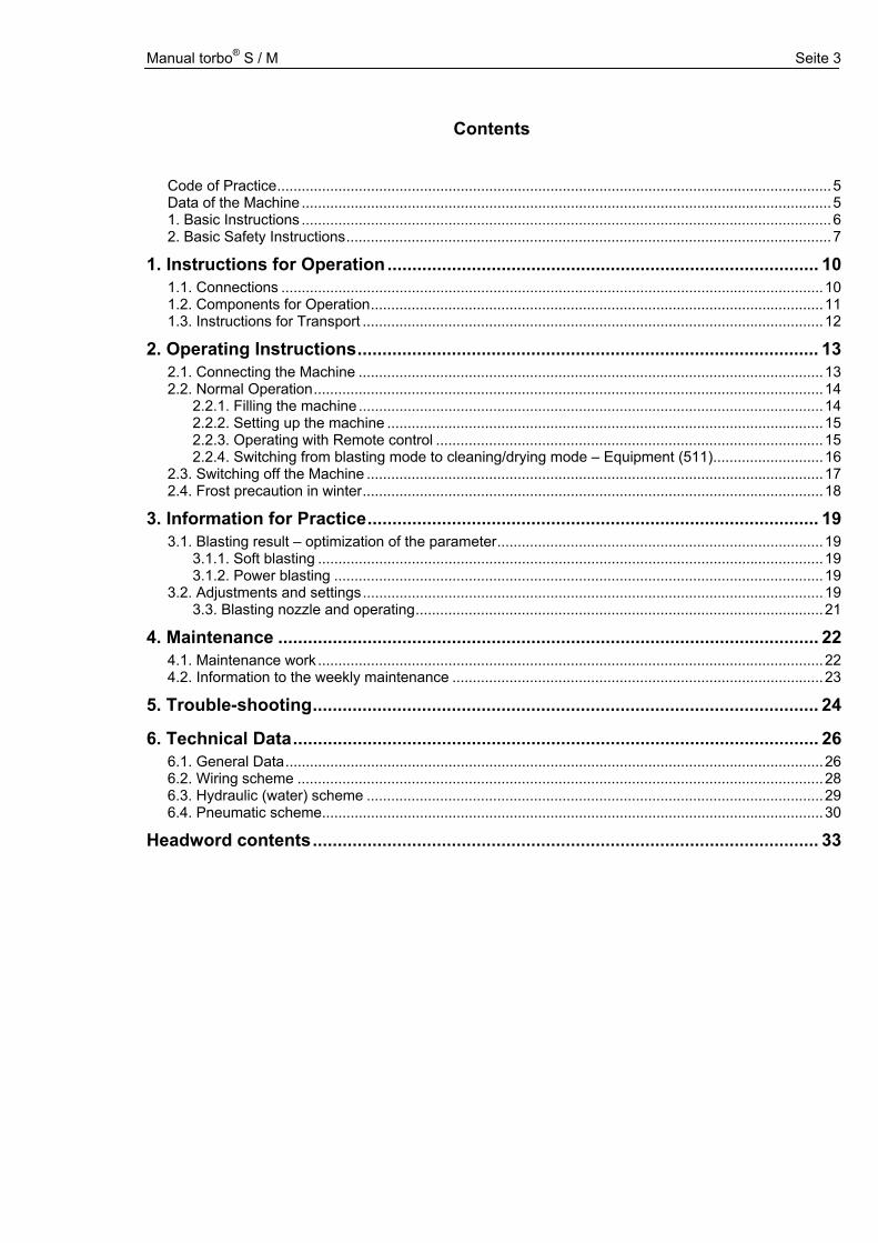
Contents
Code of Practice........................................................................................................................................5 Data of the Machine ..................................................................................................................................5 1. Basic Instructions ..................................................................................................................................6 2. Basic Safety Instructions.......................................................................................................................7
1. Instructions for Operation ....................................................................................... 10 1.1. Connections .....................................................................................................................................10 1.2. Components for Operation...............................................................................................................11 1.3. Instructions for Transport .................................................................................................................12
2. Operating Instructions............................................................................................. 13 2.1. Connecting the Machine ..................................................................................................................13 2.2. Normal Operation.............................................................................................................................14
2.2.1. Filling the machine ..................................................................................................................14 2.2.2. Setting up the machine ...........................................................................................................15 2.2.3. Operating with Remote control ...............................................................................................15 2.2.4. Switching from blasting mode to cleaning/drying mode – Equipment (511)...........................16
2.3. Switching off the Machine ................................................................................................................17 2.4. Frost precaution in winter.................................................................................................................18
3. Information for Practice........................................................................................... 19 3.1. Blasting result – optimization of the parameter................................................................................19
3.1.1. Soft blasting ............................................................................................................................19 3.1.2. Power blasting ........................................................................................................................19
3.2. Adjustments and settings.................................................................................................................19 3.3. Blasting nozzle and operating....................................................................................................21
4. Maintenance ............................................................................................................. 22 4.1. Maintenance work ............................................................................................................................22 4.2. Information to the weekly maintenance ...........................................................................................23
5. Trouble-shooting...................................................................................................... 24
6. Technical Data.......................................................................................................... 26 6.1. General Data....................................................................................................................................26 6.2. Wiring scheme .................................................................................................................................28 6.3. Hydraulic (water) scheme ................................................................................................................29 6.4. Pneumatic scheme...........................................................................................................................30
Headword contents...................................................................................................... 33

Manual torbo® S / M Seite 4
Manual torbo® S / M Seite 5
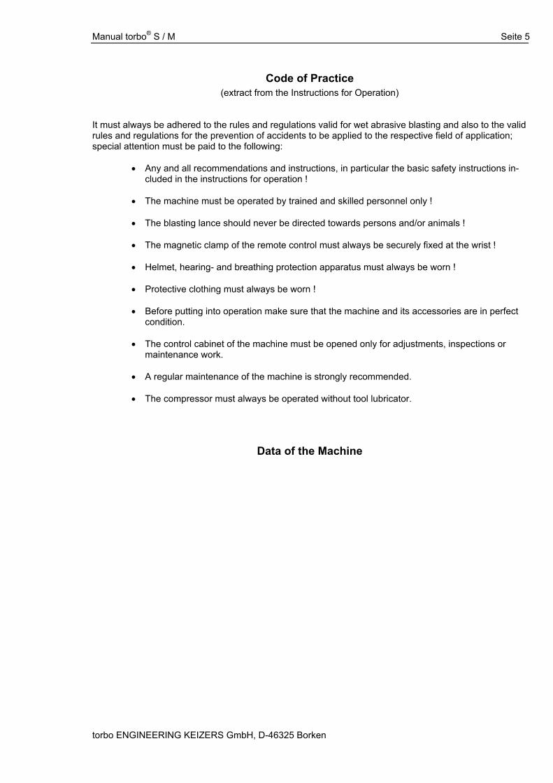
Code of Practice (extract from the Instructions for Operation)
It must always be adhered to the rules and regulations valid for wet abrasive blasting and also to the valid rules and regulations for the prevention of accidents to be applied to the respective field of application; special attention must be paid to the following: • Any and all recommendations and instructions, in particular the basic safety instructions in-
cluded in the instructions for operation !
• The machine must be operated by trained and skilled personnel only !
• The blasting lance should never be directed towards persons and/or animals !
• The magnetic clamp of the remote control must always be securely fixed at the wrist !
• Helmet, hearing- and breathing protection apparatus must always be worn !
• Protective clothing must always be worn !
• Before putting into operation make sure that the machine and its accessories are in perfect condition.
• The control cabinet of the machine must be opened only for adjustments, inspections or
maintenance work.
• A regular maintenance of the machine is strongly recommended.
• The compressor must always be operated without tool lubricator.
Data of the Machine torbo ENGINEERING KEIZERS GmbH, D-46325 Borken
Manual torbo® S / M - Basic Instructions Seite 6
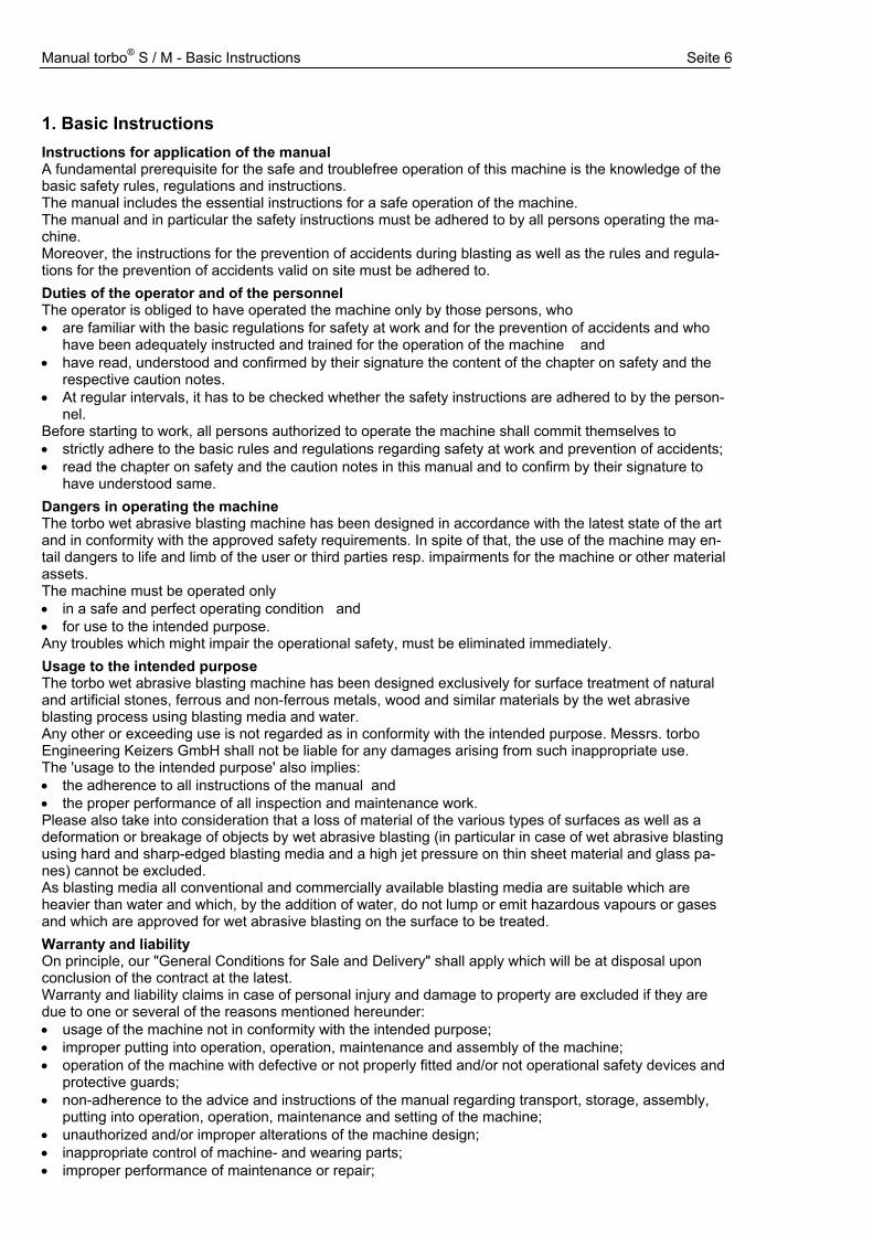
1. Basic Instructions Instructions for application of the manual A fundamental prerequisite for the safe and troublefree operation of this machine is the knowledge of the basic safety rules, regulations and instructions. The manual includes the essential instructions for a safe operation of the machine. The manual and in particular the safety instructions must be adhered to by all persons operating the ma-chine. Moreover, the instructions for the prevention of accidents during blasting as well as the rules and regula-tions for the prevention of accidents valid on site must be adhered to. Duties of the operator and of the personnel The operator is obliged to have operated the machine only by those persons, who • are familiar with the basic regulations for safety at work and for the prevention of accidents and who
have been adequately instructed and trained for the operation of the machine and • have read, understood and confirmed by their signature the content of the chapter on safety and the
respective caution notes. • At regular intervals, it has to be checked whether the safety instructions are adhered to by the person-
nel. Before starting to work, all persons authorized to operate the machine shall commit themselves to • strictly adhere to the basic rules and regulations regarding safety at work and prevention of accidents; • read the chapter on safety and the caution notes in this manual and to confirm by their signature to
have understood same. Dangers in operating the machine The torbo wet abrasive blasting machine has been designed in accordance with the latest state of the art and in conformity with the approved safety requirements. In spite of that, the use of the machine may en-tail dangers to life and limb of the user or third parties resp. impairments for the machine or other material assets. The machine must be operated only • in a safe and perfect operating condition and • for use to the intended purpose. Any troubles which might impair the operational safety, must be eliminated immediately. Usage to the intended purpose The torbo wet abrasive blasting machine has been designed exclusively for surface treatment of natural and artificial stones, ferrous and non-ferrous metals, wood and similar materials by the wet abrasive blasting process using blasting media and water. Any other or exceeding use is not regarded as in conformity with the intended purpose. Messrs. torbo Engineering Keizers GmbH shall not be liable for any damages arising from such inappropriate use. The 'usage to the intended purpose' also implies: • the adherence to all instructions of the manual and • the proper performance of all inspection and maintenance work. Please also take into consideration that a loss of material of the various types of surfaces as well as a deformation or breakage of objects by wet abrasive blasting (in particular in case of wet abrasive blasting using hard and sharp-edged blasting media and a high jet pressure on thin sheet material and glass pa-nes) cannot be excluded. As blasting media all conventional and commercially available blasting media are suitable which are heavier than water and which, by the addition of water, do not lump or emit hazardous vapours or gases and which are approved for wet abrasive blasting on the surface to be treated. Warranty and liability On principle, our "General Conditions for Sale and Delivery" shall apply which will be at disposal upon conclusion of the contract at the latest. Warranty and liability claims in case of personal injury and damage to property are excluded if they are due to one or several of the reasons mentioned hereunder: • usage of the machine not in conformity with the intended purpose; • improper putting into operation, operation, maintenance and assembly of the machine; • operation of the machine with defective or not properly fitted and/or not operational safety devices and
protective guards; • non-adherence to the advice and instructions of the manual regarding transport, storage, assembly,
putting into operation, operation, maintenance and setting of the machine; • unauthorized and/or improper alterations of the machine design; • inappropriate control of machine- and wearing parts; • improper performance of maintenance or repair;
Manual torbo® S / M - Basic Instructions Seite 7
• accidents by the influence of foreign matter or Force Majeure. Copyright The copyright regarding this manual remains with Messrs. torbo ENGINEERING KEIZERS GmbH, D-46325 Borken. This manual is intended exclusively for use by the operator and its personnel. It contains instructions and advice which - neither wholly nor partly - may be copied, divulged or otherwise disclosed. Any infringement may entail criminal prosecution.
2. Basic Safety Instructions Definition of symbols and references In this manual, the following symbols and definitions of dangers are used:
! Danger !
This symbol defines an imminent danger for life and health of persons. The non-adherence to these instructions will entail severe effects detrimental to health and even highly dangerous injuries.
!Warning
This symbol defines a possible danger for life and health of persons. The non-adherence to these instructions may entail severe effects detrimental to health and even highly dangerous injuries.
!Caution
This symbol defines a situation which might become dangerous. The non-adherence to these instructions may entail slight injuries or damages to property.
This symbol means essential instructions for a proper handling of the machine. The non-adherence to these instructions may entail troubles at the machine or in the environment.
This symbol refers to hints and recommendations for use and in particular to useful information. They will help you to make an optimal use of all functions of the machine.
Organizational measures The operator is obliged to place at disposal the required personal protective outfit (e.g. hearing- and breathing apparatus and face guards). The available protective and safety equipment must be checked at regular intervals. Safety devices be properly installed and operable. Protective devices, guards etc. may be removed only at standstill of the depressurized machine which has been secured against re-start. Informal safety measures The manual forms part of the machine and has always to be kept on site. Apart from the manual, the rules and regulations for the prevention of accidents during abrasive blasting as well as the locally valid rules and regulations for the prevention of accidents and for environmental protection must always be at disposal and adhered to. It must be ensured that the safety instructions and warning boards at the ma-chine are always legible. Training of the personnel The machine must be operated resp. put into operation only by trained and instructed personnel. Untrained personnel or personnel to be trained and instructed may operate the machine only under the supervision of experienced and skilled persons. The competence with regard to putting into operation, operating, maintenance, assembly, setting and re-pair must be clearly stipulated. Safety measures under normal service conditions In normal operation of the blasting machine, the following points must be observed: The machine must be put into operation only if:
all protective devices are fully operable, all connections have been made and secured, the magnetic clamp of the remote control has been fixed at the wrist of the operator and does not con-tact the remote control and, if the operator keeps a firm hold on the manual blasting nozzle/lance.
• Before switching on or starting the machine it must be made sure that nobody can be jeopardized he-reby.
• At least once per shift, the machine and its equipment must be checked for externally visible dam-ages.
Manual torbo® S / M - Basic Instructions Seite 8
!Danger !
• The blasting lance must never be directed to persons and/or animals ! • Never direct the blasting lance to objects which are not to be subject to surface treatment. • The inspection of the machine also includes its equipment.
Dangers due to electric energy • If works have to be performed at the electric supply system, this must be done by a skilled electrician
only. • The electric equipment of the machine must be checked at regular intervals. Loose connections and
scorched cables must be eliminated immediately. • The control cabinet must always be kept closed. Authorized personnel only shall have access to the
control cabinet using a key or adequate tool. • When working at live parts, a second person must assist who in case of need could actuate
the main switch. Dangers due to pneumatic energy • Pneumatic equipment must be operated only by personnel disposing of special knowledge and ex-
perience in the field of pneumatics. • Before tackling any repair work, sections of the pneumatic system and delivery conducts to be opened
must be depressurized. • At reasonable intervals, pneumatic hose pipes are to be exchanged even if no deficiencies impairing
the safety are visible. Special hazards When operating the machine, special attention has to be paid to the following in order to avoid hazards: • Never direct the blasting nozzle towards persons and/or animals ! • The blasting nozzle must not be directed towards objects which are not allowed to be blasted ! • Keep a tight hold on the blasting lance during start (back kick of the blasting lance!) • Unauthorized starting of the machine in case of interruptions (also short interruptions) must be avoi-
ded. • Machine to be made inaccessible for unauthorized people. Blasting nozzle and remote control to be
made inaccessible for unauthorized people. • During interruptions, magnetic clamp of the remote control to be put into jacket- or trouser pocket. • When operating the machine, the control cabinet must be kept closed and made inaccessible for un-
authorized people. Dangers due to superfines as well as noxious gases and vapours The concentration of fine dusts during operation of the machine is detrimental to health. The operators therefore have to be protected by an adequate protective outfit or protective measures against inhalation of superfines. The addition of chemical or other agents must be clarified with the producer and/or supplier of the agents. If on account of these agents or by using these agents in combination with water and/or blasting media health risks should arise, adequate protective measures must be taken. If by the use of these agents the functions of the machine should be impaired, a written confirmation must be obtained from torbo Engineering Keizers GmbH, D-46325 Borken, before using such agents.
!Warning
• Adequate breathing protection is to be ensured when working on the machine. • Adhere to the instructions of the producer when using other substances than water and/oder
commercially available blasting media.
Dangers due to the noise of the machine During the operation of the machine, the continuous sound intensity level depening on the setting a-mounts to 105 dB(A) which might be higher on account of unfavourable local conditions. The operating staff must be protected by an adequate outfit or protective measures against impairment of hearing.
!Warning
• Adequate hearing protection is to be ensured when working on the machine.
Manual torbo® S / M - Basic Instructions Seite 9
Maintenance, repair, trouble-shooting Regarding maintenance, repair and trouble-shooting the following requirements must be fulfilled: • The specified maintenance and inspection work must be carried through according to schedule. • The operating staff must be informed in time of any intended maintenance and/or repair. • All plants, systems, machines, appliances upstream and downstream of the wet abrasive blasting ma-
chine, as well as all supply systems like current, compressed air and pressurized water are to be se-cured against accidental actuation.
• For all maintenance-, inspection- and repair works, the machine must be de-energized and depressur-ized and secured against re-start, attach warning board to prevent from restarting the machine; uncouple compressed-air- and pressurized-water hoses from the machine; disconnect cable from power source.
• After completion of the works check loosened screws and connections for tight fitting. • After completion of the works check all safety devices for correct functioning. Alterations of the machine design No alterations, attachments or conversions of the machine are allowed without the approval of the manu-facturer. All conversion measures are subject to the written approval of Messrs. torbo Engineering Keizers GmbH, D-46325 Borken. Any machine parts which are not in a perfect state and condition, must be exchanged immediately. Only original spare- and wear parts are to be used as in case of parts bought elsewhere it cannot be war-ranted that they have been designed and manufactured to fulfil the requirements regarding quality and safety. Disposal of substances/materials and cleaning of machine All substances and materials used have to be properly handled and disposed of. In particular, this applies to: • Blasting media and water used in the performance of any works and jobs, • Additives used, like e.g. rust retarding agents, solvents for cleaning the machine etc.
Manual torbo® S / M - Instructions for Operation Seite 10
1. Instructions for Operation
1.1. Connections
!Warning
• The technical data and requirements to be fulfilled by compressed-air hoses may be taken from the technical specification (look at chapter 4);
• Hoses and cable are to be checked for wear and damage and exchanged, if necessary;
• Couplings of compressed-air hoses must always be secured against loosening.
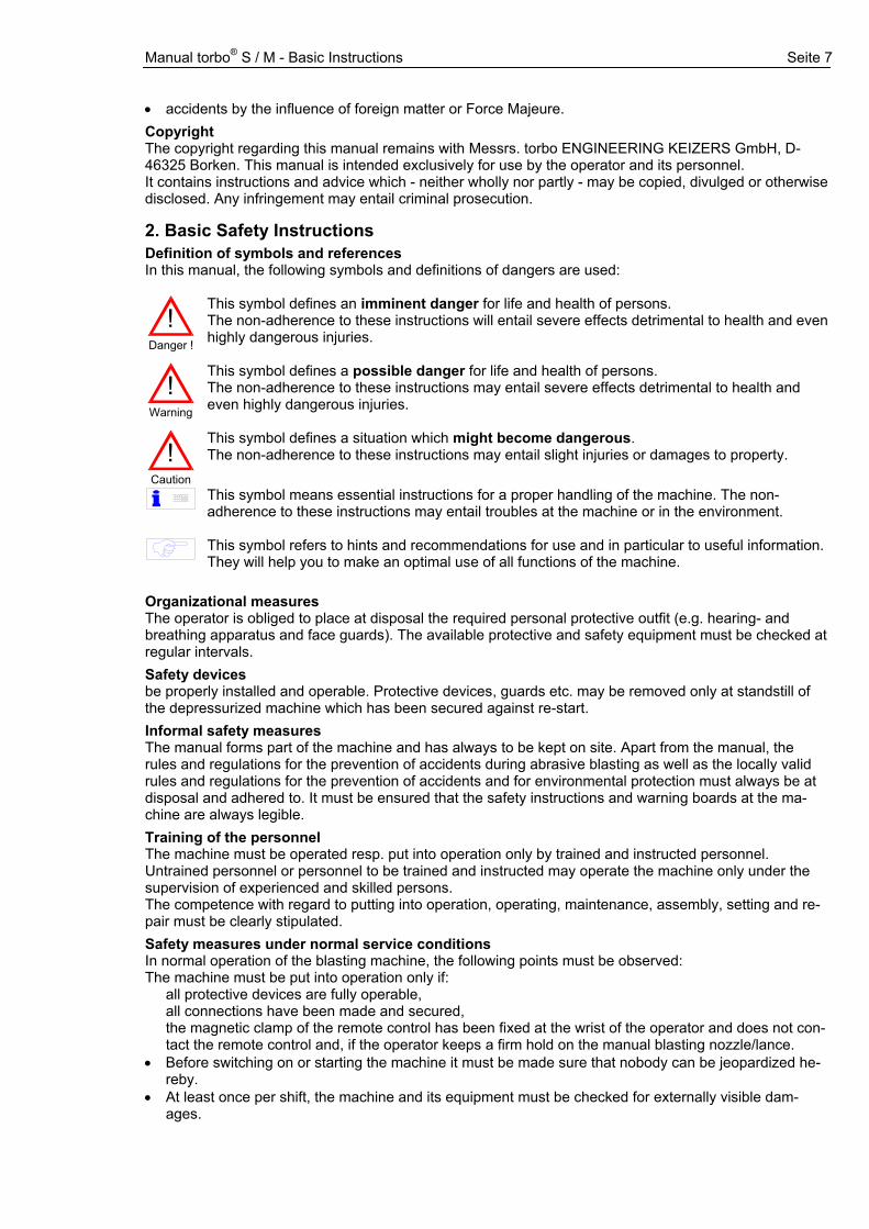
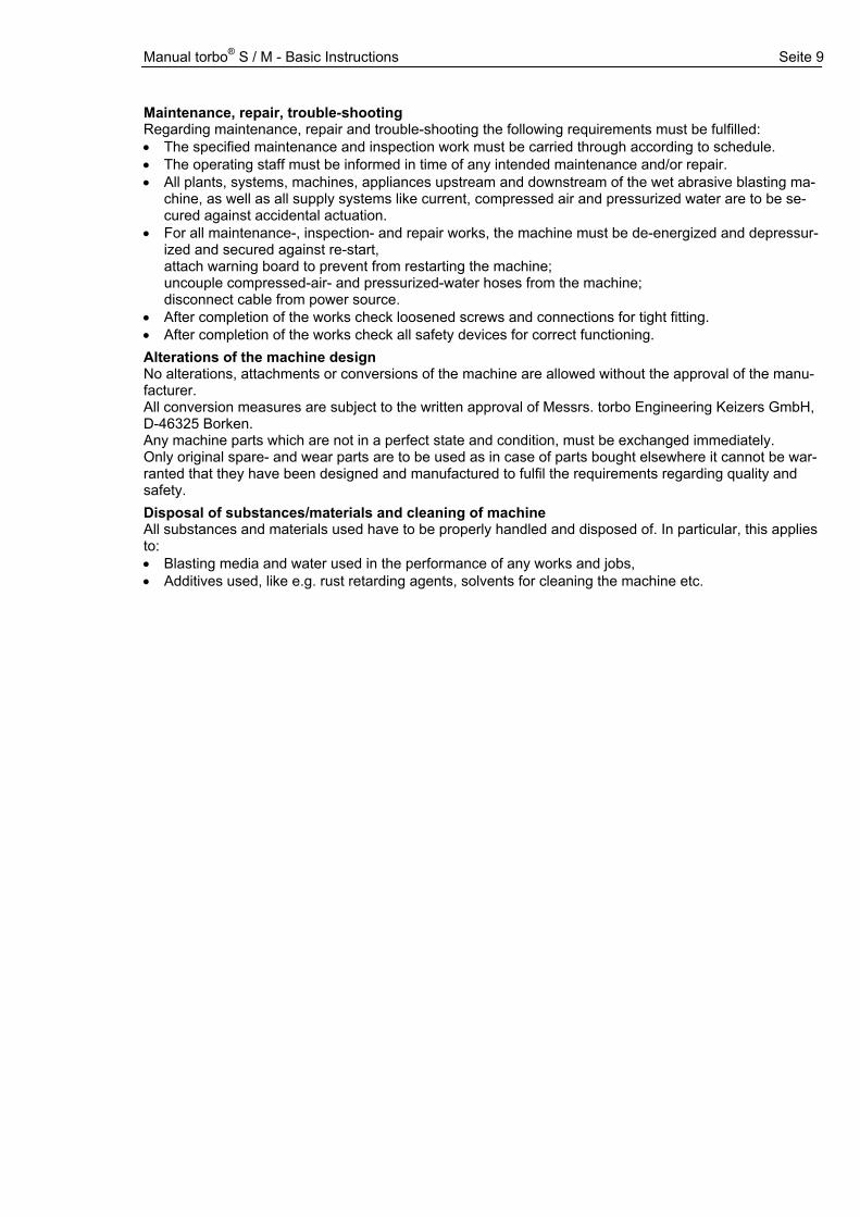
Water supply (E): Make sure that the machine is connected to a correct water supply (example water tank); connect upto 12 bar.
• Use only clean water and clean-up the water filter weekly, it will increase the service life of the pump.
Overflow port (22): This overflow has been designed to dis-charge excessive water when filling the machine, and after ter-mination of the blasting, to relieve the pressure vessel from the hydraulic pressure.
• Use the torbo water tank 98 to re-use the water.
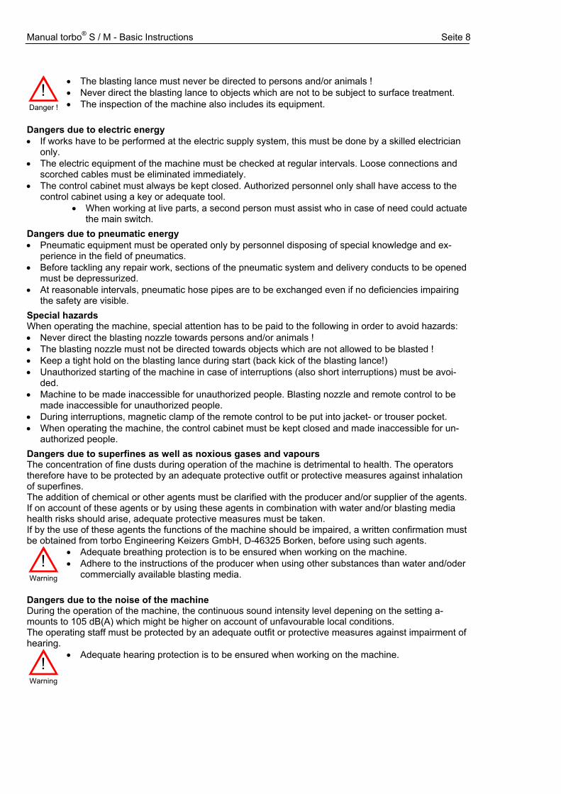
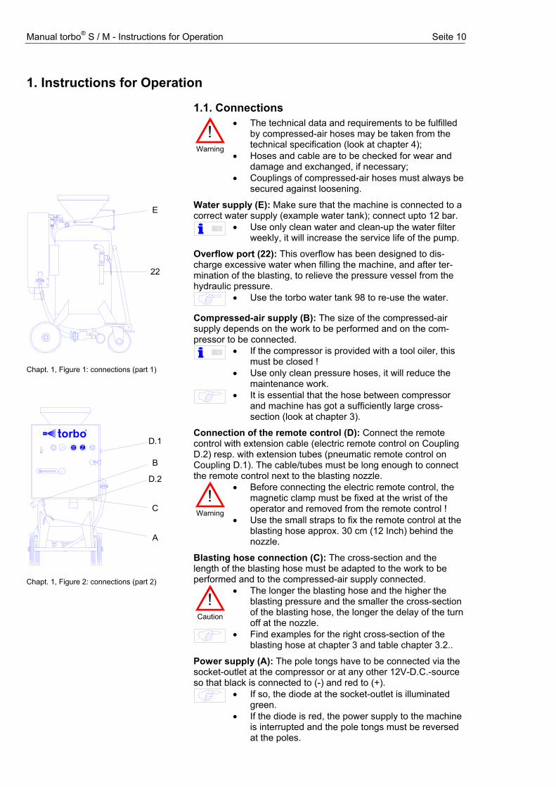
Compressed-air supply (B): The size of the compressed-air supply depends on the work to be performed and on the com-pressor to be connected.
• If the compressor is provided with a tool oiler, this must be closed !
• Use only clean pressure hoses, it will reduce the maintenance work.
• It is essential that the hose between compressor and machine has got a sufficiently large cross-section (look at chapter 3).
Connection of the remote control (D): Connect the remote control with extension cable (electric remote control on Coupling D.2) resp. with extension tubes (pneumatic remote control on Coupling D.1). The cable/tubes must be long enough to connect the remote control next to the blasting nozzle.
!Warning
• Before connecting the electric remote control, the magnetic clamp must be fixed at the wrist of the operator and removed from the remote control !
• Use the small straps to fix the remote control at the blasting hose approx. 30 cm (12 Inch) behind the nozzle.
Blasting hose connection (C): The cross-section and the length of the blasting hose must be adapted to the work to be performed and to the compressed-air supply connected.
!Caution
• The longer the blasting hose and the higher the blasting pressure and the smaller the cross-section of the blasting hose, the longer the delay of the turn off at the nozzle.
• Find examples for the right cross-section of the blasting hose at chapter 3 and table chapter 3.2..
Power supply (A): The pole tongs have to be connected via the socket-outlet at the compressor or at any other 12V-D.C.-source so that black is connected to (-) and red to (+).
E
22
Chapt. 1, Figure 1: connections (part 1)
B
D.2
C
A
0 , 6
45
D
6 2
1
3S
0
34
6
5 1
0 ,6
2Z
to orb R
D.1
Chapt. 1, Figure 2: connections (part 2)
• If so, the diode at the socket-outlet is illuminated green.
• If the diode is red, the power supply to the machine is interrupted and the pole tongs must be reversed at the poles.
Manual torbo® S / M - Instructions for Operation Seite 11
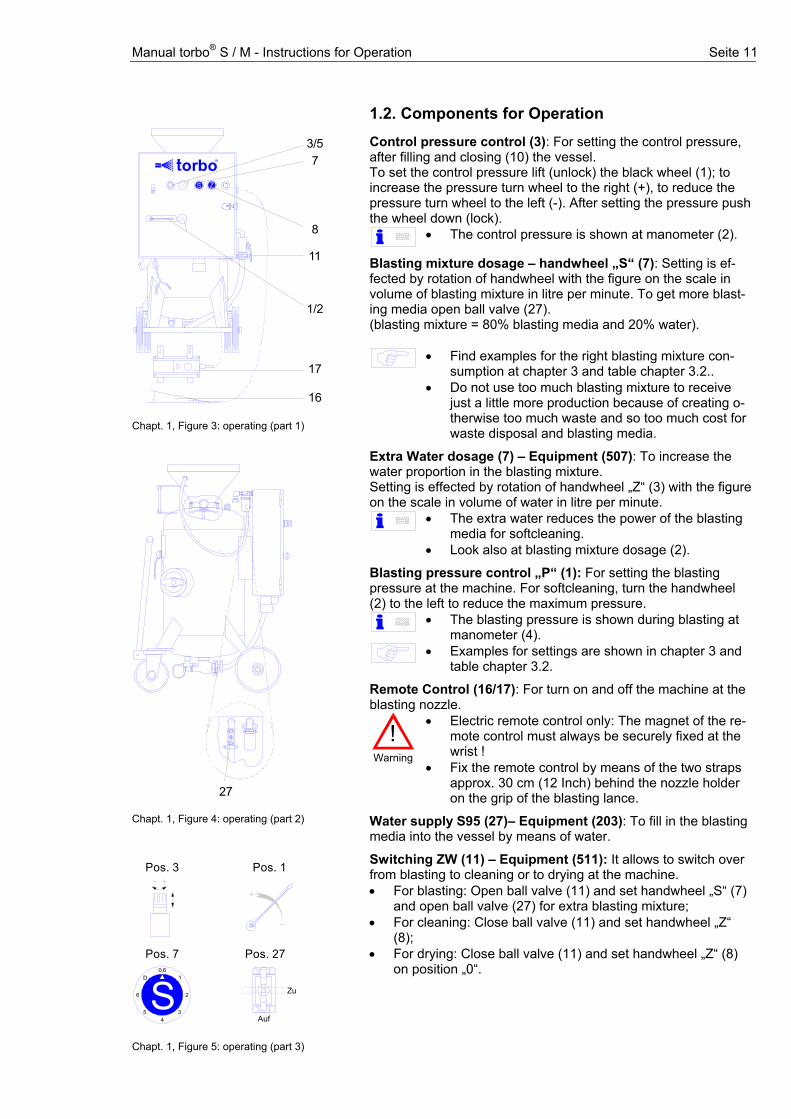
1.2. Components for Operation
Control pressure control (3): For setting the control pressure, after filling and closing (10) the vessel. To set the control pressure lift (unlock) the black wheel (1); to increase the pressure turn wheel to the right (+), to reduce the pressure turn wheel to the left (-). After setting the pressure push the wheel down (lock).
• The control pressure is shown at manometer (2).
Blasting mixture dosage – handwheel „S“ (7): Setting is ef-fected by rotation of handwheel with the figure on the scale in volume of blasting mixture in litre per minute. To get more bing media open ball valve (27).
last-
(blasting mixture = 80% blasting media and 20% water).
• Find examples for the right blasting mixture con-sumption at chapter 3 and table chapter 3.2..
• Do not use too much blasting mixture to receive just a little more production because of creating o-therwise too much waste and so too much cost for waste disposal and blasting media.
Extra Water dosage (7) – Equipment (507): To increase the water proportion in the blasting mixture. Setting is effected by rotation of handwheel „Z“ (3) with the figure on the scale in volume of water in litre per minute.
• The extra water reduces the power of the blasting media for softcleaning.
• Look also at blasting mixture dosage (2).
Blasting pressure control „P“ (1): For setting the blasting pressure at the machine. For softcleaning, turn the handwheel (2) to the left to reduce the maximum pressure.
• The blasting pressure is shown during blasting at manometer (4).
• Examples for settings are shown in chapter 3 and table chapter 3.2.
Remote Control (16/17): For turn on and off the machine at the blasting nozzle.
!Warning
• Electric remote control only: The magnet of the re-mote control must always be securely fixed at the wrist !
• Fix the remote control by means of the two straps approx. 30 cm (12 Inch) behind the nozzle holder on the grip of the blasting lance.
Water supply S95 (27)– Equipment (203): To fill in the blasting media into the vessel by means of water.
3/57
8
0 , 6
45
D
6 2
1
3S
0
34
6
5 1
0 ,6
2Z
to orb R
1/2
16
17
11
Chapt. 1, Figure 3: operating (part 1)
27 Chapt. 1, Figure 4: operating (part 2)
Pos. 3
Pos. 70,6
45
D
6 2
1
3S
Pos. 1
Pos. 27
Auf
Zu
Chapt. 1, Figure 5: operating (part 3)
Switching ZW (11) – Equipment (511): It allows to switch over from blasting to cleaning or to drying at the machine. • For blasting: Open ball valve (11) and set handwheel „S“ (7)
and open ball valve (27) for extra blasting mixture; • For cleaning: Close ball valve (11) and set handwheel „Z“
(8); • For drying: Close ball valve (11) and set handwheel „Z“ (8)
on position „0“.
Manual torbo® S / M - Instructions for Operation Seite 12
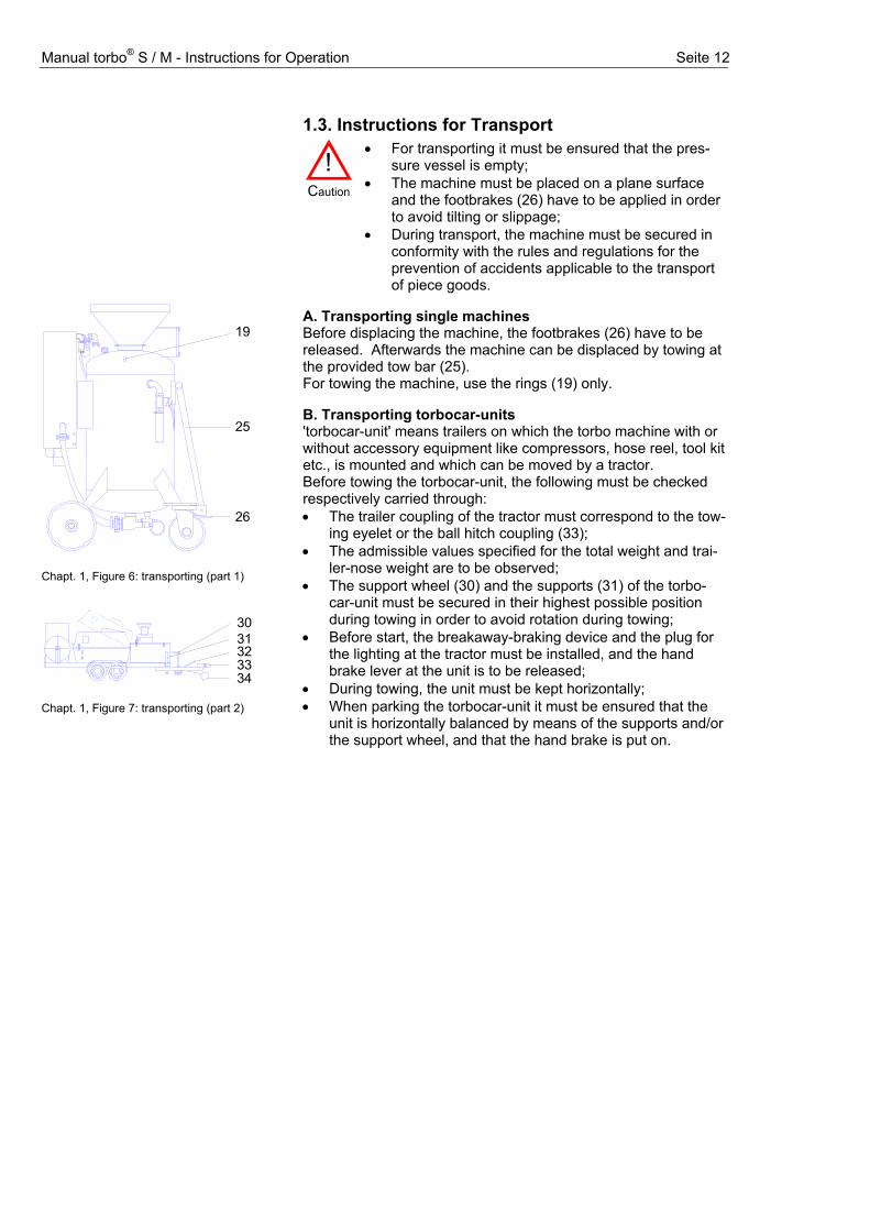
1.3. Instructions for Transport
!
Caution
• For transporting it must be ensured that the pres-sure vessel is empty;
• The machine must be placed on a plane surface and the footbrakes (26) have to be applied in order to avoid tilting or slippage;
• During transport, the machine must be secured in conformity with the rules and regulations for the prevention of accidents applicable to the transport of piece goods.
A. Transporting single machines Before displacing the machine, the footbrakes (26) have to be released. Afterwards the machine can be displaced by towing at the provided tow bar (25). For towing the machine, use the rings (19) only.
B. Transporting torbocar-units 'torbocar-unit' means trailers on which the torbo machine with or without accessory equipment like compressors, hose reel, tool kit etc., is mounted and which can be moved by a tractor. Before towing the torbocar-unit, the following must be checked respectively carried through:
19
25
26
Chapt. 1, Figure 6: transporting (part 1)
3031323334
Chapt. 1, Figure 7: transporting (part 2)
• The trailer coupling of the tractor must correspond to the tow-ing eyelet or the ball hitch coupling (33);
• The admissible values specified for the total weight and trai-ler-nose weight are to be observed;
• The support wheel (30) and the supports (31) of the torbo-car-unit must be secured in their highest possible position during towing in order to avoid rotation during towing;
• Before start, the breakaway-braking device and the plug for the lighting at the tractor must be installed, and the hand brake lever at the unit is to be released;
• During towing, the unit must be kept horizontally; • When parking the torbocar-unit it must be ensured that the
unit is horizontally balanced by means of the supports and/or the support wheel, and that the hand brake is put on.
Manual torbo® S / M - Instructions for Operation Seite 13
2. Operating Instructions
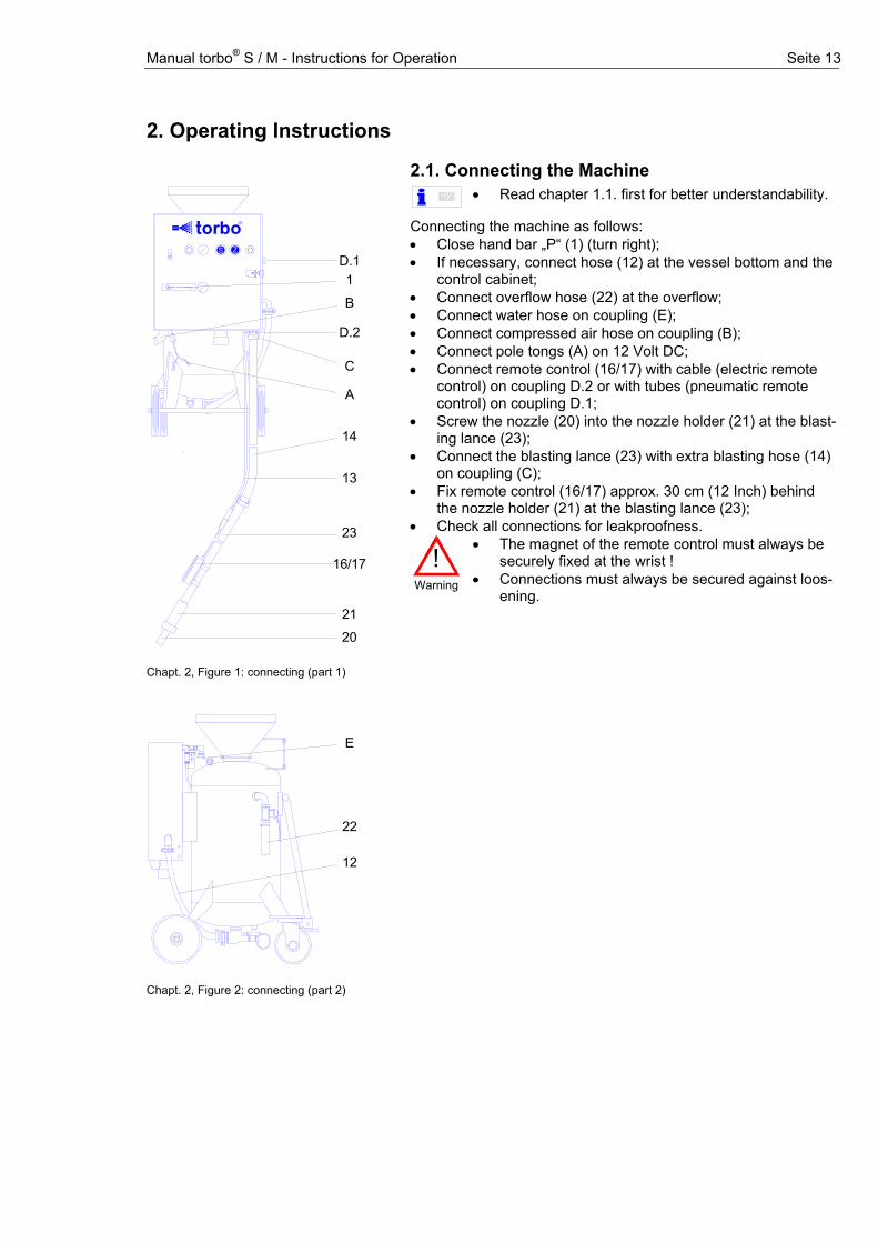
2.1. Connecting the Machine • Read chapter 1.1. first for better understandability.
Connecting the machine as follows: • Close hand bar „P“ (1) (turn right); • If necessary, connect hose (12) at the vessel bottom and the
control cabinet; • Connect overflow hose (22) at the overflow; • Connect water hose on coupling (E); • Connect compressed air hose on coupling (B); • Connect pole tongs (A) on 12 Volt DC; • Connect remote control (16/17) with cable (electric remote
control) on coupling D.2 or with tubes (pneumatic remote control) on coupling D.1;
• Screw the nozzle (20) into the nozzle holder (21) at the blast-ing lance (23);
• Connect the blasting lance (23) with extra blasting hose (14) on coupling (C);
• Fix remote control (16/17) approx. 30 cm (12 Inch) behind the nozzle holder (21) at the blasting lance (23);
• Check all connections for leakproofness.
1
B
D.2
0 , 6
45
D
6 2
1
3S
0
34
6
5 1
0 ,6
2Z
to orb R
C
A
14
13
23
16/17
21
20
D.1
Chapt. 2, Figure 1: connecting (part 1)
E
22
12
Chapt. 2, Figure 2: connecting (part 2)
!Warning
• The magnet of the remote control must always be securely fixed at the wrist !
• Connections must always be secured against loos-ening.
Manual torbo® S / M - Instructions for Operation Seite 14
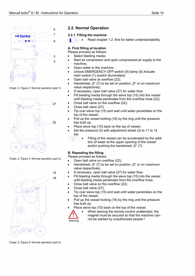
2.2. Normal Operation 2.2.1. Filling the machine
• Read chapter 1.2. first for better understandability.
A. First filling at location Please proceed as follows: • Select blasting media; • Start air compressor and open compressed-air supply to the
machine; • Open water to the machine; • Unlock EMERGENCY-OFF-switch (9) (lamp (6) Actuate
main switch (1) (switch illuminated); • Open ball valve at overflow (22); • Handwheel „S“ (7) to be set on position „D“ or on maximum
value respectively; • If necessary, open ball valve (27) for water flow; • Fill blasting media through the sieve top (15) into the vessel
until blasting media penetrates from the overflow hose (22); • Close ball valve on the overflow (22); • Close ball valve (27); • Tip over sieve top (15) and wait until water penetrates on the
top of the vessel; • Pull up the vessel locking (18) by the ring until the pressure
has built up; • Place sieve top (15) back on the top of vessel; • Set the pressure (5) with adjustment wheel (3) to 11 to 12
bar.
• Filling of the vessel can be accelerated by the addi-tion of water at the upper opening of the vessel and/or pushing the handwheel „S“ (7).
B. Repeating the filling Please proceed as follows: • Open ball valve on overflow (22); • Handwheel „S“ (7) to be set on position „D“ or on maximum
value respectively; • If necessary, open ball valve (27) for water flow; • Fill blasting media through the sieve top (15) into the vessel
until blasting media penetrates from the overflow hose; • Close ball valve on the overflow (22); • Close ball valve (27); • Tip over sieve top (15) and wait until water penetrates on the
top of the vessel; • Pull up the vessel locking (18) by the ring until the pressure
has built up; • Place sieve top (15) back on the top of the vessel.
67
5
3
90 , 6
45
D
6 2
1
3S
0
34
6
5 1
0 ,6
2Z
to orb R
Chapt. 2, Figure 3: Normal operation (part 1)
22
27
Chapt. 2, Figure 4: Normal operation (part 2)
15
18
Chapt. 2, Figure 5: Normal operation (part 3)
!
Warning
• When leaving the remote control unattended, the magnet must be secured so that the machine can-not be started by unauthorized people !

Manual torbo® S / M - Instructions for Operation Seite 15
2.2.2. Setting up the machine When the machine is connected, the vessel is closed respec-tively the vessel pressure is adjusted, the machine has to be ad-justed to the application; please proceed as follows: • Set blasting media at handwheel „S“ (7); • Set extra water at handwheel „Z“ (8), to increase the water-
proportion in the blasting mixture (for soft cleaning); • Set the blasting pressure (2) at ball valve (1) (only possible
during operation). • To get more information about the correct setting to
the respective application see chapter „3. Informa-tion for Practice“.
• If necessary, connect more blasting hose and ex-tension cable and control and re-set the blasting pressure again.
!
Warning
• When more than 20 m (60 ft.) blasting hose are connected, check if the past-flow time is more than 1 secund. If so, additionally the switch-off device QE99 has to be installed approx. 10 to 20 m (30 to 60 ft.) behind the blasting nozzle to reduce the past-flow time to less than 1 second.
7
2
1
80 , 6
45
D
6 2
1
3S
0
34
6
5 1
0 ,6
2Z
to orb R
chapt. 2, Figute 6: Setting up the machine
2.2.3. Operating with electric Remote control • Read chapter 2.1. and 2.2.1. first for better under-
standability. • Put magnet (17.4) on position (17.1) at the remote control
(diode (17.2) illuminated); • To start/blasting: Actuate push-button (17.3) at the remote
control (diode (17.2) goes out); • To switch off: Remove magnet (17.4) from remote control. Each removing of the magnet stops blasting. To restart with blasting, put the magnet on position at the remote control and actuate push-button.
!
Warning
• Any and all recommendations and instructions, in particular the basic safety instructions, must be paid attention to !
• The blasting lance should never be directed to-wards persons and/or animals !
• The higher the blasting pressure is, the higher is the recoil at the nozzle.
• The longer the blasting hose is, the longer is the shut down time at the nozzle.
17.3
17.117.417.2
Chapt. 2, Figure 7: Operating with Remote control FB S99
• Before starting read chapter 3. to find the right set-ting.
• If necessary, connect more blasting hose and ex-tension cable and control the blasting pressure a-gain.
Manual torbo® S / M - Instructions for Operation Seite 16
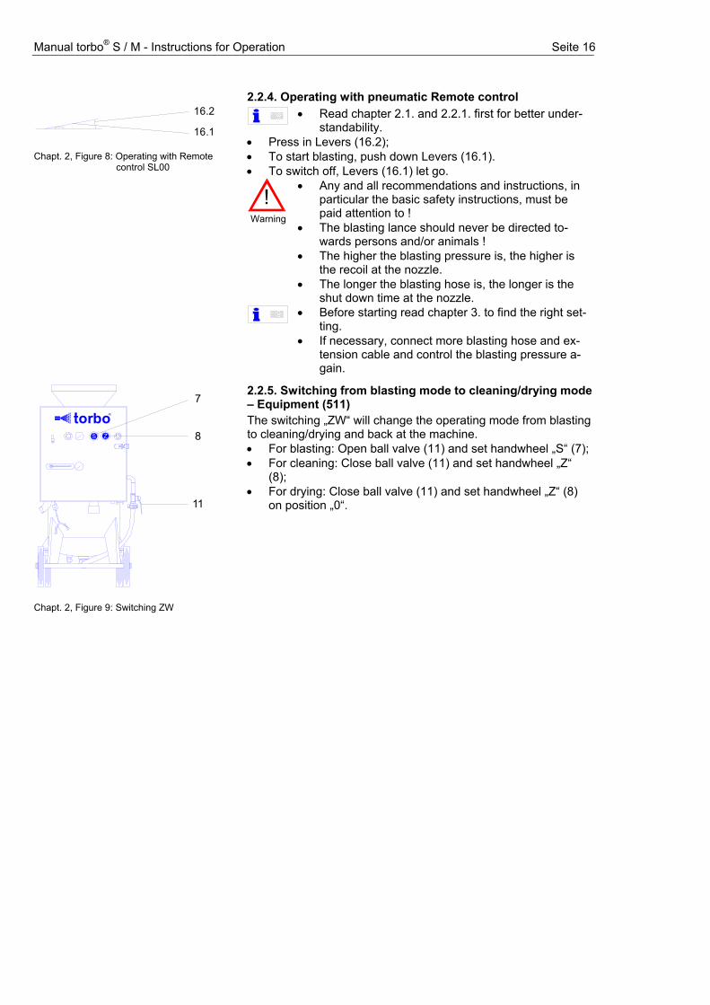
2.2.4. Operating with pneumatic Remote control
• Read chapter 2.1. and 2.2.1. first for better under-standability.
• Press in Levers (16.2); • To start blasting, push down Levers (16.1). • To switch off, Levers (16.1) let go.
!
Warning
• Any and all recommendations and instructions, in particular the basic safety instructions, must be paid attention to !
• The blasting lance should never be directed to-wards persons and/or animals !
• The higher the blasting pressure is, the higher is the recoil at the nozzle.
• The longer the blasting hose is, the longer is the shut down time at the nozzle.
16.2
16.1 Chapt. 2, Figure 8: Operating with Remote control SL00
• Before starting read chapter 3. to find the right set-ting.
• If necessary, connect more blasting hose and ex-tension cable and control the blasting pressure a-gain.
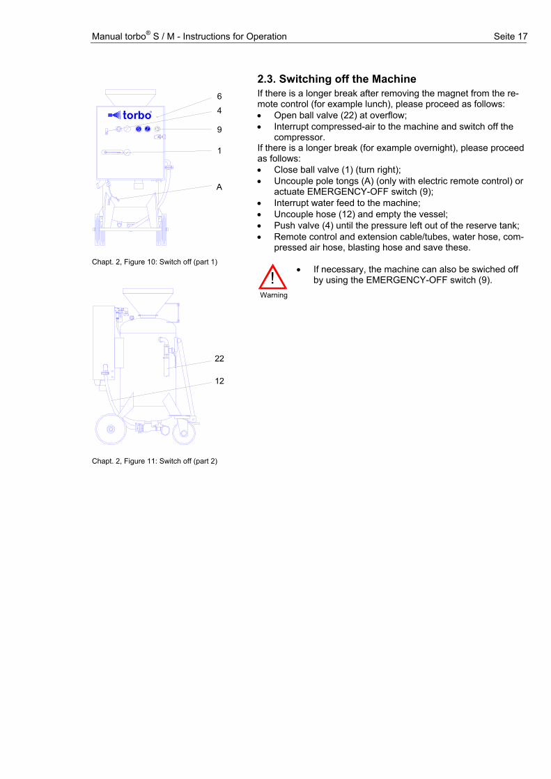
2.2.5. Switching from blasting mode to cleaning/drying mode – Equipment (511) The switching „ZW“ will change the operating mode from blasting to cleaning/drying and back at the machine.
7
80 , 6
45
D
6 2
1
3S
0
34
6
5 1
0 ,6
2Z
to orb R
11
Chapt. 2, Figure 9: Switching ZW
• For blasting: Open ball valve (11) and set handwheel „S“ (7); • For cleaning: Close ball valve (11) and set handwheel „Z“
(8); • For drying: Close ball valve (11) and set handwheel „Z“ (8)
on position „0“.
Manual torbo® S / M - Instructions for Operation Seite 17
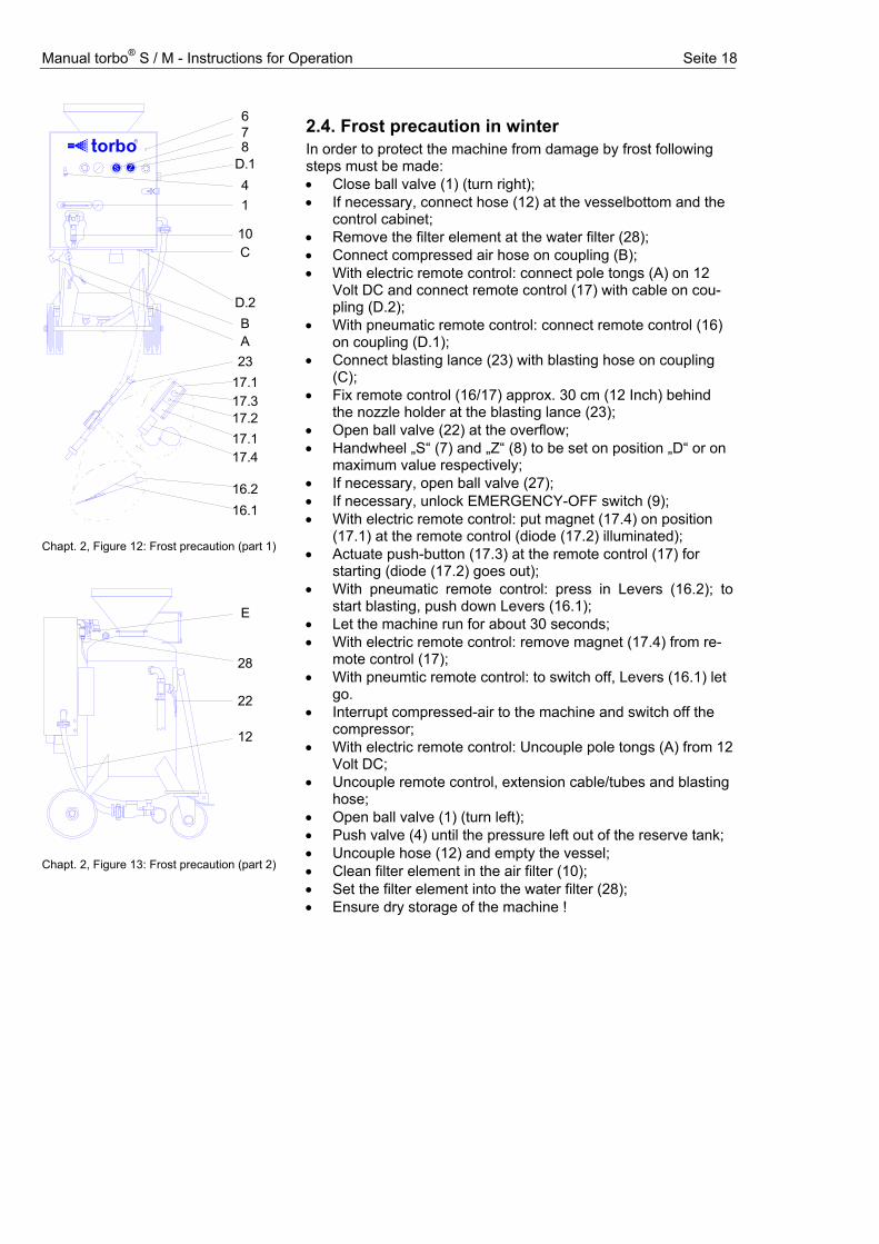
2.3. Switching off the Machine If there is a longer break after removing the magnet from the re-mote control (for example lunch), please proceed as follows: • Open ball valve (22) at overflow; • Interrupt compressed-air to the machine and switch off the
compressor. If there is a longer break (for example overnight), please proceed as follows: • Close ball valve (1) (turn right); • Uncouple pole tongs (A) (only with electric remote control) or
actuate EMERGENCY-OFF switch (9); • Interrupt water feed to the machine; • Uncouple hose (12) and empty the vessel; • Push valve (4) until the pressure left out of the reserve tank; • Remote control and extension cable/tubes, water hose, com-
pressed air hose, blasting hose and save these.
64
1
A
90 , 6
45
D
6 2
1
3S
0
34
6
5 1
0 ,6
2Z
to orb R
Chapt. 2, Figure 10: Switch off (part 1)
22
12
Chapt. 2, Figure 11: Switch off (part 2)
!
Warning
• If necessary, the machine can also be swiched off by using the EMERGENCY-OFF switch (9).
Manual torbo® S / M - Instructions for Operation Seite 18
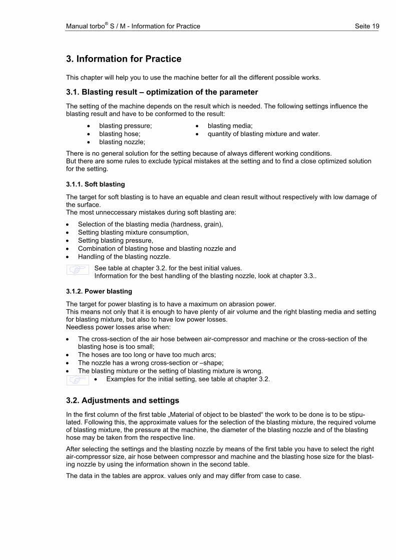
2.4. Frost precaution in winter In order to protect the machine from damage by frost following steps must be made:
678
41
10C
D.2BA23
17.117.317.2
17.417.1
0 , 6
45
D
6 2
1
3S
0
34
6
5 1
0 ,6
2Z
to orb R
D.1
16.216.1
Chapt. 2, Figure 12: Frost precaution (part 1)
22
E
12
28
Chapt. 2, Figure 13: Frost precaution (part 2)
• Close ball valve (1) (turn right); • If necessary, connect hose (12) at the vesselbottom and the
control cabinet; • Remove the filter element at the water filter (28); • Connect compressed air hose on coupling (B); • With electric remote control: connect pole tongs (A) on 12
Volt DC and connect remote control (17) with cable on cou-pling (D.2);
• With pneumatic remote control: connect remote control (16) on coupling (D.1);
• Connect blasting lance (23) with blasting hose on coupling (C);
• Fix remote control (16/17) approx. 30 cm (12 Inch) behind the nozzle holder at the blasting lance (23);
• Open ball valve (22) at the overflow; • Handwheel „S“ (7) and „Z“ (8) to be set on position „D“ or on
maximum value respectively; • If necessary, open ball valve (27); • If necessary, unlock EMERGENCY-OFF switch (9); • With electric remote control: put magnet (17.4) on position
(17.1) at the remote control (diode (17.2) illuminated); • Actuate push-button (17.3) at the remote control (17) for
starting (diode (17.2) goes out); • With pneumatic remote control: press in Levers (16.2); to
start blasting, push down Levers (16.1); • Let the machine run for about 30 seconds; • With electric remote control: remove magnet (17.4) from re-
mote control (17); • With pneumtic remote control: to switch off, Levers (16.1) let
go. • Interrupt compressed-air to the machine and switch off the
compressor; • With electric remote control: Uncouple pole tongs (A) from 12
Volt DC; • Uncouple remote control, extension cable/tubes and blasting
hose; • Open ball valve (1) (turn left); • Push valve (4) until the pressure left out of the reserve tank; • Uncouple hose (12) and empty the vessel; • Clean filter element in the air filter (10); • Set the filter element into the water filter (28); • Ensure dry storage of the machine !
Manual torbo® S / M - Information for Practice Seite 19
3. Information for Practice This chapter will help you to use the machine better for all the different possible works.
3.1. Blasting result – optimization of the parameter
The setting of the machine depends on the result which is needed. The following settings influence the blasting result and have to be conformed to the result:
• blasting pressure; • blasting hose; • blasting nozzle;
• blasting media; • quantity of blasting mixture and water.
There is no general solution for the setting because of always different working conditions. But there are some rules to exclude typical mistakes at the setting and to find a close optimized solution for the setting.
3.1.1. Soft blasting
The target for soft blasting is to have an equable and clean result without respectively with low damage of the surface. The most unneccessary mistakes during soft blasting are:
• Selection of the blasting media (hardness, grain), • Setting blasting mixture consumption, • Setting blasting pressure, • Combination of blasting hose and blasting nozzle and • Handling of the blasting nozzle.
See table at chapter 3.2. for the best initial values. Information for the best handling of the blasting nozzle, look at chapter 3.3..
3.1.2. Power blasting
The target for power blasting is to have a maximum on abrasion power. This means not only that it is enough to have plenty of air volume and the right blasting media and setting for blasting mixture, but also to have low power losses. Needless power losses arise when:
• The cross-section of the air hose between air-compressor and machine or the cross-section of the blasting hose is too small;
• The hoses are too long or have too much arcs; • The nozzle has a wrong cross-section or –shape; • The blasting mixture or the setting of blasting mixture is wrong.
• Examples for the initial setting, see table at chapter 3.2.
3.2. Adjustments and settings
In the first column of the first table „Material of object to be blasted“ the work to be done is to be stipu-lated. Following this, the approximate values for the selection of the blasting mixture, the required volume of blasting mixture, the pressure at the machine, the diameter of the blasting nozzle and of the blasting hose may be taken from the respective line.
After selecting the settings and the blasting nozzle by means of the first table you have to select the right air-compressor size, air hose between compressor and machine and the blasting hose size for the blast-ing nozzle by using the information shown in the second table.
The data in the tables are approx. values only and may differ from case to case.
Manual torbo® S / M - Information for Practice Seite 20
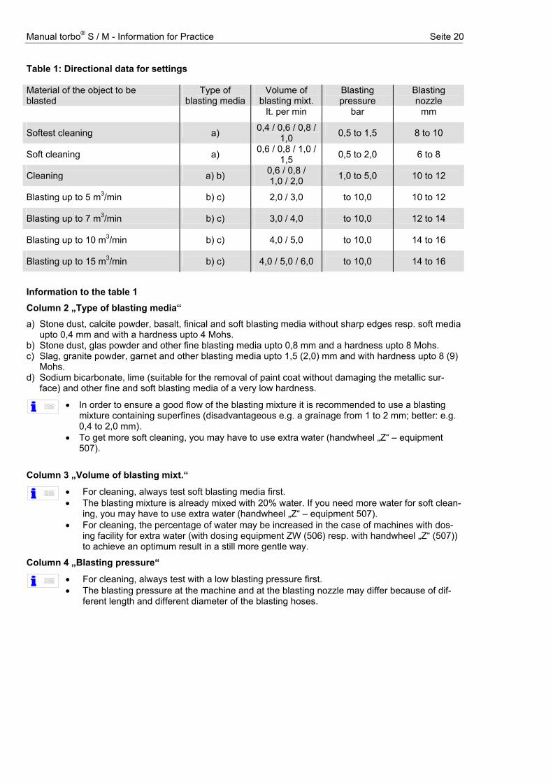
Table 1: Directional data for settings Material of the object to be blasted
Type of blasting media
Volume of blasting mixt.
Blasting pressure
Blasting nozzle
lt. per min bar mm
Softest cleaning
a) 0,4 / 0,6 / 0,8 / 1,0
0,5 to 1,5
8 to 10
Soft cleaning
a) 0,6 / 0,8 / 1,0 / 1,5
0,5 to 2,0
6 to 8
Cleaning
a) b) 0,6 / 0,8 / 1,0 / 2,0
1,0 to 5,0
10 to 12
Blasting up to 5 m3/min
b) c)
2,0 / 3,0
to 10,0
10 to 12
Blasting up to 7 m3/min
b) c)
3,0 / 4,0
to 10,0
12 to 14
Blasting up to 10 m3/min
b) c)
4,0 / 5,0
to 10,0
14 to 16
Blasting up to 15 m3/min
b) c)
4,0 / 5,0 / 6,0
to 10,0
14 to 16
Information to the table 1
Column 2 „Type of blasting media“
a) Stone dust, calcite powder, basalt, finical and soft blasting media without sharp edges resp. soft media upto 0,4 mm and with a hardness upto 4 Mohs.
b) Stone dust, glas powder and other fine blasting media upto 0,8 mm and a hardness upto 8 Mohs. c) Slag, granite powder, garnet and other blasting media upto 1,5 (2,0) mm and with hardness upto 8 (9)
Mohs. d) Sodium bicarbonate, lime (suitable for the removal of paint coat without damaging the metallic sur-
face) and other fine and soft blasting media of a very low hardness.
• In order to ensure a good flow of the blasting mixture it is recommended to use a blasting
mixture containing superfines (disadvantageous e.g. a grainage from 1 to 2 mm; better: e.g. 0,4 to 2,0 mm).
• To get more soft cleaning, you may have to use extra water (handwheel „Z“ – equipment 507).
Column 3 „Volume of blasting mixt.“
• For cleaning, always test soft blasting media first. • The blasting mixture is already mixed with 20% water. If you need more water for soft clean-
ing, you may have to use extra water (handwheel „Z“ – equipment 507). • For cleaning, the percentage of water may be increased in the case of machines with dos-
ing facility for extra water (with dosing equipment ZW (506) resp. with handwheel „Z“ (507)) to achieve an optimum result in a still more gentle way.
Column 4 „Blasting pressure“
• For cleaning, always test with a low blasting pressure first. • The blasting pressure at the machine and at the blasting nozzle may differ because of dif-
ferent length and different diameter of the blasting hoses.
Manual torbo® S / M - Information for Practice Seite 21
Table 2: Max. compressor size required as a function of the blasting nozzle
Diameter blasting nozzle mm 6 8 10 12 14 16 Compressor output m³/min 1,8 3,2 5,0 7,2 9,8 12,8 Blasting hose and mm 13/7; 19/7 19/7; 25/7 25/7; 32/8 32/8 32/8; 49/8 32/8; 49/8Compressed-air hose Zoll 1/2; 3/4 3/4; 1 1; 5/4 5/4 5/4; 1 1/2 5/4; 1 1/2
• The shorter the hose and the bigger the diameter of the hose, the lower is the loss of blast-
ing power. (This concerns the air hose between the compressor and the machine and the blasting hose).
3.3. Blasting nozzle and operating
The nozzle: Standard nozzles are Cylinder- and Venturi-nozzles, but the Venturi-nozzle produces a hig-her speed of the blasting mixture at the nozzle. The result of the higher blasting mixture speed is a higher production efficiency of blasting power (upto 30%). Also long blasting nozzles have upto 20% more blasting power in comparison to short nozzles.
B. Handling of the blasting nozzle: This is not a question of the machine or the equipment, but of the training of the operator. A well trained operator with experience get up to 50% more production efficiency than a operator without training. The first step to get the maximum blasting performance is to have a good planning, the right blasting mix-ture and the right setting of the machine. After planning, the operator has to know which result is required, so that the operator knows how to han-del the nozzle.
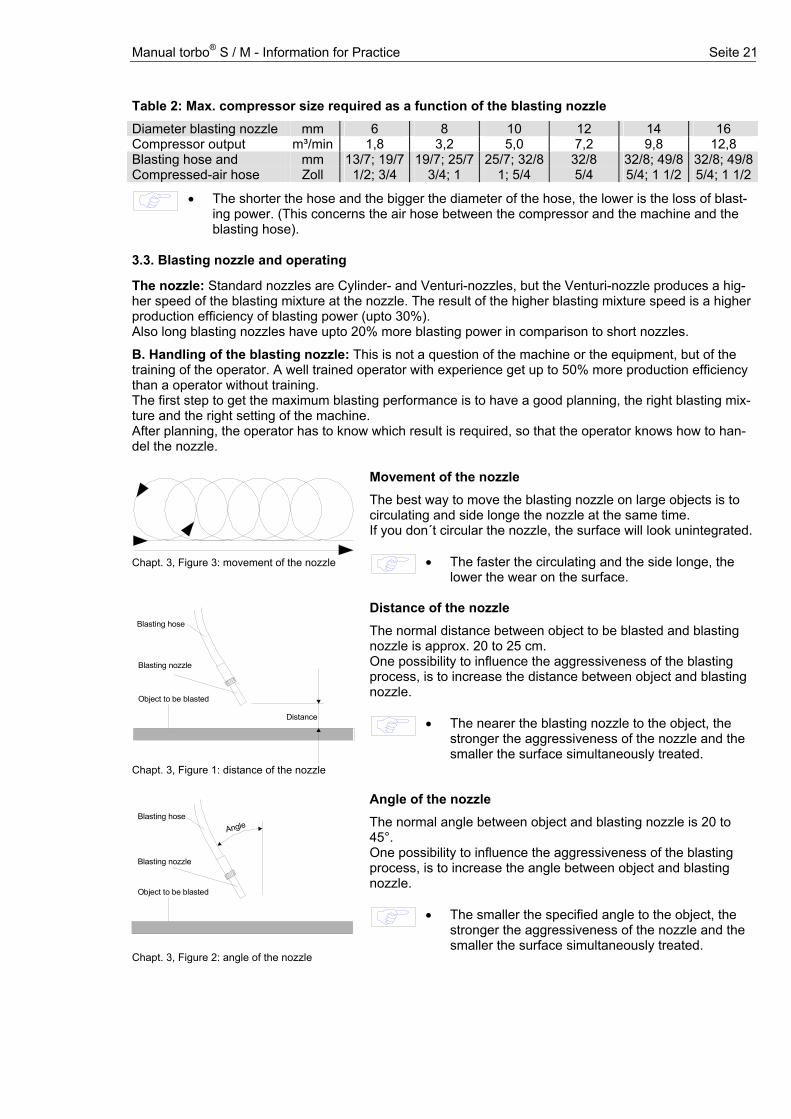
Movement of the nozzle
The best way to move the blasting nozzle on large objects is to circulating and side longe the nozzle at the same time. If you don´t circular the nozzle, the surface will look unintegrated.
Chapt. 3, Figure 3: movement of the nozzle
• The faster the circulating and the side longe, the lower the wear on the surface.
Distance of the nozzle
The normal distance between object to be blasted and blasting nozzle is approx. 20 to 25 cm. One possibility to influence the aggressiveness of the blasting process, is to increase the distance between object and blasting nozzle.
Blasting nozzle
Blasting hose
Object to be blasted
Distance
Chapt. 3, Figure 1: distance of the nozzle
• The nearer the blasting nozzle to the object, the stronger the aggressiveness of the nozzle and the smaller the surface simultaneously treated.
Angle of the nozzle
The normal angle between object and blasting nozzle is 20 to 45°. One possibility to influence the aggressiveness of the blasting process, is to increase the angle between object and blasting nozzle.
• The smaller the specified angle to the object, the stronger the aggressiveness of the nozzle and the smaller the surface simultaneously treated.
Blasting nozzle
Blasting hose
Object to be blasted
Angle
Chapt. 3, Figure 2: angle of the nozzle
Manual torbo® S / M - Maintenance Seite 22
4. Maintenance In order to ensure a correct maintenance of the machine it is compulsory that maintenance is
performed only after having read these instructions and by trained personnel.
4.1. Maintenance work look at
section Daily before connecting the machine • cleaning of commpressed-air connections
• cleaning of water connections
---
Weekly • equipment cleaned externally
• cleaning of compressed air und water filter • check gaskets of connecting couplings; if necessary, replace gaskets
4.2. ---
Inspection I • check non-return valves and clean if needed
• check stoppers and counterparts
• check blasting coupling at the machine • check insulation of electric components incl. cable
• check hoses and couplings (pneumatic compressed-air and pressurized water hoses, air and water couplings)
• check connections and screwings for leakproofness • check safety check-valve
• check piston pump for leakproofness and slightly grease it • check dosing valve(s) and clean if necessary
• check manometer(s) for perfect functioning • functional test of the machine
Inspection II Includes all items of inspection I; in addition: • replace filter elements of compressed-air and water filter
• replace dirty and bucked pneumatic hoses
• dosing valve(s) to be cleaned • check electric connections for corrosion
• check function of control valves
• clean and check non-return valves at compressed-air connection • check vessel for leakproofness
• grease hinges, spring in safety check valve and locks
In one-shift-operations the inspection I and inspection II are to be carried through at intervals of 3 to 6 months. Any occurring troubles, faults etc. are to be eliminated immediately by adequately trained personnel; be-for starting the machine again, any defective parts are to be replaced by new original parts.
!
Warnung
• Before beginning any maintenance work, the power, compressed-air and water connections are to be detached and the machine is to be depressurized.
• The machine must be protected from re-start. • Repairs and the inspection I and II may be carried through by adequately trained personnel
only, being at disposal via the torbo-trading partners. • For mobile units with compressors the inspections of the respective manufacturer must be
adhered to for maintenance at the compressor or chassis respectively.
• For a safe operation and a long service life of the machine and its accessories, it must be
adhered to the cleaning and maintenance advises shown in the instructions for operation.
Manual torbo® S / M - Maintenance Seite 23
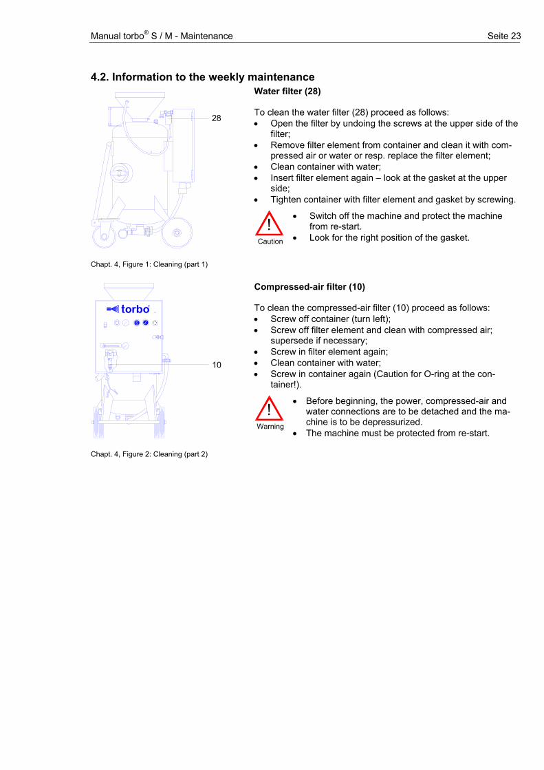
4.2. Information to the weekly maintenance Water filter (28) To clean the water filter (28) proceed as follows: • Open the filter by undoing the screws at the upper side of the
filter; • Remove filter element from container and clean it with com-
pressed air or water or resp. replace the filter element; • Clean container with water; • Insert filter element again – look at the gasket at the upper
side; • Tighten container with filter element and gasket by screwing.
!
Caution
• Switch off the machine and protect the machine from re-start.
• Look for the right position of the gasket.
Compressed-air filter (10) To clean the compressed-air filter (10) proceed as follows: • Screw off container (turn left); • Screw off filter element and clean with compressed air;
supersede if necessary; • Screw in filter element again; • Clean container with water; • Screw in container again (Caution for O-ring at the con-
tainer!).
28
Chapt. 4, Figure 1: Cleaning (part 1)
10
0 , 6
45
D
6 2
1
3S
0
34
6
5 1
0 ,6
2Z
to orb R
Chapt. 4, Figure 2: Cleaning (part 2)
!
Warning
• Before beginning, the power, compressed-air and water connections are to be detached and the ma-chine is to be depressurized.
• The machine must be protected from re-start.
Manual torbo® S / M - Trouble-shooting Seite 24
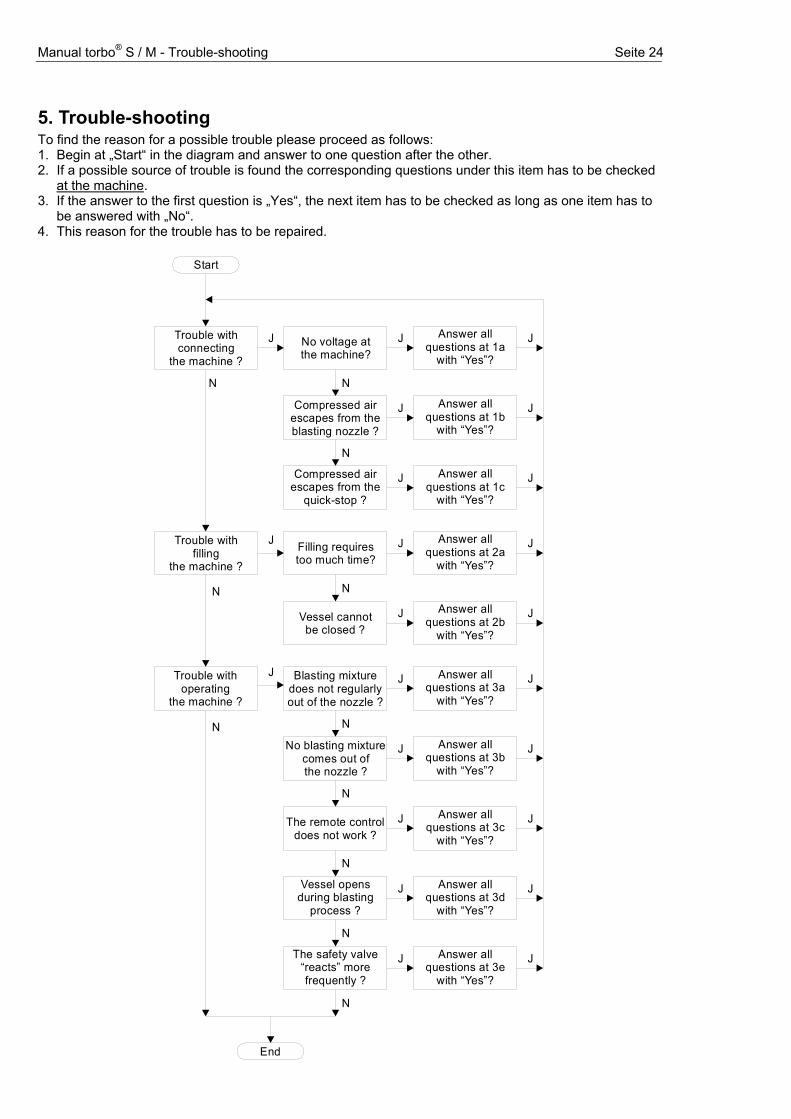
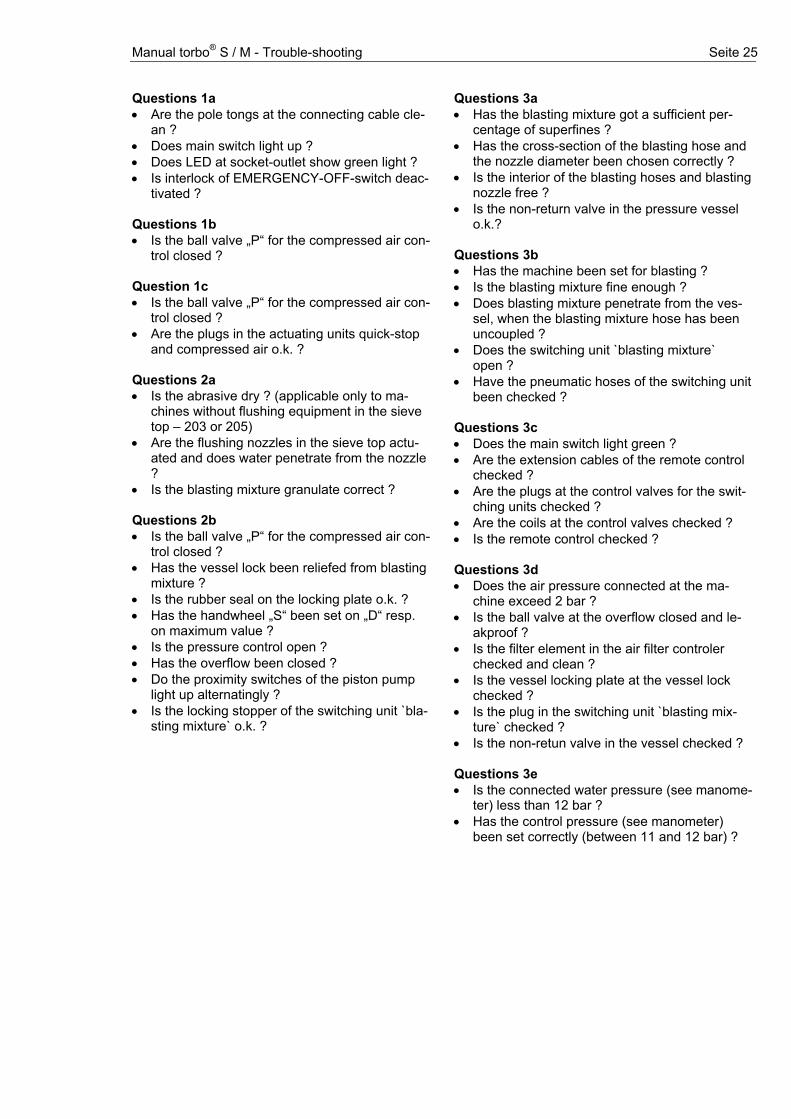
5. Trouble-shooting To find the reason for a possible trouble please proceed as follows: 1. Begin at „Start“ in the diagram and answer to one question after the other. 2. If a possible source of trouble is found the corresponding questions under this item has to be checked
at the machine. 3. If the answer to the first question is „Yes“, the next item has to be checked as long as one item has to
be answered with „No“. 4. This reason for the trouble has to be repaired.
Start
End
Trouble withconnecting
the machine ?No voltage atthe machine?
J
N
J
N
Compressed airescapes from theblasting nozzle ?
N
J
Compressed airescapes from the
quick-stop ?
J
Trouble withfilling
the machine ?Filling requirestoo much time?
J
N
J
N
Vessel cannotbe closed ?
J
Trouble withoperating
the machine ?
Blasting mixturedoes not regularlyout of the nozzle ?
J
N
J
NNo blasting mixture
comes out ofthe nozzle ?
N
J
The remote controldoes not work ?
N
J
Vessel opensduring blasting
process ?
N
J
The safety valve“reacts” morefrequently ?
J
N
Answer all questions at 1a
with “Yes”?
J
J
J
J
J
J
J
J
J
J
Answer all questions at 1b
with “Yes”?
Answer all questions at 1c
with “Yes”?
Answer all questions at 2a
with “Yes”?
Answer all questions at 2b
with “Yes”?
Answer all questions at 3a
with “Yes”?
Answer all questions at 3b
with “Yes”?
Answer all questions at 3c
with “Yes”?
Answer all questions at 3d
with “Yes”?
Answer all questions at 3e
with “Yes”?
Manual torbo® S / M - Trouble-shooting Seite 25
Questions 1a • Are the pole tongs at the connecting cable cle-
an ? • Does main switch light up ? • Does LED at socket-outlet show green light ? • Is interlock of EMERGENCY-OFF-switch deac-
tivated ? Questions 1b • Is the ball valve „P“ for the compressed air con-
trol closed ? Question 1c • Is the ball valve „P“ for the compressed air con-
trol closed ? • Are the plugs in the actuating units quick-stop
and compressed air o.k. ? Questions 2a • Is the abrasive dry ? (applicable only to ma-
chines without flushing equipment in the sieve top – 203 or 205)
• Are the flushing nozzles in the sieve top actu-ated and does water penetrate from the nozzle ?
• Is the blasting mixture granulate correct ? Questions 2b • Is the ball valve „P“ for the compressed air con-
trol closed ? • Has the vessel lock been reliefed from blasting
mixture ? • Is the rubber seal on the locking plate o.k. ? • Has the handwheel „S“ been set on „D“ resp.
on maximum value ? • Is the pressure control open ? • Has the overflow been closed ? • Do the proximity switches of the piston pump
light up alternatingly ? • Is the locking stopper of the switching unit `bla-
sting mixture` o.k. ?
Questions 3a • Has the blasting mixture got a sufficient p
centage of superfines ? er-
• Has the cross-section of the blasting hose and the nozzle diameter been chosen correctly ?
• Is the interior of the blasting hoses and blasting nozzle free ?
• Is the non-return valve in the pressure vessel o.k.?
Questions 3b • Has the machine been set for blasting ? • Is the blasting mixture fine enough ? • Does blasting mixture penetrate from the ves-
sel, when the blasting mixture hose has been uncoupled ?
• Does the switching unit `blasting mixture` open ?
• Have the pneumatic hoses of the switching unit been checked ?
Questions 3c • Does the main switch light green ? • Are the extension cables of the remote control
checked ? • Are the plugs at the control valves for the swit-
ching units checked ? • Are the coils at the control valves checked ? • Is the remote control checked ? Questions 3d • Does the air pressure connected at the ma-
chine exceed 2 bar ? • Is the ball valve at the overflow closed and le-
akproof ? • Is the filter element in the air filter controler
checked and clean ? • Is the vessel locking plate at the vessel lock
checked ? • Is the plug in the switching unit `blasting mix-
ture` checked ? • Is the non-retun valve in the vessel checked ? Questions 3e • Is the connected water pressure (see manome-
ter) less than 12 bar ? • Has the control pressure (see manometer)
been set correctly (between 11 and 12 bar) ?
Manual torbo® S / M – Technical Data Seite 26
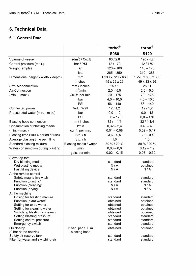
6. Technical Data
6.1. General Data torbo®
S080
torbo® S120
Volume of vessel l (dm3) / Cu. ft 80 / 2,8 120 / 4,2 Control pressure (max.) bar / PSI 12 / 170 12 / 170 Weight (empty) kg
lbs. 120 – 160 265 – 350
140 – 175 310 – 385
Dimensions (height x width x depth) mm inches
1.130 x 720 x 660 45 x 29 x 26
1.220 x 830 x 660 49 x 33 x 26
Size Air-connection mm / inches 25 / 1 25 / 1 Air Connection (min. – max.)
m3/min Cu. ft. per min.
2,0 – 5,0 70 – 175
2,0 – 5,0 70 – 175
bar PSI
4,0 – 10,0 56 – 140
4,0 – 10,0 56 – 140
Connected power Volt / Watt 12 / 1,2 12 / 1,2 Pressurized water (min. - max.) bar
PSI 0,0 – 12
0,0 – 170 0,0 – 12 0,0 – 170
Blasting hose connection mm / inches 32 / 1 1/4 32 / 1 1/4 Consumption of blasting media (min. – max.)
l/min cu. ft. per min.
0,32 – 2,4 0,01 – 0,08
0,48 – 4,8 0,02 – 0,17
Blasting time (100% period of use) Std. / h 3,6 – 0,5 3,8 – 0,4 Average blasting time per filling Std. / h 1,0 1,5 Standard blasting mixture Blasting media / water 80 % / 20 % 80 % / 20 % Water consumption during blasting l/min.
gals. per min. 0,08 – 0,6 0,02 – 0,15
0,12 – 1,2 0,03 – 0,30
Sieve top for: Dry blasting media standard standard Wet blasting media N / A obtained Fast filling device N / A N / A
At the remote control Safety magnetic-switch standard standard Function „blasting“ standard standard Function „cleaning“ N / A N / A Function „drying“ N / A N / A
At the machine Dosing for blasting mixture standard standard Function „extra water“ obtained obtained Setting for extra water obtained obtained Setting for cleaning water obtained obtained Switching blasting to cleaning obtained obtained Setting blasting pressure standard standard Setting control pressure standard standard Emergency-switch standard standard
Quick-stop (0 bar at the nozzle)
3 sec. per 100 m blasting hose
obtained obtained
Safety air reserve tank standard standard Filter for water and switching-air standard standard
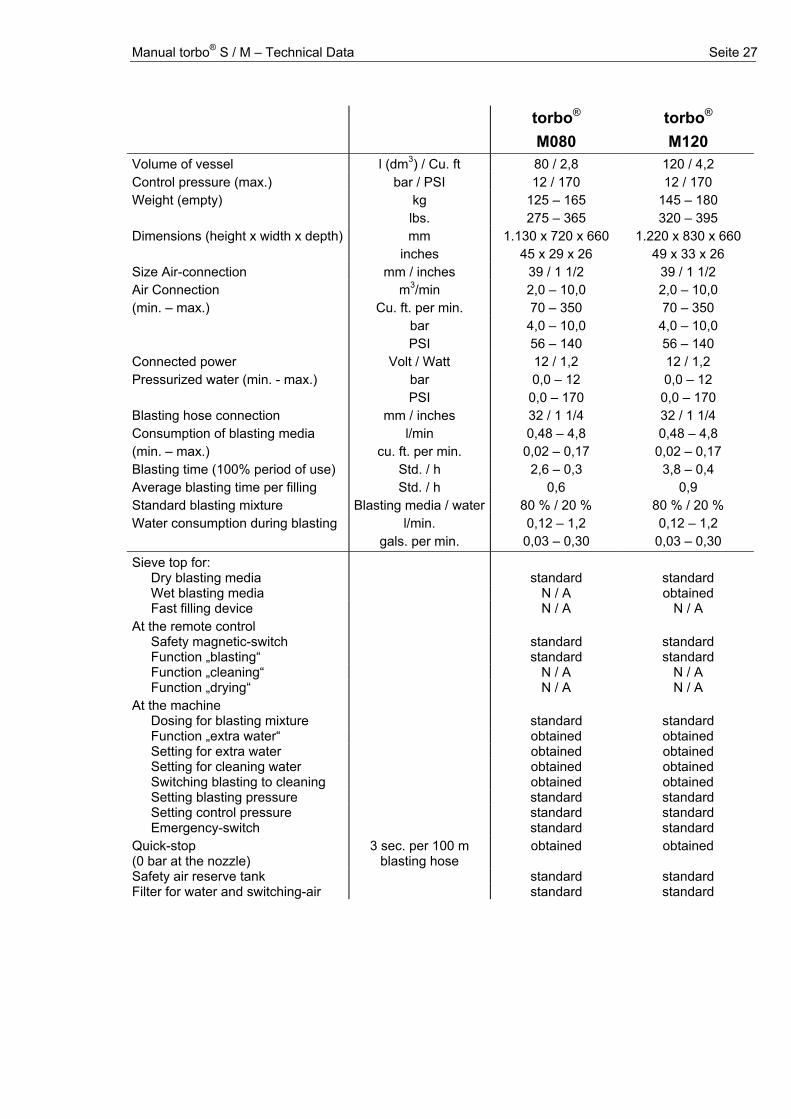
Manual torbo® S / M – Technical Data Seite 27
torbo®
M080
torbo® M120
Volume of vessel l (dm3) / Cu. ft 80 / 2,8 120 / 4,2 Control pressure (max.) bar / PSI 12 / 170 12 / 170 Weight (empty) kg
lbs. 125 – 165 275 – 365
145 – 180 320 – 395
Dimensions (height x width x depth) mm inches
1.130 x 720 x 660 45 x 29 x 26
1.220 x 830 x 660 49 x 33 x 26
Size Air-connection mm / inches 39 / 1 1/2 39 / 1 1/2 Air Connection (min. – max.)
m3/min Cu. ft. per min.
2,0 – 10,0 70 – 350
2,0 – 10,0 70 – 350
bar PSI
4,0 – 10,0 56 – 140
4,0 – 10,0 56 – 140
Connected power Volt / Watt 12 / 1,2 12 / 1,2 Pressurized water (min. - max.) bar
PSI 0,0 – 12
0,0 – 170 0,0 – 12 0,0 – 170
Blasting hose connection mm / inches 32 / 1 1/4 32 / 1 1/4 Consumption of blasting media (min. – max.)
l/min cu. ft. per min.
0,48 – 4,8 0,02 – 0,17
0,48 – 4,8 0,02 – 0,17
Blasting time (100% period of use) Std. / h 2,6 – 0,3 3,8 – 0,4 Average blasting time per filling Std. / h 0,6 0,9 Standard blasting mixture Blasting media / water 80 % / 20 % 80 % / 20 % Water consumption during blasting l/min.
gals. per min. 0,12 – 1,2 0,03 – 0,30
0,12 – 1,2 0,03 – 0,30
Sieve top for: Dry blasting media standard standard Wet blasting media N / A obtained Fast filling device N / A N / A
At the remote control Safety magnetic-switch standard standard Function „blasting“ standard standard Function „cleaning“ N / A N / A Function „drying“ N / A N / A
At the machine Dosing for blasting mixture standard standard Function „extra water“ obtained obtained Setting for extra water obtained obtained Setting for cleaning water obtained obtained Switching blasting to cleaning obtained obtained Setting blasting pressure standard standard Setting control pressure standard standard Emergency-switch standard standard
Quick-stop (0 bar at the nozzle)
3 sec. per 100 m blasting hose
obtained obtained
Safety air reserve tank standard standard Filter for water and switching-air standard standard

Manual torbo® S / M – Technical Data Seite 28
6.2. Wiring scheme
D1
Si1
LED1
R1
12 Volt Socket
6
21
3
54
T1
D2 Ty1 LED2 NS1
Remote Control FB S99
4
65
321
S1 K1
Si2 LED3
D3
Re1
Powerboxr S02
Controllboard S99
M SV1
K3Connection Solenoid, Switching-units
12
3
4
Emergency-off
123
6 2 135 4 K2
123
R2
Legend D1 Diode 1 N 5400 D2 Diode 1 N 4007 K1-2 Coupling, IP 65 in closed state acc. to DIN 40 050 K3 Coupling, IP 65 LED1 LED (red/green), 4,5 V, 11 mA LED2-3 LED (green), 12 V, 11 mA M SV1 Magnetic coil, Solenoid 12 V DC NS1 Proximity switch R1-2 Resistor 560 Ohm, 1/4 W Re1 Relay, 2xUM, 150 V DC/AC, 1,25 A, 30 W / 50 VA S1 Plug, IP 65 in closed state acc. to DIN 40 050 Si1-2 Fuse, Poly-Switch, 50 V, IH = 1,6 A (= nominal current), IS = 2,4 A T1 Push-button; 42 V, 100 mA (max. 3 VA); IEC 529 Ty1 Thyristor C 106
S2
M SV1
K2
123
123
Connection Solenoid 1 (pump)
S3
M SV2
K3
123
123
Connection Solenoid 2 (pump)NS2NS1
4
65
321S1
Piston-pump 02
Legend K2-3 Coupling, IP 65 M SV1-2 Magnetic coil, Solenoid 12 V DC NS1-2 Proximity switch S1 Plug, IP 65 in shot condition concurring with DIN 40050
Manual torbo® S / M – Technical Data Seite 29
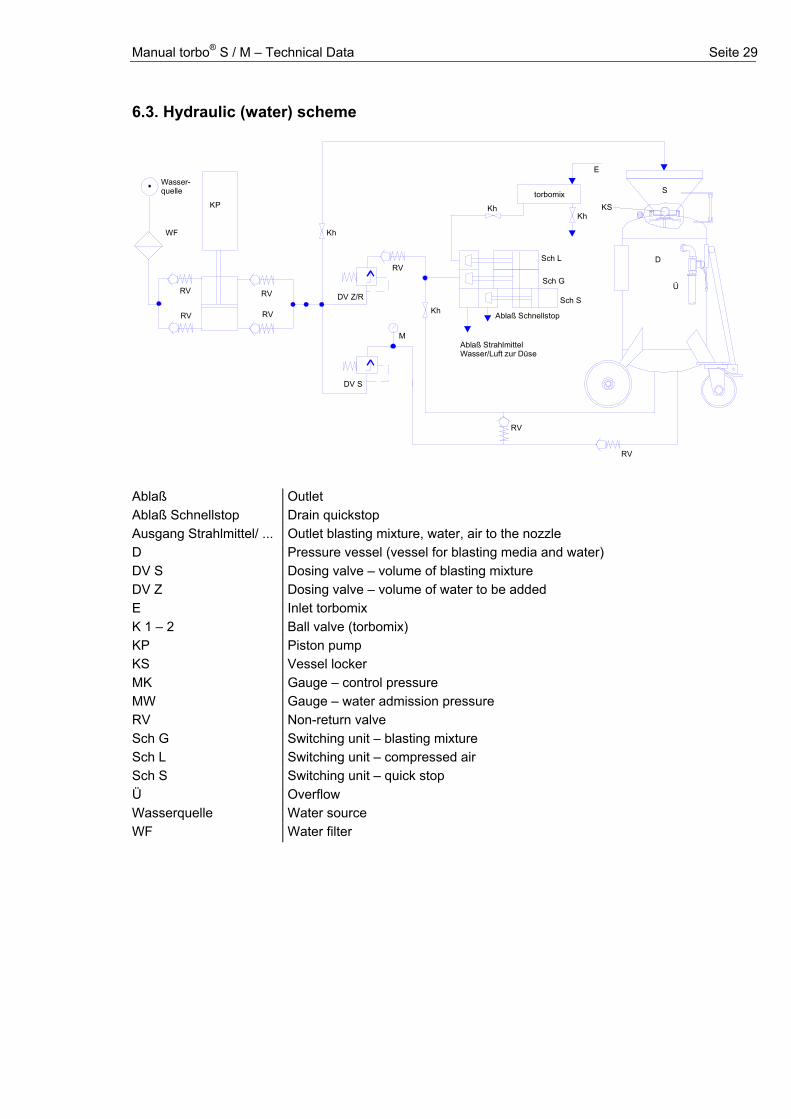
6.3. Hydraulic (water) scheme
Wasser-quelle
WF
RV
RV
KP
RV
RV
DV Z/R
RV
M
DV S
RV
RV
Sch G
Sch S
Ablaß Schnellstop
Ablaß StrahlmittelWasser/Luft zur Düse
S
KS
D
Ü
Sch L
Kh
E
torbomix
Kh
Kh
Kh
Ablaß Outlet Ablaß Schnellstop Drain quickstop Ausgang Strahlmittel/ ... Outlet blasting mixture, water, air to the nozzle D Pressure vessel (vessel for blasting media and water) DV S Dosing valve – volume of blasting mixture DV Z Dosing valve – volume of water to be added E Inlet torbomix K 1 – 2 Ball valve (torbomix) KP Piston pump KS Vessel locker MK Gauge – control pressure MW Gauge – water admission pressure RV Non-return valve Sch G Switching unit – blasting mixture Sch L Switching unit – compressed air Sch S Switching unit – quick stop Ü Overflow Wasserquelle Water source WF Water filter
Manual torbo® S / M – Technical Data Seite 30
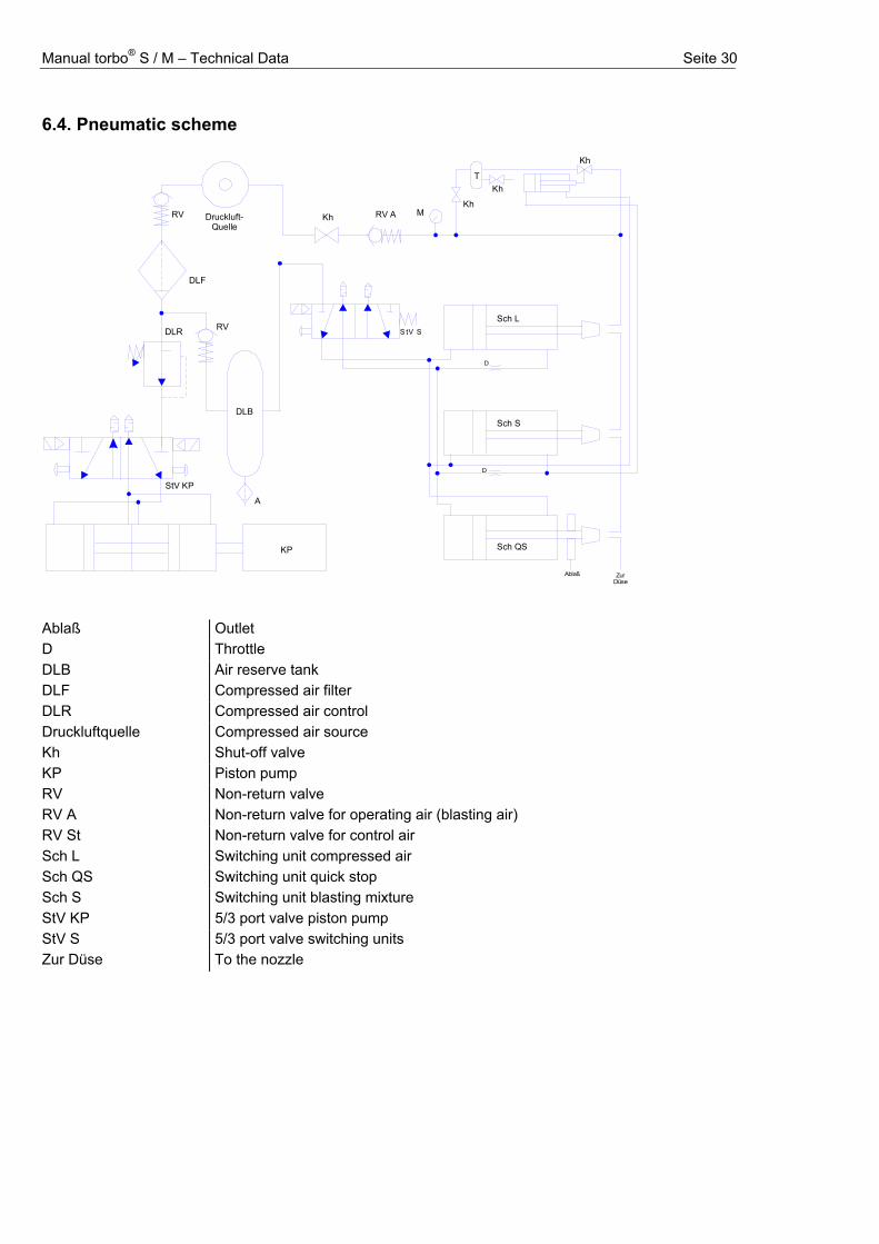
6.4. Pneumatic scheme
KP
StV KP
DLR
DLF
DLB
A
T
Druckluft-Quelle
KhKh
Kh
M
Kh
RV ARV
S tV SRV
Sch S
Sch L
D
D
Sch QS
ZurDüse
Ablaß Ablaß Outlet D Throttle DLB Air reserve tank DLF Compressed air filter DLR Compressed air control Druckluftquelle Compressed air source Kh Shut-off valve KP Piston pump RV Non-return valve RV A Non-return valve for operating air (blasting air) RV St Non-return valve for control air Sch L Switching unit compressed air Sch QS Switching unit quick stop Sch S Switching unit blasting mixture StV KP 5/3 port valve piston pump StV S 5/3 port valve switching units Zur Düse To the nozzle

Manual torbo® S / M – Technical Data Seite 31

Manual torbo® S/ M – Headword contents Seite 32
Manual torbo® S/ M – Headword contents Seite 33
Headword contents Adjustments and settings, 19 Basic Instructions, 6 Basic Safety Instructions, 7 Blasting hose - Connection, 10, 26 Blasting mixture, lock at dosage Blasting pressure, lock at dosage Blasting nozzle, lock at nozzle Code of Practice, 5 Components for Operation, 11 Compressed-air supply, 10 Compressor size, 21, 26 Connecting the Machine, 13 Connections, 10 Data of the Machine, 5 Dosage - Blasting mixture, 11, 20, 26 - Blasting pressure, 20, 26 - Directional data for settings, 20 - Extra Water, 11, 20, 26 Extra Water, lock at dosage Filling the machine, 14 Filter, 23 Frost precaution in winter, 18 Information for Practice, 19 Instructions for Operation, 10 Instructions for Transport, 12 Maintenance, 22 - weekly, 23 - Filter, 23 Normal Operation, 14 Nozzle, 13 - Handling, 21 - Size, 21 Operating Instructions, 13 Overflow port, 10 Power supply, 10, 26 Practice - Blasting result, 19 - Power blasting, 19 - Soft blasting, 19 Pressure control - Control pressure, 11, 26 - Blasting pressure, 11 Remote control, 11 - Connection, 10 - electric remote control, 15 - Operating, 15, 16 - pneumatic remote control, 16 Setting up the machine, 15 Switching blasting-cleaning-drying, 11, 16 Switching off the machine, 17 Technical Data, 26 Trouble-shooting, 24 Water supply, 10, 11