Embed Size (px)
DESCRIPTION
Industrial switch
Citation preview
Galvani cInsulation
TransientProtection
BalancedTransmission
CEApproved
Galvani cInsulation
TransientProtection
BalancedTransmission
CEApproved
Galvani cInsulation
TransientProtection
BalancedTransmission
CEApproved
Galvani cInsulation
TransientProtection
BalancedTransmission
CEApproved
Galvanic Isolation
Transient Protection
Balanced Transmission
CE Approved
RS-422/485 Repeater Répéteur RS-422/485
INSTALLATIONSANVISNINGINSTALLATION MANUAL
INSTALLATIONS ANLEITUNG MANUEL D’INSTALLATION
6153-2004
www.westermo.com
RD-48
LV/HV
©W
este
rmo
Tele
indu
stri
AB
• R
EV.
D
RE
V.D
615
3-20
04
2011
-01
Wes
term
o Te
lein
dust
ri A
B, S
wed
en –
A B
eije
r El
ectr
onic
s G
roup
Com
pany
GB.16 6153-2004
Contents
1. Introduction ............................................................................................................................................................ 17
2. Safety ............................................................................................................................................................................... 17
3. Approvals .................................................................................................................................................................... 173.1 Declaration of Conformity .................................................................................................................... 18
4. Specifications ........................................................................................................................................................ 194.1 Connections ...................................................................................................................................................... 194.2 Insulation between interfaces ............................................................................................................. 194.3 Climatic environment ............................................................................................................................... 194.4 Mechanics ........................................................................................................................................................... 20
5. Maintenance ........................................................................................................................................................... 20
6. Installation ....................................................................................................................................................... 20–246.1 Mounting/Removal ....................................................................................................................................... 206.2 Connections ...................................................................................................................................................... 21
6.2.1 Power (RD-48 HV) ........................................................................................................................... 226.2.2 Power (RD-48 LV/RD-48 LV TEMP) .................................................................................... 226.2.3 Line A RS-422/485 ............................................................................................................................ 226.2.4 Line B RS-422/485 ............................................................................................................................ 22
6.3 Indicators ............................................................................................................................................................ 226.3.1 LED indicators .................................................................................................................................... 22
6.4 DIP switch settings ............................................................................................................................ 23–25
7. Functional description .................................................................................................................... 26–277.1 Operating modes .......................................................................................................................................... 267.2 Selection of data rate/format ............................................................................................................. 277.3 Setting and retiming .................................................................................................................................. 277.4 Setting and anti-blocking ....................................................................................................................... 277.5 Selection of RS-422/485 setting ........................................................................................................ 27
8. Block diagram ...................................................................................................................................................... 28
9. Application example ................................................................................................................................... 29
GB.176153-2004
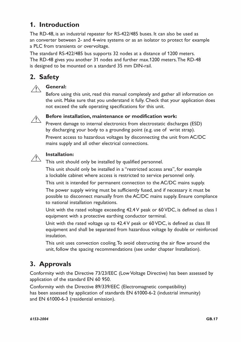
1. IntroductionThe RD-48, is an industrial repeater for RS-422/485 buses. It can also be used as an converter between 2- and 4-wire systems or as an isolator to protect for example a PLC from transients or overvoltage.
The standard RS-422/485 bus supports 32 nodes at a distance of 1200 meters.The RD-48 gives you another 31 nodes and further max.1200 meters.The RD-48 is designed to be mounted on a standard 35 mm DIN-rail.
2. SafetyGeneral:
Before using this unit, read this manual completely and gather all information onthe unit. Make sure that you understand it fully. Check that your application doesnot exceed the safe operating specifications for this unit.
Before installation, maintenance or modification work:
Prevent damage to internal electronics from electrostatic discharges (ESD) by discharging your body to a grounding point (e.g. use of wrist strap).
Prevent access to hazardous voltages by disconnecting the unit from AC/DC mains supply and all other electrical connections.
Installation:
This unit should only be installed by qualified personnel.
This unit should only be installed in a “restricted access area”, for example a lockable cabinet where access is restricted to service personnel only.
This unit is intended for permanent connection to the AC/DC mains supply.
The power supply wiring must be sufficiently fused, and if necessary it must bepossible to disconnect manually from the AC/DC mains supply. Ensure complianceto national installation regulations.
Unit with the rated voltage exceeding 42.4 V peak or 60 VDC, is defined as class Iequipment with a protective earthing conductor terminal.
Unit with the rated voltage up to 42.4 V peak or 60 VDC, is defined as class IIIequipment and shall be separated from hazardous voltage by double or reinforcedinsulation.
This unit uses convection cooling.To avoid obstructing the air flow around theunit, follow the spacing recommendations (see under chapter Installation).
3. ApprovalsConformity with the Directive 73/23/EEC (Low Voltage Directive) has been assessed byapplication of the standard EN 60 950.
Conformity with the Directive 89/339/EEC (Electromagnetic compatibility) has been assessed by application of standards EN 61000-6-2 (industrial immunity) and EN 61000-6-3 (residential emission).
!
!
!
GB.18 6153-2004
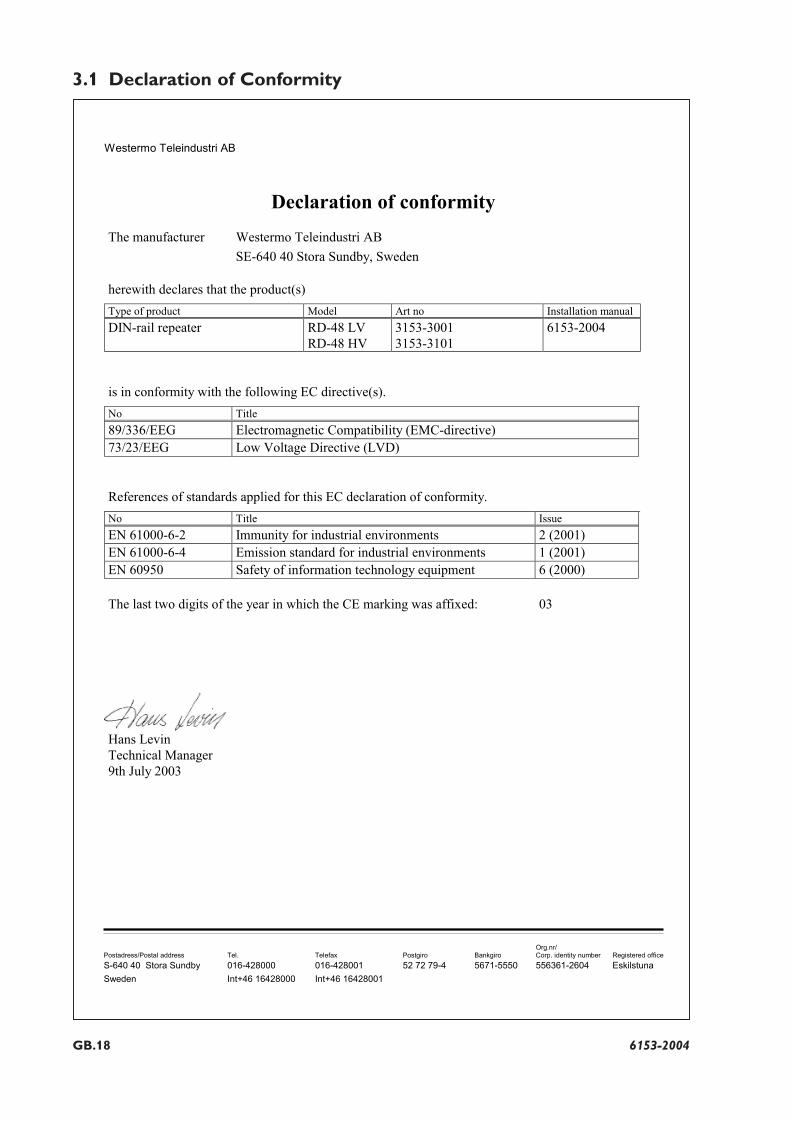
3.1 Declaration of Conformity
Westermo Teleindustri AB
Declaration of conformity
The manufacturer Westermo Teleindustri AB
SE-640 40 Stora Sundby, Sweden
herewith declares that the product(s)
Type of product Model Art no Installation manual
DIN-rail repeater RD-48 LVRD-48 HV
3153-30013153-3101
6153-2004
is in conformity with the following EC directive(s).
No Title
89/336/EEG Electromagnetic Compatibility (EMC-directive)73/23/EEG Low Voltage Directive (LVD)
References of standards applied for this EC declaration of conformity.
No Title Issue
EN 61000-6-2 Immunity for industrial environments 2 (2001)EN 61000-6-4 Emission standard for industrial environments 1 (2001)EN 60950 Safety of information technology equipment 6 (2000)
The last two digits of the year in which the CE marking was affixed: 03
Hans LevinTechnical Manager9th July 2003
Org.nr/Postadress/Postal address Tel. Telefax Postgiro Bankgiro Corp. identity number Registered office
S-640 40 Stora Sundby 016-428000 016-428001 52 72 79-4 5671-5550 556361-2604 Eskilstuna
Sweden Int+46 16428000 Int+46 16428001
GB.196153-2004
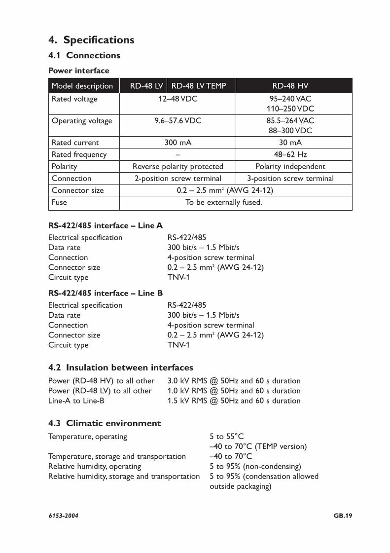
Model description RD-48 LV RD-48 LV TEMP RD-48 HV
Rated voltage 12–48 VDC 95–240 VAC110–250 VDC
Operating voltage 9.6–57.6 VDC 85.5–264 VAC88–300 VDC
Rated current 300 mA 30 mA
Rated frequency – 48–62 Hz
Polarity Reverse polarity protected Polarity independent
Connection 2-position screw terminal 3-position screw terminal
Connector size 0.2 – 2.5 mm2 (AWG 24-12)
Fuse To be externally fused.
4. Specifications4.1 Connections
Power interface
RS-422/485 interface – Line A
Electrical specification RS-422/485Data rate 300 bit/s – 1.5 Mbit/sConnection 4-position screw terminalConnector size 0.2 – 2.5 mm2 (AWG 24-12)Circuit type TNV-1
RS-422/485 interface – Line B
Electrical specification RS-422/485Data rate 300 bit/s – 1.5 Mbit/sConnection 4-position screw terminalConnector size 0.2 – 2.5 mm2 (AWG 24-12)Circuit type TNV-1
4.2 Insulation between interfacesPower (RD-48 HV) to all other 3.0 kV RMS @ 50Hz and 60 s duration Power (RD-48 LV) to all other 1.0 kV RMS @ 50Hz and 60 s durationLine-A to Line-B 1.5 kV RMS @ 50Hz and 60 s duration
4.3 Climatic environmentTemperature, operating 5 to 55°C
–40 to 70°C (TEMP version)Temperature, storage and transportation –40 to 70°CRelative humidity, operating 5 to 95% (non-condensing)Relative humidity, storage and transportation 5 to 95% (condensation allowed
outside packaging)
GB.20 6153-2004
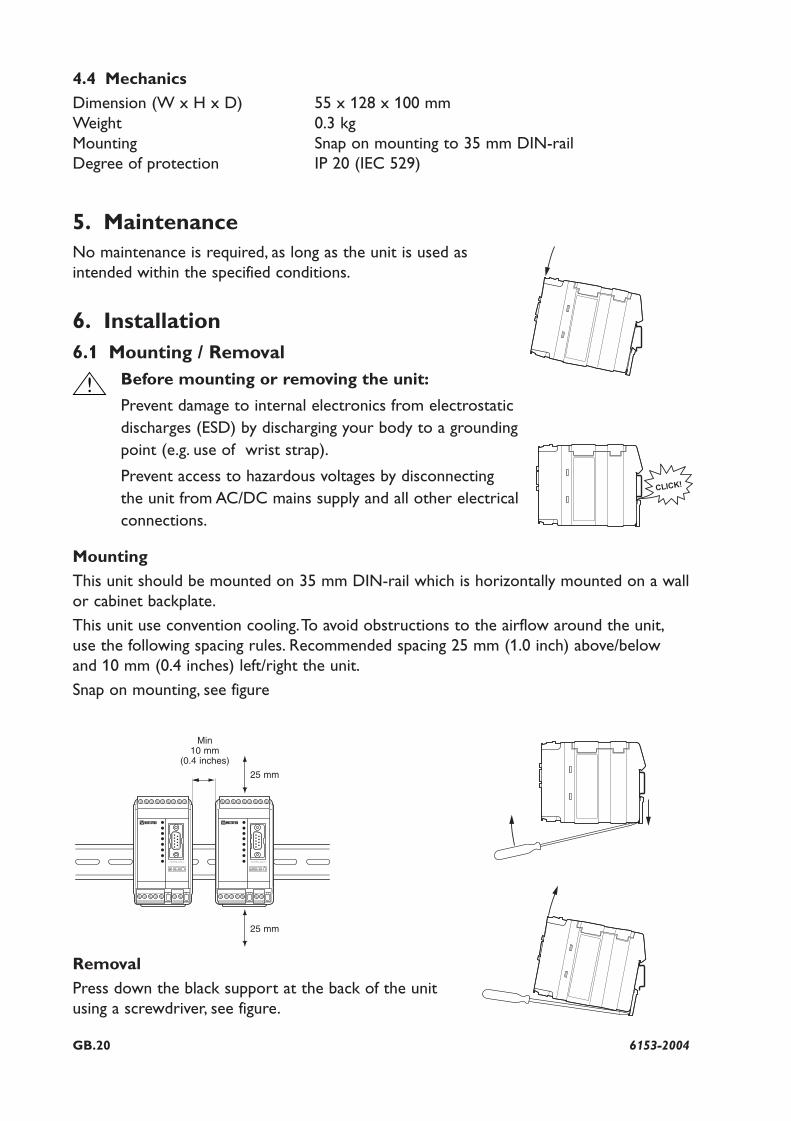
5. MaintenanceNo maintenance is required, as long as the unit is used asintended within the specified conditions.
6. Installation6.1 Mounting / Removal
Before mounting or removing the unit:
Prevent damage to internal electronics from electrostaticdischarges (ESD) by discharging your body to a groundingpoint (e.g. use of wrist strap).
Prevent access to hazardous voltages by disconnectingthe unit from AC/DC mains supply and all other electricalconnections.
Mounting
This unit should be mounted on 35 mm DIN-rail which is horizontally mounted on a wallor cabinet backplate.
This unit use convention cooling.To avoid obstructions to the airflow around the unit,use the following spacing rules. Recommended spacing 25 mm (1.0 inch) above/belowand 10 mm (0.4 inches) left/right the unit.
Snap on mounting, see figure
Removal
Press down the black support at the back of the unitusing a screwdriver, see figure.
Min 10 mm
(0.4 inches)
4.4 Mechanics
Dimension (W x H x D) 55 x 128 x 100 mmWeight 0.3 kgMounting Snap on mounting to 35 mm DIN-railDegree of protection IP 20 (IEC 529)
CLICK!
!
25 mm
25 mm
GB.216153-2004
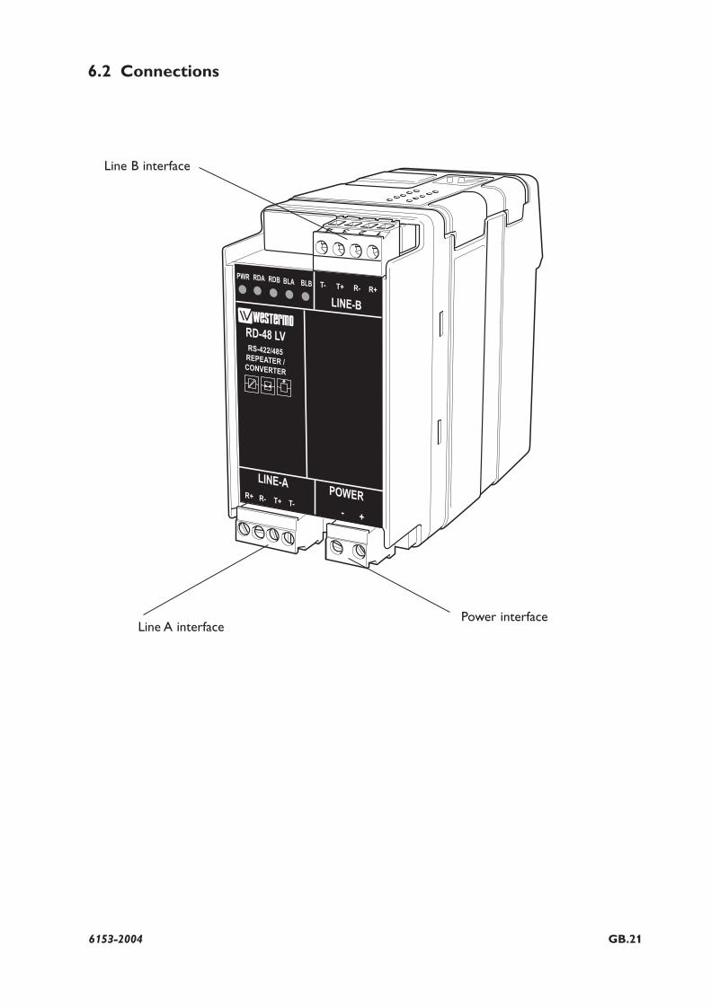
6.2 Connections
Line B interface
Line A interfacePower interface
GB.22 6153-2004
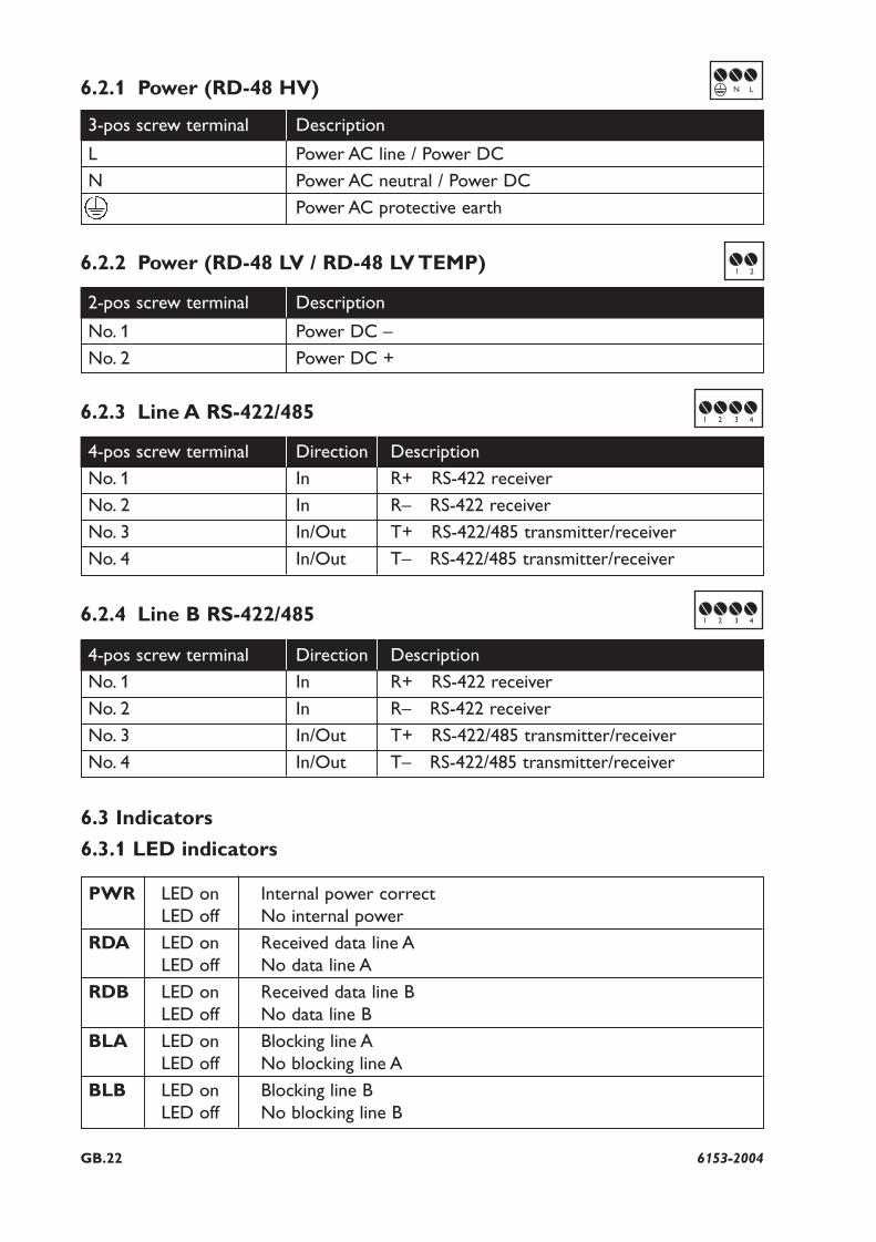
6.2.1 Power (RD-48 HV)
6.2.2 Power (RD-48 LV / RD-48 LV TEMP)
6.2.3 Line A RS-422/485
6.2.4 Line B RS-422/485
3-pos screw terminal Description
L Power AC line / Power DC
N Power AC neutral / Power DC
Power AC protective earth
2-pos screw terminal Description
No. 1 Power DC –
No. 2 Power DC +
4-pos screw terminal Direction Description
No. 1 In R+ RS-422 receiver
No. 2 In R– RS-422 receiver
No. 3 In/Out T+ RS-422/485 transmitter/receiver
No. 4 In/Out T– RS-422/485 transmitter/receiver
4-pos screw terminal Direction Description
No. 1 In R+ RS-422 receiver
No. 2 In R– RS-422 receiver
No. 3 In/Out T+ RS-422/485 transmitter/receiver
No. 4 In/Out T– RS-422/485 transmitter/receiver
6.3 Indicators
6.3.1 LED indicators
PWR LED on Internal power correctLED off No internal power
RDA LED on Received data line ALED off No data line A
RDB LED on Received data line BLED off No data line B
BLA LED on Blocking line ALED off No blocking line A
BLB LED on Blocking line BLED off No blocking line B
N L
1 2
1 2 3 4
1 2 3 4
GB.236153-2004
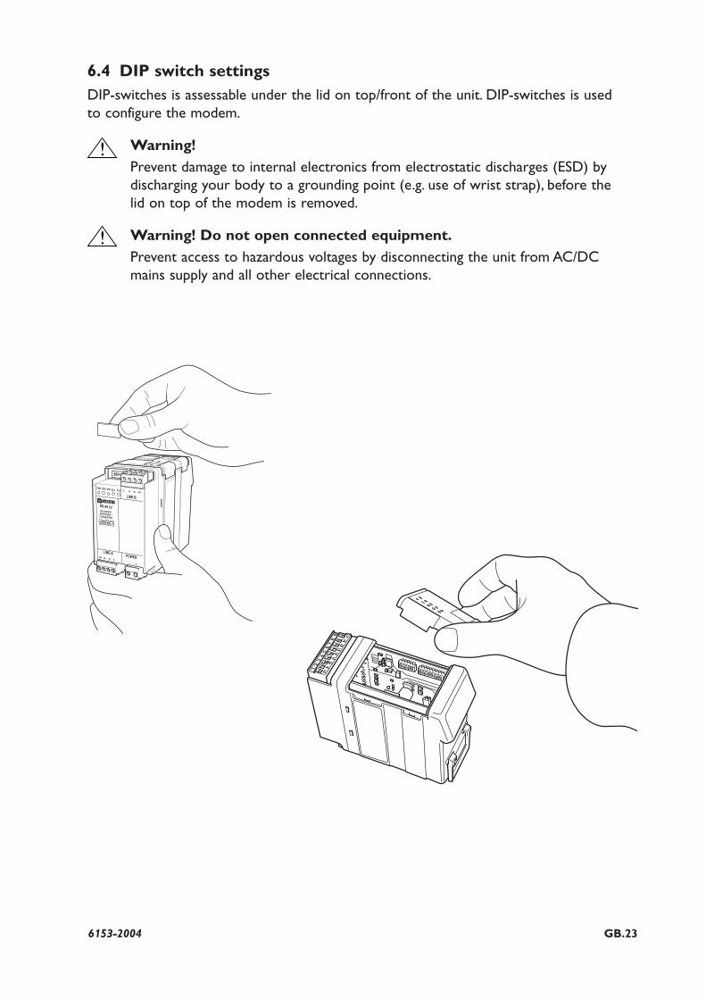
6.4 DIP switch settingsDIP-switches is assessable under the lid on top/front of the unit. DIP-switches is used to configure the modem.
Warning!
Prevent damage to internal electronics from electrostatic discharges (ESD) by discharging your body to a grounding point (e.g. use of wrist strap), before the lid on top of the modem is removed.
Warning! Do not open connected equipment.
Prevent access to hazardous voltages by disconnecting the unit from AC/DCmains supply and all other electrical connections.
!
!
GB.24 6153-2004
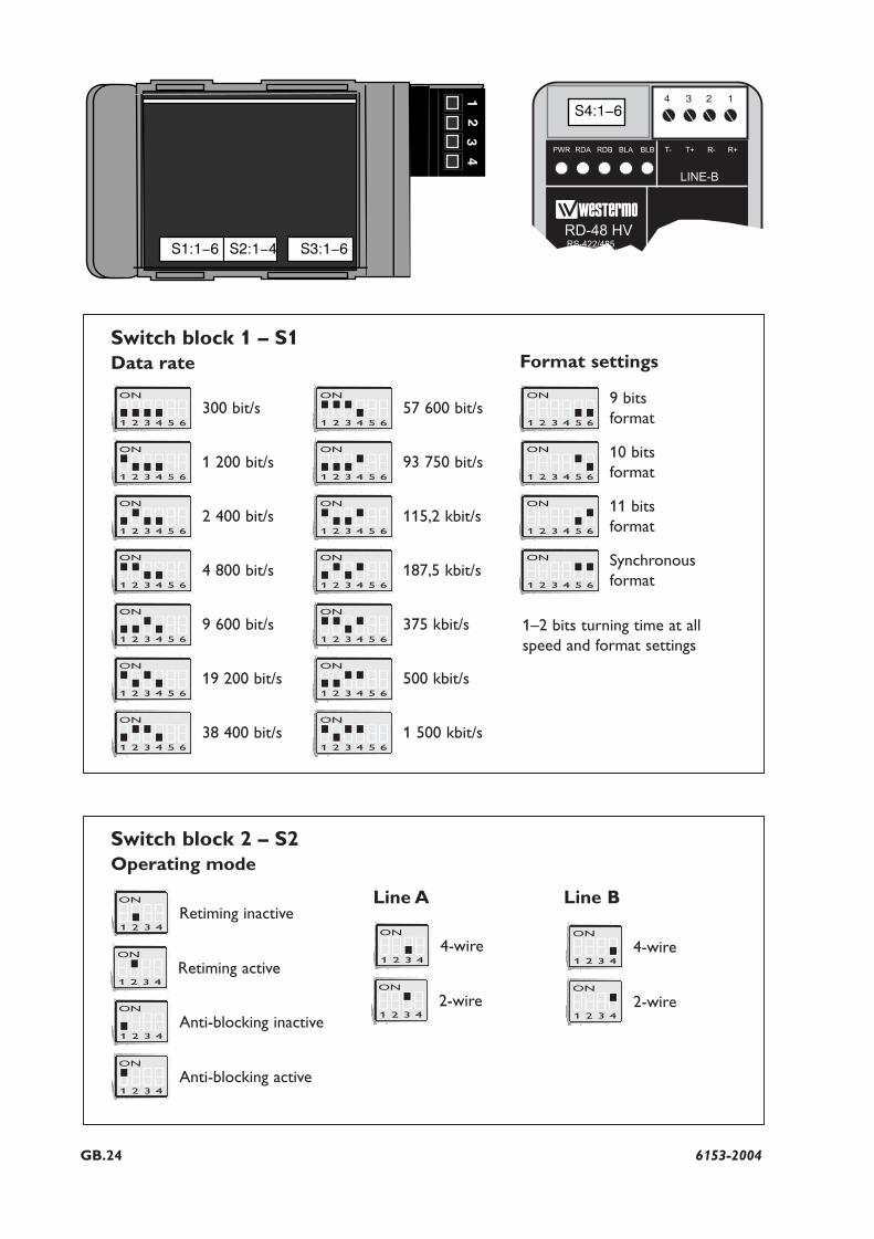
Switch block 2 – S2Operating mode
ON
1 2 3 4
Switch block 1 – S1Data rate
300 bit/sON
1 2 3 4 5 6
1 200 bit/sON
1 2 3 4 5 6
2 400 bit/sON
1 2 3 4 5 6
4 800 bit/sON
1 2 3 4 5 6
9 600 bit/sON
1 2 3 4 5 6
19 200 bit/sON
1 2 3 4 5 6
38 400 bit/sON
1 2 3 4 5 6
57 600 bit/s
Retiming inactive
ON
1 2 3 4
Retiming active
ON
1 2 3 4
Anti-blocking inactive
ON
1 2 3 4
Anti-blocking active
ON
1 2 3 4
4-wire
ON
1 2 3 4
2-wire
ON
1 2 3 4
4-wire
ON
1 2 3 4
2-wire
ON
1 2 3 4 5 6
9 bits format
ON
1 2 3 4 5 6
10 bits format
ON
1 2 3 4 5 6
11 bitsformat
ON
1 2 3 4 5 6
Synchronousformat
1–2 bits turning time at allspeed and format settings
ON
1 2 3 4 5 6
93 750 bit/sON
1 2 3 4 5 6
115,2 kbit/sON
1 2 3 4 5 6
187,5 kbit/sON
1 2 3 4 5 6
375 kbit/sON
1 2 3 4 5 6
500 kbit/sON
1 2 3 4 5 6
1 500 kbit/sON
1 2 3 4 5 6
Format settings
Line A Line B
1234S4:1-6
12
34
S1:1-6 S2:1-4 S3:1-6
GB.256153-2004
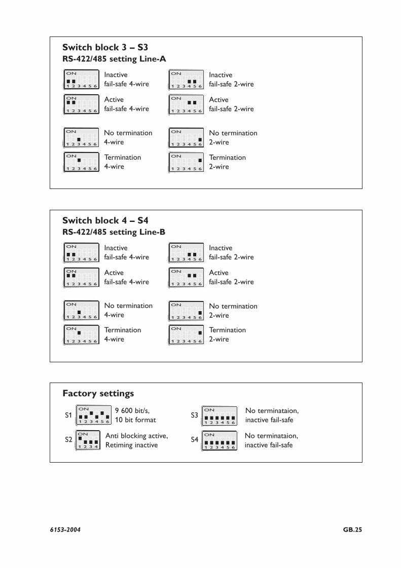
Factory settings
Switch block 3 – S3RS-422/485 setting Line-A
Inactive fail-safe 4-wire
ON
1 2 3 4 5 6
Active fail-safe 4-wire
ON
1 2 3 4 5 6
Termination4-wire
ON
1 2 3 4 5 6
Termination2-wire
ON
1 2 3 4 5 6
No termination2-wire
ON
1 2 3 4 5 6
No termination4-wire
ON
1 2 3 4 5 6
Inactive fail-safe 2-wire
ON
1 2 3 4 5 6
Active fail-safe 2-wire
ON
1 2 3 4 5 6
Switch block 4 – S4RS-422/485 setting Line-B
Inactive fail-safe 4-wire
ON
1 2 3 4 5 6
Active fail-safe 4-wire
ON
1 2 3 4 5 6
Termination4-wire
ON
1 2 3 4 5 6
Termination2-wire
ON
1 2 3 4 5 6
No termination2-wire
ON
1 2 3 4 5 6
No termination4-wire
ON
1 2 3 4 5 6
Inactive fail-safe 2-wire
ON
1 2 3 4 5 6
Active fail-safe 2-wire
ON
1 2 3 4 5 6
ON
1 2 3 4 5 6
ON
1 2 3 4 5 6
ON
1 2 3 4 5 6
9 600 bit/s,10 bit format
S1
S2
S3
S4ON
1 2 3 4
Anti blocking active,Retiming inactive
No terminataion,inactive fail-safe
No terminataion,inactive fail-safe
GB.26 6153-2004
7. Functional description
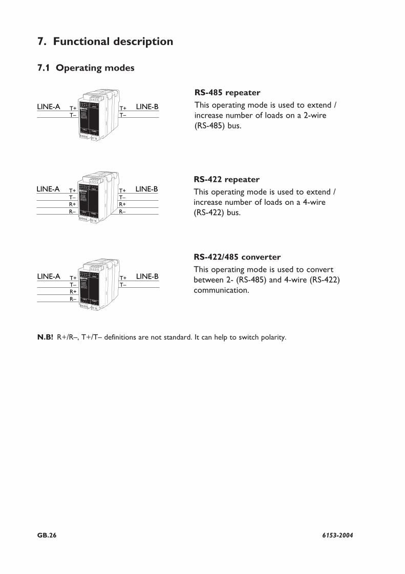
7.1 Operating modes
RS-485 repeater
This operating mode is used to extend /increase number of loads on a 2-wire (RS-485) bus.
RS-422 repeater
This operating mode is used to extend /increase number of loads on a 4-wire (RS-422) bus.
RS-422/485 converter
This operating mode is used to convertbetween 2- (RS-485) and 4-wire (RS-422) communication.
1234
LINE-A LINE-BT+T–
T+T–
1234
LINE-A LINE-BT+T–
T+T–
R+ R+R– R–
1234
LINE-A LINE-BT+T–
T+T–
R+R–
N.B! R+/R–, T+/T– definitions are not standard. It can help to switch polarity.
GB.276153-2004
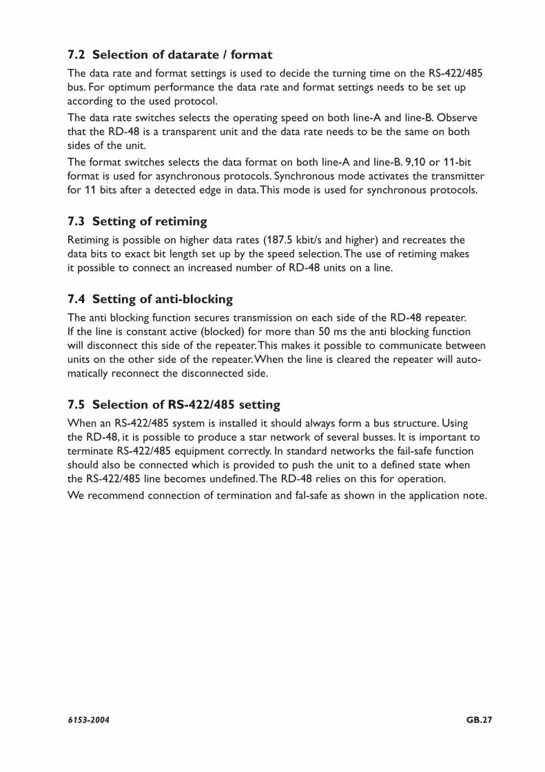
7.2 Selection of datarate / formatThe data rate and format settings is used to decide the turning time on the RS-422/485bus. For optimum performance the data rate and format settings needs to be set upaccording to the used protocol.
The data rate switches selects the operating speed on both line-A and line-B. Observethat the RD-48 is a transparent unit and the data rate needs to be the same on bothsides of the unit.
The format switches selects the data format on both line-A and line-B. 9,10 or 11-bit format is used for asynchronous protocols. Synchronous mode activates the transmitterfor 11 bits after a detected edge in data.This mode is used for synchronous protocols.
7.3 Setting of retimingRetiming is possible on higher data rates (187.5 kbit/s and higher) and recreates the data bits to exact bit length set up by the speed selection.The use of retiming makes it possible to connect an increased number of RD-48 units on a line.
7.4 Setting of anti-blockingThe anti blocking function secures transmission on each side of the RD-48 repeater.If the line is constant active (blocked) for more than 50 ms the anti blocking function will disconnect this side of the repeater.This makes it possible to communicate betweenunits on the other side of the repeater.When the line is cleared the repeater will auto-matically reconnect the disconnected side.
7.5 Selection of RS-422/485 setting When an RS-422/485 system is installed it should always form a bus structure. Using the RD-48, it is possible to produce a star network of several busses. It is important toterminate RS-422/485 equipment correctly. In standard networks the fail-safe functionshould also be connected which is provided to push the unit to a defined state when the RS-422/485 line becomes undefined.The RD-48 relies on this for operation.
We recommend connection of termination and fal-safe as shown in the application note.
28 6153-2004
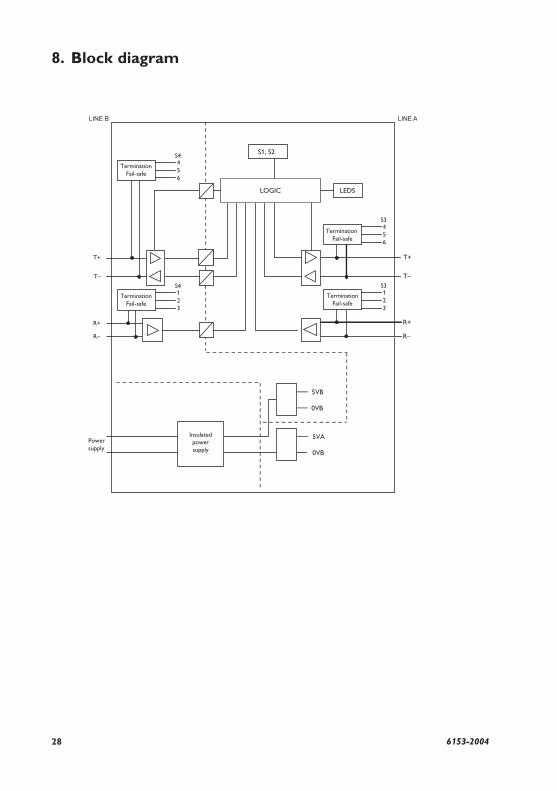
8. Block diagram
123
S4
456
S3
123
S3
Insulatedpowersupply
GB.296153-2004
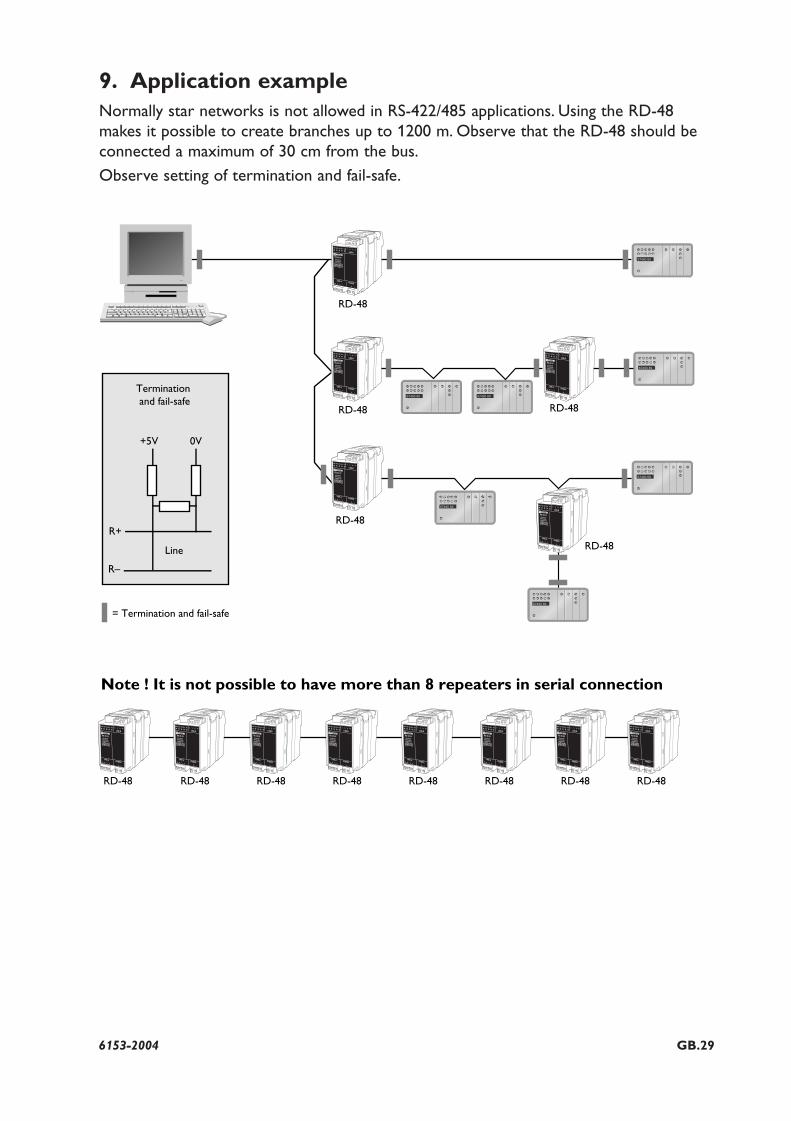
9. Application exampleNormally star networks is not allowed in RS-422/485 applications. Using the RD-48makes it possible to create branches up to 1200 m. Observe that the RD-48 should beconnected a maximum of 30 cm from the bus.
Observe setting of termination and fail-safe.
RD-48
RD-48
RD-48
RD-48RD-48 RD-48 RD-48 RD-48 RD-48 RD-48 RD-48
RD-48
RD-48
+5V 0V
Line
Termination and fail-safe
R–
R+
= Termination and fail-safe
Note ! It is not possible to have more than 8 repeaters in serial connection
1234
1234
1234
12341234
12341234
12341234
12341234
1234
1234
Westermo Teleindustri AB • SE-640 40 Stora Sundby, SwedenPhone +46 16 42 80 00 Fax +46 16 42 80 01
E-mail: [email protected] Westermo Web site: www.westermo.com
Westermo Teleindustri AB have distributors in several countries, contact us for further information.
Sweden
Westermo Data Communications AB Svalgången 1 SE-724 81 Västerås Phone: +46 (0)21 548 08 00 • Fax: +46 (0)21 35 18 50 E-Mail: [email protected]
United Kingdom
Westermo Data Communications Ltd Talisman Business Centre • Duncan Road Park Gate, Southampton • SO31 7GA Phone: +44(0)1489 580-585 • Fax.:+44(0)1489 580586 E-Mail: [email protected]
Germany
Westermo Data Communications GmbH Goethestraße 67, 68753 Waghäusel Tel.: +49(0)7254-95400-0 • Fax.:+49(0)7254-95400-9 E-Mail: [email protected]
France
Westermo Data Communications S.A.R.L. 9 Chemin de Chilly 91160 CHAMPLAN Tél : +33 1 69 10 21 00 • Fax : +33 1 69 10 21 01 E-mail : [email protected]
Singapore
Westermo Data Communications Pte Ltd 2 Soon Wing Road #08-05 Soon Wing Industrial Building Singapore 347893 Phone +65 6743 9801 • Fax +65 6745 0670 E-Mail: [email protected]
North America
Westermo Data Communications 939 N. Plum Grove Road, Suite F Schaumburg Chicago Phone: +1 847 619 6068 Fax: +1 847 619 66 74 E-mail: [email protected]
Taiwan
Westermo Data Communications Co F2, No. 188, Pao-Chiao Rd. Shing-Tien City Taipei 23145 Phone:+886 2 8911 1710 E-mail: [email protected]
Sales Units
RE
V.D
615
3-20
04
2011
-01
Wes
term
o Te
lein
dust
ri A
B, S
wed
en –
A B
eije
r El
ectr
onic
s G
roup
Com
pany


![2004 2:48:45 PM] - Stanford University€¦ · [2/17/2004 2:48:48 PM]](https://img.pdfslide.us/doc/110x75/5f3c37dfbcaafc702502c5b2/2004-24845-pm-stanford-university-2172004-24848-pm.jpg)