Embed Size (px)
Citation preview
Page 1 of 21
ENGINEERING
EVALUATION / FACT SHEET
BACKGROUND INFORMATION
Application No.: R13-3214
Plant ID No.: 095-00042
Applicant: Triad Hunter, LLC
Facility Name: Stewart Winland Production Facility
Location: Middlebourne, Tyler County
SIC Code: 1311
NAICS Code: 211111
Application Type: Construction
Received Date: October 1, 2014
Engineer Assigned: Laura Jennings
Fee Amount: $4,500
Date Received: June 26, 2014 and October 3, 2014
Complete Date: October 17, 2014
Applicant Ad Date: October 8, 2014
Newspaper: Tyler Star News
UTM’s: Easting: 505.10505 km Northing: 4373.28351 km Zone: 17
Lat/Long: Latitude: 39.509167 Longitude: -80.904617
Description: Construction of a natural gas production facility that includes: two (2)
inlet gas compressor gas-fired engines, one (1) flash gas compressor
engine, one (1) 1.0 MMBtu/hr TEG reboiler, eight (8) 1.0 MMBtu/hr
GPU’s, two (2) 2.0 MMBtu/hr GPU’s, five (5) 500-bbl condensate tanks,
five (5) 500-bbl produced water tanks, one (1) truck loading facility, one
(1) dehydration unit, one (1) vapor recovery unit, and four (4) 7.7
MMBtu/hr enclosed combustors used as a back-up to the VRU’s.
DESCRIPTION OF PROCESS
Triad Hunter, LLC plans to install the Stewart Winland Production Facility off of County Road
18/4 in Tyler County, east of Sistersville. The facility will receive natural gas and Produced
west virginia department of environmental protection
Division of Air Quality 601 57th Street SE
Charleston, WV 25304
Phone (304) 926-0475 • FAX: (304) 926-0479
Earl Ray Tomblin, Governor Randy C. Huffman, Cabinet Secretary
www.dep.wv.gov
Fluids from up to nine production wells located on a contiguous well pad. The wells will also be
owned and operated by Triad.
At this new facility, gas produced by the wells will be passed through heated Gas Processing
Units (GPUs) where Produced Fluids (water and condensate) will be separated from the raw gas
stream and further separated into Produced Water and Condensate. The gas will be compressed,
dehydrated and injected into pipelines for transportation to facilities owned by others for further
processing. A small portion of the dehydrated gas will be used as fuel to power facility
equipment. The total amount of gas that will be processed through this facility will vary over
time, but could reach 80 MMSCFD. This application seeks to permit the facility for operation at
this maximum capacity.
The separated raw condensate will be processed through a condensate flash vessel and a
condensate tower where the pressure is reduced to slightly above one atmosphere, thereby
allowing dissolved gases to flash out of the raw condensate. Flash gas from the condensate flash
vessel will be routed to a Flash Gas compressor where the pressure of the gas is sufficiently
increased to allow injection into the primary gas management system as described above.
Vapors separated in the condensate tower are routed to the Vapor Recovery Units (VRU), a gas
compressor driven by an electric motor. The stabilized condensate (up to 1290 BBL per day)
will be accumulated in five 500 BBL aboveground storage tanks prior to transportation, via tank
truck, to a condensate processing facility owned and operated by others.
Produced water (up to 950 BBL per day) will be routed to a separate series of five 500 BBL
aboveground storage tanks prior to transportation, via tank truck, to a suitable disposal facility.
Vapors emitted by the stabilized condensate storage tanks, produced water tanks, and the
associated truck loading operations for both fluids will be captured by a piping system that will
route the vapors to the VRU. This device will route the vapors to the inlet side of the flash gas
compressor described above. A series of four enclosed combustor will be installed as back-up to
the VRU to ensure control of emissions at times when the VRU is not available (e.g. routine
maintenance or equipment failure) or, as discussed below, if the gas at the inlet to this device
contains excessive concentrations of oxygen.
Vapors from truck loading will also be normally routed to the VRU. However, the inlet to the
VRU will be equipped with an oxygen sensor which will trigger a switch to the enclosed
combustors in the event that the oxygen content from the truck loading vapor return causes the
overall inlet to the VRU to exceed safety limits. It is estimated that a maximum of 4,300,000
gallons of condensate and 3,000,000 gallons of produced water will be generated and loaded per
year.
The entire facility will be shut down when the Flash Gas Compressor is down for maintenance or
other mechanical reasons.
As noted above, the inlet gas will be compressed and dehydrated prior to injection into a
gathering pipeline. The dehydration process will generate two gaseous streams in addition to the
dehydrated inlet gas: flash gas and still vent vapors. These gas streams will primarily be used as
fuel for the dehydration unit re-boiler. Any excess flash gas will be routed to the facility fuel
system where it will be combined with the general facility fuel gas. Any excess still vent vapors
will be routed to the enclosed combustor. For permitting purposes, it is conservatively assumed
that a minimum of 98% of the still vent vapors and flash gas will either be combusted in the
reboiler, used elsewhere in the facility as fuel, or combusted in the enclosed combustor.
In summary, emission sources at this facility will include the following:
Two inlet gas compressor gas-fired engines
One flash gas compressor engine
One 1.0 MMBtu/hr TEG reboiler
Four enclosed combustors managing low pressure vapors from storage tanks,
truck loading and condensate tower when the VRU is unavailable
Engine blowdowns
Ten gas processing units (8 @ 1.0 MMBtu/hr and two @ 2.0 MMBtu/hr)
Five (500 Bbl) condensate tanks
Five (500 Bbl) produced water tanks
Fugitive emissions – uncaptured/uncontrolled VRU emission, facility roadways,
component leaks
Please note that when back-up control devices are used by the applicant, the back-up control
device is not listed in the control device column in the Emission Units Table for the general
permit; however, it will be listed as an emission unit. This is because back-up control devices
may be used; however the control efficiency of back-up devices are not used because the general
permit does not have provisions for back-up control devices and they are not included for
additional control in the emission calculations when the applicant applies for registration to the
G70-A general permit. These are often used for safety purposes and therefore encouraged for
that purpose.
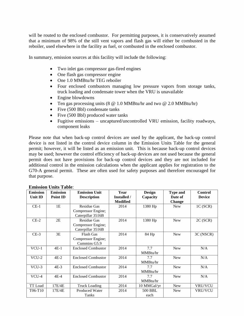
Emission Units Table: Emission
Unit ID
Emission
Point ID
Emission Unit
Description
Year
Installed /
Modified
Design
Capacity
Type and
Date of
Change
Control
Device
CE-1 1E Residue Gas
Compressor Engine;
Caterpillar 3516B
2014 1380 Hp New 1C (SCR)
CE-2 2E Residue Gas
Compressor Engine;
Caterpillar 3516B
2014 1380 Hp New 2C (SCR)
CE-3 3E Flash Gas
Compressor Engine;
Cummins G5.9
2014 84 Hp New 3C (NSCR)
VCU-1 4E-1 Enclosed Combustor 2014 7.7
MMBtu/hr
New N/A
VCU-2 4E-2 Enclosed Combustor 2014 7.7
MMBtu/hr
New N/A
VCU-3 4E-3 Enclosed Combustor 2014 7.7
MMBtu/hr
New N/A
VCU-4 4E-4 Enclosed Combustor 2014 7.7
MMBtu/hr
New N/A
TT Load 17E/4E Truck Loading 2014 10 MMGal/yr New VRU/VCU
T06-T10 17E/4E Produced Water
Tanks
2014 500 BBL
each
New VRU/VCU
T01-T05 17E/4E Condensate Tanks 2014 500 BBL
each
New VRU/VCU
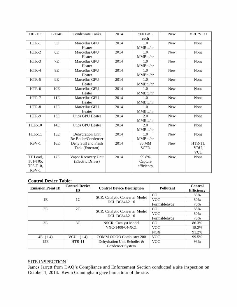
HTR-1 5E Marcellus GPU
Heater
2014 1.0
MMBtu/hr
New None
HTR-2 6E Marcellus GPU
Heater
2014 1.0
MMBtu/hr
New None
HTR-3 7E Marcellus GPU
Heater
2014 1.0
MMBtu/hr
New None
HTR-4 8E Marcellus GPU
Heater
2014 1.0
MMBtu/hr
New None
HTR-5 9E Marcellus GPU
Heater
2014 1.0
MMBtu/hr
New None
HTR-6 10E Marcellus GPU
Heater
2014 1.0
MMBtu/hr
New None
HTR-7 11E Marcellus GPU
Heater
2014 1.0
MMBtu/hr
New None
HTR-8 12E Marcellus GPU
Heater
2014 1.0
MMBtu/hr
New None
HTR-9 13E Utica GPU Heater 2014 2.0
MMBtu/hr
New None
HTR-10 14E Utica GPU Heater 2014 2.0
MMBtu/hr
New None
HTR-11 15E Dehydration Unit
Re-Boiler/Condenser
2014 1.0
MMBtu/hr
New None
RSV-1 16E Dehy Still and Flash
Tank (Exterran)
2014 80 MM
SCFD
New HTR-11,
VRU,
VCU
TT Load,
T01-T05,
T06-T10,
RSV-1
17E Vapor Recovery Unit
(Electric Driver)
2014 99.8%
Capture
efficiency
New None
Control Device Table:
Emission Point ID Control Device
ID Control Device Description Pollutant
Control
Efficiency
1E
1C SCR; Catalytic Converter Model
DCL DC64L2-16
CO 85%
VOC 80%
Formaldehyde 70%
2E 2C SCR; Catalytic Converter Model
DCL DC64L2-16
CO 85%
VOC 80%
Formaldehyde 70%
3E 3C NSCR; Catalyst Model
VXC-1408-04-XC1
CO 86.3%
VOC 18.2%
NOX 91.2%
4E- (1-4) VCU - (1-4) COMM OOOO Combuster 200 VOC 99.5%
15E HTR-11 Dehydration Unit Reboiler &
Condenser System
VOC 98%
SITE INSPECTION
James Jarrett from DAQ’s Compliance and Enforcement Section conducted a site inspection on
October 1, 2014. Kevin Cunningham gave him a tour of the site.
Directions to the facility are as follows: From Middlebourne, travel on WV-18 north for ~0.7
miles. Turn left onto Sellers Road (Rt. 2/4) for 0.1 miles then turn right onto Pleasants Ridge
Road (Rt. 18/4). Travel 2.3 miles and make a left on Goldring Road (Rt. 10/1). Google Earth
calls this road Allen Run Road. Travel 1.3 miles and make a right onto the site access road.
Travel ~0.5 miles to the site. UTM Coordinates505,185.95 m E & 4,373,341.60 m N.
Findings:
The closes residence is ~ 1,300 feet to the South from the well site.
The site commenced construction on August 6, 2014 but is not in operation. The Utica well is
ready for production. The 3 Marcellus wells need flowback completed. The gas from the Utica
well is expected to be dry and will not require compression. The gas from the Marcellus wells
are expected to be wet and will require compression.
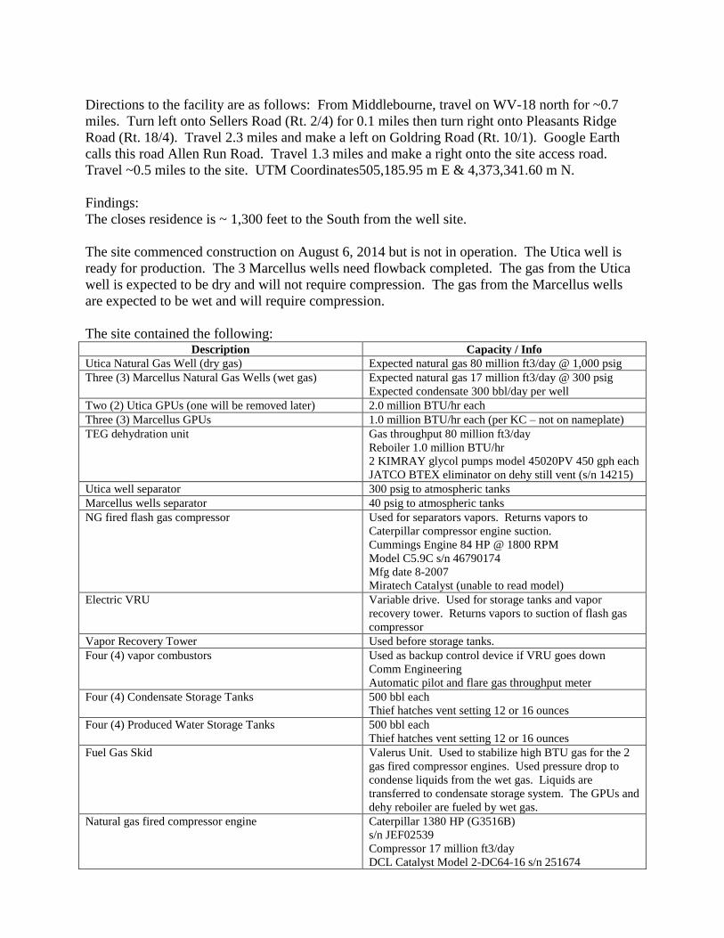
The site contained the following: Description Capacity / Info
Utica Natural Gas Well (dry gas) Expected natural gas 80 million ft3/day @ 1,000 psig
Three (3) Marcellus Natural Gas Wells (wet gas) Expected natural gas 17 million ft3/day @ 300 psig
Expected condensate 300 bbl/day per well
Two (2) Utica GPUs (one will be removed later) 2.0 million BTU/hr each
Three (3) Marcellus GPUs 1.0 million BTU/hr each (per KC – not on nameplate)
TEG dehydration unit Gas throughput 80 million ft3/day
Reboiler 1.0 million BTU/hr
2 KIMRAY glycol pumps model 45020PV 450 gph each
JATCO BTEX eliminator on dehy still vent (s/n 14215)
Utica well separator 300 psig to atmospheric tanks
Marcellus wells separator 40 psig to atmospheric tanks
NG fired flash gas compressor Used for separators vapors. Returns vapors to
Caterpillar compressor engine suction.
Cummings Engine 84 HP @ 1800 RPM
Model C5.9C s/n 46790174
Mfg date 8-2007
Miratech Catalyst (unable to read model)
Electric VRU Variable drive. Used for storage tanks and vapor
recovery tower. Returns vapors to suction of flash gas
compressor
Vapor Recovery Tower Used before storage tanks.
Four (4) vapor combustors Used as backup control device if VRU goes down
Comm Engineering
Automatic pilot and flare gas throughput meter
Four (4) Condensate Storage Tanks 500 bbl each
Thief hatches vent setting 12 or 16 ounces
Four (4) Produced Water Storage Tanks 500 bbl each
Thief hatches vent setting 12 or 16 ounces
Fuel Gas Skid Valerus Unit. Used to stabilize high BTU gas for the 2
gas fired compressor engines. Used pressure drop to
condense liquids from the wet gas. Liquids are
transferred to condensate storage system. The GPUs and
dehy reboiler are fueled by wet gas.
Natural gas fired compressor engine Caterpillar 1380 HP (G3516B)
s/n JEF02539
Compressor 17 million ft3/day
DCL Catalyst Model 2-DC64-16 s/n 251674
SOURCE AGGREGATION (as taken from the application)
Source aggregation determinations are typically made based on the following criteria:
Whether the facilities are under common control,
Whether the facilities belong to the same Major Group (i.e. the first two digit code) as
described in the Standard Industrial Classification Manual, 1972, as amended by the 1977
Supplement;
Whether the facilities are located on one or more contiguous or adjacent properties; and
the distance between all pollutant emitting activities,
Whether the facilities can operate independently.
Only if all criteria are met does a permitting authority aggregate the facilities into a single
source.
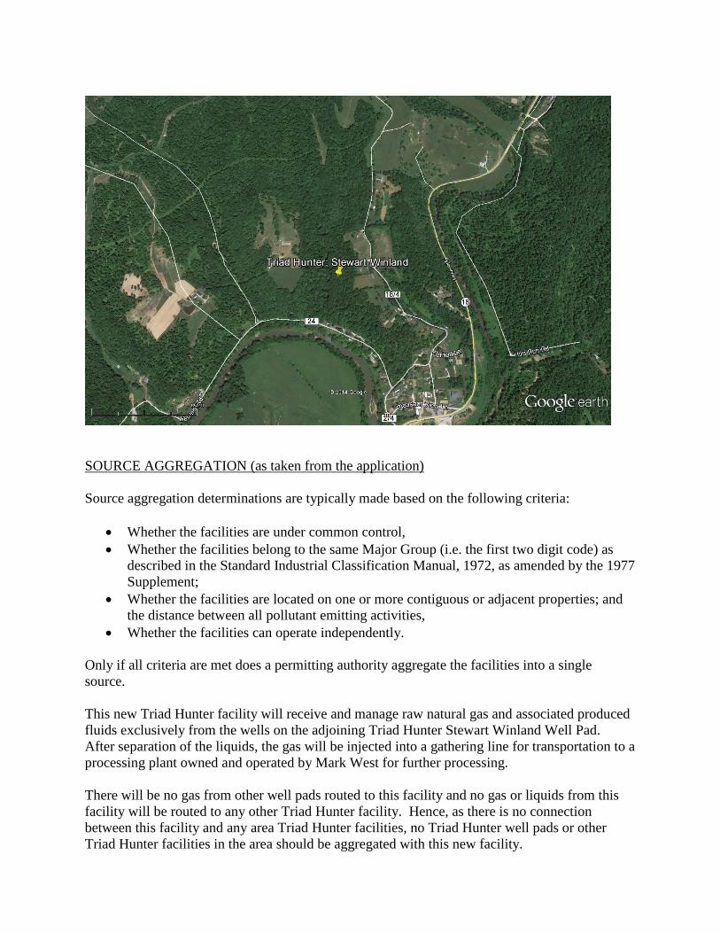
This new Triad Hunter facility will receive and manage raw natural gas and associated produced
fluids exclusively from the wells on the adjoining Triad Hunter Stewart Winland Well Pad.
After separation of the liquids, the gas will be injected into a gathering line for transportation to a
processing plant owned and operated by Mark West for further processing.
There will be no gas from other well pads routed to this facility and no gas or liquids from this
facility will be routed to any other Triad Hunter facility. Hence, as there is no connection
between this facility and any area Triad Hunter facilities, no Triad Hunter well pads or other
Triad Hunter facilities in the area should be aggregated with this new facility.
The receiving Mark West Mobley processing plant is under a different SIC Code, has completely
separate ownership and there is no sharing of staff between Triad Hunter and Mark West. In
addition, the processing plant is more than 15 miles from the site of this new facility. The Mark
West plant receives gas from various other production facilities and is not dependent upon
Stewart Winland. Additionally, Triad Hunter can, within the confines of any contractual
obligations, route gas produced by Stewart Winland to any of several other processing plants in
the region. Thus, there is not a dependency relationship and not all of the criteria are met for
aggregation of this new facility and the Mark West Mobley Processing Plant. Emissions from
the Stewart Winland Production Facility should not be aggregated with the Mark West
Processing Plant.
ESTIMATE OF EMISSIONS BY REVIEWING ENGINEER
Engines
Engine Emissions [CE-1 and CE-2] were calculated based on manufacturer’s emission factors
for NOX, CO, VOC, Formaldehyde, and CO2e emissions and AP-42 emission factors for PM and
SO2. A catalytic converter (SCR) is used to reduce the CO, VOC, and Formaldehyde emissions
and an air/fuel ratio control is used for NOX feedback.
Engine Emissions [CE-3] were calculated based on manufacturer’s emission factors for NOX,
CO, VOC, and Formaldehyde. AP-42 emission factors were used for PM2.5 and SO2. The
40CFR98, Table C-2 emission factor was used for CH4. A catalytic converter (NSCR) is used to
reduce the CO, NOX, and VOC emissions.
GPUs
The emissions from the heaters [HTR-1 through HTR-10] and the emissions from the
dehydration unit reboiler [HTR-11] were calculated using AP-42 emission factors, Chapter 1.4.
Dehydration Unit
Emissions from the Still Vent [16E] and Reboiler [15E] were calculated using GRI-GLYCalc,
Version 4.0. The emissions from the dehydration unit are controlled with a condenser and
reboiler (combustion device). A destruction efficiency of 98% was used for the combustion
device in the calculations. The reboiler emissions were calculated using AP-42 emission factors.
Tank Truck Loading
Estimates of potential VOC emissions from tank truck loading of condensate and water were
calculated using AP-42 methodology with VOC content calculated from ProMax modeling.
Tank truck loading emissions are routed to the VRU/VCU.
The loading loss factor for condensate is 7.99 lbs/1000 gallons loaded. The ProMax model
estimated that the condensate emissions are 95.1 % VOCs. The maximum throughputs for
condensate loading are 54,200 gallons/day (all loading takes place within 12 hours) and
4,300,000 gallons/yr.
The condensate calculations provided by the applicant included a capture efficiency of 99.2%
allowed by AP-42 for annual MACT testing of the tank trucks.
The loading loss factor for water is 0.15 lb/1000 gallons loaded. The maximum throughputs for
water loading are 37,900 gallons/day (all loading takes place within 12 hours) and 3,024,000
gallons/yr. The capture efficiency used in the calculations was 70% for un-tested water trucks.
Storage Tanks
The condensate is routed through a condensate flash separator and a condensate tower prior to
being routed to the condensate storage tanks. Emissions from the Condensate Tanks were
calculated using API E&P Tanks that include flash emissions and were included in the ProMax
simulation model. VOC emission calculations for the produced water tanks are based on a mass
balance calculation using ProMax simulation model. The models were reviewed and the
uncontrolled emissions were verified. A single VRU will receive and re-compress vapors from
the condensate and produced water storage tanks at the Stewart Windland Well Pad Production
Facility.
Both the Condensate and the Produced Water tanks are included in the ProMax simulation model
that is used to provide the emissions that are emitted through the VRU/VCU emission points;
therefore there are no specific emission limits for the storage vessels. The VRU/VCU emissions
included vapors not only from the storage tanks but also from other streams in the overall
process.
The total condensate throughput of all tanks is 4,300,000 gal/yr and the total produced water
throughput of all tanks is 3,024,000 gal/yr.
Vapor Recovery Unit (VRU)
The applicant claimed 99.8% capture and control efficiency and states in the application that
Triad Hunter will be installing the necessary controls and implement the necessary
recordkeeping to make this claim. The VOC emissions associated with the VRU will be
comprised of the 0.2% of the vapors that are not captured and controlled. The driver for the
VRU device is electric and therefore there are no associated engine emissions.
WVDAQ follows the guidance provided by TCEQ for applicants that claim capture/control
efficiency greater than 95% for their VRU System.
The VRU capture and control efficiency claim of 99.8% is based upon the following features of
the VRU:
In addition to sensing equipment that will trigger the VRU to turn on when the pressure
within the condensate tanks reach a minimum pressure, sensing equipment will also be
installed to monitor the run status of the VRU. If the VRU shuts down, the vapors will
automatically be routed to an enclosed combustor with a destruction efficiency warranted
at 99.8%.
There will be a recycle loop in the VRU system whereby discharge from the VRU will be
routed back to the VRU inlet until appropriate pressure is built up for the compressor to
be turned on, eliminating the possibility of a vacuum being pulled on the tank.
Triad will run both a blanket gas and have automatic throttling to ensure oxygen does not
enter the tanks.
The VRU is capable of varying operating speed of the compressor to respond to
conditions for varying environmental and operating conditions.
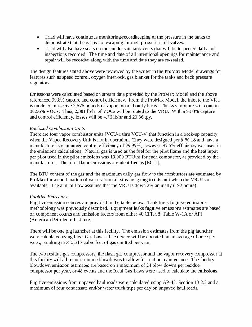
Triad will have continuous monitoring/recordkeeping of the pressure in the tanks to
demonstrate that the gas is not escaping through pressure relief valves.
Triad will also have seals on the condensate tank vents that will be inspected daily and
inspections recorded. The time and date of all intentional openings for maintenance and
repair will be recorded along with the time and date they are re-sealed.
The design features stated above were reviewed by the writer in the ProMax Model drawings for
features such as speed control, oxygen interlock, gas blanket for the tanks and back pressure
regulators.
Emissions were calculated based on stream data provided by the ProMax Model and the above
referenced 99.8% capture and control efficiency. From the ProMax Model, the inlet to the VRU
is modeled to receive 2,676 pounds of vapors on an hourly basis. This gas mixture will contain
88.96% VOCs. Thus, 2,381 lb/hr of VOCs will be routed to the VRU. With a 99.8% capture
and control efficiency, losses will be 4.76 lb/hr and 20.86 tpy.
Enclosed Combustion Units
There are four vapor combustor units [VCU-1 thru VCU-4] that function in a back-up capacity
when the Vapor Recovery Unit is not in operation. They were designed per § 60.18 and have a
manufacturer’s guaranteed control efficiency of 99.99%; however, 99.5% efficiency was used in
the emissions calculations. Natural gas is used as the fuel for the pilot flame and the heat input
per pilot used in the pilot emissions was 19,000 BTU/hr for each combustor, as provided by the
manufacturer. The pilot flame emissions are identified as [EC-1].
The BTU content of the gas and the maximum daily gas flow to the combustors are estimated by
ProMax for a combination of vapors from all streams going to this unit when the VRU is un-
available. The annual flow assumes that the VRU is down 2% annually (192 hours).
Fugitive Emissions
Fugitive emission sources are provided in the table below. Tank truck fugitive emissions
methodology was previously described. Equipment leaks fugitive emissions estimates are based
on component counts and emission factors from either 40 CFR 98, Table W-1A or API
(American Petroleum Institute).
There will be one pig launcher at this facility. The emission estimates from the pig launcher
were calculated using Ideal Gas Laws. The device will be operated on an average of once per
week, resulting in 312,317 cubic feet of gas emitted per year.
The two residue gas compressors, the flash gas compressor and the vapor recovery compressor at
this facility will all require routine blowdowns to allow for routine maintenance. The facility
blowdown emission estimates are based on a maximum of 24 blow downs per residue
compressor per year, or 48 events and the Ideal Gas Laws were used to calculate the emissions.
Fugitive emissions from unpaved haul roads were calculated using AP-42, Section 13.2.2 and a
maximum of four condensate and/or water truck trips per day on unpaved haul roads.
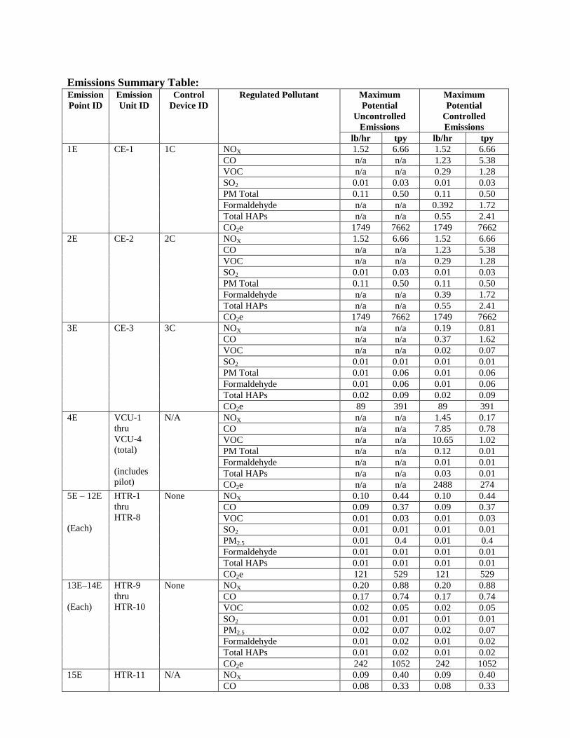
Emissions Summary Table: Emission
Point ID
Emission
Unit ID
Control
Device ID
Regulated Pollutant Maximum
Potential
Uncontrolled
Emissions
Maximum
Potential
Controlled
Emissions
lb/hr tpy lb/hr tpy
1E CE-1 1C NOX 1.52 6.66 1.52 6.66
CO n/a n/a 1.23 5.38
VOC n/a n/a 0.29 1.28
SO2 0.01 0.03 0.01 0.03
PM Total 0.11 0.50 0.11 0.50
Formaldehyde n/a n/a 0.392 1.72
Total HAPs n/a n/a 0.55 2.41
CO2e 1749 7662 1749 7662
2E CE-2 2C NOX 1.52 6.66 1.52 6.66
CO n/a n/a 1.23 5.38
VOC n/a n/a 0.29 1.28
SO2 0.01 0.03 0.01 0.03
PM Total 0.11 0.50 0.11 0.50
Formaldehyde n/a n/a 0.39 1.72
Total HAPs n/a n/a 0.55 2.41
CO2e 1749 7662 1749 7662
3E CE-3 3C NOX n/a n/a 0.19 0.81
CO n/a n/a 0.37 1.62
VOC n/a n/a 0.02 0.07
SO2 0.01 0.01 0.01 0.01
PM Total 0.01 0.06 0.01 0.06
Formaldehyde 0.01 0.06 0.01 0.06
Total HAPs 0.02 0.09 0.02 0.09
CO2e 89 391 89 391
4E VCU-1
thru
VCU-4
(total)
(includes
pilot)
N/A NOX n/a n/a 1.45 0.17
CO n/a n/a 7.85 0.78
VOC n/a n/a 10.65 1.02
PM Total n/a n/a 0.12 0.01
Formaldehyde n/a n/a 0.01 0.01
Total HAPs n/a n/a 0.03 0.01
CO2e n/a n/a 2488 274
5E – 12E
(Each)
HTR-1
thru
HTR-8
None NOX 0.10 0.44 0.10 0.44
CO 0.09 0.37 0.09 0.37
VOC 0.01 0.03 0.01 0.03
SO2 0.01 0.01 0.01 0.01
PM2.5 0.01 0.4 0.01 0.4
Formaldehyde 0.01 0.01 0.01 0.01
Total HAPs 0.01 0.01 0.01 0.01
CO2e 121 529 121 529
13E–14E
(Each)
HTR-9
thru
HTR-10
None NOX 0.20 0.88 0.20 0.88
CO 0.17 0.74 0.17 0.74
VOC 0.02 0.05 0.02 0.05
SO2 0.01 0.01 0.01 0.01
PM2.5 0.02 0.07 0.02 0.07
Formaldehyde 0.01 0.02 0.01 0.02
Total HAPs 0.01 0.02 0.01 0.02
CO2e 242 1052 242 1052
15E HTR-11 N/A NOX 0.09 0.40 0.09 0.40
CO 0.08 0.33 0.08 0.33
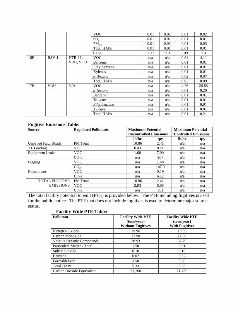
VOC 0.01 0.02 0.01 0.02
SO2 0.01 0.01 0.01 0.01
PM2.5 0.01 0.03 0.01 0.03
Total HAPs 0.01 0.01 0.01 0.01
CO2e 109 501 109 501
16E RSV-1
HTR-11,
VRU, VCU
VOC n/a n/a 0.94 4.11
Benzene n/a n/a 0.01 0.01
Ethylbenzene n/a n/a 0.01 0.01
Xylenes n/a n/a 0.01 0.01
n-Hexane n/a n/a 0.02 0.07
Total HAPs n/a n/a 0.02 0.09
17E VRU
N/A VOC n/a n/a 4.76 20.85
n-Hexane n/a n/a 0.01 0.20
Benzene n/a n/a 0.01 0.01
Toluene n/a n/a 0.01 0.01
Ethylbenzene n/a n/a 0.01 0.01
Xylenes n/a n/a 0.01 0.01
Total HAPs n/a n/a 0.01 0.21
Fugitive Emissions Table: Source Regulated Pollutants Maximum Potential
Uncontrolled Emissions
Maximum Potential
Controlled Emissions
lb/hr tpy lb/hr tpy
Unpaved Haul Roads PM Total 10.86 2.41 n/a n/a
TT Loading VOC 0.43 0.21 n/a n/a
Equipment Leaks VOC 1.60 7.00 n/a n/a
CO2e n/a 207 n/a n/a
Pigging VOC n/a 1.48 n/a n/a
CO2e n/a 147.9 n/a n/a
Blowdowns VOC n/a 0.19 n/a n/a
CO2e n/a 6.12 n/a n/a
TOTAL FUGITIVE
EMISSIONS
PM Total 10.86 2.41 n/a n/a
VOC 2.03 8.88 n/a n/a
CO2e n/a 361 n/a n/a
The total facility potential to emit (PTE) is provided below. The PTE including fugitives is used
for the public notice. The PTE that does not include fugitives is used to determine major source
status.
Facility Wide PTE Table: Pollutant Facility Wide PTE
(tons/year)
Without Fugitives
Facility Wide PTE
(tons/year)
With Fugitives
Nitrogen Oxides 19.96 19.96
Carbon Monoxide 17.90 17.90
Volatile Organic Compounds 28.93 37.79
Particulate Matter - Total 1.50 3.91
Sulfur Dioxide 0.10 0.10
Benzene 0.02 0.02
Formaldehyde 3.50 3.50
Total HAPs 5.33 5.33
Carbon Dioxide Equivalent 21,760 21,760
REGULATORY APPLICABILITY
The following state and federal regulations were reviewed for applicability.
State Regulations:
45CSR2 (Particulate Air Pollution from Combustion of Fuel in Indirect Heat Exchangers)
The purpose of 45CSR2 is to establish emission limitations for smoke and particulate
matter which are discharged from fuel burning units. 45CSR2 states that any fuel
burning unit that has a heat input under ten (10) million B.T.U.'s per hour is exempt from
sections 4 (weight emission standard), 5 (control of fugitive particulate matter), 6
(registration), 8 (testing, monitoring, recordkeeping, reporting) and 9 (startups,
shutdowns, malfunctions). However, failure to attain acceptable air quality in parts of
some urban areas may require the mandatory control of these sources at a later date.
The individual heat input of the GPU Heaters (HTR-1 thru HTR-10) and the Dehydration
Unit Reboiler (HTR-11) are below 10 MMBTU/hr. Therefore, these units are exempt
from the aforementioned sections of 45CSR2.
The applicant is subject to the opacity requirements in 45CSR2, which is 10% opacity
based on a six minute block average.
45CSR6 (To Prevent and Control Air Pollution from the Combustion of Refuse)
45CSR6 prohibits open burning, establishes emission limitations for particulate matter,
and establishes opacity requirements. Sources subject to 45CSR6 include completion
combustion devices, enclosed combustion devices, and flares.
The facility-wide requirements of the permit include the open burning limitations §§45-
6-3.1 and 3.2.
All completion combustion devices, enclosed combustion devices, and flares are subject
to the particulate matter weight emission standard set forth in §45-6-4.1; the opacity
requirements in §§45-6-4-3 and 4-4; the visible emission standard in §45-6-4.5; the odor
standard in §45-6-4.6; and the testing standard in §§45-6-7.1 and 7.2.
Flares that are used to comply with emission standards of NSPS, Subpart OOOO are
subject to design, operational, performance, recordkeeping and reporting requirements of
the NSPS regulation that meet or exceed the requirements of 45CSR6.
The applicant has four (4) vapor combustor units that will be used as back-up devices to
the VRU system. The vapor combustors have negligible particulate matter emissions.
Therefore, the facility’s vapor combustor units should demonstrate compliance with this
section. The facility will demonstrate compliance by maintaining records of the amount
of natural gas consumed by the flare and the hours of operation. The facility will also
monitor the flame of the flare and record any malfunctions that may cause no flame
to be present during operation.
45CSR10 (To Prevent and Control Air Pollution from the Emissions of Sulfur Oxides)
The purpose of 45CSR10 is to establish emission limitations for sulfur dioxide which are
discharged from fuel burning units. 45CSR10 states that any fuel burning unit that has a
heat input under ten (10) million B.T.U.'s per hour is exempt from sections 3 (weight
emission standard), 6 (registration), 7 (permits), and 8 (testing, monitoring,
recordkeeping, reporting). However, failure to attain acceptable air quality in parts of
some urban areas may require the mandatory control of these sources at a later date.
The individual heat input of the GPU Heater (HTR-1 thru HTR-10) and the Dehydration
Unit Reboiler (HTR-11) are below 10 MMBTU/hr. Therefore, these units are exempt
from the aforementioned sections of 45CSR10.
45CSR13 (Permits for Construction, Modification, Relocation and Operation of Stationary
Sources of Air Pollutants, Notification Requirements, Administrative Updates, Temporary
Permits, General Permits, and Procedures for Evaluation)
Potential emissions associated with the proposed project are greater than the minor source
construction permit thresholds of 6 pounds per hour (pph) and 10 tons per year (tpy) of
any regulated air pollutant of 144 pounds per day (ppd) of any regulated air pollutant OR
2 pph OR 5 tpy of aggregated hazardous air pollutants OR 45 CSR27 toxic air pollutant
OR subject to applicable substantive rule. The applicant has demonstrated compliance
with 45CSR13 by submitting a complete permit application.
Triad Hunter has published the required Class I legal advertisement notifying the public
of their permit application, and paid the appropriate application fees. The Class I legal
advertisement ran in the Tyler Star News, on October 8, 2014.
45CSR16 (Standards of Performance for New Stationary Sources Pursuant to 40 CFR Part 60)
45CSR16 applies to this source by reference of 40CFR60, Subparts JJJJ and OOOO.
These requirements are discussed under that rule below.
45CSR22 (Air Quality Management Fee Program)
This facility will be required to maintain a valid Certificate to Operate on the premises.
45CSR34 (Emission Standards for Hazardous Air Pollutants)
45CSR34 applies to any applicant that is subject to the area source requirements of 40
CFR 63, Subpart ZZZZ or Subpart HH, described in more detail in the Federal
Regulations section. WVDAQ has taken delegation of the area source requirements of
these subparts. 45CSR34 applies to this applicant because they are subject to the
applicable requirements of NESHAP, Subpart HH and ZZZZ.
Federal Regulations:
40CFR60, Subpart JJJJ (Standards of Performance for Stationary Spark Ignition Internal
Combustion Engines)
This subpart governs emissions from new stationary spark ignition internal combustion
engines (SI ICE) manufactured after July 1, 2007. Both natural gas compressor engines
(CE-1 and CE-2) and the Flash Gas Compressor engine (CE-3) presented in this
application will be SI ICE units manufactured after this date. Engines CE-1 and CE-2
were manufactured after January 1, 2010. Engine CE-3 has a manufactured date of
August 1, 2007. Accordingly, this rule applies to those engines. The application states
that all engines installed will be in compliance with the requirements of this rule.
The engine data sheets provided in the application state that the engines are not certified
engines according to NSPS, Subpart JJJJ.
Compliance will be determined by compliance to permit requirements.
40CFR60 Subpart OOOO (Standards of Performance for Crude Oil and Natural Gas
Production, Transmission and Distribution)
EPA published in the Federal Register new source performance standards (NSPS) and air
toxics rules for the oil and gas sector on August 16, 2012. 40CFR60 Subpart OOOO
establishes emission standards and compliance schedules for the control of volatile
organic compounds (VOC) and sulfur dioxide (SO2) emissions from affected facilities
that commence construction, modification or reconstruction after August 23, 2011. The
following affected sources which commence construction, modification or reconstruction
after August 23, 2011 are subject to the applicable provisions of this subpart:
a. Each gas well affected facility, which is a single natural gas well.
The applicant has four (4) natural gas well affected facilities. The API numbers
for the wells at this facility are: 47-9502128, 47-9502089, 47-9502088, and 47-
9502087.
The gas wells at the Stewart Winland Pad are being drilled principally for the
production of natural gas and were done so after August 23, 2011. Therefore,
these wells would be considered affected facilities under this subpart. The
compliance date for these hydraulically fractured wells is October 15, 2012.
Triad Hunter is required under §60.5410 to submit an initial notification, initial
annual report, maintain a log of records for each well completion, and maintain
records of location and method of compliance. §60.5420 requires the applicant to
demonstrate continuous compliance by submitting reports and maintaining
records for each completion operation.
b. Each reciprocating compressor affected facility, which is a single reciprocating
compressor located between the wellhead and the point of custody transfer to the
natural gas transmission and storage segment. For the purposes of this subpart,
your reciprocating compressor is considered to have commenced construction on
the date the compressor is installed (excluding relocation) at the facility. A
reciprocating compressor located at a well site, or an adjacent well site and
servicing more than one well site, is not an affected facility under this subpart.
There are reciprocating internal combustion engines included in the Stewart
Winland application. The engines will be delivered after the effective date of this
rule. However, §60.5365(c) states that a reciprocating compressor located at a
well site, or an adjacent well site and servicing more than one well site, is not an
affected facility under this subpart. Therefore, all requirements regarding
reciprocating compressors under 40 CFR 60 Subpart OOOO would not apply.
c. Pneumatic Controllers
Each pneumatic controller affected facility, which is a single continuous bleed
natural gas-driven pneumatic controller operating at a natural gas bleed rate
greater than 6 scfh which commenced construction after August 23, 2011, and is
located between the wellhead and the point of custody transfer to the natural gas
transmission and storage segment and not located at a natural gas processing
plant.
Each pneumatic controller affected facility, which is a single continuous bleed
natural gas-driven pneumatic controller which commenced construction after
August 23, 2011, and is located at a natural gas processing plant.
According to the regulatory section of the permit application, all pneumatic
controllers to be installed at Stewart Winland Production Facility will have a
bleed rate of less than 6 scfh.
d. Each storage vessel affected facility, which is a single storage vessel, located in
the oil and natural gas production segment, natural gas processing segment or
natural gas transmission and storage segment.
40CFR60 Subpart OOOO defines a storage vessel as a unit that is constructed
primarily of non-earthen materials (such as wood, concrete, steel, fiberglass, or
plastic) which provides structural support and is designed to contain an
accumulation of liquids or other materials. The following are not considered
storage vessels:
Vessels that are skid-mounted or permanently attached to something that
is mobile (such as trucks, railcars, barges or ships), and are intended to be
located at a site for less than 180 consecutive days. If the source does not
keep or are not able to produce records, as required by §60.5420(c)(5)(iv),
showing that the vessel has been located at a site for less than 180
consecutive days, the vessel described herein is considered to be a storage
vessel since the original vessel was first located at the site.
Process vessels such as surge control vessels, bottoms receivers or
knockout vessels.
Pressure vessels designed to operate in excess of 204.9 kilopascals and
without emissions to the atmosphere.
This rule requires that the permittee determine the VOC emission rate for each storage
vessel affected facility utilizing a generally accepted model or calculation methodology
within 30 days of startup, and minimize emissions to the extent practicable during the 30
day period using good engineering practices. For each storage vessel affected facility
that emits more than 6 tpy of VOC, the permittee must reduce VOC emissions by 95% or
greater within 60 days of startup. The compliance date for applicable storage vessels is
October 15, 2013.
The storage vessels at this facility were constructed after August 23, 2011. The facility is
considered to have Group 1 Storage Vessels.
At the time of the application, the facility has determined the uncontrolled emissions
from the storage tanks are greater than 6 tpy from each condensate vessel. The emissions
from the storage vessels at the Stewart Winland facility will be routed to a vapor recover
unit with a 99.5% capture/control efficiency that includes vapor combustors as back-up to
the VRU system. The potential emissions that will be included in the permit will be less
than 6 tpy of VOC. Therefore, Triad Hunter is not required by this section to further
reduce VOC emissions by 95%, since this subpart takes into account federal enforceable
controls.
40CFR63, Subpart HH (National Emission Standards for Hazardous Air Pollutants for Source
Categories from Oil and Natural Gas Production Facilities)
The proposed equipment for the Stewart Winland Production Facility does contain a TEG
dehydration operation; therefore, this rule applies. However, as set forth in 40 CFR
63.764(d)(2), since the actual average benzene emissions will be less than 1 tpy, the
facility is, for all practical purposes, exempt from the rule. The facility must maintain
records of this determination as required in 40 CFR63.774(d)(1). A copy of the GRI-
GLYCALC modeling input and results demonstrating compliance with the 1 tpy
requirements is provided in the emissions calculations provided in the application.
The applicant has demonstrated eligibility for the exemption on the basis of the RSV-1
benzene PTE emissions.
40CFR63, Subpart ZZZZ (National Emission Standards for Hazardous Air Pollutants for
Source Categories from Stationary Reciprocating Internal Combustion Engines – Area Source)
This subpart governs emissions from a stationary reciprocating internal combustion
engine (RICE) located at both major and area sources of HAPs. The facility will be an
area source of HAPs and is subject to this rule. All of the engines that will be installed
under this application will be manufactured after July 1, 2010.
In accordance with 40 CFR63.6590(a)(2)(iii), none of the engines at the planned Stewart
Winland Production facility will be considered existing stationary RICE. All will be
considered “new” engines. Therefore, the engines will meet the requirements of this rule
by meeting the requirements of NSPS, Subpart JJJJ as described above.
The applicant will be demonstrating compliance with Subpart ZZZZ by demonstrating
compliance with Subpart JJJJ for new engines.
Non-applicability determinations
45CSR14 (Permits for Construction and Major Modification of Major Stationary Sources for the
Prevention of Significant Deterioration of Air Quality)
“Major stationary source” is any stationary source (not including the named source type
in 2.43.a) which emits or has the potential to emit, two hundred fifty (250) tons per year
or more of any regulated pollutant. For this facility, the fugitives are not included in
determining “major stationary source” status.
With the additional level of capture/control of the VRU system allowed by the R13-3214
permit with appropriate federally enforceable limitations and requirements, the applicant
has VOC potential emissions below the major stationary source threshold for PSD when
the permit is issued.
45CSR30 (Requirements for Operating Permits)
“Major source” means any stationary source (or any group of stationary sources that are
located on one or more contiguous or adjacent properties, and are under common control
of the same person (or persons under common control)) belonging to a single major
industrial grouping and that is described in subdivisions 2.26.a, 2.26.b, or 2.26.c. For the
purpose of defining “major source,” a stationary source or group of stationary sources
shall be considered part of a single industrial grouping if all of the pollutant emitting
activities at such source or group of sources on contiguous or adjacent properties belong
to same Major Group (i.e., all have the same two-digit code) as described in the Standard
Industrial Classification Manual, 1987,
except that a research and development facility may be treated as a separate source from
other stationary sources that are part of the same industrial grouping, are located on
contiguous or adjacent property, and are under common control.
(2.26.a) Any stationary source that emits or has the potential to emit, in the aggregate, ten
(10) tons per year (tpy) or more of any hazardous air pollutant, or twenty-five (25) tpy or
more of any combination of hazardous air pollutants.
(2.26.b) Directly emits or has the potential to emit, one hundred (100) tpy or more of any
air pollutant subject to regulation. The fugitive emissions for this stationary source are
not included in the determination of major source status because it does not belong to one
of the named source categories.
With the additional level of capture/control of the VRU system allowed by the R13-3214
permit with appropriate federally enforceable limitations and requirements, the applicant
will have VOC potential emissions below the major source threshold for Title V when the
permit is issued.
NSPS, Subpart Kb (Volatile Organic Liquid Storage Tanks constructed or modified after
1984)
The capacity of these tanks (21,000 gallons or 500 BBL) is above the threshold for this
regulation (19,800 gallons or 75 cubic meters). However, in accordance with 40
CFR60.110b(d)(4), “Vessels with a design capacity less than or equal to 1,589.874 m3
(420,000 gallons) used for petroleum or condensate stored, processed, or treated prior to
custody transfer” are excluded from regulation. Hence, the rule does not apply to the
four stabilized condensate tanks.
TOXICITY OF NON-CRITERIA REGULATED POLLUTANTS
Non-criteria regulated hazardous air pollutants such as benzene, toluene, and formaldehyde may
be emitted when natural gas is combusted in reciprocating engines, combusted in the fuel
burning units, or combusted in one of the combustion type air pollution control devices.
Listed below is information regarding each of the hazardous air pollutants.
BTEX:
BTEX is the term used for benzene, toluene, ethylbenzene, and xylene. Each of these possible
hazardous air pollutants are identified in this section.
Benzene: Benzene is found in the air from emissions from burning coal and oil, gasoline service stations,
and motor vehicle exhaust. Acute (short-term) inhalation exposure of humans to benzene may
cause drowsiness, dizziness, headaches, as well as eye, skin, and respiratory tract irritation, and,
at high levels, unconsciousness. Chronic (long-term) inhalation exposure has caused various
disorders in the blood, including reduced numbers of red blood cells and aplastic anemia, in
occupational settings. Reproductive effects have been reported for women exposed by inhalation
to high levels, and adverse effects on the developing fetus have been observed in animal tests.
Increased incidence of leukemia (cancer of the tissues that form white blood cells) have been
observed in humans occupationally exposed to benzene. EPA has classified benzene as a Group
A, human carcinogen.
Ethyl Benzene:
Ethyl benzene is mainly used in the manufacturing of styrene. Acute (short-term) exposure to
ethyl benzene in humans results in respiratory effects, such as throat irritation and chest
constriction, irritation of the eyes, and neurological effects, such as dizziness. Chronic (long-
term) exposure to ethyl benzene by inhalation in humans has shown conflicting results regarding
its effects on the blood. Animal studies have reported effects on the blood, liver, and kidneys
from chronic inhalation exposure to ethyl benzene. Limited information is available on the
carcinogenic effects of ethyl benzene in humans. In a study by the National Toxicology Program
(NTP), exposure to ethyl benzene by inhalation resulted in an increased incidence of kidney and
testicular tumors in rats, and lung and liver tumors in mice. EPA has classified ethyl benzene as a
Group D, not classifiable as to human carcinogenicity.
Formaldehyde: Formaldehyde is used mainly to produce resins used in particle board products and as an
intermediate in the synthesis of other chemicals. Exposure to formaldehyde may occur by
breathing contaminated indoor air, tobacco smoke, or ambient urban air. Acute (short-term) and
chronic (long-term) inhalation exposure to formaldehyde in humans can result in respiratory
symptoms, and eye, nose, and throat irritation. Limited human studies have reported an
association between formaldehyde exposure and lung and nasopharyngeal cancer. Animal
inhalation studies have reported an increased incidence of nasal squamous cell cancer. EPA
considers formaldehyde a probable human carcinogen (Group B1).
n-Hexane:
n-Hexane is a solvent that has many uses in the chemical and food industries, either in pure form
or as a component of commercial hexane. The latter is a mixture that contains approximately
52% n-hexane; the balance is made up of structural analogs and related chemicals such as
methylpentane and methylcyclopentane. Highly purified n-hexane is used as a reagent for
chemical or chromatographic separations. Other grades of n-hexane are used as solvents for
extracting edible fats and oils in the food industry and as a cleaning agent in the textile, furniture,
and printing manufacturing industries. Hexane is the solvent base for many commercial products,
such as glues, cements, paint thinners, and degreasers. n-Hexane is a minor constituent of crude
oil and natural gas and occurs in different petroleum distillates. No data are available regarding
the potential toxicity of n-hexane in humans orally exposed to n-hexane. However, as might be
expected for a chemical with such wide application, the potential exists for persons to be
environmentally and/or occupationally exposed to n-hexane via other routes of exposure.
Toluene:
The acute toxicity of toluene is low. Toluene may cause eye, skin, and respiratory tract irritation.
Short-term exposure to high concentrations of toluene (e.g., 600 ppm) may produce fatigue,
dizziness, headaches, loss of coordination, nausea, and stupor; 10,000 ppm may cause death from
respiratory failure. Ingestion of toluene may cause nausea and vomiting and central nervous
system depression. `Contact of liquid toluene with the eyes causes temporary irritation. Toluene
is a skin irritant and may cause redness and pain when trapped beneath clothing or shoes;
prolonged or repeated contact with toluene may result in dry and cracked skin. Because of its
odor and irritant effects, toluene is regarded as having good warning properties. The chronic
effects of exposure to toluene are much less severe than those of benzene. No carcinogenic
effects were reported in animal studies. Equivocal results were obtained in studies to determine
developmental effects in animals. Toluene was not observed to be mutagenic in standard studies.
Xylene:
Commercial or mixed xylene usually contains about 40-65% m-xylene and up to 20% each of o-
xylene and p-xylene and ethyl benzene. Xylenes are released into the atmosphere as fugitive
emissions from industrial sources, from auto exhaust, and through volatilization from their use as
solvents. Acute (short-term) inhalation exposure to mixed xylenes in humans results in irritation
of the eyes, nose, and throat, gastrointestinal effects, eye irritation, and neurological effects.
Chronic (long-term) inhalation exposure of humans to mixed xylenes results primarily in central
nervous system (CNS) effects, such as headache, dizziness, fatigue, tremors, and incoordination;
respiratory, cardiovascular, and kidney effects have also been reported. EPA has classified mixed
xylenes as a Group D, not classifiable as to human carcinogenicity. Mixed xylenes are used in
the production of ethylbenzene, as solvents in products such as paints and coatings, and are
blended into gasoline.
AIR QUALITY IMPACT ANALYSIS
Modeling was not required of this source due to the fact that the facility is not subject to
45CSR14 (Permits for Construction and Major Modification of Major Stationary Sources of Air
Pollutants) as seen in the table listed in the Regulatory Discussion Section.
MONITORING OF OPERATIONS
Natural Gas Wells
Per NSPS, Subpart OOOO
Pneumatic Controllers
Per NSPS, Subpart OOOO
Engines
Catalytic Oxidizer Control Devices regularly inspected to maintain proper operation of the
A/F ratio controller or automatic feedback controller and follow catalyst manufacturers
maintenance procedures
Records for hours of operation, fuel consumption, maintenance, catalyst maintenance,
engine maintenance plan
Per NSPS, Subpart JJJJ
GPU Heaters and Glycol Dehydration Unit Reboiler
Opacity monitoring upon request
Records of natural gas consumption
Storage Tanks
Daily inspection of condensate tank seals (per application) & records
Closed vent system monitoring (initial & continuous) & records
Throughput records (monthly & annual)
Records of affected facility determination after start-up
Reporting if condensate tower plans to be removed from service
VRU System
Throughput to the VRU and the VCUs monitored on a monthly basis & records
VRU monitored per manufacturer’s recommendations
Closed vent system monitoring (initial & continuous) & records
Continuous monitoring/recordkeeping of the pressure in the tanks to demonstrate that the
gas is not escaping through pressure relief valves & records
Continuous monitoring of VRU run status
Records of VRU design, downtime
Maintenance records
Vapor Combustor Units
VCU design records
Monitor presence of pilot flame with flame ionization detector & records when absent
VE monitoring & records
Maintenance records
Tank Truck Loading
Records of annual MACT leak test certification for every condensate TT loaded
Throughput records (monthly, annual)
Glycol Dehydration Unit
Monitor throughput of wet natural gas monthly & records
Wet gas sample upon request
Per NESHAP, Subpart HH for units exempt to § 63.764(d)
RECOMMENDATION TO DIRECTOR
It is recommended that permit R13-3214 be granted to the Triad Hunter, LLC, Stewart Winland
Production Facility (095-00042) located in Middlebourne, Tyler County, WV. Based on the
information provided in the application, including all supplemental information received, the
applicant will meet all state and federal regulations by demonstrating compliance to the permit
requirements.
Laura Jennings
Permit Engineer
Date