Embed Size (px)
Citation preview
W.E.ST. Elektronik GmbH
Technical Documentation
POS-123-A-PDP
POS-123-I-PDP
Universal positioning module with Profibus DP and SSI interface
W.E.ST. Elektronik GmbH
Page 2 of 37 POS-123-*-PDP-1115 04.09.2014
CONTENTS
1 General Information....................................................................................................................................... 4 1.1 Order number ......................................................................................................................................... 4 1.2 Scope of supply ...................................................................................................................................... 4 1.3 Accessories ............................................................................................................................................ 4 1.4 Symbols used ......................................................................................................................................... 5 1.5 Legal notice ............................................................................................................................................ 5 1.6 Safety instructions .................................................................................................................................. 6
2 Characteristics .............................................................................................................................................. 7 2.1 Device description .................................................................................................................................. 8
3 Use and application ....................................................................................................................................... 9 3.1 Installation instructions ............................................................................................................................ 9 3.2 Typical system structure ....................................................................................................................... 10 3.3 Method of operation .............................................................................................................................. 11 3.4 Commissioning ..................................................................................................................................... 12
4 Technical description ....................................................................................................................................13 4.1 Input and output signals ........................................................................................................................ 13 4.2 LED definitions ..................................................................................................................................... 13 4.3 Circuit diagram ..................................................................................................................................... 14 4.4 Typical cabling...................................................................................................................................... 15 4.5 Connection examples ........................................................................................................................... 15 4.6 Technical data ...................................................................................................................................... 16
5 Parameters ..................................................................................................................................................17 5.1 Parameter overview .............................................................................................................................. 17 5.2 Parameter description ........................................................................................................................... 18
5.2.1 INPX (Defining type of sensor) ...................................................................................................... 18 5.2.2 VMODE (Switching over the control mode).................................................................................... 18 5.2.3 SENS (Module monitoring) ........................................................................................................... 19 5.2.4 PDPADR (Profibus adress) ........................................................................................................... 19 5.2.5 STROKE (full stroke) .................................................................................................................... 19 5.2.6 SSIOFFSET (Sensor offset) ......................................................................................................... 20 5.2.7 SSIRES (Resolution of the sensor signal) ..................................................................................... 20 5.2.8 SSIBITS (Number of data bits) ...................................................................................................... 20 5.2.9 SSICODE (Kind of coding)............................................................................................................ 20 5.2.10 SSIPOL (Direction of the signal) ................................................................................................... 21 5.2.11 AIN:XL (Analogue input scaling) ................................................................................................... 21 5.2.12 VRAMP (Ramp time for command speed) ..................................................................................... 22 5.2.13 VMAX (Maximum speed in NC Mode ) .......................................................................................... 22 5.2.14 A (Acceleration time) .................................................................................................................... 22 5.2.15 D (Deceleration / braking distance) ............................................................................................... 23 5.2.16 CTRL (Deceleration function characteristic)................................................................................... 24 5.2.17 INPOS (In position window) .......................................................................................................... 25 5.2.18 HAND (Manual speed) ................................................................................................................. 25 5.2.19 OFFSET (Zero correction) ............................................................................................................ 25 5.2.20 POL (Output polarity).................................................................................................................... 25 5.2.21 MIN (Deadband compensation) .................................................................................................... 26 5.2.22 MAX (Limitation / Gain )................................................................................................................ 26 5.2.23 TRIGGER (Response threshold for the MIN parameter) ................................................................ 26 5.2.24 DC:I (Drift compensation I-gain) .................................................................................................... 27 5.2.25 DC:AV (Drift compensation activation treshold) ............................................................................. 27 5.2.26 DC:DV (Drift compensation limitation) ........................................................................................... 27
W.E.ST. Elektronik GmbH
Page 3 of 37 POS-123-*-PDP-1115 04.09.2014
5.2.27 DC:RA (Drift compensation target range)...................................................................................... 27 5.2.28 PROCESS DATA (Monitoring) ..................................................................................................... 27
6 Profibus DP interface ................................................................................................................................... 28 6.1 Profibus functions ................................................................................................................................ 28 6.2 Installation ........................................................................................................................................... 28 6.3 GSD Configuration File ........................................................................................................................ 28 6.4 Description Profibus DP interface ......................................................................................................... 29 6.5 Commands via Profibus ....................................................................................................................... 30 6.6 Data send to Profibus ........................................................................................................................... 31 6.7 ST (Status request) .............................................................................................................................. 32
7 Appendix ..................................................................................................................................................... 33 7.1 Failure monitoring ................................................................................................................................ 33 7.2 Troubleshooting ................................................................................................................................... 34
8 Notes .......................................................................................................................................................... 36
W.E.ST. Elektronik GmbH
Page 4 of 37 POS-123-*-PDP-1115 04.09.2014
1 General Information
1.1 Order number
POS-123-A-PDP-11151 - with analogue ±10 V differential output, SSI- or analogue sensor interface and Profibus DP interface
POS-123-I-PDP - with analogue 4… 20 mA output, SSI- or analogue sensor interface and Profibus DP interface
Extended versions
PPC-125-A-PDP - with analogue ±10 V differential output, SSI- or analogue sensor interface, Profibus DP interface and additional integrated pressure limitation control function
PPC-125-I-PDP - with analogue 4… 20 mA output, SSI- or analogue sensor interface, Profibus DP interface and additional integrated pressure limitation control function
1.2 Scope of supply
To the scope of supply belongs the module including the terminal blocks which are part of the housing.
The Profibus plug, interface cables and further parts which may be required should be ordered separately.
This documentation can be downloaded as a PDF file from www.w-e-st.de.
1.3 Accessories
RS232-SO - Programming cable with RS232C interface
USB-SO - Programming cable with USB interface
WPC-300 - Start-Up-Tool (downloadable from our homepage – products/software)
1 The number of the version consists of the hardware-version (first two digits) and the software-version (second two digits). Because of the development of the products these numbers can vary. They are not strictly necessary for the order. We will always deliver the newest version.
W.E.ST. Elektronik GmbH
Page 5 of 37 POS-123-*-PDP-1115 04.09.2014
1.4 Symbols used
General information
Safety-related information
1.5 Legal notice
W.E.St. Elektronik GmbH
Gewerbering 31
D-41372 Niederkrüchten
Tel.: +49 (0)2163 577355-0
Fax.: +49 (0)2163 577355-11
Home page: www.w-e-st.de or www.west-electronics.com
EMAIL: [email protected]
Date: 04.09.2014
The data and characteristics described herein serve only to describe the product. The user is required to evaluate this data and to check suitability for the particular application. General suitability cannot be inferred from this document. We reserve the right to make technical modifications due to further development of the product described in this manual. The technical information and dimensions are non-binding. No claims may be made based on them.
This document is protected by copyright.
W.E.ST. Elektronik GmbH
Page 6 of 37 POS-123-*-PDP-1115 04.09.2014
1.6 Safety instructions
Please read this document and the safety instructions carefully. This document will help to define the product area of application and to put it into operation. Additional documents (WPC-300 for the start-up software) and knowledge of the application should be taken into account or be available. General regulations and laws (depending on the country: e. g. accident prevention and environmental protection) must be complied with.
These modules are designed for hydraulic applications in open or closed-loop control circuits. Uncontrolled movements can be caused by device defects (in the hydraulic module or the components), application errors and electrical faults. Work on the drive or the electronics must only be carried out whilst the equipment is switched off and not under pressure.
This handbook describes the functions and the electrical connections for this electronic assembly. All technical documents which pertain to the system must be complied with when commissioning.
This device may only be connected and put into operation by trained specialist staff. The instruction manual must be read with care. The installation instructions and the commissioning instructions must be followed. Guarantee and liability claims are invalid if the instructions are not complied with and/or in case of incorrect installation or inappropriate use.
CAUTION! All electronic modules are manufactured to a high quality. Malfunctions due to the failure of components cannot, however, be excluded. Despite extensive testing the same also applies for the software. If these devices are deployed in safety-relevant applications, suitable external measures must be taken to guarantee the necessary safety. The same applies for faults which affect safety. No liability can be assumed for possible damage.
Further instructions
The module may only be operated in compliance with the national EMC regulations. It is the user’s responsibility to adhere to these regulations.
The device is only intended for use in the commercial sector.
When not in use the module must be protected from the effects of the weather, contamination and mechanical damage.
The module may not be used in an explosive environment.
To ensure adequate cooling the ventilation slots must not be covered.
The device must be disposed of in accordance with national statutory provisions.
W.E.ST. Elektronik GmbH
Page 7 of 37 POS-123-*-PDP-1115 04.09.2014
2 Characteristics
This electronic module is developed for controlling of hydraulic drives via an integrated Profibus DP interface. A typical repeatable positioning accuracy of up to 0,01 % with analogue sensors or up to 0,001 mm with digital SSI sensors can be achieved. Command signals and actual values are transmitted from the module to the PLC by the Profibus communication interface. Proportional valves with integrated electronics (typically with control valves) can be driven by the analogue differential output.
Internal profile generation (acceleration time, max. velocity and stroke depended deceleration) provides fast and excellent positioning. The drive works in open loop mode and is switched over in closed loop during de-celeration. This is a time-optimal positioning structure with very high stability. An extra NC mode can be used for a speed controlled profile generation. For more flexible controlling it is possible to give two command posi-tions and two command speed values to change between creep speed and fast motion.
Internally the system is monitored for several failures. In position, sensor or command signal failures messag-es are send via the Profibus and are displayed by the digital output signals ready and inpos.
The adjustment via RS232C is simple and easy to understand (command line input, ASCII format). A standard terminal program or a special windows application software (WPC-300, download from our homepage) can be used.
Typical applications: General position control, traverse drive systems, press equipment and fast transport sys-tem drives.
Features
Command values, actual values, control word and status word via Profibus DP
SSI- or analogue feedback sensors
Digital SSI sensors with resolutions up to 1 µm
Speed resolution 0,005 mm/s
Principle of stroke-dependent deceleration (alternative NC profile generator for constant speed)
Creep speed and fast motion positioning
Usable with overlapped proportional valves and with zero lapped control valves
Internal profile definition by presetting acceleration, maximum velocity and deceleration
Simple and application orientated parameter settings
Adjustment via RS232C interface
Fault diagnosis and extended function checking
Simplified parameterization with WPC-300 software
W.E.ST. Elektronik GmbH
Page 8 of 37 POS-123-*-PDP-1115 04.09.2014
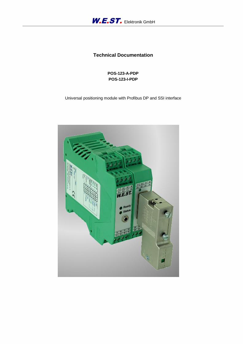
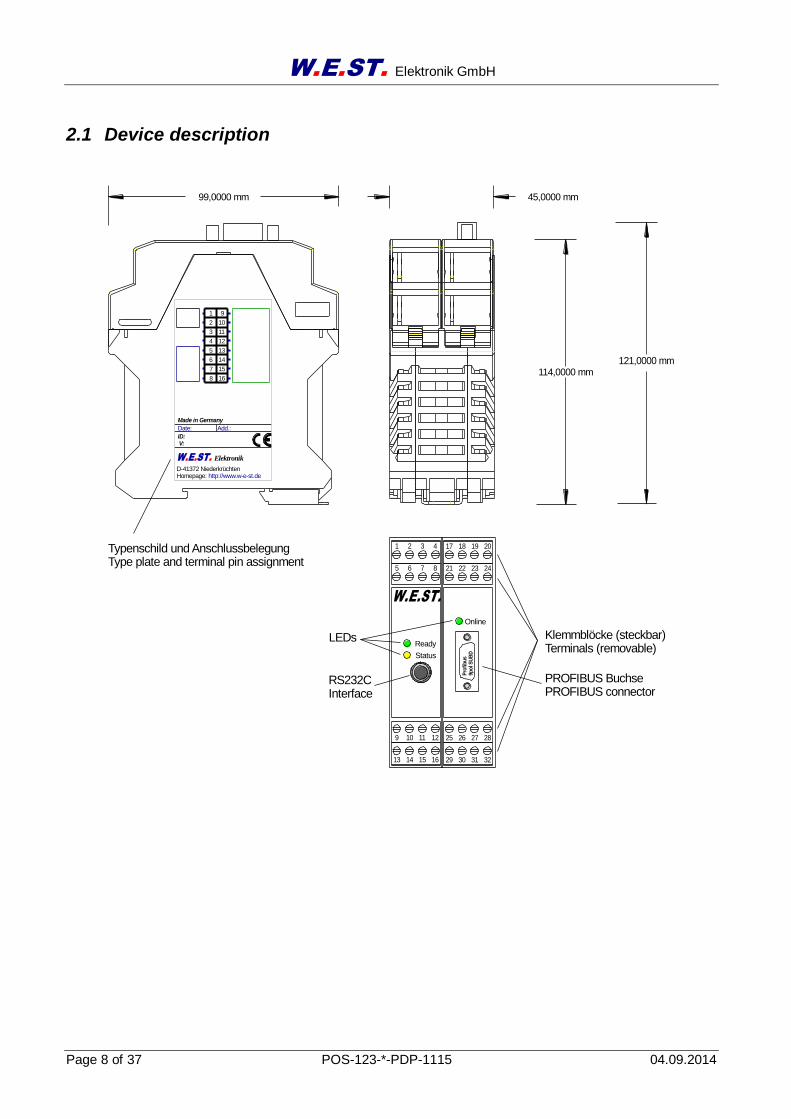
2.1 Device description
V:ID:
Add.:Date:
Made in Germany
W.E.ST.
Ready
Status
1 2 3 4
5 6 7 8
9 10 11 12
14 15 1613
D-41372 NiederkrüchtenHomepage: http://www.w-e-st.de
W.E.ST. Elektronik
8
7
6
5
4
3
2
1
16
15
14
13
12
11
10
9
30 31 3229
26 27 2825
18 19 2017
22 23 2421
Pro
fib
us
9po
l S
UB
D
Online
Klemmblöcke (steckbar)Terminals (removable)
LEDs
RS232C Interface
Typenschild und AnschlussbelegungType plate and terminal pin assignment
45,0000 mm99,0000 mm
114,0000 mm
PROFIBUS BuchsePROFIBUS connector
121,0000 mm
W.E.ST. Elektronik GmbH
Page 9 of 37 POS-123-*-PDP-1115 04.09.2014
3 Use and application
3.1 Installation instructions
This module is designed for installation in a shielded EMC housing (control cabinet). All cables which lead outside must be screened; complete screening is required. It is also necessary to avoid strong electro-magnetic interference sources being installed nearby when using our open and closed loop control modules.
Typical installation location: 24 V control signal area (close to PLC) The devices must be arranged in the control cabinet so that the power section and the signal section are separate from each other. Experience shows that the installation place close to the PLC (24 V area) is most suitable. All digital and analogue inputs and outputs are fitted with filters and surge absorbers in the device.
The module should be installed and wired in accordance with the documentation bearing in mind EMC principles. If other consumers are operated with the same power supply, a star-shaped ground wiring scheme is recommended. The following points must be observed when wiring:
The signal cables must be laid separately from power cables.
Analogue signal cables must be screened.
All other cables must be screened if there are powerful interference sources (frequency converters, power contactors) and cable lengths > 3 m. Inexpensive SMD ferrites can be used with high-frequency radiation.
The screening should be connected to PE (PE terminal) as close to the module as possible. The local requirements for screening must be taken into account in all cases. The screening should be connected to at both ends. Equipotential bonding must be provided where there are differences between the connected electrical components.
If having longer lengths of cable (> 10 m) the diameters and screening measures should be checked by specialists (e. g. for possible interference, noise sources and voltage drop). Special care is required if using cables of over 40 m in length, and if necessary the manufacturer should be consulted if necessary.
A low-resistance connection between PE and the mounting rail should be provided. Transient interference is transmitted from the module directly to the mounting rail and from there to the local earth.
Power should be supplied by a regulated power supply unit (typically a PELV system complying with IEC364-4-4, secure low voltage). The low internal resistance of regulated power supplies gives better interference voltage dissipation, which improves the signal quality of high-resolution sensors in particular. Switched inductances (relays and valve coils) which are connected to the same power supply must always be provided with appropriate overvoltage protection directly at the coil.
W.E.ST. Elektronik GmbH
Page 10 of 37 POS-123-*-PDP-1115 04.09.2014
3.2 Typical system structure
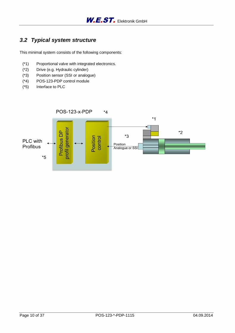
This minimal system consists of the following components:
(*1) Proportional valve with integrated electronics.
(*2) Drive (e.g. Hydraulic cylinder)
(*3) Position sensor (SSI or analogue)
(*4) POS-123-PDP control module
(*5) Interface to PLC
W.E.ST. Elektronik GmbH
Page 11 of 37 POS-123-*-PDP-1115 04.09.2014
time / position
velo
city
P1 P2
V1
V2
acceleration deceleration
P1 P2
V1
V2
acceleration deceleration
High to low speed
Low to high speed
velo
city
time / position
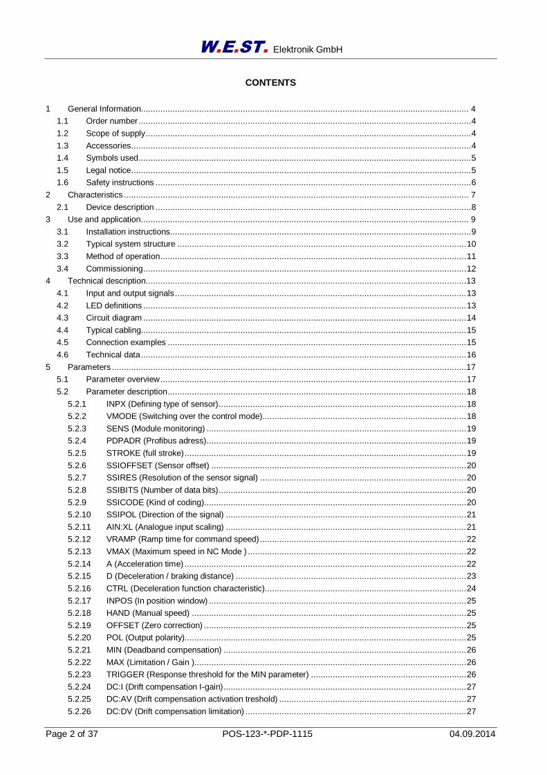
3.3 Method of operation
This module is a further development of the analogue position controller POS-123A.
The POS-123PDP is a module with digital or analogue position measuring and an integrated communication via Profibus DP.
It can be used as an universal axis controller for hydraulic drives.
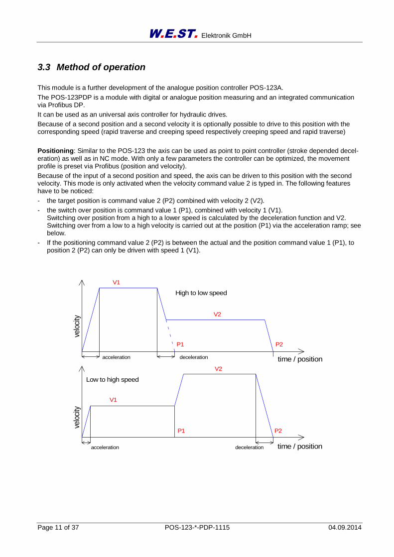
Because of a second position and a second velocity it is optionally possible to drive to this position with the corresponding speed (rapid traverse and creeping speed respectively creeping speed and rapid traverse)
Positioning: Similar to the POS-123 the axis can be used as point to point controller (stroke depended decel-eration) as well as in NC mode. With only a few parameters the controller can be optimized, the movement profile is preset via Profibus (position and velocity).
Because of the input of a second position and speed, the axis can be driven to this position with the second velocity. This mode is only activated when the velocity command value 2 is typed in. The following features have to be noticed:
- the target position is command value 2 (P2) combined with velocity 2 (V2).
- the switch over position is command value 1 (P1), combined with velocity 1 (V1). Switching over position from a high to a lower speed is calculated by the deceleration function and V2. Switching over from a low to a high velocity is carried out at the position (P1) via the acceleration ramp; see below.
- If the positioning command value 2 (P2) is between the actual and the position command value 1 (P1), to position 2 (P2) can only be driven with speed 1 (V1).
W.E.ST. Elektronik GmbH
Page 12 of 37 POS-123-*-PDP-1115 04.09.2014
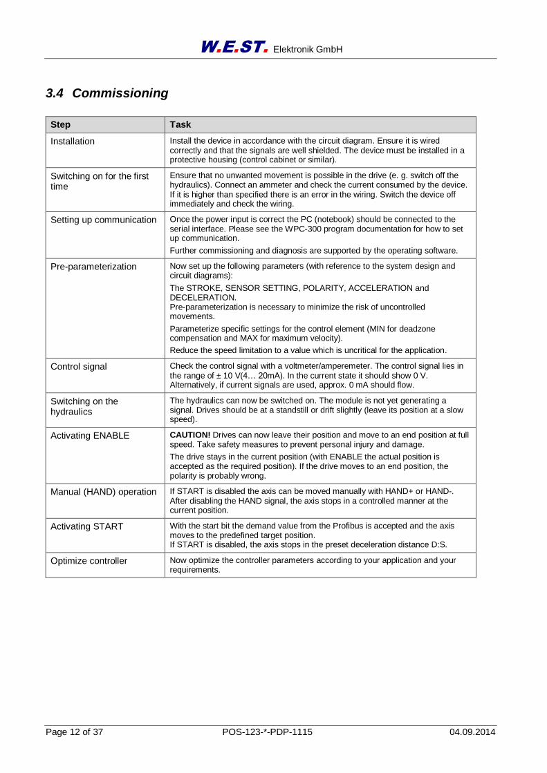
3.4 Commissioning
Step Task
Installation Install the device in accordance with the circuit diagram. Ensure it is wired correctly and that the signals are well shielded. The device must be installed in a protective housing (control cabinet or similar).
Switching on for the first time
Ensure that no unwanted movement is possible in the drive (e. g. switch off the hydraulics). Connect an ammeter and check the current consumed by the device. If it is higher than specified there is an error in the wiring. Switch the device off immediately and check the wiring.
Setting up communication Once the power input is correct the PC (notebook) should be connected to the serial interface. Please see the WPC-300 program documentation for how to set up communication.
Further commissioning and diagnosis are supported by the operating software.
Pre-parameterization Now set up the following parameters (with reference to the system design and circuit diagrams):
The STROKE, SENSOR SETTING, POLARITY, ACCELERATION and DECELERATION. Pre-parameterization is necessary to minimize the risk of uncontrolled movements.
Parameterize specific settings for the control element (MIN for deadzone compensation and MAX for maximum velocity).
Reduce the speed limitation to a value which is uncritical for the application.
Control signal Check the control signal with a voltmeter/amperemeter. The control signal lies in the range of ± 10 V(4… 20mA). In the current state it should show 0 V. Alternatively, if current signals are used, approx. 0 mA should flow.
Switching on the hydraulics
The hydraulics can now be switched on. The module is not yet generating a signal. Drives should be at a standstill or drift slightly (leave its position at a slow speed).
Activating ENABLE CAUTION! Drives can now leave their position and move to an end position at full speed. Take safety measures to prevent personal injury and damage.
The drive stays in the current position (with ENABLE the actual position is accepted as the required position). If the drive moves to an end position, the polarity is probably wrong.
Manual (HAND) operation If START is disabled the axis can be moved manually with HAND+ or HAND-. After disabling the HAND signal, the axis stops in a controlled manner at the current position.
Activating START With the start bit the demand value from the Profibus is accepted and the axis moves to the predefined target position. If START is disabled, the axis stops in the preset deceleration distance D:S.
Optimize controller Now optimize the controller parameters according to your application and your requirements.
W.E.ST. Elektronik GmbH
Page 13 of 37 POS-123-*-PDP-1115 04.09.2014
4 Technical description
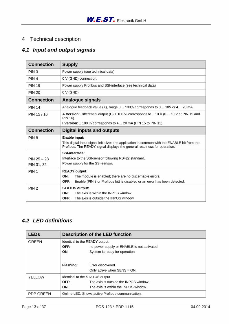
4.1 Input and output signals
4.2 LED definitions
LEDs Description of the LED function
GREEN Identical to the READY output.
OFF: no power supply or ENABLE is not activated
ON: System is ready for operation
Flashing: Error discovered.
Only active when SENS = ON.
YELLOW Identical to the STATUS output.
OFF: The axis is outside the INPOS window.
ON: The axis is within the INPOS window.
PDP GREEN Online-LED. Shows active Profibus-communication.
Connection Supply
PIN 3 Power supply (see technical data)
PIN 4 0 V (GND) connection.
PIN 19 Power supply Profibus and SSI-interface (see technical data)
PIN 20 0 V (GND)
Connection Analogue signals
PIN 14 Analogue feedback value (X), range 0… 100% corresponds to 0… 10V or 4… 20 mA
PIN 15 / 16 A Version: Differential output (U) ± 100 % corresponds to ± 10 V (0… 10 V at PIN 15 and PIN 16).
I Version: ± 100 % corresponds to 4… 20 mA (PIN 15 to PIN 12).
Connection Digital inputs and outputs
PIN 8 Enable input:
This digital input signal initializes the application in common with the ENABLE bit from the Profibus. The READY signal displays the general readiness for operation.
PIN 25 – 28
PIN 31, 32
SSI-interface:
Interface to the SSI-sensor following RS422 standard.
Power supply for the SSI-sensor.
PIN 1 READY output:
ON: The module is enabled; there are no discernable errors.
OFF: Enable (PIN 8 or Profibus bit) is disabled or an error has been detected.
PIN 2 STATUS output:
ON: The axis is within the INPOS window.
OFF: The axis is outside the INPOS window.
W.E.ST. Elektronik GmbH
Page 14 of 37 POS-123-*-PDP-1115 04.09.2014
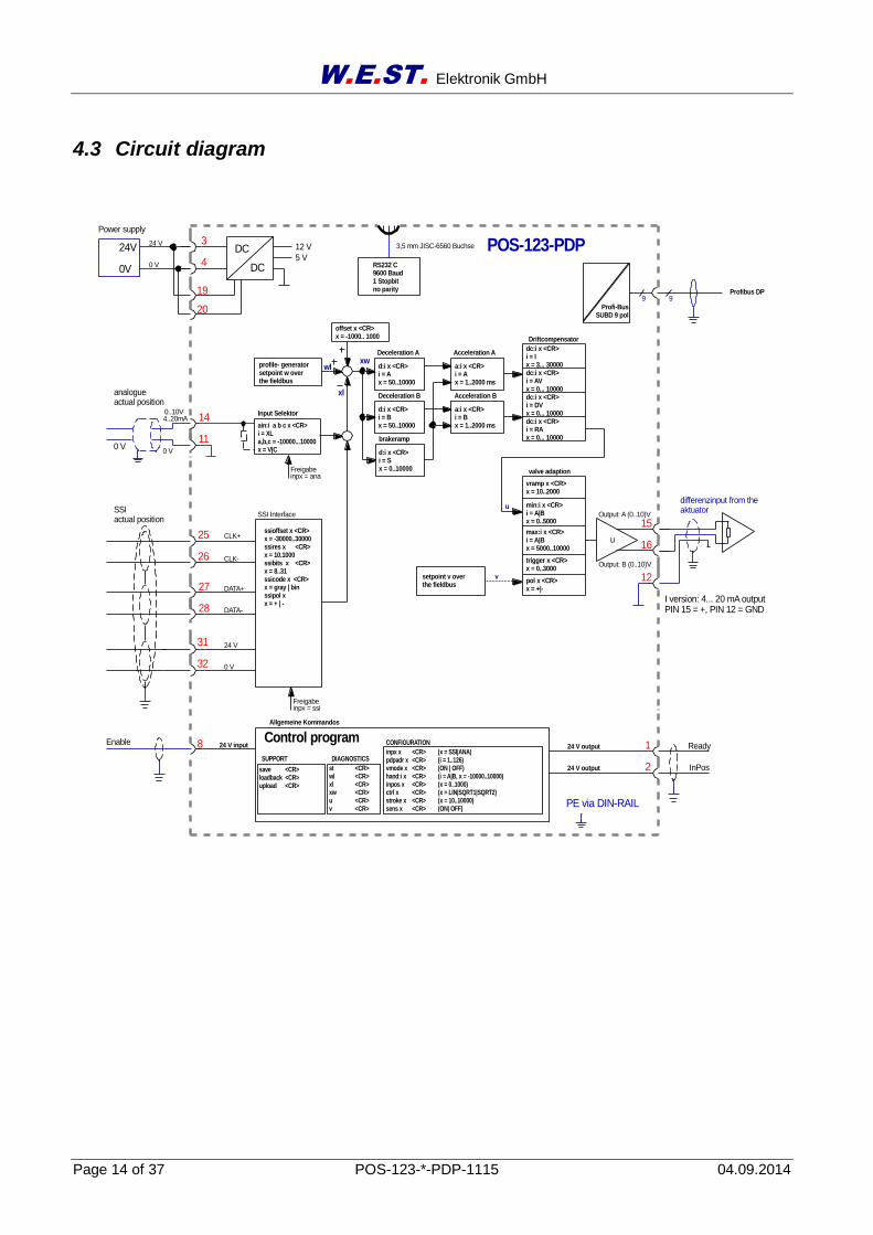
4.3 Circuit diagram
wl
PE via DIN-RAIL
Power supply
3
4
24 V
0 V
1
2
8Enable 24 V output
24 V output
24V
0V
POS-123-PDPDC
DC
12 V
5 V
a:i x <CR>i = Ax = 1..2000 ms
a:i x <CR>i = Bx = 1..2000 ms
SSIactual position
profile- generatorsetpoint w over the fieldbus
Deceleration A
d:i x <CR>i = Ax = 50..10000
d:i x <CR>i = Bx = 50..10000
Acceleration A
Acceleration B
RS232 C9600 Baud1 Stopbitno parity
24 V input
save <CR>loadback <CR>upload <CR>
Allgemeine Kommandos
st <CR>wl <CR>xl <CR>xw <CR>u <CR>v <CR>
inpx x <CR> (x = SSI|ANA)pdpadr x <CR> (i = 1..126)vmode x <CR> (ON | OFF)hand:i x <CR> (i = A|B, x = -10000..10000)inpos x <CR> (x = 0..1000)ctrl x <CR> (x = LIN|SQRT1|SQRT2)stroke x <CR> (x = 10..10000)sens x <CR> (ON| OFF)
Control program
offset x <CR>x = -1000.. 1000
15
16
12
Output: A (0..10)V
Output: B (0..10)V
differenzinput from theaktuator
u
u
27
28
31
32
19
20 Profi-BusSUBD 9 pol
Profibus DP
25
26
SSI Interface
CLK+
CLK-
DATA+
DATA-
24 V
0 V
xw
9 9
ssioffset x <CR> x = -30000..30000ssires x <CR> x = 10.1000ssibits x <CR> x = 8..31ssicode x <CR> x = gray | binssipol xx = + | -
Driftcompensator
dc:i x <CR>i = Ix = 3... 30000
3,5 mm JISC-6560 Buchse
CONFIGURATION
DIAGNOSTICSSUPPORT
14
0 V
0..10V
0 V
11
analogueactual position
4..20mAain:i a b c x <CR>i = XLa,b,c = -10000...10000x = V|C
Input Selektor
inpx = anaFreigabe
inpx = ssiFreigabe
Deceleration Bxl
d:i x <CR>i = Sx = 0..10000
brakeramp
v
Ready
InPos
valve adaption
min:i x <CR>i = A|Bx = 0..5000
max:i x <CR>i = A|Bx = 5000..10000
trigger x <CR>x = 0..3000
pol x <CR>x = +|-
vramp x <CR>x = 10..2000
dc:i x <CR>i = AVx = 0... 10000dc:i x <CR>i = DVx = 0... 10000dc:i x <CR>i = RAx = 0... 10000
setpoint v over the fieldbus
I version: 4... 20 mA outputPIN 15 = +, PIN 12 = GND
W.E.ST. Elektronik GmbH
Page 15 of 37 POS-123-*-PDP-1115 04.09.2014
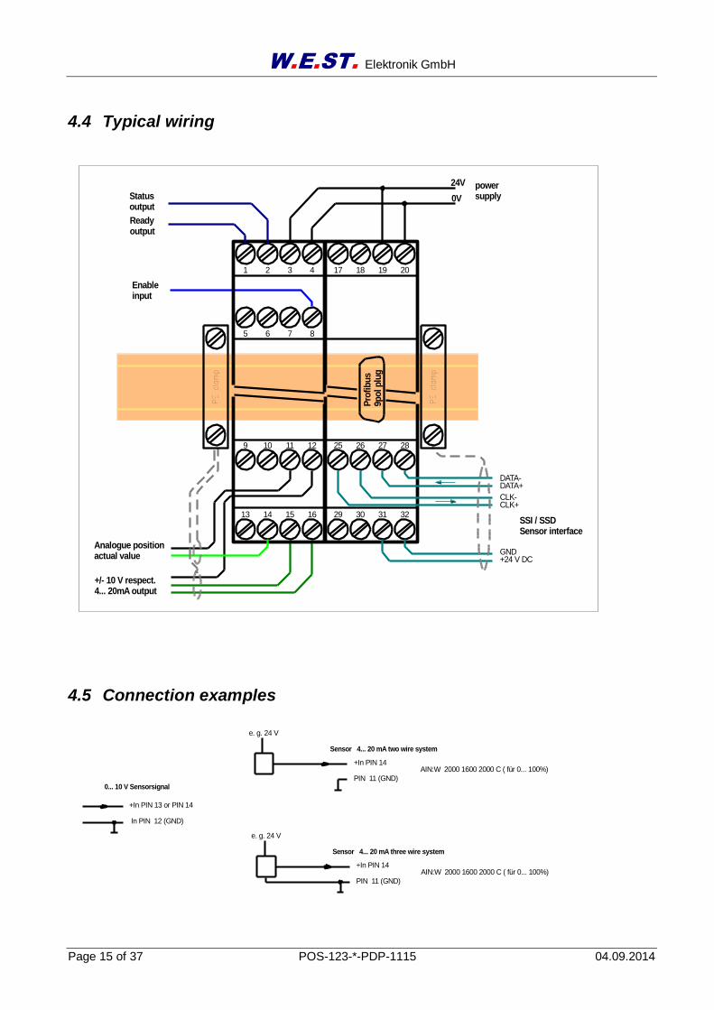
4.4 Typical wiring
4.5 Connection examples
+In PIN 14
PIN 11 (GND)
AIN:W 2000 1600 2000 C ( für 0... 100%)
0... 10 V Sensorsignal
+In PIN 13 or PIN 14
In PIN 12 (GND)
Sensor 4... 20 mA two wire system
e. g. 24 V
+In PIN 14
PIN 11 (GND)
AIN:W 2000 1600 2000 C ( für 0... 100%)
Sensor 4... 20 mA three wire system
e. g. 24 V
powersupply
24V
0V
32313029
28272625
20191817
CLK-CLK+
DATA-DATA+
GND+24 V DC
SSI / SSD Sensor interface
Enableinput
+/- 10 V respect.4... 20mA output
8765
16151413
1211109
4321
Pro
fib
us
9p
ol p
lug
Readyoutput
Statusoutput
Analogue positionactual value
PE clamp
PE clamp
W.E.ST. Elektronik GmbH
Page 16 of 37 POS-123-*-PDP-1115 04.09.2014
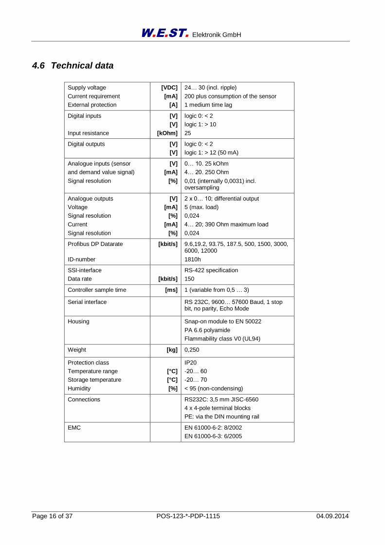
4.6 Technical data
Supply voltage
Current requirement
External protection
[VDC]
[mA]
[A]
24… 30 (incl. ripple)
200 plus consumption of the sensor
1 medium time lag
Digital inputs
Input resistance
[V]
[V]
[kOhm]
logic 0: < 2
logic 1: > 10
25
Digital outputs [V]
[V]
logic 0: < 2
logic 1: > 12 (50 mA)
Analogue inputs (sensor
and demand value signal)
Signal resolution
[V]
[mA]
[%]
0… 10. 25 kOhm
4… 20. 250 Ohm
0,01 (internally 0,0031) incl. oversampling
Analogue outputs
Voltage
Signal resolution
Current
Signal resolution
[V]
[mA]
[%]
[mA]
[%]
2 x 0… 10; differential output
5 (max. load)
0,024
4… 20; 390 Ohm maximum load
0,024
Profibus DP Datarate
ID-number
[kbit/s] 9.6,19.2, 93.75, 187.5, 500, 1500, 3000, 6000, 12000
1810h
SSI-interface
Data rate
[kbit/s]
RS-422 specification
150
Controller sample time [ms] 1 (variable from 0,5 … 3)
Serial interface
RS 232C, 9600… 57600 Baud, 1 stop bit, no parity, Echo Mode
Housing Snap-on module to EN 50022
PA 6.6 polyamide
Flammability class V0 (UL94)
Weight [kg] 0,250
Protection class
Temperature range
Storage temperature
Humidity
[°C]
[°C]
[%]
IP20
-20… 60
-20… 70
< 95 (non-condensing)
Connections RS232C: 3,5 mm JISC-6560
4 x 4-pole terminal blocks
PE: via the DIN mounting rail
EMC
EN 61000-6-2: 8/2002
EN 61000-6-3: 6/2005
W.E.ST. Elektronik GmbH
Page 17 of 37 POS-123-*-PDP-1115 04.09.2014
5 Parameters
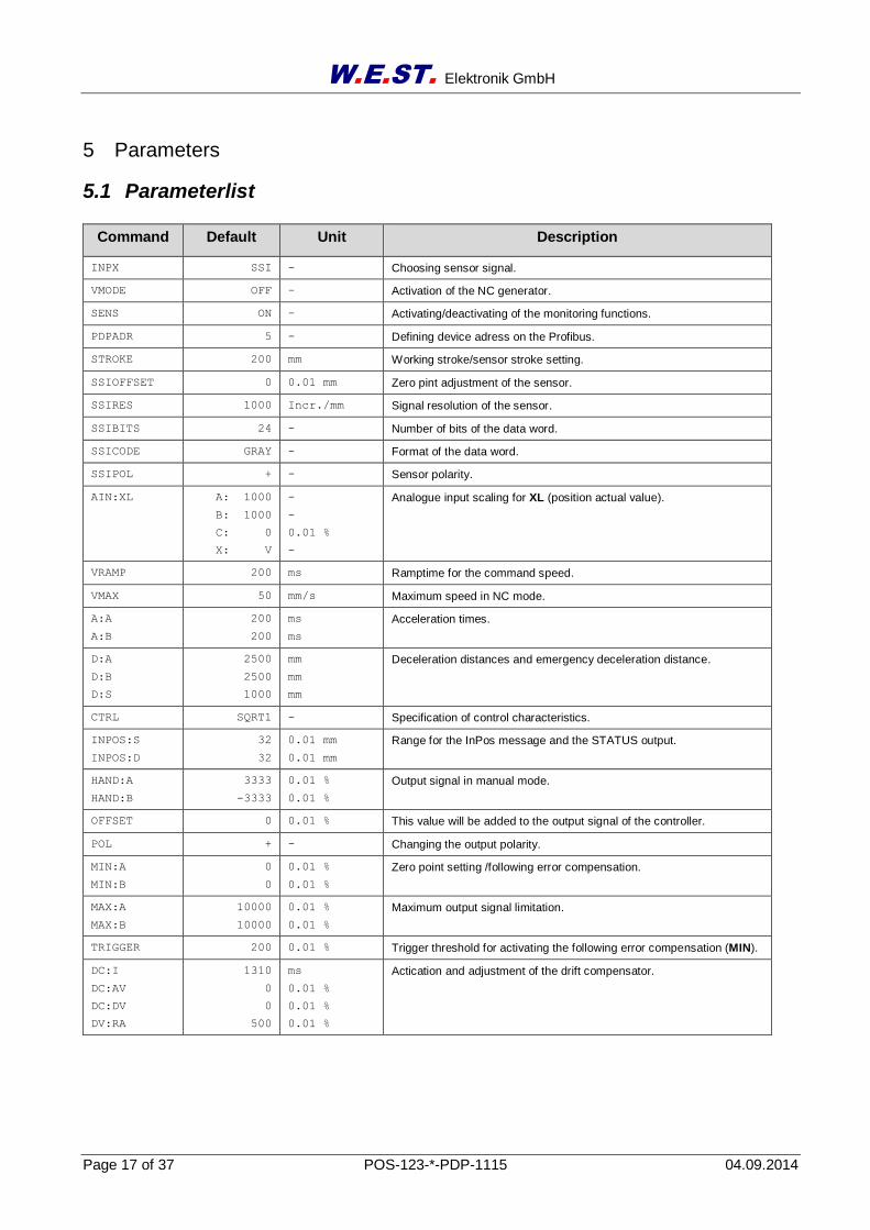
5.1 Parameterlist
Command Default Unit Description
INPX SSI - Choosing sensor signal.
VMODE OFF - Activation of the NC generator.
SENS ON - Activating/deactivating of the monitoring functions.
PDPADR 5 - Defining device adress on the Profibus.
STROKE 200 mm Working stroke/sensor stroke setting.
SSIOFFSET 0 0.01 mm Zero pint adjustment of the sensor.
SSIRES 1000 Incr./mm Signal resolution of the sensor.
SSIBITS 24 - Number of bits of the data word.
SSICODE GRAY - Format of the data word.
SSIPOL + - Sensor polarity.
AIN:XL A: 1000
B: 1000
C: 0
X: V
-
-
0.01 %
-
Analogue input scaling for XL (position actual value).
VRAMP 200 ms Ramptime for the command speed.
VMAX 50 mm/s Maximum speed in NC mode.
A:A
A:B
200
200
ms
ms
Acceleration times.
D:A
D:B
D:S
2500
2500
1000
mm
mm
mm
Deceleration distances and emergency deceleration distance.
CTRL SQRT1 - Specification of control characteristics.
INPOS:S
INPOS:D
32
32
0.01 mm
0.01 mm
Range for the InPos message and the STATUS output.
HAND:A
HAND:B
3333
-3333
0.01 %
0.01 %
Output signal in manual mode.
OFFSET 0 0.01 % This value will be added to the output signal of the controller.
POL + - Changing the output polarity.
MIN:A
MIN:B
0
0
0.01 %
0.01 %
Zero point setting /following error compensation.
MAX:A
MAX:B
10000
10000
0.01 %
0.01 %
Maximum output signal limitation.
TRIGGER 200 0.01 % Trigger threshold for activating the following error compensation (MIN).
DC:I
DC:AV
DC:DV
DV:RA
1310
0
0
500
ms
0.01 %
0.01 %
0.01 %
Actication and adjustment of the drift compensator.
W.E.ST. Elektronik GmbH
Page 18 of 37 POS-123-*-PDP-1115 04.09.2014
5.2 Parameter description
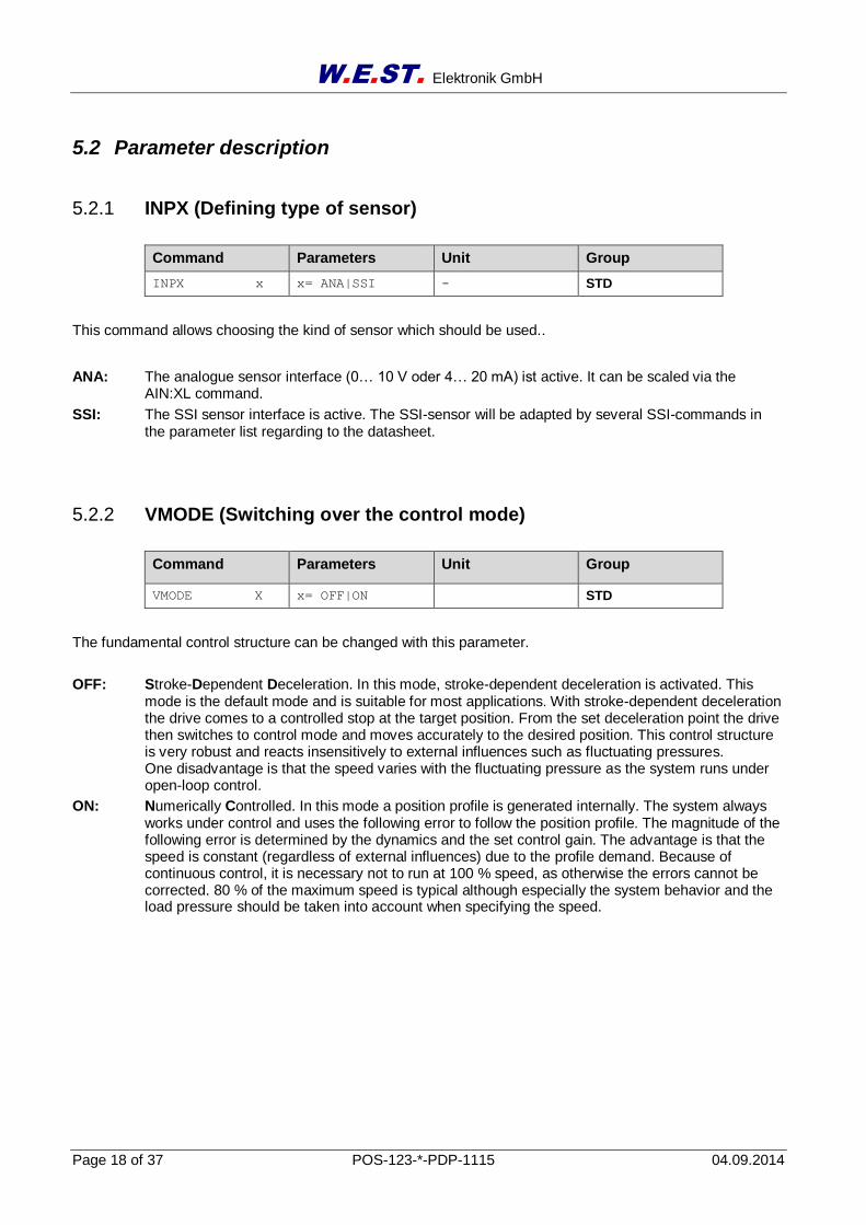
5.2.1 INPX (Defining type of sensor)
Command Parameters Unit Group
INPX x x= ANA|SSI - STD
This command allows choosing the kind of sensor which should be used..
ANA: The analogue sensor interface (0… 10 V oder 4… 20 mA) ist active. It can be scaled via the AIN:XL command.
SSI: The SSI sensor interface is active. The SSI-sensor will be adapted by several SSI-commands in the parameter list regarding to the datasheet.
5.2.2 VMODE (Switching over the control mode)
Command Parameters Unit Group
VMODE X x= OFF|ON STD
The fundamental control structure can be changed with this parameter.
OFF: Stroke-Dependent Deceleration. In this mode, stroke-dependent deceleration is activated. This mode is the default mode and is suitable for most applications. With stroke-dependent deceleration the drive comes to a controlled stop at the target position. From the set deceleration point the drive then switches to control mode and moves accurately to the desired position. This control structure is very robust and reacts insensitively to external influences such as fluctuating pressures. One disadvantage is that the speed varies with the fluctuating pressure as the system runs under open-loop control.
ON: Numerically Controlled. In this mode a position profile is generated internally. The system always works under control and uses the following error to follow the position profile. The magnitude of the following error is determined by the dynamics and the set control gain. The advantage is that the speed is constant (regardless of external influences) due to the profile demand. Because of continuous control, it is necessary not to run at 100 % speed, as otherwise the errors cannot be corrected. 80 % of the maximum speed is typical although especially the system behavior and the load pressure should be taken into account when specifying the speed.
W.E.ST. Elektronik GmbH
Page 19 of 37 POS-123-*-PDP-1115 04.09.2014
5.2.3 SENS (Module monitoring)
Command Parameters Unit Group
SENS x x= ON|OFF - STD
This command is used to activate/deactivate the monitoring functions (4… 20 mA sensors, SSI-sensors and internal failures) of the module.
ON: All monitoring functions are active. Detected failures can be reset by deactivating the ENABLE in-put.
OFF: No monitoring function is active.
Normally the monitoring functions are always active because otherwise no errors are detectable via the READY output. Deactivating is possible mainly for troubleshooting.
5.2.4 PDPADR (Profibus address)
Command Parameters Unit Group
PDPADR x x= 1… 126 - STD
This command defines the address of the module on the Profibus. If the address should be changed via Profibus, 126 has to be chosen.
Attention: If the address will be changed via Profibus, there is no change in the parameter list. It is still shown 126 but the address chosen via Profibus is active and the only one can be used.
5.2.5 STROKE (full stroke)
Command Parameters Unit Group
STROKE X x= 2… 3000 mm STD
This command defines the full stroke, respectively the length of the sensor. If the demand is set incorrectly, this leads to incorrect system settings, and the dependent parameters such as speed and gain cannot be calculated correctly.
W.E.ST. Elektronik GmbH
Page 20 of 37 POS-123-*-PDP-1115 04.09.2014
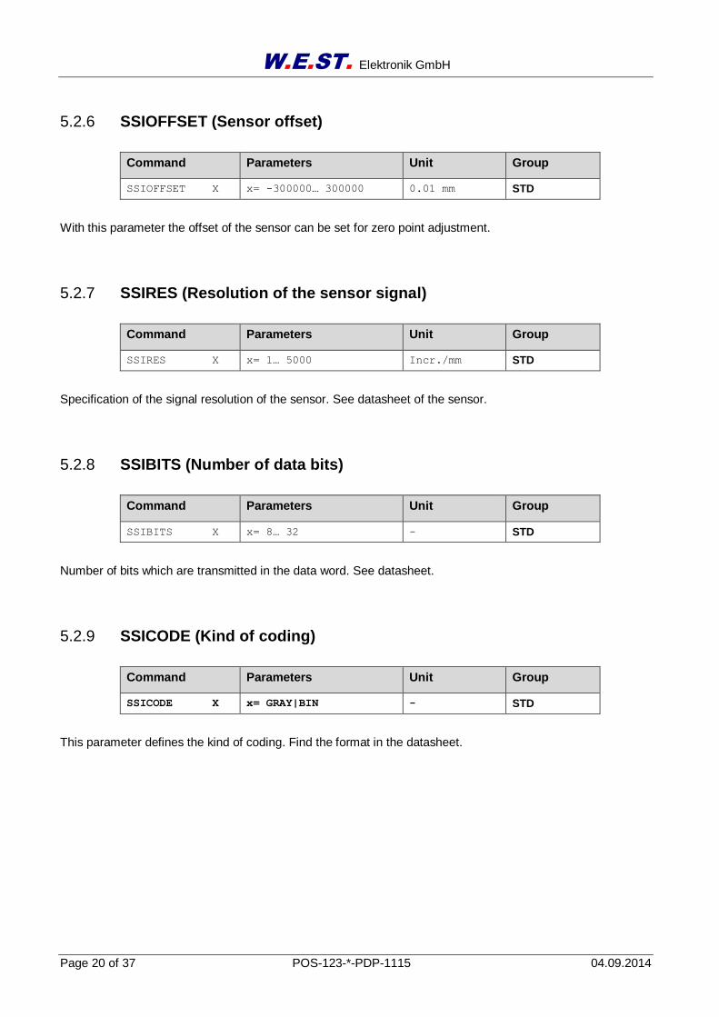
5.2.6 SSIOFFSET (Sensor offset)
Command Parameters Unit Group
SSIOFFSET X x= -300000… 300000 0.01 mm STD
With this parameter the offset of the sensor can be set for zero point adjustment.
5.2.7 SSIRES (Resolution of the sensor signal)
Command Parameters Unit Group
SSIRES X x= 1… 5000 Incr./mm STD
Specification of the signal resolution of the sensor. See datasheet of the sensor.
5.2.8 SSIBITS (Number of data bits)
Command Parameters Unit Group
SSIBITS X x= 8… 32 - STD
Number of bits which are transmitted in the data word. See datasheet.
5.2.9 SSICODE (Kind of coding)
Command Parameters Unit Group
SSICODE X x= GRAY|BIN - STD
This parameter defines the kind of coding. Find the format in the datasheet.
W.E.ST. Elektronik GmbH
Page 21 of 37 POS-123-*-PDP-1115 04.09.2014
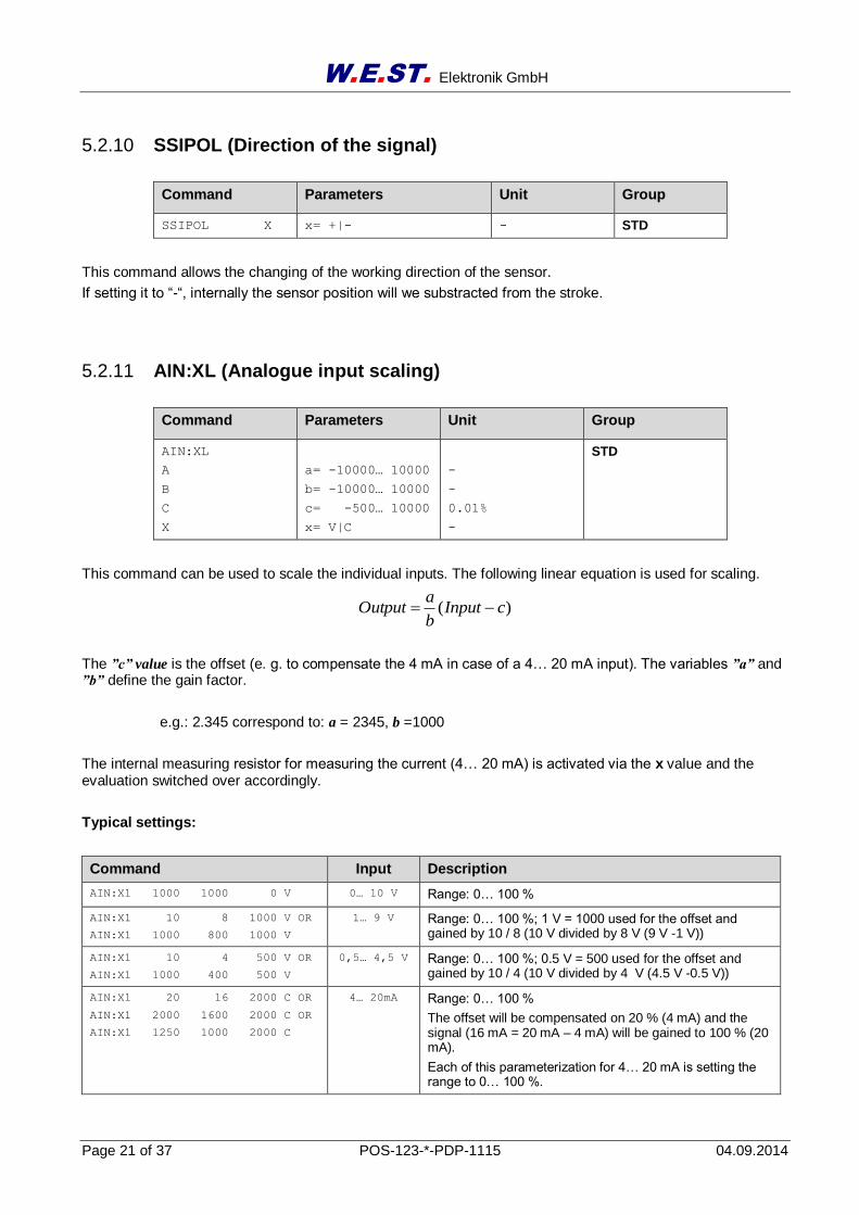
5.2.10 SSIPOL (Direction of the signal)
Command Parameters Unit Group
SSIPOL X x= +|- - STD
This command allows the changing of the working direction of the sensor.
If setting it to “-“, internally the sensor position will we substracted from the stroke.
5.2.11 AIN:XL (Analogue input scaling)
Command Parameters Unit Group
AIN:XL
A
B
C
X
a= -10000… 10000
b= -10000… 10000
c= -500… 10000
x= V|C
-
-
0.01%
-
STD
This command can be used to scale the individual inputs. The following linear equation is used for scaling.
)( cInputb
aOutput
The ”c” value is the offset (e. g. to compensate the 4 mA in case of a 4… 20 mA input). The variables ”a” and ”b” define the gain factor.
e.g.: 2.345 correspond to: a = 2345, b =1000
The internal measuring resistor for measuring the current (4… 20 mA) is activated via the x value and the evaluation switched over accordingly.
Typical settings:
Command Input Description
AIN:X1 1000 1000 0 V 0… 10 V Range: 0… 100 %
AIN:X1 10 8 1000 V OR
AIN:X1 1000 800 1000 V
1… 9 V Range: 0… 100 %; 1 V = 1000 used for the offset and gained by 10 / 8 (10 V divided by 8 V (9 V -1 V))
AIN:X1 10 4 500 V OR
AIN:X1 1000 400 500 V
0,5… 4,5 V Range: 0… 100 %; 0.5 V = 500 used for the offset and gained by 10 / 4 (10 V divided by 4 V (4.5 V -0.5 V))
AIN:X1 20 16 2000 C OR
AIN:X1 2000 1600 2000 C OR
AIN:X1 1250 1000 2000 C
4… 20mA Range: 0… 100 %
The offset will be compensated on 20 % (4 mA) and the signal (16 mA = 20 mA – 4 mA) will be gained to 100 % (20 mA).
Each of this parameterization for 4… 20 mA is setting the range to 0… 100 %.
W.E.ST. Elektronik GmbH
Page 22 of 37 POS-123-*-PDP-1115 04.09.2014
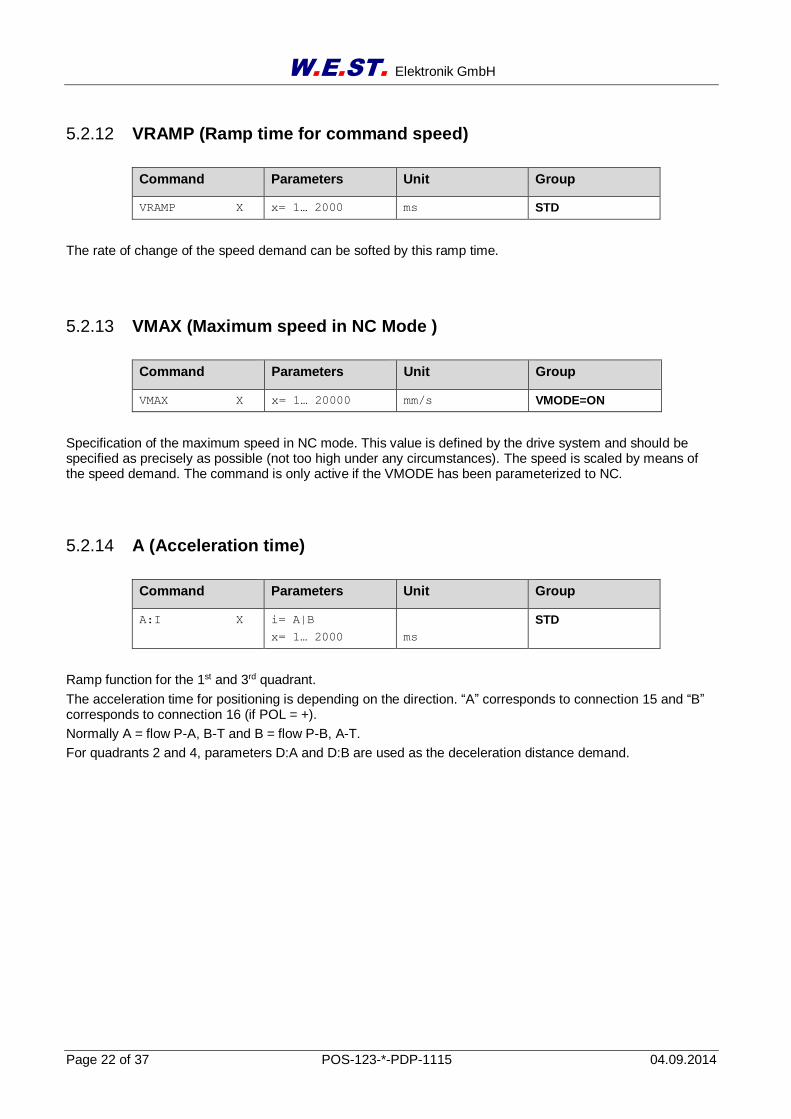
5.2.12 VRAMP (Ramp time for command speed)
Command Parameters Unit Group
VRAMP X x= 1… 2000 ms STD
The rate of change of the speed demand can be softed by this ramp time.
5.2.13 VMAX (Maximum speed in NC Mode )
Command Parameters Unit Group
VMAX X x= 1… 20000 mm/s VMODE=ON
Specification of the maximum speed in NC mode. This value is defined by the drive system and should be specified as precisely as possible (not too high under any circumstances). The speed is scaled by means of the speed demand. The command is only active if the VMODE has been parameterized to NC.
5.2.14 A (Acceleration time)
Command Parameters Unit Group
A:I X i= A|B
x= 1… 2000
ms
STD
Ramp function for the 1st and 3rd quadrant.
The acceleration time for positioning is depending on the direction. “A” corresponds to connection 15 and “B” corresponds to connection 16 (if POL = +).
Normally A = flow P-A, B-T and B = flow P-B, A-T.
For quadrants 2 and 4, parameters D:A and D:B are used as the deceleration distance demand.
W.E.ST. Elektronik GmbH
Page 23 of 37 POS-123-*-PDP-1115 04.09.2014
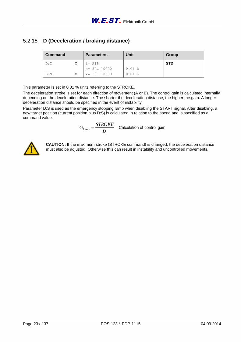
5.2.15 D (Deceleration / braking distance)
Command Parameters Unit Group
D:I X
D:S X
i= A|B
x= 50… 10000
x= 0… 10000
0.01 %
0.01 %
STD
This parameter is set in 0.01 % units referring to the STROKE.
The deceleration stroke is set for each direction of movement (A or B). The control gain is calculated internally depending on the deceleration distance. The shorter the deceleration distance, the higher the gain. A longer deceleration distance should be specified in the event of instability.
Parameter D:S is used as the emergency stopping ramp when disabling the START signal. After disabling, a new target position (current position plus D:S) is calculated in relation to the speed and is specified as a command value.
Calculation of control gain
CAUTION: If the maximum stroke (STROKE command) is changed, the deceleration distance must also be adjusted. Otherwise this can result in instability and uncontrolled movements.
i
InternD
STROKEG
W.E.ST. Elektronik GmbH
Page 24 of 37 POS-123-*-PDP-1115 04.09.2014
5.2.16 CTRL (Deceleration function characteristic)
Command Parameters Unit Group
CTRL X x= LIN|SQRT1|SQRT2 - STD
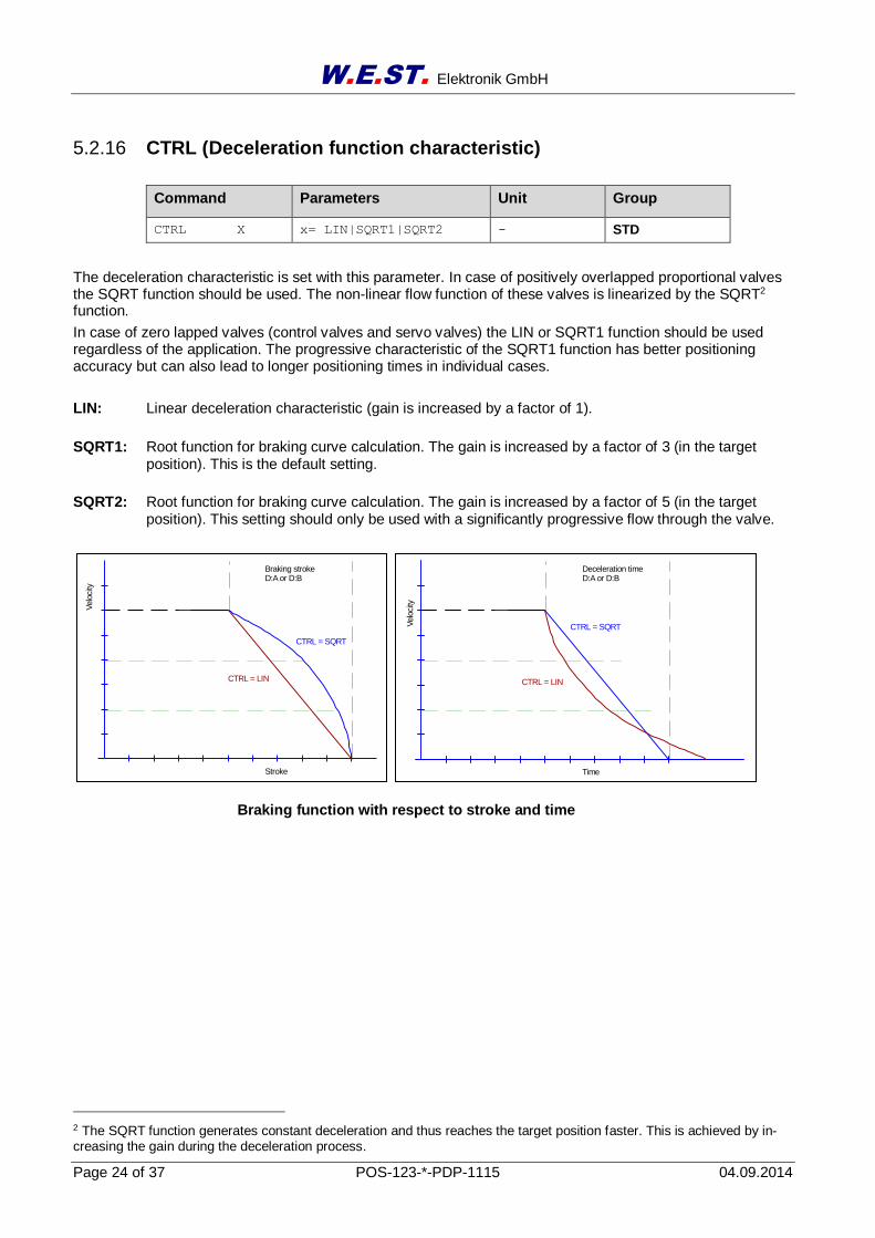
The deceleration characteristic is set with this parameter. In case of positively overlapped proportional valves the SQRT function should be used. The non-linear flow function of these valves is linearized by the SQRT2 function.
In case of zero lapped valves (control valves and servo valves) the LIN or SQRT1 function should be used regardless of the application. The progressive characteristic of the SQRT1 function has better positioning accuracy but can also lead to longer positioning times in individual cases.
LIN: Linear deceleration characteristic (gain is increased by a factor of 1).
SQRT1: Root function for braking curve calculation. The gain is increased by a factor of 3 (in the target position). This is the default setting.
SQRT2: Root function for braking curve calculation. The gain is increased by a factor of 5 (in the target position). This setting should only be used with a significantly progressive flow through the valve.
2 The SQRT function generates constant deceleration and thus reaches the target position faster. This is achieved by in-creasing the gain during the deceleration process.
Braking function with respect to stroke and time
Stroke
Velo
city
Braking strokeD:A or D:B
CTRL = LIN
CTRL = SQRT
Time
Velo
city
Deceleration timeD:A or D:B
CTRL = LIN
CTRL = SQRT
W.E.ST. Elektronik GmbH
Page 25 of 37 POS-123-*-PDP-1115 04.09.2014
5.2.17 INPOS (In position window)
Command Parameters Unit Group
INPOS:I X i= D|S
x= 0… 5000
0.01 mm
STD
This parameter is entered in 0.01mm. The INPOS command defines a monitoring window in which the INPOS message is displayed. The monitoring window is placed centrally on the required position value. The actual position value within this window is signalled by the INPOS message at the status output (INPOS:S). The positioning process is not influenced by this message. The control function remains active. In NC Mode this message is used to monitor the following error (INPOS:D). Depending on the command VMODE the INPOS:D or INPOS:S window ist used and send to the Profibus and to the STATUS output and LED.
5.2.18 HAND (Manual speed)
Command Parameters Unit Group
HAND:I X i= A|B
x= -10000… 10000
0.01 %
STD
The manual speeds are set with these parameters. The drive moves in a controlled manner in the defined direction when the manual signal is active. After the manual signal has been disabled, the drive remains under control in the current position.
In case of a fault (position sensor fault) the drive can still be moved with the manual function. The output will be switched of when hand signals are turned off.
The manual speed is also limited by the (external) speed demand (MIN evaluation).
5.2.19 OFFSET (Zero correction)
Command Parameters Unit Group
OFFSET X x= -2000… 2000 0.01 % STD
This parameter is entered in 0.01 % units.
The offset value is added to the output value. Valve zero offsets can be compensated with this parameter.
5.2.20 POL (Output polarity)
Command Parameters Unit Group
POL X x= +|- - STD
This command enables the output signal polarity to be reversed.
W.E.ST. Elektronik GmbH
Page 26 of 37 POS-123-*-PDP-1115 04.09.2014
5.2.21 MIN (Deadband compensation)
5.2.22 MAX (Limitation / Gain )
5.2.23 TRIGGER (Response threshold for the MIN parameter)
Command Parameters Unit Group
MIN:I X
MAX:I X
TRIGGER X
i= A|B
x= 0… 5000
x= 5000… 10000
x= 0… 2000
-
0.01 %
0.01 %
0.01 %
STD
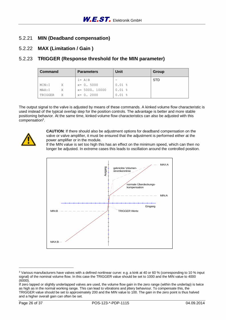
The output signal to the valve is adjusted by means of these commands. A kinked volume flow characteristic is used instead of the typical overlap step for the position controls. The advantage is better and more stable positioning behavior. At the same time, kinked volume flow characteristics can also be adjusted with this compensation3.
CAUTION: If there should also be adjustment options for deadband compensation on the valve or valve amplifier, it must be ensured that the adjustment is performed either at the power amplifier or in the module. If the MIN value is set too high this has an effect on the minimum speed, which can then no longer be adjusted. In extreme cases this leads to oscillation around the controlled position.
3 Various manufacturers have valves with a defined nonlinear curve: e.g. a kink at 40 or 60 % (corresponding to 10 % input signal) of the nominal volume flow. In this case the TRIGGER value should be set to 1000 and the MIN value to 4000 (6000). If zero lapped or slightly underlapped valves are used, the volume flow gain in the zero range (within the underlap) is twice as high as in the normal working range. This can lead to vibrations and jittery behaviour. To compensate this, the TRIGGER value should be set to approximately 200 and the MIN value to 100. The gain in the zero point is thus halved and a higher overall gain can often be set.
MAX:A
MIN:A
MIN:B
MAX:B
Eingang
Aus
gang geknickte Volumen-
stromkennlinie
normale Überdeckungs-kompensation
TRIGGER Werte
W.E.ST. Elektronik GmbH
Page 27 of 37 POS-123-*-PDP-1115 04.09.2014
5.2.24 DC:I (Drift compensation I-gain)
5.2.25 DC:AV (Drift compensation activation treshold)
5.2.26 DC:DV (Drift compensation limitation)
5.2.27 DC:RA (Drift compensation target range)
Command Parameters Unit Group
DC:I X
DC:AV X
DC:DV X
DC:RA X
x= 3… 30050
x= 0… 10000
x= 0… 10000
x= 0… 10000
ms
0.01 %
0.01 %
0.01 %
STD
The drift compensation is a possible way to prevent drift axis in the target position.
By adding a switch integral part of the alternate value is the axis effectively held in position. The parameter “DC: I” define the setting time of the integral share.
The activation threshold "DC: AV" is in percent of the stated value.
Below the absolute value of the signal in relation to this parameter is the drift Compensator activated.
Immediately to the position of the target position can be disabled the integrator again, this is the commando "DC: DV", whose value is also in percent of the value entered.
The target range of the drift compensation is determined by the command “DC: RA”.
In default of the module the drift compensation is switched off by setting the parameters "DC: AV" and “DC: DV” to “0”.
5.2.28 PROCESS DATA (Monitoring)
Command Parameters Unit
WL
XL
V
XW
U
Demand value
Actual value
Speed demand
Error signal
Control signal
mm
mm
%
mm
%
The process data are the variables which can be observed continuously on the monitor or on the oscilloscope.
W.E.ST. Elektronik GmbH
Page 28 of 37 POS-123-*-PDP-1115 04.09.2014
6 Profibus DP interface
6.1 Profibus functions
The module supports all baud rates from 9,6 kbit/s up to 12000 kbit/s with auto detection of the baud rate. The functionality is defined in IEC 61158. The Profibus address can be programmed by a terminal program, WPC-300 or online via the Profibus. A diagnostic LED indicates the online status.
6.2 Installation
A typical screened Profibus plug (D-Sub 9pol with switchable termination) is mandatory. Every Profibus seg-ment must be provided with an active bus termination at the beginning and at the end. The termination is al-ready integrated in all common Profibus plugs and can be activated by DIL switches. The Profibus cable must be screened. PIN 17 has to be connected with PE (low impedance).
6.3 GSD Configuration File
The GSD data file is available on our homepage: http://www.w-e-st.de/files/software/hms_1810.gsd
The communication parameters are 16 bytes (8 words) for IN/OUT variables.
W.E.ST. Elektronik GmbH
Page 29 of 37 POS-123-*-PDP-1115 04.09.2014
6.4 Description Profibus DP interface
The resolution (data via Profibus) of the command position is defined by the actual sensor resolution. The module works always with full sensor accuracy. The scaled speed is defined by 0x3fff (16373) for 100% of the maximum programmed speed.
Optional two positions and two speeds can be sent to the module. In this mode high/low speed or low/high speed profiles are generated automatically. This mode is deactivated by programming zero for speed 2.
The module will be controlled by the control word, the command positions and speeds:
ENABLE: is additionally required to the hardware ENABLE.
START: the new command position is taken over by a signal change from low to high. By deactivation of this bit, the system stops via a programmed deceleration ramp.
HAND+, HAND-: Manual mode
Command values:
Command position 1 and 2: related to the sensor resolution.
Command velocity 1 and 2: 100 % corresponds to 0x3fff. Attention: The maximum value must not be exceeded (uncontrollable behaviour)!
Feedback of the status word, the command position and the actual position
READY: System is ready for positioning.
InPos: In position signal, depending on parameterization.
Sensor error: if the monitoring is activated and a sensor failure occures, the READY signal will be deactivated.
Attention: In case of a sensor failure the hardware-enable-signal has to be deactivated.
Actual values:
Command position: Can be interpreted variously according to the mode. Normal = preset command position, NC-Modus = calculated command position of the generator,
Actual position: corresponding to the sensor solution.
Control deviation (x-w): according to the sensor resolution. In the NC-mode shows the contouring error (difference in the value of the nominal value gen-erator to the actual value). Control deviation (x-w): according to the sensor resolution.
W.E.ST. Elektronik GmbH
Page 30 of 37 POS-123-*-PDP-1115 04.09.2014
6.5 Commands via Profibus
16 data bytes are sent to the module.
Nr. Byte Function Comment
1 0 Control word Hi-Byte
2 1 Control word Lo-Byte not used
3 2 Command position 1 Hi-Byte defined by the resolution of the sensor
4 3 Command position 1
5 4 Command position 1
6 5 Command position 1 Lo-Byte
7 6 Velocity 1 Hi-Byte from 0… 3fff hex
8 7 Velocity 1 Lo-Byte
9 8 Command position 2 Hi-Byte active, if a second velocity is programmed ( Byte 13 and 14 ). Defined by the resolu-tion of the sensor.
10 9 Command position 2
11 10 Command position 2
12 11 Command position 2 Lo-Byte
13 12 Velocity 2 Hi-Byte from 0… 3fff hex
14 13 Velocity 2 Lo-Byte
15 14 - not used
16 15 -
The control word is coded as the following:
Byte 0 – Control word Hi-Byte
Nr. Bit Function
1 0
2 1
3 2
4 3
5 4 Hand+ 1= active
6 5 Hand- 1= active
7 6 Start 1= active
8 7 Enable (combined with hardware enable) 1= active
The enable bit is combined with the external enable input, that means both signals must exist, in order to ena-ble the axes.
W.E.ST. Elektronik GmbH
Page 31 of 37 POS-123-*-PDP-1115 04.09.2014
6.6 Data send to Profibus
Totally 16 Bytes will be sent to the Profibus.
Nr. Byte Function Comment
1 0 Status word Hi-Byte
2 1 Status word Lo-Byte not used
3 2 Actual position Hi-Byte displayed in resolution of the positioning sensor
4 3 Actual position
5 4 Actual position
6 5 Actual position Lo-Byte
7 6 Internal command position Hi-Byte displayed in resolution of the positioning sensor
8 7 Internal command position
9 8 Internal command position
10 9 Internal command position Lo-Byte
11 10 Control deviation (x-w) Hi-Byte displayed in resolution of the positioning sensor
12 11 Control deviation (x-w)
13 12 Control deviation (x-w)
14 13 Control deviation (x-w) Lo-Byte
15 14 - not used
16 15 - not used
The status word is coded as the following:
Byte 0 – Status word Hi-Byte
Nr. Bit Function
1 0
2 1
3 2
4 3
5 4
6 5
7 6 INPOS 1= actual value in range
8 7 READY 1= readiness for operation
W.E.ST. Elektronik GmbH
Page 32 of 37 POS-123-*-PDP-1115 04.09.2014
6.7 ST (Status request)
Command Parameters Unit Group
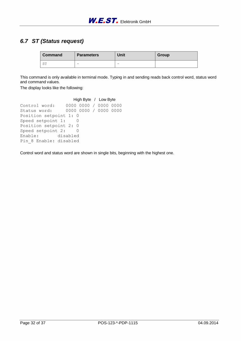
ST - -
This command is only available in terminal mode. Typing in and sending reads back control word, status word and command values.
The display looks like the following:
High Byte / Low Byte
Control word: 0000 0000 / 0000 0000
Status word: 0000 0000 / 0000 0000
Position setpoint 1: 0
Speed setpoint 1: 0
Position setpoint 2: 0
Speed setpoint 2: 0
Enable: disabled
Pin_8 Enable: disabled
Control word and status word are shown in single bits, beginning with the highest one.
W.E.ST. Elektronik GmbH
Page 33 of 37 POS-123-*-PDP-1115 04.09.2014
7 Appendix
7.1 Failure monitoring
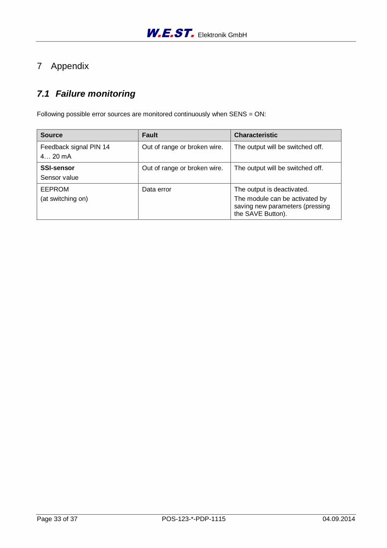
Following possible error sources are monitored continuously when SENS = ON:
Source Fault Characteristic
Feedback signal PIN 14
4… 20 mA
Out of range or broken wire. The output will be switched off.
SSI-sensor
Sensor value
Out of range or broken wire. The output will be switched off.
EEPROM
(at switching on)
Data error The output is deactivated.
The module can be activated by saving new parameters (pressing the SAVE Button).
W.E.ST. Elektronik GmbH
Page 34 of 37 POS-123-*-PDP-1115 04.09.2014
7.2 Troubleshooting
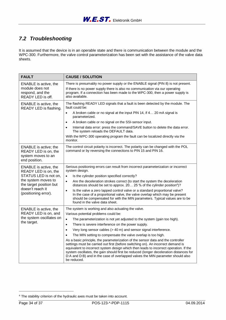
It is assumed that the device is in an operable state and there is communication between the module and the WPC-300. Furthermore, the valve control parameterization has been set with the assistance of the valve data sheets.
FAULT CAUSE / SOLUTION
ENABLE is active, the module does not respond, and the READY LED is off.
There is presumably no power supply or the ENABLE signal (PIN 8) is not present.
If there is no power supply there is also no communication via our operating program. If a connection has been made to the WPC-300, then a power supply is also available.
ENABLE is active, the READY LED is flashing.
The flashing READY LED signals that a fault is been detected by the module. The fault could be:
A broken cable or no signal at the input PIN 14, if 4… 20 mA signal is parameterized.
A broken cable or no signal on the SSI-sensor input.
Internal data error: press the command/SAVE button to delete the data error. The system reloads the DEFAULT data.
With the WPC-300 operating program the fault can be localized directly via the monitor.
ENABLE is active; the READY LED is on, the system moves to an end position.
The control circuit polarity is incorrect. The polarity can be changed with the POL command or by reversing the connections to PIN 15 and PIN 16.
ENABLE is active, the READY LED is on, the STATUS LED is not on, the system moves to the target position but doesn’t reach it (positioning error).
Serious positioning errors can result from incorrect parameterization or incorrect system design.
Is the cylinder position specified correctly?
Are the deceleration strokes correct (to start the system the deceleration distances should be set to approx. 20… 25 % of the cylinder position4)?
Is the valve a zero lapped control valve or a standard proportional valve? In the case of a proportional valve, the valve overlap which may be present should be compensated for with the MIN parameters. Typical values are to be found in the valve data sheet.
ENABLE is active, the READY LED is on, and the system oscillates on the target.
The system is working and also actuating the valve.
Various potential problems could be:
The parameterization is not yet adjusted to the system (gain too high).
There is severe interference on the power supply.
Very long sensor cables (> 40 m) and sensor signal interference.
The MIN setting to compensate the valve overlap is too high.
As a basic principle, the parameterization of the sensor data and the controller settings must be carried out first (before switching on). An incorrect demand is equivalent to incorrect system design which then leads to incorrect operation. If the system oscillates, the gain should first be reduced (longer deceleration distances for D:A and D:B) and in the case of overlapped valves the MIN parameter should also be reduced.
4 The stability criterion of the hydraulic axes must be taken into account.

W.E.ST. Elektronik GmbH
Page 35 of 37 POS-123-*-PDP-1115 04.09.2014
Speed too low The drive may be able to move to position but the speed is too low.
Check the control signal to the valve.
Via the integrated oscilloscope (U variable).
Measure the signal to the valve with an external oscilloscope / voltmeter.
If the control is within the range of ± 100 % (± 10 V), the fault must be sought in the hydraulics.
If the control signal is relatively low, the following points should be checked:
Is the internal/external speed signal limiting the speed?
Which setting has been specified for the deceleration distance in relation to the STROKE?
Speed too high The drive should move to position. The drive moves in and out too fast leading to uncontrolled behaviour. Reducing the speed has very little or no effect.
The hydraulic system is over-sized. The entire parameterization of the movement cycle cannot be reproduced (overlap and deceleration distance settings)

W.E.ST. Elektronik GmbH
Page 36 of 37 POS-123-*-PDP-1115 04.09.2014
8 Notes


![Pioneer Pdp 434cmx Pdp 43mxe1 s [ET]](https://img.pdfslide.us/doc/110x75/55cf8eae550346703b948a48/pioneer-pdp-434cmx-pdp-43mxe1-s-et.jpg)