Embed Size (px)
Citation preview
WESLO
0"10 MPH _ 2.0 HP _ AUTO INCLINE
Model No. WLTLg5541
Serial No.
Serial Number
Decal -7
/
QUESTIONS?As a manufacturer, we arecommitted to providing youcomplete customer satisfac-tion. If you have questions,or find there are missing ordamaged parts, we willguarantee you completesatisfaction through directassistance from our factory.TO AVOID UNNECESSARYDELAYS, PLEASE CALLDIRECT TO OUR TOLL-FREECUSTOMER HOT LINE.The trained technicians onour Customer Hot Line will
provide immediate assist-ance, free of charge to you.
CUSTOMER HOT LINE:
1-800-999-3756Mon.-Fri., 6 a.m.-6 p.m. MST
_CAUTION'.Read all precautions andinstructions in this manualcarefully before using thisequipment. Save this manualfor future reference. OWNER'S MANUAL

t LIMITED WARRANTY !
ICON Health & Fitness, Inc. ("ICON"), warrants this product to be free from defects in workman-ship and material, under normal use and service conditions, for a period of ninety (90) days fromthe date of purchase. This warranty extends only to the original purchaser. ICON's obligationunder this warranty is limited to replacing or repairing, at ICON's option, the product at one of itsauthorized service centers. All products for which warranty claim is made must be received byICON at one of its authorized service centers with all freight and other transportation charges pre-paid, accompanied by sufficient proof of purchase. All returns must be pre-authorized by ICON.This warranty does not extend to any product or damage to a product caused by or attributable tofreight damage, abuse, misuse, improper or abnormal usage or repairs not provided by an ICONauthorized service center or for products used for commercial or rental purposes. No other war-ranty beyond that specifically set forth above is authorized by ICON.
ICON IS NOT RESPONSIBLE OR LIABLE FOR INDIRECT, SPECIAL OR CONSEQUENTIALDAMAGES ARISING OUT OF OR IN CONNECTION WITH THE USE OR PERFORMANCE OF
THE PRODUCT OR OTHER DAMAGES WITH RESPECT TO ANY ECONOMIC LOSS, LOSSOF PROPERTY, LOSS OF REVENUES OR PROFITS, LOSS OF ENJOYMENT OR USE,COSTS OF REMOVAL, INSTALLATION OR OTHER CONSEQUENTIAL DAMAGES OF WHAT-SOEVER NATURE. SOME STATES DO NOT ALLOW THE EXCLUSION OR LIMITATION OFINCIDENTAL OR CONSEQUENTIAL DAMAGES. ACCORDINGLY, THE ABOVE LIMITATIONMAY NOT APPLY TO YOU.
THE WARRANTY EXTENDED HEREUNDER IS IN LIEU OF ANY AND ALL OTHER WAR-RANTIES AND ANY IMPLIED WARRANTIES OF MERCHANTABILITY OR FITNESS FOR APARTICULAR PURPOSE IS LIMITED IN ITS SCOPE AND DURATION TO THE TERMS SETFORTH HEREIN. SOME STATES DO NOT ALLOW LIMITATIONS ON HOW LONG AN IMPLIEDWARRANTY LASTS. ACCORDINGLY, THE ABOVE LIMITATION MAY NOT APPLY TO YOU.
This warranty gives you specific legal rights. You may also have other rights which vary from stateto state.
ICON HEALTH & FITNESS, INC., 1500 S. 1000 W., LOGAN UT 84321-9813
2
WESLO
0-10 MPH _ 2.0 HP _ AUTO INCLINE
TABLE OF CONTENTS
IMPORTANT PRECAUTIONS ......................................................... 4BEFORE YOU BEGIN ............................................................... 5ASSEMBLY ....................................................................... 6OPERATION AND ADJUSTMENT ..................................................... 7TROUBLE-SHOOTING AND STORAGE ............................................... 10CONDITIONING GUIDELINES ....................................................... 12PART LIST ....................................................................... 14EXPLODED DRAWING ............. . ............................................... 15ORDERING REPLACEMENT PARTS .......................................... Back Cover
_/_ WARNING: Before beginning this or any exercise program, consult your physician.
This is especially Important for persons over the age of 35 or persons with pre-existing healthproblems. Read all instructions before using. ICON assumes no responsibility for personalinjury or property damage sustained by or through the use of this product. 3
IMPORTANT PRECAUTIONS
WARNING: To redUce the risk of burns, fire, electric shock or injury to persons, read
the following important precautions and information before operating the treadmill.
. Position the treadmill on a level surface, with at least 8 feet of clearance behind the tread-mill. Do not place the treadmill near water, outdoors or on a surface that blocks any airopening. Do not operate where aerosol products are used or where oxygen is being admin-istered.
. When connecting the power cord (see HOW TO PLUG IN THE POWER CORD on page 7),plug the power cord directly into a grounded circuit capable of carrying 12 or more amps.No other appliances should be on the same circuit. Keep the power cord away from heated
surfaces. If an extension cord is needed, use only a 14-gauge general-purpose cord of fivefeet or less in length with a three-wire conductor.
3. Never move the walking belt while the power is turned off. Do not operate the treadmill if thepower cord or plug is damaged, or if the treadmill is not working properly. (See the BEFOREYOU BEGIN on page 5 if the treadmill is not working properly.)
4. The roller guards must be 1/8 inch from the rear roller. Turn the power off and adjust theroller guards, if necessary.
. Wear appropriate exercise attire when using the treadmill. Do not wear loose clothing thatcould become caught in the treadmill. Always wear running shoes. Never use the treadmillwith bare feet, wearing only stockings or in sandals. Athletic support clothes are recom-mended for both men and women.
.
.
Never allow more than one person on the treadmill at a time. The treadmill should be usedonly by persons weighing 250 pounds or less.
Never start the treadmill while you are standing on the walking belt. Always h01d thehandrails when exercising on the treadmill.
8. Keep small children away from the treadmill at all times. Never leave the treadmill unattend-ed while it is running. Always remove the safety key when the treadmill is not in use.
9. Never drop or Insert any object into any opening.
10. To reduce the possibility of overheating, do not operate the treadmill continuously forlonger than 1 hour.
11. The treadmill is capable of high speeds. Adjust the speed slowly to avoid sudden jumps inspeed.
12. Use the treadmill only as described in this manual.
13. Always unplug the power cord before performing the maintenance and adjustment proce-dures described in this manual. Never remove the motor hood unless instructed to do so byan authorized service representative. Servicing other than the procedures in this manualshould be performed by an authorized service representative only.
4 SAVE THESE INSTRUCTIONS

BEFORE YOU BEGIN
Thank you for selecting the WESLO CADENCE ® 955 treadmill. The CADENCE 955 treadmill blends
advanced technology with innovative design to let you enjoy an excellent form of cardiovascular exer-cise in the convenience and privacy of your home.
For your benefit, read this manual carefully before using the treadmill. If you have additionalquestions, please call our Customer Service Department toll-free at 1-800-999-3756, Monday throughFriday, 6 a.m. until 6 p.m. Mountain Time (excluding holidays). To help us assist you, please note theproduct model number and serial number before calling. The model number of the treadmill isWLTL95541. The serial number can be found on a decal attached to the treadmill (see the front coverof this manual for the location).
Before reading further, please review the drawing below and familiarize yourself with the parts that arelabeled.
Console_
Control Knob
Handrails
Safety Key/Clip
Control Lever
Handrail Uprights FRONT
Motor Hood
Roller Guards
Walking Belt
Circuit Breaker
BACK
Foot Rail
RIGHT SIDE/
Power Cord
Rear Roller
Adjustment BoltsCushion Spring Foot
ASSEMBLY
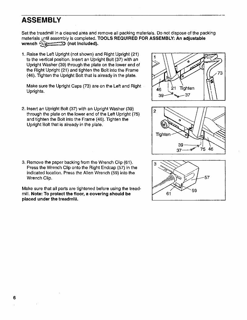
Set the treadmill in a cleared area and remove all packing materials. Do not dispose of the packingmaterials until assembly is completed. TOOLS REQUIRED FOR ASSEMBLY: An adjustable
wrench _ (not Included).
1, Raise the Left Upright (not shown) and Right Upright (21)
to the vertical position. Insert an Upright Bolt (37) with anUpright Washer (39) through the plate on the lower end ofthe Right Upright (21) and tighten the Bolt into the Frame(46). Tighten the Upright Bolt that is already in the plate.
Make sure the Upright Caps (73) are on the Left and RightUprights.
2. Insert an Upright Bolt (37) with an Upright Washer (39)through the plate on the lower end of the Left Upright (75)and tighten the Bolt into the Frame (46). Tighten theUpright Bolt that is already in the plate.
3. Remove the paper backing from the Wrench Clip (61).Press the Wrench Clip onto the Right Endcap (57) in theindicated location. Press the Allen Wrench (59) into theWrench Clip.
Make sure that all parts are tightened before using the tread-mill. Note: To protect the floor, a covering should beplaced under the treadmill.
6

OPERATION AND ADJUSTMENT
MAINTENANCE-FREE WALKING BELT
Your treadmill features a maintenance-free walking belt coated with PERFORMANT LUBE TM, a high-performance lubricant. During the first few hours of use, it is normal for a small amount of white powderto appear on the foot rails and the walking platform. The white powder is high-performance lubricantfrom the walking belt.
IMPORTANT: Never apply silicone spray or other substances to the walking belt or the walkingplatform. They will deteriorate the walking belt and cause excessive wear.
HOW TO PLUG IN THE POWER CORD
This product must be grounded. If it should malfunction or break down, grounding provides a path ofleast resistance for electric current to reduce the risk of electric shock. This product is equipped with a
cord having an equipment-grounding conductor and a grounding plug. Plug the power cord into anappropriate outlet that is properly installed and grounded in accordance with all local codesand ordinances.
DANGER: Improper connection of the equipment-grounding conductor can result in a risk
of electric shock. Check with a qualified electrician or serviceman if you are in doubt as to whether theproduct is properly grounded. Do not modify the plug provided with the product--if it will not fit the out-let, have a proper outlet installed by a qualified electrician.
This product is for use on a nominal 120-volt circuit, and has a grounding plug that looks like the plugillustrated in Drawing 1. A temporary adapter that looks like the adapter illustrated in Drawing 2 may beused to connect this plug to a 2-pole receptacle as shown in Drawing 2 if a properly grounded outlet isnot available. The temporary adapter should be used only until a properly grounded outlet (Drawing 1)can be installed by a qualified electrician. The green colored rigid ear, lug, or the like extending fromthe adapter must be connected to a permanent ground such as a properly grounded outlet box cover.Whenever the adapter is used it must be held in place by a metal screw.
Some 2-pole receptacle outlet box covers are not grounded. Contact a qualified electrician todetermine if the outlet box cover is grounded before using an adapter.
II
II
II
II
Grounded Outlet Box
Grounding Plug
nding PinGrounded Outlet
2
Lug
Metal Screw
Outlet Box
Adapter
Grounding Pin
Grounding Plug
7
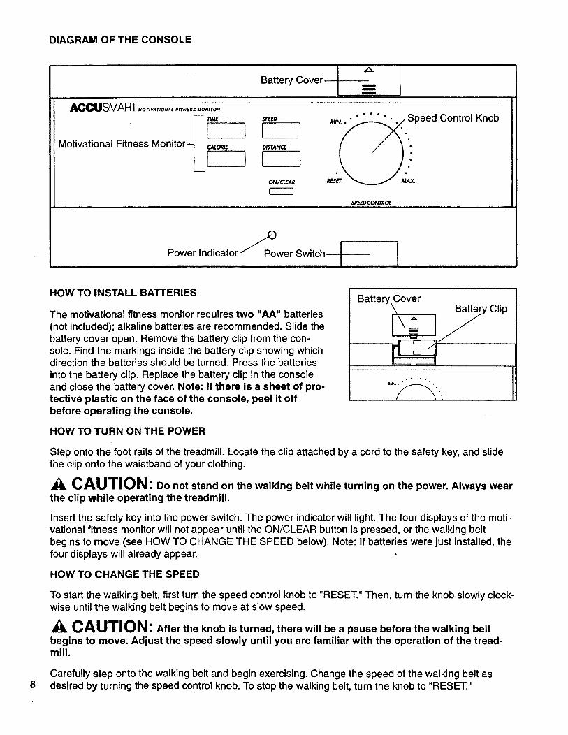
DIAGRAM OF THE CONSOLE
Battery Covermmi
IACOLISMAR-[,,o,_..,o..,.,,..,, ,,o.,,o.
Motivational Fitness Monitor: {_'Lo,,., 1
SR[ED
I J
t 1
eed..
SPEEDCONTROL
Control Knob
Power Indicator "_Power Switch ! I
8
HOW TO INSTALL BATTERIES
The motivational fitness monitor requires two "AA" batteries(not included); alkaline batteries are recommended. Slide thebattery cover open. Remove the battery clip from the con-sole. Find the markings inside the battery clip showing whichdirection the batteries should be turned. Press the batteries
into the battery clip. Replace the battery clip in the consoleand close the battery cover. Note: If there is a sheet of pro-tective plastic on the face of the console, peel it offbefore operating the console.
Battery.Cover
\ ... Battery Clip
.'''..
HOW TO TURN ON THE POWER
Step onto the foot rails of the treadmill. Locate the clip attached by acord to the safety key, and slidethe clip onto the waistband of your clothing.
CAUTION: Do not stand on the walking belt while turning on the power. Always wearthe clip while operating the treadmill.
Insert the safety key into the power switch. The power indicator will light. The four displays of the moti-vational fitness monitor will not appear until the ON/CLEAR button is pressed, or the walking beltbegins to move (see HOW TO CHANGE THE SPEED below). Note: If batteries were just installed, thefour displays will already appear.
HOW TO CHANGE THE SPEED
To start the walking belt, first turn the speed control knob to "RESET." Then, turn the knob slowly clock-wise until the walking belt begins to move at slow speed.
Ak CAUTION: After the knob is turned, there will be a pause before the walking belt
begins to move. Adjust the speed slowly until you are familiar with the operation of the tread-mill.
Carefully step ontothe walking belt and begin exercising. Change the speed of the walking belt asdesired by turning the speed control knob. To stop the walking belt, turn the knob to "RESET."

HOW TO CHANGE THE INCLINE
To vary the intensity of your exercise, the incline of thetreadmill can be adjusted using the lever on the rightupright.
Do not adjust the Incline while you are walking or run-
ning on the treadmill. To decrease the incline, standtoward the front of the foot rails, lean forward and pull upthe lever. When the desired incline is reached, release thelever. To increase the incline, stand toward the back of
the foot rails and pull up the lever. When the desiredincline is reached, release the lever.
Note: It may be helpful to step off the treadmill, pull up thelever, and lift on the handrail in order to increase the inclineof the treadmill.
InclineControl Lever
MOTIVATIONAL FITNESS MONITOR
The four displays of the motivational fitness monitor provide continuous exercise feedback. The dis-
plays can be reset by pressing the ON/CLEAR button. The four displays are described below:
TIME--This display shows the elapsed time. Note: When the walking belt is stopped, the TIME displaywill go into a pause mode after a few seconds.
CALORIE--This display shows the approximate number of nutritional Calories you have burned.
SPEED--This display shows the current speed of the walking belt, in miles per hour.
DISTANCE--This display shows the total distance that you have walked or run, in miles.
Note: If the walking belt is stopped and remains stationary for about five minutes, the four displays ofthe motivational fitness monitor will be reset and will darken, although the power will remain on. The
four displays will appear again when the ON/CLEAR button is pressed, or the walking belt is restarted.
HOW TO TURN OFF THE POWER
To turn off the power, remove the safety key from the console. The power indicator will darken. Storethe safety key in a secure location.
TROUBLE-SHOOTING AND STORAGE
Most treadmill problems can be solved by following the simple steps below. Find the symptomthat applies to your treadmill and follow the steps listed. If further assistance is needed, pleasecall our Customer Service Department toll-free at 1-800-999-3756, Monday through Friday, 6a.m. until 6 p.m. Mountain Time (excluding holidays).
1. SYMPTOM: THE POWER DOES NOT TURN ON
a. Make sure that the power cord is plugged into a properly grounded outlet. (See HOW TO PLUGIN THE POWER CORD on page 7.) If an extension cord is needed, use only a 14-gauge general-purpose cord of five feet or less in length.
b. After the power cord has been plugged in, make sure that the safety key is fully inserted into theconsole. Various indicators on the console should light. (See HOW TO TURN ON THE POWER
on page 8.)
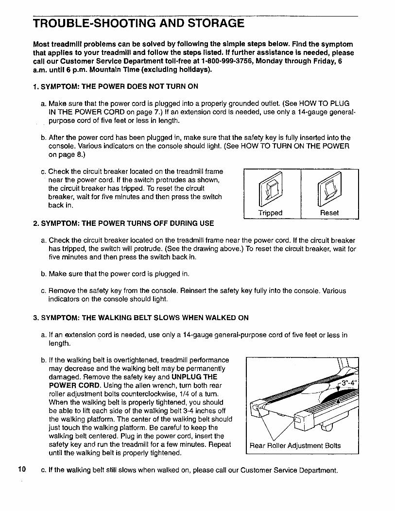
C. Check the circuit breaker located on the treadmill frame
near the power cord. If the switch protrudes as shown,the circuit breaker has tripped. To reset the circuitbreaker, wait for five minutes and then press the switchback in.
2. SYMPTOM: THE POWER TURNS OFF DURING USE
Tripped Reset
a. Check the circuit breaker located on the treadmill frame near the power cord. If the circuit breakerhas tripped, the switch will protrude. (See the drawing above.) To reset the circuit breaker, wait forfive minutes and then press the switch back in.
b. Make sure that the power cord is plugged in.
c. Remove the safety key from the console. Reinsert the safety key fully into the console. Variousindicators on the console should light.
3. SYMPTOM: THE WALKING BELT SLOWS WHEN WALKED ON
a. If an extension cord is needed, use only a 14-gauge general-purpose cord of five feet or less inlength.
b. If the walking belt is overtightened, treadmill performancemay decrease and the walking belt may be permanently
damaged. Remove the safety key and UNPLUG THEPOWER CORD. Using the allen wrench, turn both rearroller adjustment bolts counterclockwise, 1/4 of a turn.
When the walking belt is properly tightened, you shouldbe able to lift each side of the walking belt 3-4 inches offthe walking platform. The center of the walking belt shouldjust touch the walking platform. Be careful to keep thewalking belt centered. Plug in the power cord, insert thesafety key and run the treadmill for a few minutes. Repeatuntil the walking belt is properly tightened.
Rear Roller Adjustment Bolts
10 c. If the walking belt still slows when walked on, please call our Customer Service Department.
4. SYMPTOM: THE WALKING BELT IS OFF-CENTER OR SLIPS WHEN WALKED ON
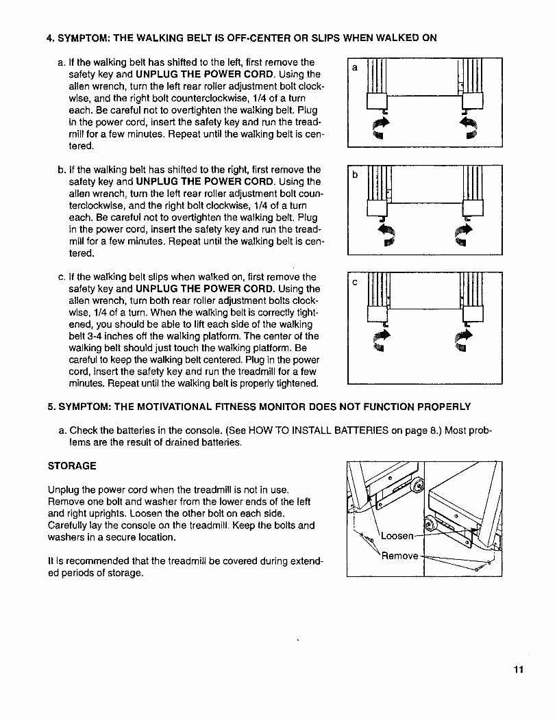
a. If the walking belt has shifted to the left, first remove thesafety key and UNPLUG THE POWER CORD. Using theallen wrench, turn the left rear roller adjustment bolt clock-
wise, and the right bolt counterclockwise, 1/4 of a turneach. Be careful not to overtighten the walking belt. Plugin the power cord, insert the safety key and run the tread-mill for a few minutes. Repeat until the walking belt is cen-tered.
a
b. If the walking belt has shifted to the right, first remove thesafety key and UNPLUG THE POWER CORD. Using theallen wrench, turn the left rear roller adjustment bolt coun-terclockwise, and the right bolt clockwise, 1/4 of a turn
each. Be careful not to overtighten the walking belt. Plugin the power cord, insert the safety key and run the tread-mill for a few minutes. Repeat until the walking belt is cen-tered.
C. If the walking belt slips when walked on, first remove thesafety key and UNPLUG THE POWER CORD. Using theallen wrench, turn both rear roller adjustment bolts clock-wise, 1/4 of a turn. When the walking belt is correctly tight-ened, you should be able to lift each side of the walkingbelt 3-4 inches off the walking platform. The center of thewalking belt should just touch the walking platform. Becareful to keep the walking belt centered. Plug in the powercord, insert the safety key and run the treadmill for a fewminutes. Repeat until the walking belt is properly tightened.
5. SYMPTOM: THE MOTIVATIONAL FITNESS MONITOR DOES NOT FUNCTION PROPERLY
a. Check the batteries in the console. (See HOW TO INSTALL BATTERIES on page 8.) Most prob-lems are the result of drained batteries.
STORAGE
Unplug the power cord when the treadmill is not in use.Remove one bolt and washer from the lower ends of the left
and right uprights. Loosen the other bolt on each side.Carefully lay the console on the treadmill. Keep the bolts andwashers in a secure location.
It is recommended that the treadmill be covered during extend-ed periods of storage.
11

CONDITIONING GUIDELINES
The following guidelines will help you to plan your exercise program. Remember that proper nutritionand adequate rest are essential for successful results.
WARNING: Before beginning this or any exercise program, consult your physician.
This is especially Important for individuals over the age of 35 or individuals with pre-existinghealth problems.
EXERCISE INTENSITY
To maximize the benefits of exercising, it is important to exercise with the proper intensity. The properintensity can be found by using your heart rate as a guide. For effective aerobic exercise, your heartrate should be maintained at a level between 70% and 85% of your maximum heart rate as you exer-cise. This is known as your training zone. You can find your training zone in the table below.Training zones are listed for both unconditioned and conditioned persons according to age.
UNCONDITIONED CONDITIONEDTRAINING ZONE TRAINING ZONE
AGE (BEATS/MIN) (BEATS/MIN)
20 138-167 133-162
25 136-166 132-160
30 135-164 130-158
35 134-162 129-156
40 132-161 127-155
45 131-159 125-153
50 129-156 124-150
UNCONDITIONED CONDITIONEDTRAINING ZONE TRAINING ZONE
AGE (BEATS/MIN) (BEATS/MIN)
55 127-155 122-149
60 126-153 121-147
65 125-151 119-145
70 123-150 118-144
75 122-147 117-142
80 120-146 115-140
85 118-144 114-139
12
During the first few months of your exercise program, keep yourheart rate near the low end of your training zone as you exercise.After a few months, your heart rate can be increased graduallyuntil it is near the middle of your training zone as you exercise. Tomeasure your heart rate, stop exercising and place two fingers onyour wrist. Take a six-second heartbeat count, and multiply theresult by 10 to find your heart rate. For example, if your six-secondheartbeat count is 14, your heart rate is 140 beats per minute. (A
six-second count is used because your heart rate will drop rapidlywhen you stop exercising.) Adjust the intensity of your exerciseuntil your heart rate is at the proper level.
WORKOUT GUIDELINES
Each workout should consist of three basic parts: a warm-up, 20 to 30 minutes of training zone exer-cise, and a cool-down. Warming up prepares the body for exercise by increasing circulation, deliveringmore oxygen to the muscles and raising the body temperature. Begin each workout with 5 to 10 min-utes of stretching and light exercise to warm up. Then, increase the intensity of your exercise to raiseyour heart rate to your training zone for 20 to 30 minutes. Breathe regularly and deeply as you exer-cise--never hold your breath. Finish each workout with 5 to 10 minutes of stretching to cool down. Thiswill increase the flexibility of the muscles, and reduce soreness and other post-exercise problems.
To maintain or improve your condition, complete three workouts each week, with at least one day ofrest between workouts. After a few months of regular exercise, you may complete up to five workoutseach week, if desired. The key to success is CONSISTENCY.
SUGGESTED STRETCHES
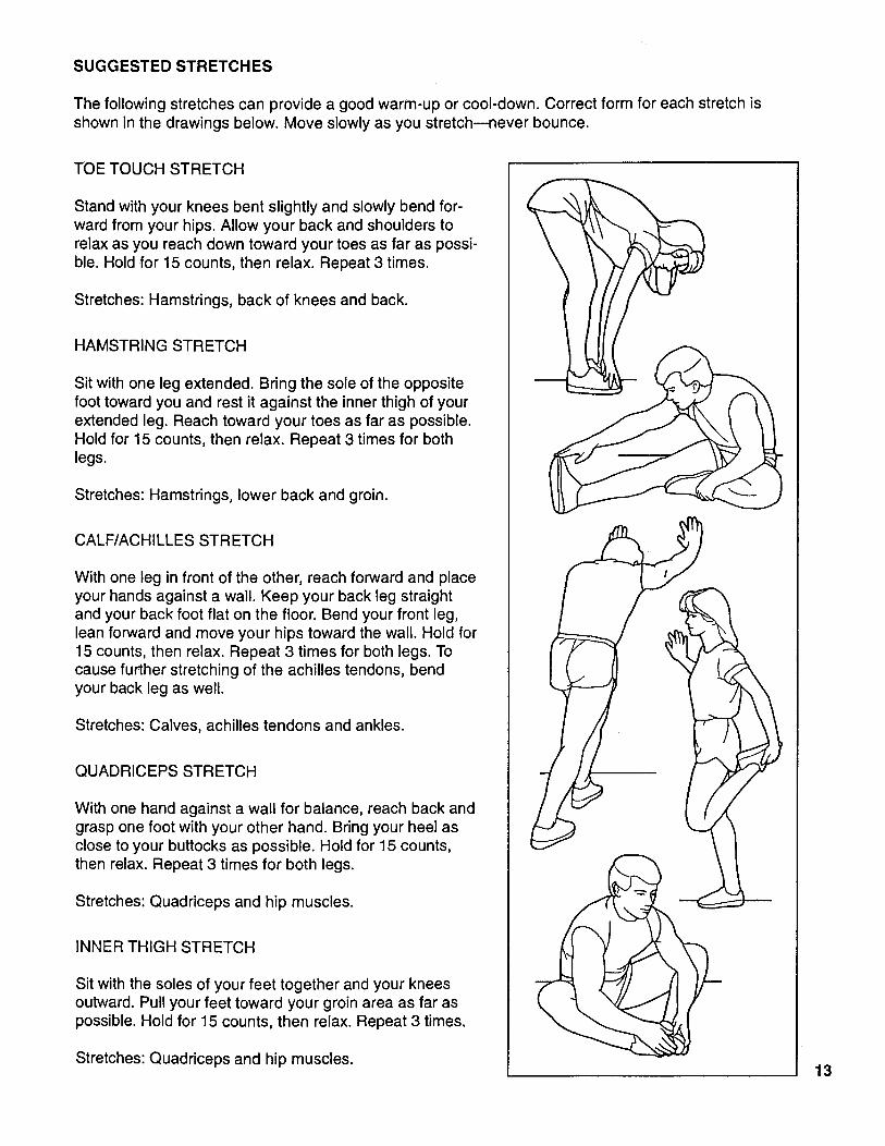
The following stretches can provide a good warm-up or cool-down. Correct form for each stretch is
shown in the drawings below. Move slowly as you stretch--never bounce.
TOETOUCH STRETCH
Stand with your knees bent slightly and slowly bend for-ward from your hips. Allow your back and shoulders torelax as you reach down toward your toes as far as possi-ble. Hold for 15 counts, then relax. Repeat 3 times.
Stretches: Hamstrings, back of knees and back.
HAMSTRING STRETCH
Sit with one leg extended. Bring the sole of the oppositefoot toward you and rest it against the inner thigh of yourextended leg. Reach toward your toes as far as possible.Hold for 15 counts, then relax. Repeat 3 times for bothlegs.
Stretches: Hamstrings, lower back and groin.
CALF/ACHILLES STRETCH
With one leg in front of the other, reach forward and placeyour hands against a wall. Keep your back leg straightand your back foot flat on the floor. Bend your front leg,lean forward and move your hips toward the wall. Hold for15 counts, then relax. Repeat 3 times for both legs. Tocause further stretching of the achilles tendons, bendyour back leg as well.
Stretches: Calves, achilles tendons and ankles.
QUADRICEPS STRETCH
With one hand against a wall for balance, reach back andgrasp one foot with your other hand. Bring your heel asclose to your buttocks as possible. Hold for 15 counts,then relax. Repeat 3 times for both legs.
Stretches: Quadriceps and hip muscles.
INNER THIGH STRETCH
Sit with the soles of your feet together and your kneesoutward. Pull your feet toward your groin area as far aspossible. Hold for 15 counts, then relax. Repeat 3 times.
Stretches: Quadriceps and hip muscles.
\
13

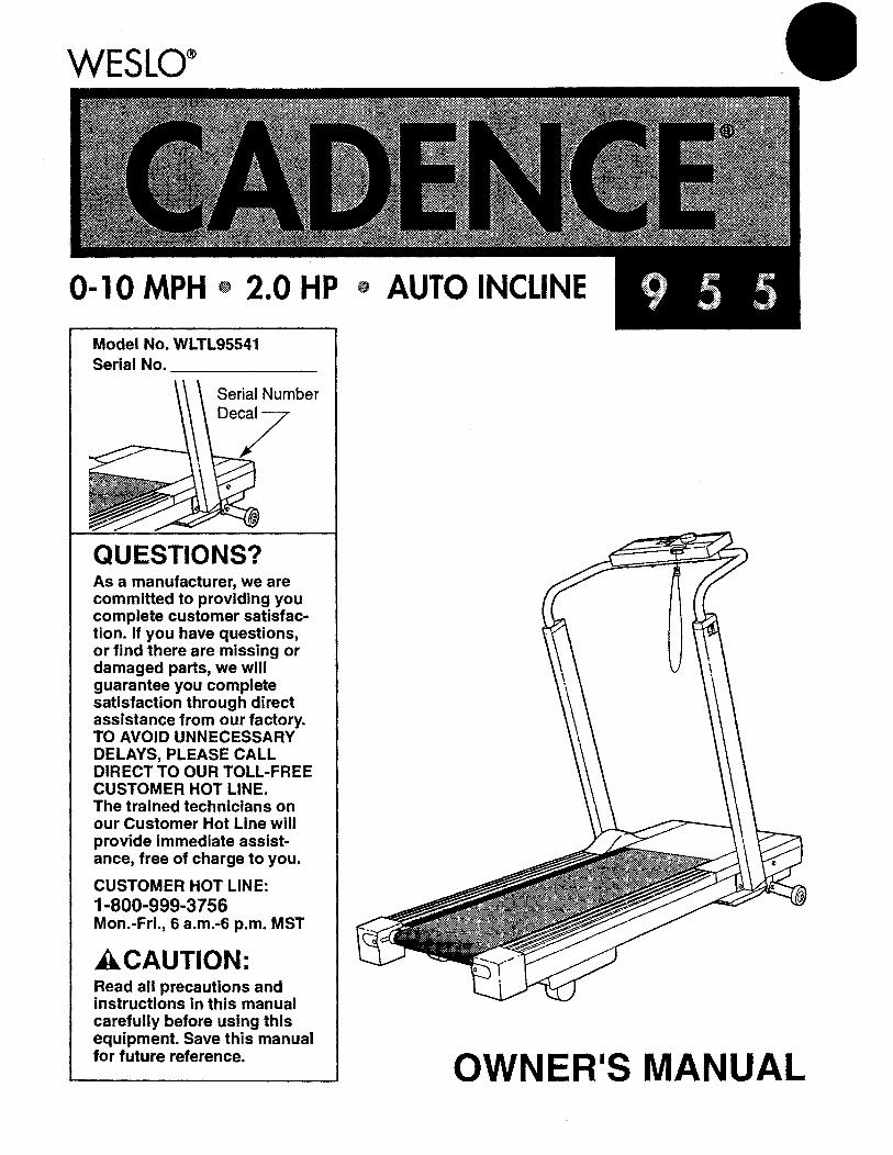
PART LIST---Model No. WLTL95541 R695A
Key KeyNo. Qty. Description No. Qty. Description
1 1 Left Handrail 49 2 Motor Bolt2 6 Handrail/Upright Cage Nut 50 1 Controller3 2 Console Bolt 51 2 Motor Swivel Bolt4 1 Safety Key/Clip 52 1 Choke5 1 Console 53 1 Motor6 4 Console Screw 54 2 Motor Nut7 1 Console Plate 55 1 Pulley/Flywheel/Fan8 1 Speed Control Knob 56 1 Hood Rest Pad9 1 Incline Control Cable 57 1 Right Endcap10 1 Shock Release 58 2 Rear Roller Adjustment Bolt11 1 E-Clip 59 1 Allen Wrench12 1 Shock Bracket 60 -1 Left Endcap13 1 Shock Spacer 61 2 Wrench Clip14 1 Incline Shock 62 1 Rear Roller15 1 Cotter Pin 63 2 Roller Guard16 1 Right Handrail 64 6 Platform Screw17 4 Handrail Bolt 65 1 Motor Hood
18 2 Plastic Spacer 66 1 Reed Switch/Lower Sensor Wire19 1 Shock Pin 67 1 Magnet20 1 Incline Control Lever 68 1 Belt21 1 Right Upright 69 1 Wire Clip22 2 Ground Washer 70 1 Tension Spring23 4 Small Screw 71 4 Tension Washer/Swivel Washer24 1 Power Cord 72 7 Lock Nut25 1 Circuit Breaker 73 2 Upright Cap26 11 Silver Screw 74 1 Incline Leg27 5 Hood Anchor 75 1 Left Upright28 1 Grommet 76 1 Electronics Bracket29 10 Safety Cover Screw 77 2 Cushion Cover30 1 Front Roller Adjustment Bolt 78 1 12" Cable Loom31 2 Roller Adjustment Washer 79 1 6" Cable Loom32 2 Front Wheel 80 1 Ground Wire33 2 Incline Leg Nut 81 1 Power Switch Wire34 9 Screw 82 1 Reed Switch Extension Wire35 2 Front Wheel Bolt 83 1 Reed Switch Mounting Bracket36 2 Incline Leg Bolt 84 1 Cable Tie Wrap37 4 Upright Bolt 85 1 Tie Block38 1 Hood Support Bracket 86 3 4" Cable Tie39 6 Upright Washer/Leg Washer 87 4 8" Cable Tie40 1 Front Roller Tab 88 2 Foam Block
41 1 Safety Cover 89 4 Cushion Spring Bolt42 1 Front Roller/Pulley 90 2 Cushion Spring Foot43 1 Walking Platform 91 1 Belt Guide44 1 Walking Belt 92 2 Star Washer45 2 Foot Rail 93 4 Cage Nut46 1 Frame 94 3 Belt Guide Screw47 1 J-Bolt 95 5 Mounting Screw48 1 Motor Swivel Shaft # 1 Owner's Manual
14Note: "#" indicates a non-illustrated part. Specifications are subject to change without notice. See the
back cover for information about ordering replacement parts.
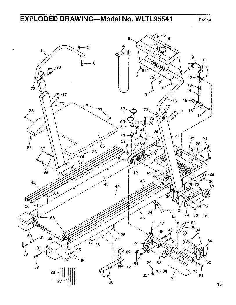
EXPLODED DRAWING--Model No. WLTL95541 R69SA
73
23
88 3723
88
65
¢'/ 7
8
! 10
11
12
i!!!!I
16
82-.,._ 20 ,17 1 i
66 71 / "/"
61 _95 "1"/"1 /"
83 11 ! 95 24
! 26
25
45\
31
59
58
39
43 44
/
42 41
45
32
80
15

ORDERING REPLACEMENT PARTS
To order replacement parts, call our Customer Service Department toll-free at 1-800-999-3756,
Monday through Friday, 6 a.m. until 6 p.m. Mountain Time (excluding holidays). When ordering parts,please be prepared to give the following information:
• The MODEL NUMBER of the product (WLTL95541).
• The NAME of the product (WESLO CADENCE ®955 treadmill).
• The SERIAL NUMBER of the product (see the front cover of this manual).
• The KEY NUMBER of the part(s) from page 14 of this manual.
• The DESCRIPTION of the part(s) from page 14 of this manual.
If possible, place the treadmill near your telephone for easy reference when calling.
Part No. 123240 R695A Printed in USA © 1995 ICON Health & Fitness, Inc.