Embed Size (px)
Citation preview

…wenn es um Qualität geht! BMR GmbH
1

2 SFU 1000 Frequenzumrichter
Issue November 2021 Rev. 1.0
1 Description and Features 3
2 Technical Data 4
3 Intended use / Safety instructions and warnings 5
4 Connections, Interfaces and Pinout 6
5 Functional description, commissioning, operation 11
4.1 X1 Spindle-Power Supply 7 4.2 X2 Logic-Power Supply 7 4.3 X3 STO-Function 7 4.4 X4 Digital Inputs 8 4.5 X5 Analog In- and Outputs 8 4.6 X6 Digital Outputs 9
4.7 Serial Interface 9
4.7.1 X7 RS232 9
4.7.2 X8 USB 9
4.8 X9 Spindle Sensor Interface 10
4.9 X10 Spindle Connection 10
5.1 Spindle Characteristics / Spindle Diagrams 11 5.2 Start and Stopp 12 5.3 Setup of Rotational Speed 12 5.4 Inputs 13 5.4.1 Digital Inputs 13 5.4.2 Safe Torque Off 13 5.4.3 Analoge Inputs 13 5.5 Outputs 14 5.5.1 Digital Outputs 14 5.5.2 Relay Output 14 5.5.3 STO Feedback Relay 14 5.5.4 Analog Outputs 14 5.5.5 Reference Voltage Output +10V URef 14 5.6 LEDs 15 5.7 Overload Function: I2T 16

…wenn es um Qualität geht! BMR GmbH
3
1. Description and Features
✓ Operation of Asynchronous-AC und Synchronous-BLDC Motors
✓ Very compact size for various mounting types such as control cabinet mounting and more
✓ The high frequency converter SFU-0303 makes possible output frequencies 4000Hz/240.000 rpm
✓ with 2pole AC-Motors and with BLDC-Motors up to 1667Hz/100.000 rpm. The core of SFU-0303 is a Digital Signal Processor (DSP) which produces all output signals and collects all input signals.
✓ High precision sinusoidal output signals with low distortion factor realize very high accuracy and running behavior with AC-motors.
✓ All parameters like current, voltage and frequency are captured in real time and are regulated by the implemented vector control depending on the load condition.
✓ Allows highest efficiency of the spindles at low and high frequencies
✓ High operational safety: All operating conditions like acceleration, operation with nominal rotational speed, deceleration are monitored and critical conditions are intercepted.
✓ Short Circuit Proof by DSP-supervision
✓ Integrated Brake Chopper Resistor
✓ Overtemperature protection by DSP-supervision
✓ Integrated intelligent recovery diode prevents overvoltage at the power supply
✓ STO Function for highest safety at standstill and protection against unintended starting
✓ Overload control selectable either by time control or by I2T
7 Safety Precautions and Warnings 17
8 EMC 21
10 Dimension and Mechanic 23
6 Connection I/O 16
7.1 Safety Functions 17 7.2 Safe Torque Off (STO) 18 7.2.1 General Description STO 18 7.2.2 Function STO 19
7.2.3 Timing STO 20
9 Power Supply 22

4 SFU 1000 Frequenzumrichter
2. Technische Daten
Spindle: max. 85V / 12A DC - pluggable screw terminals 4Pin-2,5mm²
Logic: 24V / 0,1 A DC (20V…30V) - plugable screw terminals 3Pin-1,5mm²
Fuses FS1/FS2 internal T12A / T500mA
Output Power
Spindle Connection U, V, W, PE - pluggable screw terminals 4Pin-2,5mm²
Output Voltage max. 55 VAC
Output Current Imax continuous phase current 12A / peak phase current 15A
AC-Spindle: f = 4.000 Hz / max. 240.000 rpm
DC-Spindle: f = 1.667 Hz / max. 100.000rpm
4 x freely programmable ( 0 / 24V ) "0": 0..7V, "1": 18..24V
pluggable screw terminals 6Pin-1,5mm²
2 x freely programmable ( 0..10V )
pluggable screw terminals 6Pin-1,5mm²
at pluggable screw terminals 2,5mm²
Relay 1 x change over contacts (NO/NC), freely programmable
3 x freely programmable ( 0 / 24V ) je 10mA max
at pluggable screw terminals 1,5mm²
2 x freely programmable (0…10V)
at pluggable screw terminals 7 x 1,5mm²
Uref +10V Ref / 100mA Reference Voltage for Analog-In
Uh +24V
STO-channel A, STO-chanel B: ( 0 / 24V ) for power stage release
STO-Monitor Relay (normally open) for status feedback
at pluggable screw terminals 7 x 1,5mm²
LED green: Ready and indication of rotational speed
LED red: Indication of errors and warnings
LED yellow: STO-Status
Interfaces RS232 Interface: Dsub9male ( 115.200Bd, 8 Data 1 Stop Bit, No Parity )
USB Interface: USB-Mini
Dimensions (L x B x H) 175,5 x 126,5 x 32 mm
Brake Chopper 47Ohms / 10W
Operating Conditions 5°C to 40°C / Humidity max. 85%
Power Supply
Temperature Sensor: PTC, KTY or PT1000
Speed Sensor: Magneto Resistor
Control Inputs
Digital In:
Analog In:
Digital Out:
Analog Out :
Safety Functions
"Safe Torque Off"STO
1080VA / S1 100% 1350VA / max.
Operation Displays
Output Frequency
Auxilary Voltages
Spindle-Sensor Inputs
Control Outputs

…wenn es um Qualität geht! BMR GmbH
5
3. Intended Use / Safety Instructions and Warnings
✓ This unit is designed for operation in industrial environments only. When used in residential and commercial areas, additional measures may be required to limit the emitted interference
✓ Applicable safety regulations must be observed during installation.
✓ Before switching on the inverter for the first time, make sure that it is fixed and that the connected spindle is also securely fixed and cannot make any uncontrolled movements.
✓ Compliance with EMC (Electro Magnetic Compatibility) limits is the responsibility of the manufacturer of the machine or device. The inputs and outputs of this unit are equipped with filters to increase immunity to interference and reduce emitted interference. This means that operation in an industrial environment is generally possible.
✓ The EMC of a machine or appliance is influenced by all connected components (motor, cables, wiring, ...). Under certain conditions, the connection of external filters may be necessary to ensure compliance with the applicable EMC standards.
✓ This unit generates dangerous electrical voltages and is used to operate dangerous rotating mechanical tools. For this reason, only professionally qualified, trained personnel may work on this appliance and make the connection!
✓ Before putting the unit into operation, make sure that it is in perfect condition. If it has been damaged during transport, it must not be connected under any circumstances.
✓ The inverter must not be operated in the vicinity of heat sources, strong magnets or devices generating strong magnetic fields.
✓ Sufficient air circulation at the inverter must be ensured. The heat sink must not be covered.
✓ Do not allow any liquid to enter the unit. If this appears to be the case, the appliance must be switched off and disconnected from the mains.
✓ The ambient air must not contain any aggressive, highly flammable or electrically conductive substances and should be as free of dust as possible.
✓ All work on the inverter and the corresponding accessories may only be carried out when it is switched off and disconnected from the mains. The national accident prevention regulations as well as the general and regional assembly and safety regulations (e.g. VDE) must be observed.
✓ All work in connection with one of our inverters may only be carried out by persons who are professionally qualified and have been instructed accordingly.
ATTENTION Please ensure to have the proper characteristic selected, always! The operation of a spindle with a wrong characteristic may harm the spindle severely!
ATTENTION Please verify that all power supply voltages are correct in polarity and value.

6 SFU 1000 Frequenzumrichter
4. Connections, Interfaces and Pinouts
X1 Mains Power Supply for Spindle and Logic
LEDs
X5 Analog In/Out
X7 RS232
X4 Digital In
X8 USB
X3 STO
X6 Digital Out
X2 Logic Power Supply
X10 Spindle Connection
X9 Spindle Interface

…wenn es um Qualität geht! BMR GmbH
7
4.1 X1 Mains-Power Supply (pluggable screw terminals RM5,08mm / up to 2,5mm2 )
Pin Function Description
1 PE Protective Earth, internally connected with mounting plate
2 NC not connected
3 +85VDC max Power Supply Spindle and Logic ( Fuse FS2 12A )
4 GND Power Supply0V (85V)
PT1000
Before switching on the power supply, please ensure that the polarity of the connection is wired correctly! There is no protection against polarity errors. Reversing the polarity will damage the unit! When a voltage is connected to Pin3-4, the +24V logic voltage for the digital/logic part is automatically generated. With this, the inverter is in function. Switching it off also deactivates the digital/logic part. If this is not desired, the digital part can also be supplied separately externally via X2.
4.2 X2 Logic-Power Supply (pluggable screw terminals RM3,5 mm / up to 1,5mm2)
Pin Function Description
1 +20V … +30V Digital/Logic Power Supply
2 GND GND Digital/Logic Power Supply
3 PE Protective Earth, internally connected with mounting plate
With the connection of a voltage of +20V to +30V, only the digital part of the SFU 1000 is put into operation. This makes it possible to read out and configure the inverter. A spindle cannot be started now.
4.3 X3 STO-Function (pluggable screw terminals RM3,5 mm / up to 1,5mm2)
Pin Function Description
1 Relay Contact 2.1 Relay Contact 2.1
2 Relay Contact 2.2 Relay Contact 2.2
3 GND-STO-B Ground STO-Channel B
4 STO-B STO-Kanal B
5 GND-STO-A Ground STO-Channel A
6 STO-A STO-Kanal A
The ground potentials are separated from each other and from the spindle and logic ground. Relay contact2 is only used to check the STO status, but must not be used for safety-related functions. Relay contact2 is closed when a +24V signal is applied to channel A and B, thus unlocking the STO function. The power stage of the inverter is now ready for operation. (→ 7.2) Both the scaling of the analogue value and the assignment of the output functions to the digital outputs can be done freely. The functions in bold are the delivery settings

8 SFU 1000 Frequenzumrichter
4.4 X4 Digital-Inputs (pluggable screw terminals RM3,5 mm / up to 1,5mm2)
Pin Function Description
1 Digital Input1 Default Setting: Start / Stopp, freely programmable
2 Digital Input2 freely programmable
3 Digital Input3 freely programmable
4 Digital Input4 freely programmable
5 +24V UH Auxillary Voltage (10mA max.)
6 GND Reference-GND for Pin 1,2,3,4 Digital Inputs and Pin5 UH.
✓ Switch level Digital Inputs: Log"0" = 0…7V / Log"1" = 13….24V PLC standard level ✓ Pin6 is connected with all GND potentials. ✓ Special care is required when using and wiring the auxiliary voltage and is on the responsibility
of the user! The voltages are not fused. Possible connection errors can lead to damage to the device
Shown here as an example, the input stage of a digital input
4.5 X5 Analog-Inputs and Outputs (pluggable screw terminals RM3,5 mm / up to 1,5mm2)
Pin Function Description
1 Analog Input 1 default setting: Reference Value Duty Speed, Function freely programmable
2 Analog Input 2 Function freely programmable
3 Analog Output default setting: Load Percent , Function freely programmable
4 GND Reference-GND for Pin 1, 2, 3, 6
5 GND Reference-GND for Pin 1, 2, 3, 6
6 +10V URef Auxillary Reference Voltage +10V ( 100mA max.)
✓ Analog Voltage Range: 0…10V ✓ Pin4 and 5 are connected with all GND Potentials, unless otherwise stated
✓ With a connection of a potentiometer between pin6 and pin5, a speed setting can be tapped directly at the wiper.
Shown here as an example, the input stage of an analog input
4.6 X6 Digital- Outputs (pluggable screw terminals RM3,5 mm / up to 1,5mm2)

…wenn es um Qualität geht! BMR GmbH
9
Pin Function Description
1 Relay Contact 1.1 D-Out 1: (normally open)
2 Relay Contact 1.C D-Out 1: (Common) default setting: Converter Ready ( freely programmable)
3 Relay Contact 1.2 D-Out 1: (normally closed)
4 Digital Out 2 default setting: Standstill freely programmable)
5 Digital Out 3 default setting: Duty Speed reached (freely programmable)
6 Digital Out 4 default setting: Overload (freely programmable)
7 GND Reference Ground for Pin 4,5,6
✓ Der Ausgangspegel für Digital Out 2,3,4 beträgt 0 und +24V und kann je bis zu 25mA liefern
4.7 Serial Interface
✓ With the help of the PC program SFU-Terminal, the SFU 1000 can be configured and controlled very easily via the serial interface.
✓ The program is freely available on the BMR homepage, and is very helpful in configuring and commissioning the inverter.
✓ A manual for it is available on the website as a PDF. ✓ The command set for the control commands is freely available as a download on the BMR homepage.
✓ Attention: Since the serial interface X7:RS232 shares the internal connection with the X8:USB interface, the connections can only be used alternatively.
4.2.1 X7 RS232 (D-Sub9-male)
Pin Function
1, 4, 6, 7, 8 NC
2 RxD
3 TxD
5 GND
For communication via the RS232 interface with a PC, a null modem cable with crossed RxD and TxD lines can be used.
4.2.2 X8 USB-Connection (USB Mini)
The SFU 1000 is equipped with an USB-Interface via a USB-Mini connector.

10 SFU 1000 Frequenzumrichter
4.8 X9 Spindle Interface (pluggable screw terminals RM3,5 mm / up to 1,5mm2)
Pin Function Description
1 Speed Sensor For connection with a Magneto Resistor (Field Plate)
2 Temp Sensor For connection with the spindle temperature sensor: PTC, KTY, PT1000
3 Spindle GND Reference-GND for Pin 1, 2
With the configuration program SFU-Terminal, it is very easy to activate and deactivate the speed sensor and the temperature sensor. Equally the type of temperature sensor type can be selected.
4.9 X10 Spindle Connection (pluggable screw terminals RM5,08mm / up to 2,5mm2)
Pin Function Description
1 W Spindle Phase W
2 V Spindle Phase V
3 U Spindle Phase U
4 PE Connection for spindle PE and shielding of spindle cable
ATTENTION Please verify that all power supply voltages are correct in polarity and value !
ATTENTION After the first test, please check whether the direction of rotation is correct! If necessary, adjust the direction of rotation by exchanging the motor phases or by configuring the direction of rotation using the SFU terminal !

…wenn es um Qualität geht! BMR GmbH
11
5. Functional description, commissioning, operation
5.1 Spindle Charactreistics or Spindle Diagrams
All converters of BMR need an information about the basic data of the spindle, such as maximum voltage, current, rotational speed, and many more. These are stored in so called "Spindle Characteristic" or "Spindle Diagram". A BMR spindle characteristic has 16 setpoints within the range of the rotational speed. At every point data of voltage, current, load scaling, acceleration and deceleration ramp and many more data can be defined and this for idle load as well as for full load. And there are in total 16 places for different characteristics. The spindle characteristics are the key for any spindle and give a possibility to control the running behavior at every load condition.
In advance of starting a spindle first, it has to be ensured, that the proper characteristic is selected
and activated. This is generally the case, if the converter is delivered together with a spindle/motor and the required setup is already done. If the converter and spindle are delivered separately, the proper spindle characteristic has to be loaded into the converter first. This can be achieved with the free setup software SFU-Terminal, easily. In case of being unsure, characteristics for most common spindles are available at BMR.
The spindle characteristics can be selected in the project file ( * .ps5 ) . Spindle characteristics are created by BMR and can be loaded and managed using the program SFU - Terminal.
ATTENTION Please ensure to have the proper characteristic selected, always! The operation of a spindle with a wrong characteristic may harm the spindle severely!

12 SFU 1000 Frequenzumrichter
5.2 Start / Stop
The spindle can be started in three ways: digitally with a control signal at the digital input with the start/stop function. The switching thresholds are 0...7V for "OFF=0" and 18...24V for "ON=1", Voltage levels between 7V and 18V are not defined. ➔ As soon as the start has been triggered, the spindle is accelerated to the setpoint value which
is set at the analogue input with the function Reference Value Duty Speed by a corresponding voltage.
➔ The scaling for this is adjustable: - 1V/1.000Upm for fine resolution in the lower speed range - 1V/10.000Upm as standard setting - 0-10V/Min-Max for using the full resolution oft he control range
✓ analog with a voltage at the analog input
For this purpose, a valid "ON" level must be applied to the input with the Start/Stop function.. ➔ a voltage greater than 0.29V starts the spindle from the min speed up to the speed according
to the scaling ➔ An input voltage of 0V leads to a standstill of the spindle
✓ Serially via interface and control commands The command set for the control commands is freely available as a download on the BMR homepage. Since the serial interface X7:RS232 shares the internal connection with the X8:USB interface, the connections can only be used alternatively..
5.3 Setup of Rotational Speed
There are three possibilities for scaling the speed:
✓ 1V/1.000Upm: here, the control voltage directly maps the speed. In this scaling, fine adjustment is possible in the lower speed range. This is not suitable for higher speeds. At a minimum speed of 5,000 rpm, the minimum start voltage is > 5 V.
✓ 1V/10.000Upm: here, the control voltage maps the speed directly and is thus very easy to scale. However, the resolution of the speed in the voltage value is reduced for speed ranges up to 100,000. At a minimum speed of 5,000 rpm, the minimum start voltage is > 0.5 V.
✓ 0-10V / Min-Max: The scaling for the analogue value corresponds to the min. and max. values of the speed from the spindle characteristic curve. This means, that the full range of the resolution can always be used. Basic values e.g.: Min: 5,000 rpm, Max: 60,000 rpm. This results in the control voltage U= target speed * 10V/60000Upm A voltage of U < 0.8V is standstill, a voltage of 0.8V sets the minimum speed of 5,000 rpm. of 5,000 rpm, and 10V sets a speed of 60,000 rpm.

…wenn es um Qualität geht! BMR GmbH
13
5.4 Inputs
5.4.1 Digital Inputs at pin-connector X4.1, X4.2, X4.3, X4.4
4 digital inputs are available for controlling the inverter. These can be freely configured for 3 functions. Further functions are in preparation - Converter Start/Stop - Emergency Stop / Locking - Reversing direction of Rotation The switching thresholds are 0...7V for "OFF=0" and 18...24V for "ON=1", Voltage levels between 7V and 18V are not defined.
5.4.2 Safe Torque Off (STO) Function at pin-connector X3.3, X3.4 STO-A / X3.5, X4.6 STO-B When not switched on, the STO function is activated and the output stage is deactivated. To enable the output stage, both control inputs STO-A and STO-B must be connected to +24V. (→ 7.2)
5.4.3 Analog Inputs at pin-connector X5.1, X5.2
2 analogue inputs (0...10V) are available for controlling the inverter and specifying setpoint and reference values. These can be freely configured for 2 functions. - Reference Value Duty Speed - Reference Value Varioload
Varioload is a freely definable switching threshold in the range of 0-100% for the load current. The scaling for this is fixed at 1V/10%. Thus, the range 0-100% covers the voltage range 0 to 10V. This threshold can be set up as a fix value in the SFU terminal or variably set via an analogue input. When this threshold is reached, the Varioload parameter is set to "1". A digital output can be assigned to this parameter for feedback to the controller. The StatusFlags can be checked in the debug tool of the SFU terminal. The following examples can be seen as an application for this:
✓ For example, monitoring the cutting power of the tool. Since the load current of the spindle typically maps the machining process directly, an increasing current can be seen as an indicator for the degree of wear of a tool. Above a certain value, it can be determined when the tool is worn and needs to be changed. With this, the quality and surface finish of the machining can be kept constant and unplanned tool breakage can also be prevented.
✓ Or tool breakage detection. A certain machining process always requires a certain load current. If this is suddenly undershot and no longer reached, a tool breakage can be assumed and the control can trigger a warning message for this.

14 SFU 1000 Frequenzumrichter
5.5 Outputs 3 digital outputs and a potential-free relay with changeover contact are available as feedback to the PLC or another control system. They are freely configurable and can be assigned to different inverter messages. The most important are listed here: - Converter Ready - Overload Spindle - Duty Speed Converter Reached - Duty Speed Spindle Reached - Standstill Converter - Standstill Spindle - Overtemperature Spindle - And many more (all functions are mapped in the SFU terminal)
5.5.1 Digital Outputs: at pin-connector X6.4, X6.5, X6.6
The switching thresholds are 0V for "OFF=0" and +24V for "ON=1", They can each be loaded up to 10mA.
5.5.2 Relay Output: at pin-connector X6.1/K1-NO, X6.2/K1-C, X6.3/K1-NC
Potential-free to inverter ground (GND) and (PE) with dielectric strength of 1500V AC. The contacts can be loaded with the following values: 30V DC / 1A or 125V AC / 0.3A
5.5.3 STO- Feedback Contact at pin-connector X3.1-K2.1, X3.2-K2.2
Is open, when STO is active → the inverter is disabled (→7.2)
5.5.4 Analog Output: at pin-connector X5.3 An analogue output is available for feedback to the PLC or another control system. This is freely configurable and can be assigned to different inverter parameters. In the default setting, the current active load% is output as a voltage between 0...10V at the analogue output X5.3 in a scaling of 1V/10%. Other configurations are possible.
5.5.5 Auxillary Reference Voltage Output +10V URef at pin-connector X5.6 A +10V reference voltage is available here. This can be used to set a preset speed value with the help of a potentiometer. The +10V output is short-circuit proof and rated for a maximum current of 100mA. A continuous short circuit is not permissible and will damage the inverter. It is the user's responsibility to prevent this..

…wenn es um Qualität geht! BMR GmbH
15
5.6 LED‘s The current status of the SF1000 is indicated by the LEDs
LED 1 green LED 2 red Message
ON OFF Converter Standstill - No Error
Flashing quickly OFF Converter is accellerating the spindle- No Error
Flashing OFF Duty Set Value rot. Speed reached - No Error
Flashing ON Speed reached - Overload spindle - switch-off delay time is running (1)
ON ON Overload spindle - switched off after switch-off delay time has elapsed (1)
ON Flashing No spindle / cable breakage - testing of spindle phases with error (2)
ON Flashing quickly Power stage switched off -Instant switch off due to reaching current threshold (3)
ON Flashing long-short Immediate switch off: Back energy of spindle too high during ramp down (5)
OFF Flashing Overtemperature SFU - switched off after switch-off delay time has elapsed (6)
Flashing Flashing With DC-spindleMit Synchron Spindel: Stall Error, spindle could not start up (7)
(1) Überlast Spindel: (Ansprechschwelle abhängig von Spindel Kennlinie)
(2) Es werden alle drei Ausgangsphasen mit einer Prüfspannung getestet
Fehler, falls eine oder mehrere Phasen auf Prüfspannung keine Stromantwort liefern
(3) Abschaltstrom für Endstufenschutz: 12A Max
(4) Einsatzspannung Bremschopper: 88V
(5) Abschaltspannung bei Rückenergie: 95V
Falls beim Runterrampen die Rückspannung von der Spindel 95V übersteigt
(6) Fehler-Schwelle Übertemperatur Endstufe: 70°C
(6) Fehler Reset Übertemperatur Endstufe: 67°C
(7) Stall-Fehler: Rotor folgt nicht dem magnetischem Feld: Beim Anlauf oder unter Last
Status LED 1 Gelb LED 2 Rot Meldung
Error-Stillstand EIN EIN STO-Funktion aktiv: Umrichter ist gesperrt (8)
Error-Stillstand Blinkt EIN STO-Error: ungleiche Pegel and den STO-Kanälen: Umrichter ist gesperrt (9)
(8) STO aktiv: Die Endstufe des Umrichters ist solange gesperrt, bis an beiden STO-Kanälen 24V angelegt wird.
(9) STO-Error: Der Umrichter ist dauerhaft gesperrt. Umrichter kann nur durch einen Power-Off-On aktiviert werden.
LED 2 red LED 1 green LED 3 (STO) yellow

16 SFU 1000 Frequenzumrichter
5.7 Overload Function: I2T Activation I2T function: This setting can be made in the SFU terminal in the spindle characteristic curve: ✓ The I2T-function is switched on automatically as soon as both values are entered in the SKL.
Activation when applies:
- Threshold > 0 and - Time > 0
✓ If no parameters or only one parameter is stored in the SKL, the I2T module is deactivated and the
classic overload function via pure switch-off takes place according to the overcurrent parameters stored in the SKL..
Description I2T -Function: For the setup of the I2T timer, the spindle manufacturer's specifications are required, e.g. max. permissible current for a certain time:
→ Imax = 5A / 3sec These spindle-specific parameters are to be stored in the spindle characteristic curve (SKL) and transferred to the SFU. Please enter here:
Pay attention to the scaling: 5A = 500 / 3s = 3000ms The I2T product is calculated internally from the values entered above and stored as the switch-off threshold. The current load current is recorded with a certain sampling rate and evaluated quadratically. If the current value measured is above Imax, the internal I2T counter is incremented, otherwise decremented.. SFU-Switch-Off due to I2T-Function has triggered If the I2T counter exceeds the internal I2T product, a power stage switch-off occurs immediately as in the "overload case“. LED-display I2T -Function: As long as the I2T counter is > 0, the red LED remains on. The green LED continues to signal operational readiness. After switching off by I2T, the red LED remains permanently on..

…wenn es um Qualität geht! BMR GmbH
17
Graphical display of the I2T-Function
0
20
40
60
80
100
120
0
2
4
6
8
10
12
14
16
0 10 20 30 40 50 60 70 80 90 100
Cu
rren
t [A
]
Time t
I2T Function
I IST
I Nenn
I MAX
I2T Cnt
Linear increase of the load =>Square increase of the counter
Constant current I is=> Linear increase of the counter

18 SFU 1000 Frequenzumrichter
6 Connection I/O
For the spindle to start, the analog voltage at the Reference Value Duty Speed input must be greater than the stop voltage. ( →5.1). With a potentiometer between +10V and GND and with the slider at the Reference Value Duty Speed input, the speed range in the voltage range of 0..10V can be covered accordingly..
Exa
mp
le f
or
the
con
nec
tio
n o
f th
e I/
O
inte
rfa
ce

…wenn es um Qualität geht! BMR GmbH
19
7 Safety Functions 7.1 Safety Functions
The menus described in the following refer to the SFU-Terminal software.
Automatic Switch Off
• The following events initiate a controlled deceleration to a standstill according to the specified acceleration data of the spindle as given in the spindle characteristic curve for this spindle.
✓ Stop due to overtemperature at the spindle, if this function is activated and the associated delay
time has elapsed.
In the "Spindle-characteristic" this function can be activated with the check Button Temp. Sense
and the delay time can be set in the menu "Delays – Excess temperature spindle" ✓ Stop due to overtemperature of the converter, if this function is activated and the associated delay
time has elapsed. To be set in the menu "Delays – Excess temperature converter".
✓ Stop due to overload , if this function is activated and the associated delay time has elapsed. The parameters for the overload criteria are set in the characteristic curve. Normally, the current
value 100% is taken for S1 operation. For overload criteria about 10% more and for S6 operation about 30% more and as delay overload about 20sec.
✓ Instant-Stop due to exceeding the max value of the converter. ✓ Emergency-Stop due to Signal at Digital Input Emergency Stop/ Locking
To be set in menu "Digital Inputs"
• The following events cause the output stage to switch off and an uncontrolled run out until standstill. The spindle is only slowed down by its own load. Depending on the flywheel mass, it can take a very long time until standstill is reached. With AC-spindles a rotary encoder in the spindle is recommended for reliable standstill detection. In the "Spindle-characteristic" this
function can be activated with the check Button Standstill Detection
✓ Stop by short-circuit at the spindle connection triggers a switch-off of the output stage. Determined by internal limit values for the maximum current of the converter.
✓ Stopp durch Signal am Digitaleingang mit der Funktion Endstufe Aus . Eingestellt im Menü "Digital
Eingänge". Ein Neustart kann erst durch eine gezielte Stopp/Start-Sequenz oder das Anlegen eines gültigen Signals an dem Digital Eingang mit der Funktion Fehler-Reset erfolgen. Eingestellt im Menü "Digital Eingänge" Die Endstufe wird dann nach 4 sek. wieder zugeschaltet.

20 SFU 1000 Frequenzumrichter
7.2 Safe Torque Off (STO)
Safe Torque Off (STO) is a safety function to prevent unexpected start-up according to EN 60204-1. The STO function prevents the motor from generating torque and thus corresponds to stop category 0 as specified in IEC 61800-5-2.
✓ For this, the condition must be fulfilled that a circuit branch independent of the central processor is available and ensures that the output stage of the converter can only be activated with external signals. With the SFU01000 this is the case.
Attention: To enable the output stage of the inverter, the inputs STO-A and STO-B must be wired accordingly. Without these settings, the unit cannot be put into operation. The output stage of the inverter can only be enabled by synchronously applying a +24V level to the STO-A and STO-B inputs. Feedback on the status of the STO is provided via the STO-LED (→ 5.5) and via the STO feedback contact K2.1/K2.2 on connector X3 (→ 4.3). Funktion und Anwendung - Funktion „Safe Torque Off“ (STO) - Potential free feedback contact für operating status
7.2.1 Description of the safety function STO By using the function "Safe Torque Off" (STO), the pulse control to the motor can be interrupted in the application so that it can no longer execute a torque or rotary movement. The STO safety circuit is implemented in the SFU1000 as follows: The control signals to the output stage are routed via an enable logic. This is linked with one channel of the STO with the control signals of the output stage. When the STO function is triggered, the enable signals are interrupted 2-fold. The enable signals are interrupted twice when the STO function is triggered. This interrupts the isolating point to the output circuit and no output pulses can be generated. The drive can therefore no longer perform any dangerous movements. The two control inputs STO-A and STO-B are used for requesting the STO safety function on two independent channels. The two channels are potential-free to the inverter and also to each other and protected against polarity reversal.
STO Safety hints
→ The STO state does not guarantee protection against electric shock
→ If the STO is triggered during operation, the output stage is deactivated immediately. A rotating spindle can no longer be braked and will slowly coast to a stop. This means that a certain amount of time passes until the drive no longer performs a dangerous movement and the safe state is reached.
→ Monitoring whether or when the drive reaches the safe state is not integrated..

…wenn es um Qualität geht! BMR GmbH
21
7.2.2 Description of STO-function - STO is activated: If both control inputs STO-A and STO-B are not connected or are at 0 volts or the supply voltage for the STO logic is missing, the STO function is activated and the output stage is switched off. → LED1 and LED2 = ON, relay K1/feedback contact = open - STO is deactivated If both control inputs STO-A and STO-B are connected with +24V, the STO function is deactivated and the output stage is switched on. → LED1 and LED2 = OFF, relay K1/feedback contact = closed - STO Error In both cases, it must be noted that both inputs must be connected synchronously within a certain discrepancy time with the same levels. If the levels of the two channels are unequal, this is interpreted as an error and leads to an error message and the inverter being switched off The STO function is permanently activated and the inverter is set to the blocking state and the power stage is switched off. Output stage is switched off → LED2 (red) = ON / LED (yellow) flashes, relay K1/feedback contact = open. The inverter can only be unlocked by switching the mains voltage off and on again..
Control inputs STO-A and STO-B STO channels 1 and 2 and the feedback contact are galvanically isolated from each other and from all other inputs and outputs. The STO inputs tolerate voltages with levels of ±60-V and have reverse polarity protection that complies with the characteristics of IEC 61131-2 types 1, 2 and 3.
Level STO-A/B 0…5V = low 5,1V…..14,9V 15…30V (max. 60V) =high
State STO STO active not defined STO inactive
Converter is locked = Not Ready
not defined Converter is unlocked = Ready for operation
Relay Contact K1 open not defined closed
Discrepancy time tDis According to the specification of the safety function STO, both levels must always be identical, otherwise the inverter is set to the blocking state and can only be unlocked by switching the mains voltage off and on again. At the same time, an error message is output at relay K1 and the LEDs. The microcontroller of the inverter monitors the evaluation of the two inputs STO-A and STO-B for synchronicity and equality. The software tolerates a certain discrepancy time in which the inputs can be different, this can be caused by bouncing of contacts, for example. → Discrepancy time : 100 msec.
22 SFU 1000 Frequenzumrichter
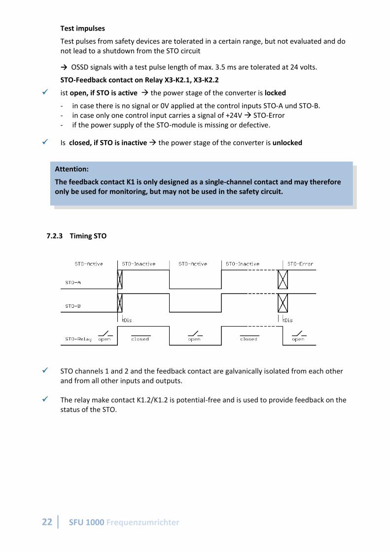
Test impulses
Test pulses from safety devices are tolerated in a certain range, but not evaluated and do not lead to a shutdown from the STO circuit
→ OSSD signals with a test pulse length of max. 3.5 ms are tolerated at 24 volts.
STO-Feedback contact on Relay X3-K2.1, X3-K2.2
✓ ist open, if STO is active → the power stage of the converter is locked
- in case there is no signal or 0V applied at the control inputs STO-A und STO-B. - in case only one control input carries a signal of +24V → STO-Error - if the power supply of the STO-module is missing or defective.
✓ Is closed, if STO is inactive → the power stage of the converter is unlocked
7.2.3 Timing STO
✓ STO channels 1 and 2 and the feedback contact are galvanically isolated from each other and from all other inputs and outputs.
✓ The relay make contact K1.2/K1.2 is potential-free and is used to provide feedback on the status of the STO.
Attention:
The feedback contact K1 is only designed as a single-channel contact and may therefore only be used for monitoring, but may not be used in the safety circuit.

…wenn es um Qualität geht! BMR GmbH
23
8 EMC ✓ Compliance with the EMC limit values is the responsibility of the manufacturer of the machine or
device.
✓ This unit is designed for operation in industrial environments only. When used in residential and commercial areas, additional measures may be required to limit the emitted interference.
✓ The EMC of a machine or appliance is influenced by all connected components (motor, cables, wiring, ...). Under certain conditions, it may be necessary to connect external filters to ensure compliance with EMC standards.
✓ The earth and shield connections that exist within a network between the inverter and peripheral
devices must be as short as possible and with a maximum cross-section. ✓ Control devices (PLC, CNC, IPC, ...) connected to the inverter are to be connected to the common
earth connection bar. ✓ All connections to and from the inverter must be made with shielded cables and the shield must be
earthed at both ends. ✓ Mains, motor and control cables must always be laid separately from each other. If crossings are
unavoidable, they should be laid at a 90° angle. ✓ Lay control and signal lines as far away as possible from the load lines.

24 SFU 1000 Frequenzumrichter
9 Power Supply Basically, the SFU1000 can be operated from one power supply at terminal X1 spindle power supply. The logic voltage for the processor and I/Os is generated internally with the help of a DC-DC converter directly from the spindle power supply. If only the logic section is to be put into operation, the required logic voltage can also be fed in at the separate terminal X2. The inverter is then in operation and can be configured, but spindle operation is not possible. A suitable power supply is available as an option, either as a switching power supply for the spindle supply for 48V or in the extended voltage range also for 72V and also for the 24V auxiliary voltage.

…wenn es um Qualität geht! BMR GmbH
25
10 Dimensions and Mounting
For mounting purpose there are open holes provided for 4mm screws

26 SFU 1000 Frequenzumrichter