Embed Size (px)
Citation preview
National Libfary 1*1 of Canada Bibliothèque nationale du Canada
Acquisitions and Acquisitions el Bibliographie Services services bibliographiques
395 Wellington Street 395. rue Wellington Ottawa ON K I A O N 4 ûüawaON K l A ON4 Canada Canada
The author has granted a non- L'auteur a accordé une licence non exclusive licence dowing the exclusive permettant B la National Library of Canada to Bibliothèque nationale du Canada de reproduce, Ioan, dism%ute or sell reproduire, prêter, distribuer ou copies of this thesis in microform, vendre des copies de cette thèse sous paper or electronic formats. la forme de microfiche/film, de
reproduction sur papier ou sur format électronique.
The author retains ownership of the L'auteur conserve la propriété du copyright in ths thesis. Neither the droit d'auteur qui protège cette thèse. thesis nor substantial extracts fiom it Ni la thèse ni des extraits substantiels may be printed or otherwise de celle-ci ne doivent être imprimés reproduced without the author's ou autrement reproduits sans son permission. autorisation.
Traffic Performances of Assured Forwarding Service in
Differentiated Services
Tingzhou Yang
Graduate Program in Cornputer Science
Submitted in partial fulfillment
of the requirements of the degree of
Master of Science
Frtcul ty of Gnduate S tudies
The University of Western Ontano
London, Ontario
Decernber 1999
@ Tingzhou Yang 2000
ABSTRACT
The differcntiiitcd ser~, içe t DS) approlich. proportxi b> IETF. a l l o ~ s Interner Service
Prwidcrs t ISP) to offer dilfercnt kt,els of services ro aggregiitr rrriffic. One of the hor
rescarch issues is the stud) of the tral'fic behavior in a network ihat suppons Assured
Forulirding I .W) service in DS-capable nettvorls. The thesis prrsenrs ü simularion-blised
peribrmcincr sr udy of AF service under di fferent marking policies and background rraffic
loads. The main objecti~e 1s to evaluate the traffic performance of differenr applications
ce.:. FTP. WWW. Vidro Conference and Ernail) using AF senvice-capable nriworks
undrr diifrrrnt conditions and detemne the effectivenrss of AF service in providing a
better service than today's ksi-effort service. Hrre. the trliffiç performance rneans the
quliliry of service (QOS) different kinds of tr~ffic u n get from the nettvork. c . g rhe
;imount of banduidth FTP traffic can =et rind/or the number of plickets rhat will be
dropped u hen congesrion ocçurs. .More sprçiliçally. ive î i m io evaluate the impact of
angesiion on the Jifferenr rrriffic îloups in an A F scrvicc-ciipliblr network.

ACKNOWLEDGMENTS
I uish io cspress rny most sinsere gratitude and appreciation to m) supervisor, Dr. Abdel
Hakim S. Hafid. for his tirne. suppon. invalucible suggestions and critiçisms.
1 ~iould Iikc ro thlink Dr. Dimitris bllikrlibis. mu co1lr;igue Zhao Chen and al l the
mcnihcrs in ACEC Iab tur thrir suggcscions. encouragement 2nd for the iriendly
c m iroiimcni ihc! providrd.
I uuuld especililly likc to thank rny parents and my brother whose love and
i .nsour ; iyrncnt made it dl possible.
TABLE OF CONTENTS
TAL3LE OF CONTESTS
I.IST OF FIGURES
Chapter 2 Oven+iew of Differentiated Services
2.1 Differi-nt iritsd Services
2.1.1 Dcfinition of Differentiated Services
1.1.1 Difkrcntirited Services Domain
1 Boundary Nodes: Traffic Classification and Conditioning
3.2 .\ssured Forwarding Service
2.3 E.xpsdiied Fonviirding Service
i i
i i i
i v
vii
Chaptcr 3 Jlürking .-Ugorithrns and RIO Algorithm
3.1 Thrce Cdor Marker .Algorithm
3 . Timc Sliding Window A l p n t h m
3.3 Rmdom Early Detecrion t RED) Algorithm
7 4 RED V. irh I I I and OLT (RIO) Algonthm
Chapter 4 Setwork Architectures for Simulütions
4.1 Single DS Domain Set~vork .Arçhitscrure
1 . 2 Mukt t-DS Domriin W w o r k Architecture
Chapter 5 Siniulation Models. Results and .\nalysis 23
5 . 1 CDP irnffic and TCP rriiific (Infinile File Tmnsfcr) in .G S e n icr-Capable
neri! grk 23
' CDP traffic and TCP tralfiç W W W triiffic) in AF Service-Capable nrtwork 33 - . -
3 Irnprovcd-TSW cilgorithm and An Evaluatiori of Marking .Algorithms 38
3.4 Banduidth .illocation in AF Service-Capable Yetwork 46
5 . TCP Round Tnp Timr in AF Service-Capable Network 56
5.6 Support o t E'ipcditsd Forwrding S c r w e ln AF Service-Capable Yetwork 59
5 . Trrir'fic Pcrïormrincs of AF Sert,tcr in Mult 1-DS Domain 66
i . S Surnniiiry 80
Chapter 6 Conclusion and Future Works
6. I Conclusions
6.1 Futurs iC'orks
LIST OF FIGURES
F~yiirc 2.1 .A number o i intcrconnected DS dforn;iins
Figure 2.2 .A nurnbçr of DS houndary nodes and DS intrrior nodrs
Figure 2.3 Logical \.'icu of a Packet Classifier and Traific Conditioner
Figure 3.1 RED Algorithm
Figurs 3.2. RIO Algorithm
Ficure - 4.1 Single DS Domain Nerwork .\rchitçciure
Figure 4.3 Boundxy Ncde of .-\F Scriicr-Capable Yet~vork
F i g i ~ r ~ 4.3 intrrior ';ode of AF Service-Capable Setwork
Figurc 4.4 Multi-DS Domain Setwork .\rchitecture
F i ~ u r t . S . 1 FTP triiffis rsscn ed
Figurc 51 Emriil rraific rrceivrd
Figure 5.2 Hou CIR in TCM ~ t f ~ ç t rrriffic periorrnancs
Figiirc 5.4 tS packrts change to OC1 packers rit klxkcr by serin3 CIR in TCM tu
cfiffercnt vrilucs
Figurc 5 .5 OLT pckcrs ciroppcd in Droppcr
Figurc ;.O [S packers dropped in Droppcr
I-'i_rurc 5.7 HTTP rrciffic reçriwd
Fisure 5 . S Emliil trriilic rece iveci
Figure 5.9 IS ptickcrs change to OLT p a c k s at Mviarkrr bu using TSW and TCM
.Algorithm
Figure 5 . l O Prickets rrrnarked from IN to OüT with different bucket size
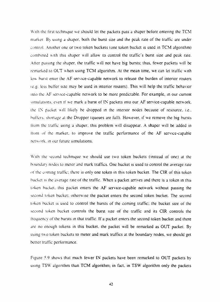
Figure 5.1 1 FTP traffic r e c r k e d with different buçket size
Figurc 5.12 Comparison of three algonthrns lit Marker
Figure 5.13 Throughput for FTP Client 1's traffic
Figurc 5.14 Throughput for FTP Client 2's triiffic
Figure 5 .15 Throughput for FTP Client 3's traffic
Figure 5.16 Throughput for FFP Client 4's traffic
Figure 5.17 Throughput for kst-effort TCP rrriffic
Vlt
F i y r c 5 . I d
Figure 5.f')
Figurc 5.20
Figure 5 2 I
Figurc 5 .22
Flgurc ï . 23
Figui-c 5 -24
Figure 5.75
F i y - s 5.26
F i y r c j 27
"ihruughput fur kst-effon CDP traffic
L'idro Conference Client responsr time
FTP trtlilïs rtxcivsd with EF service triiftic
Erniii t trrift'ic rectliwi with EF trat'fics
Contïguriiiion cit boundary nodes ( 1 )
Conti r u rat ion 31 boundrirp nodes ( 3
Contipurrition boundary nodrs ( 3 i
Conipcirison be t~wcn diffrrrnt rnarking mcchiinisrns at Marker of
Doniriin 3
P a c k s remnrled if the tlirgrt rate 1s 6ORbps
FTP traifis recel\ cd % . h m the tiirgei rate of TS W is 12OKbps and
GO Kbps
P x k c t s rcmrirked tf TCM riloorithm is uscd
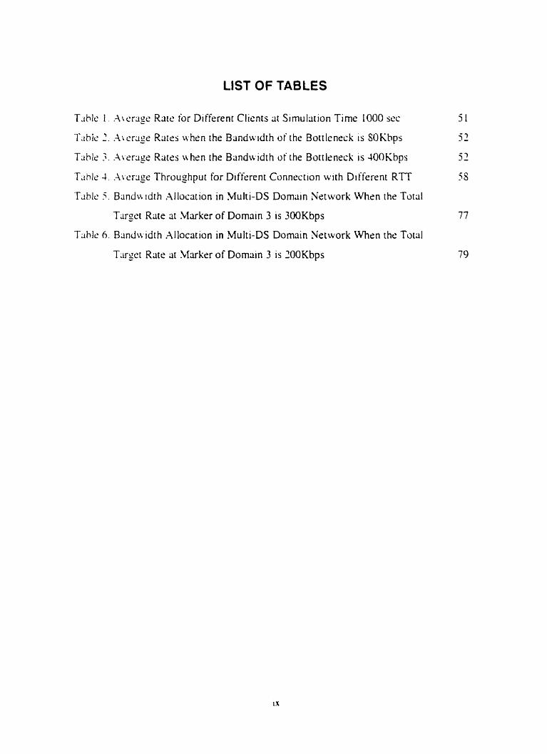
LIST OF TABLES
T ~ h l c 1 .Ar erage Rare for Different Clients at Simulation Time 1000 WC 5 1
T d h k 2 . .-\it.rrigs Rates when the Bandwidth of the Boitlenrck is SOKhps 52
Tiihlr 3 . .-\vrr<ige Rates i ihen the Bandwidth of the Bottlrnrck is 400Kbps 52
Tahlc. 1. .-\ic.rrigc Throughput for Diffrrent Conneçtion with Differcnr RTT 5s
Tiihlt. 5 . Band\\ tdth Allocation in Multi-DS Domain Network Whsn the Total
Targer Rate at Marker of Dornain 3 is 300Kbps 77
T;hk 6. Blindtvidth Allocation in ,Multi-DS Domain Network When the Toial
T;ugr.t Rate at Marker of Domain 3 is 2OOKbps 79
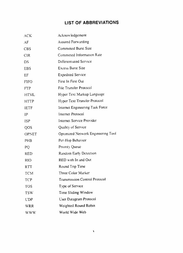
LIST OF ABBREVIATIONS
.AC K
A F
CBS
CIR
DS
EBS
EF
FI FO
F f P
H ' N L
i-f TT P
IETF
IP
ISP
QOS
OPSET
PHB
PQ
RED
RIO
RTT
TC >I
TCP
TOS
TS Li '
C-DP
Li'R R
Li ' LV IV
Xssursd Fonvrirding
Commirted Burst Size
Cumrmtted tnformrition Rate
Differcnt ilrted Service
EXCCSS Burst Size
Expeditrd Service
First tn First Out
Fi is Trans fer Protocol
Hyper Tsxr bhrkup Langulige
h ~ c r Text Transier Protocoi
Internet Engineering Trisk Force
Internet Protocol
[nternet Service Provider
Qualit! of Service
Optimized Network Engineering Tool
Per- Hop Behriuor
Priorit > Queue
Rrindom Early Dctsçtion
RED luth In and Out
Round Tnp Time
Three Coior Marker
Transmission Control Prorocol
Type of Service
Time Sliding Window
User Dar agram Protocol
Weighted Round Robin
World Wide Web
Chapter 1 Introduction
This i h s p t c r hgins u ith a prescnr;itic>n o i rhc niuti\aiions ~i this :hesis uork. Then. i t
dcsirihcs thc ohjcstiws rhltr arc simed b~ ihis thesia w r k . Findly. thc orgsnization of
the rhcsis document 1s prcsrnted.
1.1 Motivation
Thc Internet 15 iurrcntl>. based on the bat-effort mode1 ;incf trtirits riIl the rrriifics in the
.;;imc \r 2 ) . Thc k s i - e i t r t mode1 haa k e n juccessiul r i I l notr kcausr a large propanion
oi the irsific in rhr [ntcrnci is TCP-bascd. Thc TCP cnd-to-end congestion conrrol
rricc hiinisriis i c 111 force the TCP sources to h i k ot'f u henewr scingestion il; Jc tmsd in
rhs n t 1 . Houcwr. such ti dependencc on thc cnd s)stems' cwperation is
kcorninp incrtxsingly unrealistic. Givrn rhe iurrent &sr-ct%n modd w t h FiFO
qucuiry inside ihc nct\rork (Le. routefi). it 15 rclltrivrly easy for non-adaptivt. sources to
gain grc;iter shi1rc.s of nrrwork b;ind\~idrh mi rhcreb! stiirvc other. wIl-bchaved. TCP
wurccj [I 1. For ex;impie. a srcrdy CDP juurcc ma). sinipl? continue to scnd at the same
r;Itc ivhcn LKSJ w t h congestion uhile other TCP sources back off The hst-cifon rnodel
is d s o inadquate for applicxions. wch as rcal tirne audio and vidco. uhlch rcquire
ri.;plicic hmdu idth and dclay guur;intc.es. Sloreover. rhc k t - r ffon rnodçl treats 311
pxkeis cquiilli once theu hiive hccn injrcted inio rhc netwrk. Thus. it 1s dil'ficult for
Intsrnrr Scrute Pru~.tdtlrs iISPs) tu prowic scrutes thtit rire cornmsnsurritc: with the
eïpccrli[tiinj u i consumers uho are uilling to pci) morc for s h t t c r cisss of service.
The cthoic isjücs h u e Icd to (i number of pn)posals for providine diffrrrntiliicd services
[3 ] in thri Interner. Thc ciifferentintrd service ~ipprotich illows service providers to offer
d:ffcrcnt levels of services CO a few classes of aggrcgated traffic flows in a differentinted
jcr\lse cloman. For sxiimple. an ISP ma! ufkr t i r a levels a i services - a prcmurn
jcr\.lcC [-!] h r customers &ho rire willing to pay mure anci ri best-effort service rit 3 lower
price. B ) using this w y . traffics likr vidro and audio u n gtt better services. such as low
dclay and high band\vidth. Currently. two t-pcs of services have bern proposed in the
W t h ihc irirrcrciucrion or' .AF servicc and EF srri i c r . a number of qussiions/issurs ;irise.
Thr.5~ q ~ ~ c ' ~ r i ~ i n s / ~ s s u s include: ( 1 ) Ho\\ dws CDP irciifiç affect TCP trliffic in AF
5c.t-r iic-c;ip;ihlc net~wrk: i 2 ) Ho\\ k t t r r the service. provided to customrrs. is in AF
sert i ~ ~ - i ; i p i i h l ~ ncitr orks; ( 3 ) Hokit docs the bandwdth allocation for difkrcnt customers
in .-\F wucc-i;ipiiblti nrtwxks; ( 4 ) Hoiv the impacts of round tnp timc tRTT) in AF
w r ~ i c r . - ~ ~ i p ; i b l ~ nciuorks: ( 5 ) 1s it possible ro jüppon the applications ~r ith lou d e h y and
Iou jiiit'r in AF jcnise-capable net~vorks: ( 6 ) How the performances of ~pplications in
mu Ir I-DS &)main .AF service-slipable networks.
Objectives
Iii;itioni W.$. FTP. W V W . Vidru Cmicrencs and Emÿii) usin3 .AF service-capable
.rorh iiriclcr diikrcni iunditions. Huc. the traffic performance melins the qudity of
w r \ iic c (?OS i (S 1 ciifferrint kinds ut' triiiiii icin get from the Inremet S m - i c e Provider
I ISP), such A.; thc <imounr of bandwirlth 3 FTP rriiffic c m sri from ISP: rhc number of
p i i i h ~ t , itiai u i l 1 lx droppsd when there is congestion in the bottleneck l ink More
spcc i i i id l~- . wr. aini to r~alurite the impact of congestion on the different traffic flows. By
iin;il>zing thc triiffic performance under difkrent conditions. we should be able to
dctcrniin~ the bchiivtor of applications in .iF srrvice-capable netu-ork and thcn provide
;insv.c.rs to the issues proposed above.
In !hi5 t h ~ ~ i j nork. ii nurnber of simulati«ns have k e n performed to svduate A F service
on a iinglc. d o m m network and on a multi-domain network. A11 the sirnul~rions have
kc:n pcriormed uj ing 0Pi;ET 5.1 [9]. a ncrwork simulation tool developed by Mi13.

1.3 Thesis Organization
Thc rcsi oi' rhc t h c ~ i j 1s organizctd 2s folloiis. Chiiptrr 2 prescrits the concepts of
di I icriini i l t r cd sen tcç. .Assureci Forwrdinp s e n ics mi Expeditrd For'oru a rd in Service.
Ch.ipier 3 inrroduccs the basic ideas of TCM. TSW and RIO algonthms that have been
uicd W r ihc simulations. Chapter 4 presents the ncrwork architectures ussd for the
.;irnul;itiiins: both sinsls-domriin nctuork and rnulti-domriin nctwork rirchitectures are
pro\ ided. Chaptrr 5 desçnbes the drtails of the simulations that have bern prrforrned:
jimul~ition results 2nd their analysis are also presentcd. Chapter 6 concludes the thesis
.inci p r a ides directions for future reserirch.
Chapter 2 Overview of Differentiated Services
This chiipter prcscnts ;in o w r u r u oi the ionccpts of Diikrentiated Services. Assured
Foru miin2 .;ervicr. and E.~pcditsd Foruxding service. These concepts are the basis of
rhc siniul;itions thrit u.111 ht. presentsd in the iulIowin_o shaptcrs.
2.1 Differentiated Services
3.1.1 Definition of Differentiated Service
Thc di iicrcnt i m d seri iccs i DS 1 [ ? ] circhitrcturc. is basrd on a simple mode 1 n here traffic
cnttmns LI nctuorh is sliissified and possibly condmoncd at the boundarirs of the
nct u ork. ;ind x s i y e d ro diffcrcnr hehavior aggreptes. Each behavior aggrcgate is
idcnriticd h' ;i singlr' DS codepoint 1101. Within the corc of the netwrk. packets are
i;)rv.ardcd ~ccording ti, the per-hop behuior t P H B ) [3] associtited with the DS
codepoint. The ultimcite god of the differcntirircci srr\ iîes is io provicie nrtwork suppon
for proiiding rnd user s e r u x le~els. Thr per-hop hshrivior is the entcmlilly observable
iUr\urcling hthlitior cipplied at a DS-cornpliant no& to a DS behwor aggregatc. %y
j upp - t t ng d~il*crcntimd scrtxe in Internet. rhe netuork jervice prouciers could offer
J i ik rcn t 1) pt.5 or p d e s of 5ervicr.s to diifcrent customsrs ( c g . \ ideo and audio require
lou dcI+ ~i hile filc rransmission require high throughput). This melins thiit the çustorners
\r ho w n i to pli! more could get berter trafic performance from the neti~orks.
I n order to provide diiferent classes of services to different customrs. the TOS (Type of
Scrviçr) field ln the hcilders of Ipv4 packets may be used [loi. Different values in this
field indicrire different tkpes of services the cusrorner rnay get. A value in this field is also
criI lcd 3 DS codepoint. The TOS fields of the pacliets could be set by the traffic sources
or could rilso bc set rtt the boundary nodes of every DS domriin the packets enter.
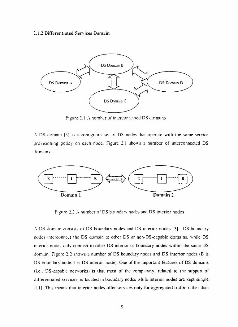
.-\ DS duniiiin [31 is a contiguous ser of DS nodss that operate with the same service
prousionin2 polisy o n cach node. Figure 2.1 show a number of interconnccrrd DS
Figure 2 . 2 A number of DS boundary nodes and DS intrrior nodes
h DS domain consists or DS boundary nodcs and DS interior nodes [3]. DS boundliry
n d c s intcrconnecr the DS domain to other DS or non-DS-capable domains, while DS
intrrior nodrs only connect to othrr DS interior or boundary nodes within the same DS
domiiin. Figure 2.2 shows 3 numkr of DS boundary nodes and DS interior nodes (B is
DS buundiiry node: 1 is DS interior node). One of the important features of DS dornains
i . DS-capable nrtworks) is that most of the complexity. reiated to the suppon of
di ffercnt iiirsd services. is locsted in boundxy nodes while interior nodes are kept simple
[ 1 I I . This mcons chat interior nodes offer services only for aggegated traffic rather than
on 3 pcr-tlou biisis. I t is the boundary nodes' responsibility to classtfy the packsts into
wsr;il t x h w i i ~ r aggrrgates. meter the mit ic Iisainsr profiles. mlirWremrirk pcickets.
shiipc or &op thc packers. etc [El. (a description of these operations is pressntrd in the
nclt jcition,. Intcrior nodes will just t'orivrird the riggregrited rraffic riccoi-ding to the
iocicpoints (SC[ h> houndary nodss or tlow jources) in the packers' heridrrs.
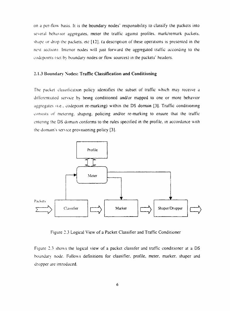
2.1.3 Uouiidary Sudes: Trafic Classification and Conditioning
The prichct sl~ssit'iclition policy identifies the subsrt of traffiç uhich ma) rcceivc a
diiicrcnri:irr.d scrvics b) king conditioned and/or mapped to one or more behavior
Jggrcgiircs i M . . mirpoint re-muking) within the DS domain [3]. Traffic conditioning
ionsisr.; ot' nicicring. jhsping. policing and/or rr-mÿrking to cnsure that the traffic
cnrcring rhc DS dumain soniorms to the rules speciiird in the profile. in accordlince iv i rh
rhc durnain's scrk ics provisionmg policy [3].
Figure 2.3 Logical View of a Piicket Classifier and Tnffic Condit ioner
Figure 223 ~ O N S rhr logical view of a pücket classifer and traffic conditioner at a DS
boundary n d e . Follo~rs definitions for classifier. profile. meter. marker. shaper and
Jrvppsr rire introciuced.
In a boundary node of a DS domain. n flow of pltckrts wtll bc classifird tnto sevcral
slasses hy ;i slassiiier [31 [ E j . The classifier wiII clrissify thc rraiiic by rtxding ihe
codcpoint in the packet's hclider i f this packet hris already k e n pre-rncirkcd: other\~ise. it
\uII r e d othcr tields in the pÿckct's hradrr. siich as sourcddesiinarion IP ddress and
pi-i>tc>iol identifier. For rxsmple. i f we want to proteçt the TCP traific from L D P traffic.
\\ci jh{>ulcl mark the TCP traftk with loti. drop precedcncr and mark the UDP rrriffic w t h
high &op prccrdence nt the boundary nodes. To idenrify whsther a packrt is UDP packet
or TCP packet. the classifiers read the Protocol field in the IP paçkct's hciidrr. Thus.
~it1c.n congestion occurs in thc nerwork. CmP packets wll he drupped first bu interior
nodcr;. The metsr [3] [12] at the boundary nodes rcill thzn merisure the traffic stretim
agiiimi 2 triiific profile [3] [12]. uhich specifirs the temporal propsnies of this siream
.;clcsicd h! 3 s1;issifit.r. .A profile bascd on 3 tuken buckt ma) I w k Iikc '*codepoint = .Y.
u i z rukcn buckct R. B". This profile rnerins that al1 the pacbets w t h codepoint S wll bs
mtxsured ~igctinst a tokrn buckei metcr w h rate R and burst size B. Out o i profile
pxkcts arc' thosc plickets that amve when insutficient ioksns arc a~.riilribls rn thc hucket.
Tticsc uu i c i i pratilc plickets may tx remarked with a l u w r priant? b) a rnctrkcr. shripcd
h! :i ih;ipcr or dropprd by a droppcr ;it the boundltry nodes. Packet markers [ ? ] [131 ~ i l l
sct thc DS tield of a packrt to a paniculiir codepoint. adding the rnrirked piickst w ;i
piirtiiuilir DS bchavior ti_osregiitr. Shüpers [3] will dsliiy somr or l i l i o t the packets in a
trai'tïs strc'm in ordcr to brtng the stream into cornpliance with ;i trciffic profiIr.. Droppcrs
[il W H JISL;LT~ S O ~ C or 311 of the pdckets in a triiffic srrccim in order io bnng the jtrccirn
in io cumpliiince w t h ci traftic protile. This proccss is rilso knoun as "poli~ing" thc
st rc;Lm.
Thcrc Iirs tau kinds of differsntiatcd services that have bsrn proposeci by IETF: ( 1 )
Assucd Fonwding (AF) service; and (2 ) Expeditcd Fowarding (EF) seruce. A detailrd
description of these rwo services 1s presented in the follwing sections.
2.2 Assured Forwarding Service
Assursci Fur\i.rirdin_o ( A i 3 service [il is 3 serucc th31 a11oivs the 1ntrrnt.t Sr'rvice Provider
( ISP) ri> o i k r different Ic.~,cls of iorwarding assurances for I P plickets reçeived from a
custonrr. In this ihcsis. ive wiII mainly iinalyze the triiific performrincr o i diikrent
appliccitions in .* s c r ~ ~ c e netuork. The ides behind AF 1s to give the customer the
assurance of a minimum throughput. s w n during pcriods of consesiion. while ~illowing
him/hcr io consumé more bandwdth whcn the netuork lorid is low. Thus. ri connecrion
using the AF service should achirve ii throughput equiil to the subscribed minimum rate.
d so slillsd tlirget raie. plus some shiue of the remliining bandwidth g incd by competing
ir ith dl the ricti~c. b w - d o n connections. In a typiciil ;ippliciitian. (i cornpany uses the
Internct to intcrconncct its geogr3phiç311y distributeci siicr and ucints an assurancc that fP
priçkrtts within this "Intranrt" are loruxdrid with high probability as lang as the
aggregate traffic tiom s x h site does not c'xccc'd the suhscribed information rate in the
profile [7 ] . I t is Jesirable that a site ma) excced the subscribed profile uirh the
iinderstmding th31 the cxcr.ss ~rriffic is not dc ln~rc l l u i t h thc same probiibility 2s the
r r d t i c thrit is u i t h in the profils.
Four .\F C I L I S S C S arc Jefinrd in ihc AF service [7] . In t . xh :\F slliss. IP packrts crin be
iricirkcd w t h onc of threc possible cirop prcccJt.nics. In u s e of congestron. the drop
preccdence of n pacher detcrmines the relatiw imponiinsr c>i the packet within the .AF
slass. A cimgcstsd DS node tnes to protect piickets w t h l o w r drop preccdence (rom
k i n g Iost hy distxding pxkrts tuth highrr drop precrdence. By using the drop
prcwdence. we crin eifectivrly control non-sdiiptive wurces k g . UDP sources) from
:citins more thlin thelr Fur share of nrtwork resources. In the AF service network mode1
uti used in rhe simulations (thac wiil be presentrd in the following chapters). there is only
une h F s liiss thar hlis t NO drop precedences. in profile ( IN) and out of profile (OUT). The
mufiution behind this choice is to have ri simple rnodel. for AF service. that is easy to
implcmrnt. Furthermorr. tt h3s k e n reponcd in [ l 3 ] that using threc drop precedences or
nro h o p precedrncrs in an .-\F service class hiis rtlmosr no impact on the performance of
the s)stem.
l n ihis thc.;ii uork. J rnarkinp algorithm iThrer. Color Marker [IJ] or Time Sliding
\Vitidou [ L 5 ] ) .tnd RIO (RED with IS and OLT [13 ] [ i b ] ) algorithm have k e n used to
i n i p l c n i m the .\F s s r l i ~ s . Description of t h w cilporithrns is presented in Chapter 3. The
mrirhing ;ilgurithms tTCM or TSW) hciw k e n implcmcnted î t the boundary nodes of an
F service-cap netu ork to mark rhe packsts wth different drop precedences and RIO
~ l y m t h i n has k e n implrmentsd in the tntrrior nodes of an AF seruce-capable network
io rn;iniigr p;iihsis diiicrently açcording to the packet's drop precedence.
2.3 Expedited Forwarding Service
E\pc.Jiwl Fiir~w-dins t EFi service [6] proudcs lou loss. loti. larensy. low jittrr. and
h u h d r h parantccs on end-to-end bms though DS domliin. Examples of applications
h i might usc rhis jcrviie ÿrs vidro and ;iudio bassd ;ipplicmms sinçc they rcquire low
ji[tcr ;mi I O I L Jc Iq to bc. of licc~ptiible qual~ty.
Luss. I ; i t ~ n i > 2nd jitrcr arc 311 due to the queues traffic traverses whilr transiting the
nctv.~orl. Thcrcforc prouding lou loss. Iÿtr.ncy and jirtcr for somc traffic aggregiite
n icms cnsiiring ths i the triiffic sees no ior ver? jmall) queues; this can be lichirved by
cniuring t h x 31 311). ime. the output cspacity is highcr or equcil to the input ccipactty of a
giwn LIUCLIC 16). Sewrd types of queue schrdulin_o rnechiinisrns rnay be employed to
irnpleriicni thc EF st.ru~.c [6]; rumples are priority quru~no (PQ) model and weishted
round rohin i WRR 1.
In this rhcsis ~vork. L w used the pnority queuing model to support EF service. Lising this
mudel rcquircs thc integrrition of some melins to limit the damase EF traffic could inflict
on othcr trriific. such ris AF or k t - e f fo r t tr~ffic. .A token bucket or a rate estinutor must
te impicrncntsd at the boundary nodes in a uay such that traffic that sxceeds this limit
rnust be discrtrdsd. By domg so. delay is not introduced to the traffic.

Chapter 3 Marking Algorithms and RIO Algorithm
In t h 1 5 i h a p i ~ r ire prcsciit an o w r u m of rhc markmg dgoriihms (Three Color Marker
.tlgosiilirn met Timc Sliding \Vindow algorithrn) uscd b > the bundary nodes. oi an AF
icrl,iir: clom;iin. in our simulations that wil! be dessribrd in the lolloiving chaptrrs. We
ii I I I ~ i s u prcacni an uwrviar of RED and RIO (RED wiih IS and OLT) alporithms used
h) ihc inicrior nudcs. of an .-IF service domain. in our simultitions.
3.1 Three Color Marker Algorithm
Thc T h r w Color Mlirksr (TCAI) [HI cilgorithm is a kind of token bucket (171 algorithm.
I r nictcrs m I P plickst stresm and marks its pxkets rither ge rn . yellow. or rcd. Muking
r i h j t l c i on ri Cornmlttt'd Information Rrite (CIR) and tuu rissocirired burst sizes, ri
~'~ininiirtcd Bunt S I X iCBSi anci Iin E..riess Burst Size (EBS) (141. CIR 1s mesurcd in
h w , pcr . ~ i i > n J r;>r IP pÿch~ts. The CBS and EBS are mccisured in b'es. A packet wil l
hc. riiiirkcd ds g r c w II' i t doesn't rncred the CBS, )ellow i f it does exçcsd the CBS. but
not thc EUS, 2nd rcd othsrwse.
7'hc Mctc.: mctcrs i.;iih piickei 2nd passes the pticker and the rneicnno resuli to ihe
h1xkr.r ~ i i shoii n in Figure 2.3: in our simulaiions. the Merrr opercites in Color-Awre
m d c [ 141; this mecins [bat the Meter assumes thât the packets have been pre-marked.
1-licn. thc 'rlxkcr remiirks. i f necrswry. the paçkrt aciccording to the results of the Meter.
Ttic htctcr nicrisures the piickrt Stream by using two token buckeis. C and E. that both
shtirc. rhc cornmon rare CIR. The maximum size of the token bucket C is CBS and the
niaxirriuni s i x o i the token buckrt E is EBS. The token bucket C and E are initially (at
ttnic 0 ) fult. 1.e.. the token count TCiO) = CBS and the token count TE(0) = EBS.
Tticreriiicr. the token counts. TC and TE. are updated CIR tirnes per second as follows:
IiTC c CBS
TC = T C 4;
Elsr. i f TE < EBS
T E = T E + I ;
El sr.
Scithcr TC nor TE uill be increméntcd;
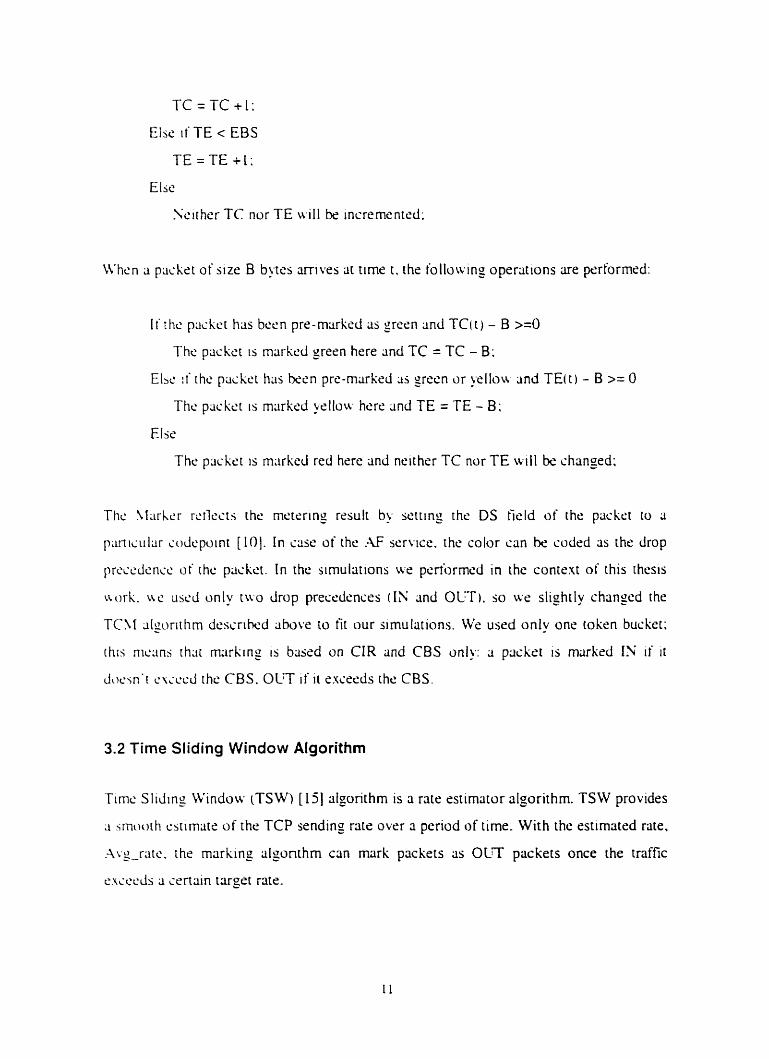
\ twhsn (i piickst of size B bgtcs arrives ac timr t. the iollowiny operations lire performrd:
Ii r hc p d x t has bcen pre-markcd as green 2nd TC( r ) - B >=O
The pac kct is miirked green here ;ind TC = TC - B:
Elbe :i' thc packet has becn pre-miirkrrl as green or ycllou and TE( t 1 - B >= O
The pxket is markeci yellou- hert. 2nd TE = TE - B;
Else
The packet is mnrkscl red hrre and neither TC nor TE will be changed:
Thc \ f ; i r k r rcrlwts the metering rssult by settrng the DS field of the piickct to ri
p;~r"iultir cdcpoint [ I O ) . In u s e of the .\F service. the color can be codrd as rhe drop
prcscdc.nse o f rhc pircket. I n the sirnuliitions u.s pcriormd in the content of this thesis
iriirk. LW uscd only tuo drap preçcdences (IS and OLT). so uer slighrly chmged the
TCM dgorirhrn dcssrihed above io f i r our simuliitions. WC usrd only one tokrn buçket:
h i . ; nictins th;it mtirkinp is biissd on CIR and CBS oniy: a packet 1s mÿrkrd IN i f i r
docsn'r c\;cècl the CBS. OUT if i t sxcssds the CBS.
3.2 Tirne Sliding Window Algorithm
Tirne SIiJing Window [TSW [[Ij] algorithm is a rate estimator algorithm. TSW provides
a srnrwth cstimatc of the TCP sending rate ovrr 3. period of tirne. With the estimated rate.
.-b--r:ite. the marking sloonthm can mark pxkets as OLT packets once the traffic
e ~ c c c i s ;l certain trtrget rate.
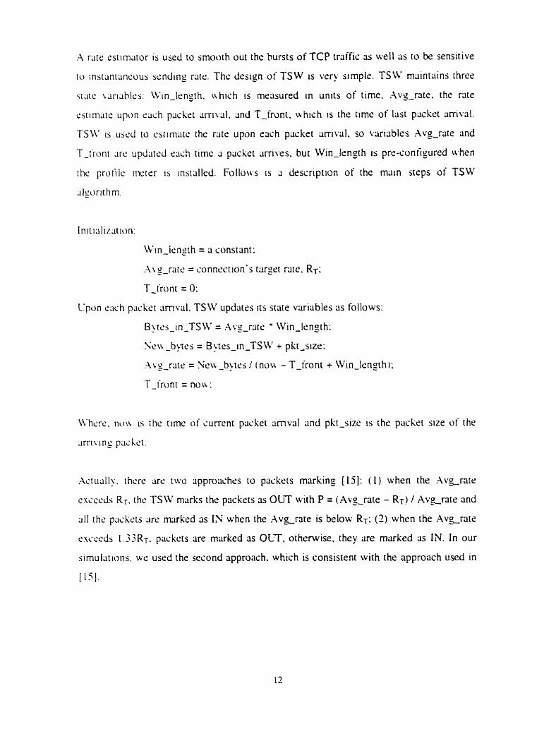
.A r m cstirnritor is uscd to srnooth out the bursts of TCP trriffic as well as to be sensitive
tu insrmiancous scnding raie. The Jeslgn of TSW is ver? simple. TSW m;iintains thres
w t ç u - i d h : \Vin-length. ir hich is rnecisured in units of time. Avg-rate. the raie
cstimJtc upon w c h pscke~ ;irrn;il. and T-front. ~ b h i c h is the time of last packrt m i v a l .
TSW i j U S ~ io est ini;ite the rirtr upon e x h packet iirrival. so varicibles Av_o-raie and
T-ironi .irc upda td ~ i i i h rime 3 packet arrives. but Win-length is pre-sonfigured when
the protilc mctsr i j instdled. Follows is ;i description of the main iWps of TSW
&urit hm.
.-!ctii;iII~. ihcre arc rwo iipproachrs to packets mxking [ I j ] : ( 1 ) when the A v ~ r a t e
essceds RT. the TSW marks the packets as OUT with P = (Aq-rate - RT) / Avgrate and
a11 the prisliets are m r k r d ris IX whrn the A v ~ r a t e is below Rr: (2) when the A v ~ r a t ç
excccds l.33RT. packets rire marked as OLT, othrnvise. they are rnarked as IN. In our
sirnulsti«ns. ire used the second approach. which is consistent with the approach used in
[13 ] .
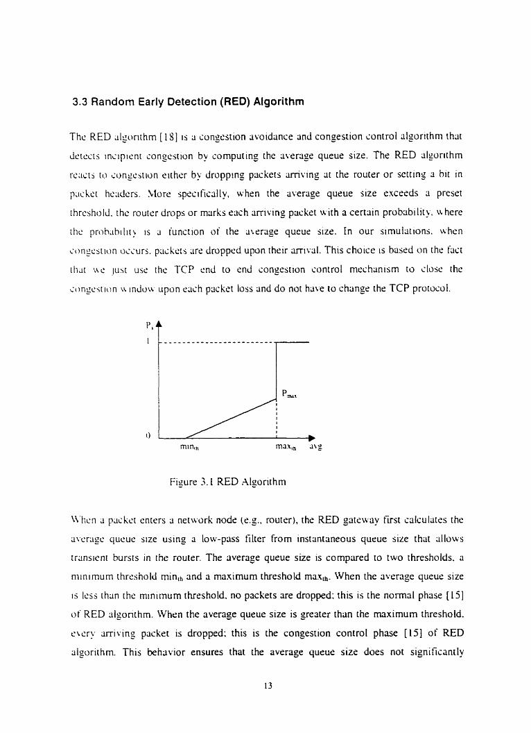
3.3 Random Early Detection (RED) Algorithm
The RED dgorirhrn [ l Y ] 1s a congestion woidançe and congestion sontrol algorithm that
detest j incipient congestion by comput mg the avera35 queue sizr. The RED algorithm
rc;ictj to xmgcstion cithcr by dropping packets amving at the router or setting a bit i n
pxhct hccidcrs. htorr sprcifically. uhsn the average queue s u e excrsds a prcset
[hreshold. the router drops or marks sach cirriving pciçkrt with a certain probability. u herr
i r i 1s a function of the atrragr queue s i x . In our simulations. whcn
cori~csiim occurs. pcttkcrs iirs droppcd upon their mival. This choice is btiscd on the fiicr
r l u r uc ju\ t usc ihe TCP end to end congestion control rnechanism to close the
c o n p i ion ii indon upon crich packrt loss and do not have ro change the TCP protocol.
Figure 3. l RED Alporithm
W e n 3 piickct enters 3 network node ( c g . router). the RED gateway first slilculatrs the
cticragc qucue size usin_o a low-pnss filter from instantaneous queue size that allows
transisni bursts in the router. The nverase queue size is compared to two threshoids. a
niinimum thrrlshold minth and a maximum threshold max,h. When the average queue size
is less than the minimum thrrshold. no packets are dropped: this is the normal phase [ l j ]
of RED aiponthm. Whcn the average queue size is greater than the maximum threshold.
ewry arriving packet is dropped: this is the congestion control phase (151 of RED
algorithm. This behiivior ensures that the average queue size does not signifiianrly
C'WCL'J ~ h e mmmum threshold. When the average queue s i x is b s twcn the minimum
mi rhc ni.i\imum threshold. raçh arriving packer is droppcd wth probobiliry P,. u hcre
P, 15 A riincrion of the average queue size avg: this 1s thc congestion a~oidvnie phiise [ l j ]
o i RED dgonilim. Etich packet drup serves the purpose of indirecrl> n o t i t y g rhe
Q rate. isourcs) end host's transport layrr to rrduce its scndin,
.A RED algcirirhm is configured with the followng plirameters: min,,. 2nd P,,,. I t
uorks as illustratrd in Figure 3.1: the .u axis indiciires the average quruc size. WC. - that is
c~lcul;itr.d b~ using (i low-pass filter of instantanmus queue size upon eltch packrt arriva!.
The sus indicrites the probability of dropping an miving packei P,. The threr phases of
RED ;il~orrthrn are s h o w in Figure 3.1.
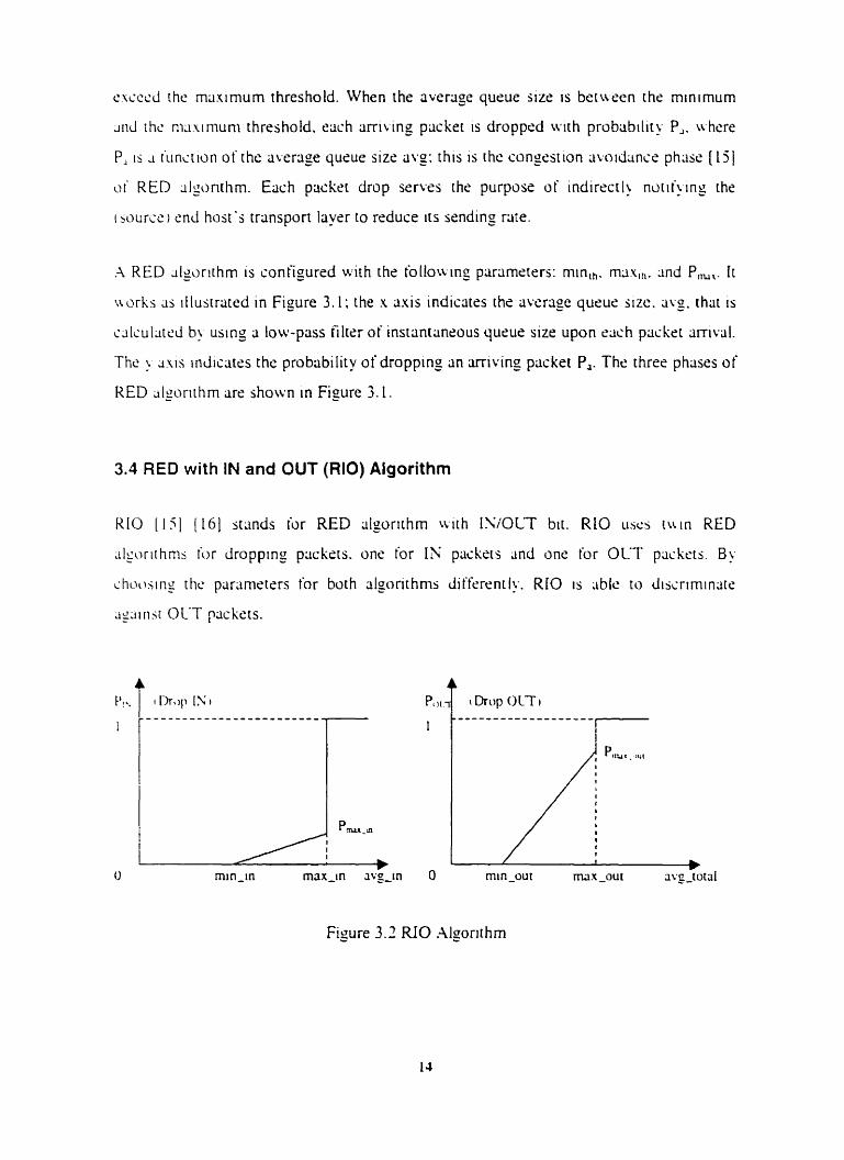
3.4 RED with IN and OUT (RIO) Algorithm
RIO [ l i ] (161 stands for RED cilgorithm u i t h ISi0L-T bit. RIO uses ruin RED
.iIgoriihnis for Jropping ptickcrs. one for 1s ppuskeis anci one for OUT packets. By
ihao.;inr t hc parameters t'or both rilgonthrns dilfsrenr ly. RIO is able to dissrimin~t<:
c i y r i s t OLT packets.
Poc-
O min-in max-in avg-tn O
Figure 3.3 RlO Algorithm
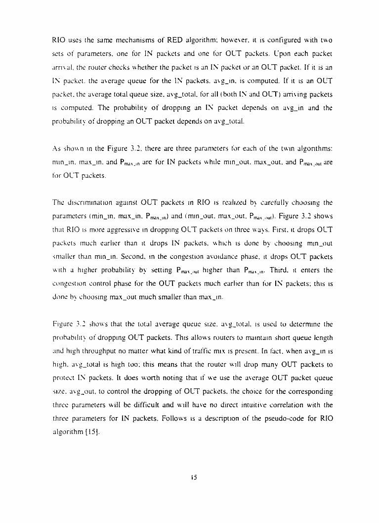
RIO uses the urne rneçhrinisms of RED rilporirhm; howe~,er. it is confipred with tuo
sets of parametcis. onc for IN pückc'ts and une for OLT packets. Cpon r x h packet
.irriuI. the router checks whrthrr the p d z t ts an 1s packci or Lin OLT packsr. I f i t is an
IS packct. the rtw-agc qucue for the IX pcickets. ALE-in. is computed. If i t is an OLT
paikct. rhc average rotal qurue size. avz-total. for rill (both 1': 2nd OLT) a i~ i r ing packets
is sompured. The prohability of dropping an IN packet dcpends on iivg-in and the
pi-obability of dropping an OLT packer drprnds on rivg-toial.
.As shou n i n the Figure 3.1. thsre are three piirrinicters h r e x h of the t w n dgonthms:
niin-in. rn3.c-in. and Pm,-,, are for IN packcti whi l s min-oui. mux-out. and Pm, ,,,, are
for OLT pxksrs.
Thc disiriminittion qtiinsi OUT paçkts in RIO is rr.alirc.d b! cmiul ly choasin~ the
prirsmctsrs (min-in. rnitx-in. P ,,-,,) and (min-out. ma-out. P ,,-,, .,). F!gure 3.2 shows
th;it RIO 15 more cisgrcssivc in dropping OLT pri~ketj on thrce u q s . First. it drops OLT
piichctb inush carlier thrin i t drops IN prickcts. u h i sh is dune by choosing min-wr
jniiillcr thlin min-in. Srçond. in the congestion rivoidrincs phase. i r drops OLT pxkrts
urith L( higher problibility by serting Pm,-.,,, higher than Pm,-,,. Third. it m e r s the
songcst ion control phase for the OUT packers muçh carlier than for IN pcickets: this is
Jonc h> chuosmg man-out much srnallsr than miin-in.
Figure 3.2 jhutr,~ ihrit the totiil riverlige queue size. a\s-t~tril. IS usrd to clctcrminr. the
proh;ibilit! of dropping OUT packers. This iillo\i.s routers to maintriin shon queuc lengrh
m d high throuiJ-tput no mritter what kind of traific mi. 1s prcsent. in inci. whrn avs-tn is
high. wg-total is high too; rhis means that the router uill drop man? OUT packets to
protect IS pcickets. I t dors wonh noting that i f we use the auxlige OLT packet qurue
WC. civg-out. to control the droppine of OLT packets. the choise for the corresponding
rhrw pmmctrrs will br difficult and wil! have no direct in?uitics correlation with the
thrw parameters for IN pcickets. Follows is a drssnption of the pseudo-code for RIO
r i lpi thm [ l j ] .
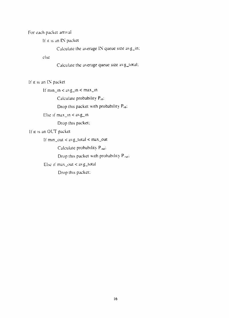
l i l t IS ;in [ Y packet
I t min-in < aw-in < m u - i n
C3lsuliIte probabilit y P,.:
Drop ihis packet wth probability P,,;
Else ~i ma.\-in c a v g ~ n
Drop rhis packet:
[ f i t 15 an O L T ppctcker
I f min-oui < liw-tutal c max-out
Calculate probtibi lit>- P.,,:
Drup this pcicket ~ i t h prohabt l i t y P..,,:
Elsc i t ' mas-out c ;iv~-totlil
Drop this packet:
Chapter 4 Network Architectures for Simulations
I n i b ch~ ip t s r . ~c prescnt the networb architectures L w used for our simulations to
~ i i d > ~ c . ihc traffic pcrlormrince of AF service. First we present the sinjic DS domain
nci\r~i-L .irchliecture. Then. u e present the multi-DS domain network architecture that
h:is hccn uscd ior rvîluating the AF service on (i multi-DS domtiin network. We also
d c s i r i b ~ thc. bchauor of the boundary nodes and interior nodes. of the A F service
ne[\\ CI^-l. p s o c ~ ~ n ~ thc packers 2ener;ited b! cipplicritions/services undcr simultitions.
4.1 Single DS Domain Network Architecture
\YS d ~ i l J ~ . d . t h t . to pcrforrn sirnularions on 3 singlc DS domain netuork archiiccture to
;in.il\/c. rlic ti-;iiiic. periormlincr. in an AF srrvic.s-capable network. This w u rnorivatrd by
the i'.iir t h t w-1~ DS domiiin nstuork architcsture is simple and rslativcly easy to
oh~cr~c , . i i i . i l~rc . thc rrsuitj. The singie DS domain nr.tu.ork architecture is s h o w in
F iy rc 4 1 .
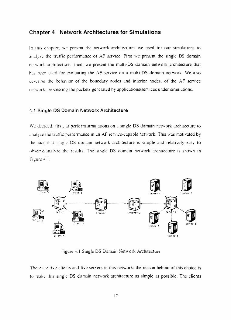
Fiyiirr 4.1 Single DS Domain Serwork Architecture
Thcrr. drc i i ~ c clients anci five servers in this nrtwork: the reason behind of rhis choicr is
to niiihe rhis single DS domriin network architecture 3s simple lis possible. The clients
.ilid serwrs tire FTP. Emiiil. H T P or Vidco Conference clisnrs and servers açcordin~ to
di ikrcnt simul~tions. llsrker and Marker 2 are thc boundnry nodes of this h F sen ice-
i . iplibl~ ncruorl and Dropper and Dropper 2 are the tira interior nodes of this h F
hcrt ics-cipliblc nctuork. The link k t w r n the Dropprr 2nd Dropper 2 is the bottleneck
Iinh of' this nctworl. Wt: ni;iinly ;innl>zs i h r traific performance of this hF seruce-
c.ip.iblc. nrii\wrl, uhen thtire 1s congrstim in this bottlenrck Iink. Traffics art: sent t'rom
('l~cnts ILI Sc'rwrs in niosi o i our sirnuiarions. The cucrption is the simulation rhat
inwlws ii'WW traffic. whrre clients scnd reqursts tu the srrvers and the servcrs send
W h pages b x k to the clients.
In ail of ihc simulations. triiffic sources pre-mark the packcts they generate; ar the
n r nodcs of the .\F service-capable nctwork csre Figure 4.1 ). t h e markrr ma'
rernuk wme o i thcse p x k r t s accordin: to the t a r p rate set in the profile for ihis trnffic.
Tritific. sources mark dl the packets with one of thrce different marks. One is Premium
i ~ t i i i h is for EF traffic: packets rnuked with Prrrnium have the highest prionty and are
piir inro thc hieh priciriry queue 21 the inrerior nodrs of the .4F senrice-capable netwrk.
.-!nohx ont. IS IN ( i n profile) w h i c h is for .IF service trtiffic; pnckets marksd u i i h IN
t i i i w I i i u drop prt :cdc.n~c ~ n d are protccted by rhc AF service-capable network (rom
d i c r k t - c t ' h n paçkcts. The third one is OLT (out of profile) ivhich is for k s i - d f o n
ir:ii'tïc: pcickc.is mltrkcd with OUT have high drop precedcncr and lire droppsd wirh high
pr-oh;ihilit> u.hrn r h m is congestion in i h r nenvork. OLT packets have the lotrrsc
prlorit > in t his .\F service netwrk.
1l;irkc.r :inJ Marker 2 (.;ce Figure 4.1) use marking riigorithms io remark packets enirnng
the nctwi)rk. In our simulations. we usrd TSW. TCM lind Improved-TSW algorithm to
m m r 2nd mark different ir~ffic agriinrt the profile for this traffk. TSW and TCM
dpri thrns are drscribed in Chapter 3; Irnproved-TSW algorithm is an algoonthm
comhining the TSW algorithm with a token buckrt. h detailed description of this
dgoriihm 1s prescnted in Chsprer 5.3.
l t TSW algoi-ithrn [ I S ] is in use at the boundiiry nodrs. it will calculate the wera- rate
ibr thc inccmiing p;ickct (Premium packet or 1'; packet) and compare this civeriige rate
N i t l i r he tarse[ rate set in the profilr for this triit'tïç. I i the average rare does no& exseed the
[arcci r m . th15 pliilici ud l be icrwrdrd without rtny changes. I f the avemgc rate is above
!hc. tlirgct rate. this prickrt will be droppsd by the boundluy node i f this packer is a
Prcniium packet or u ~ l l be remarked 3s OLT packet i f this pücket is an IN packet.
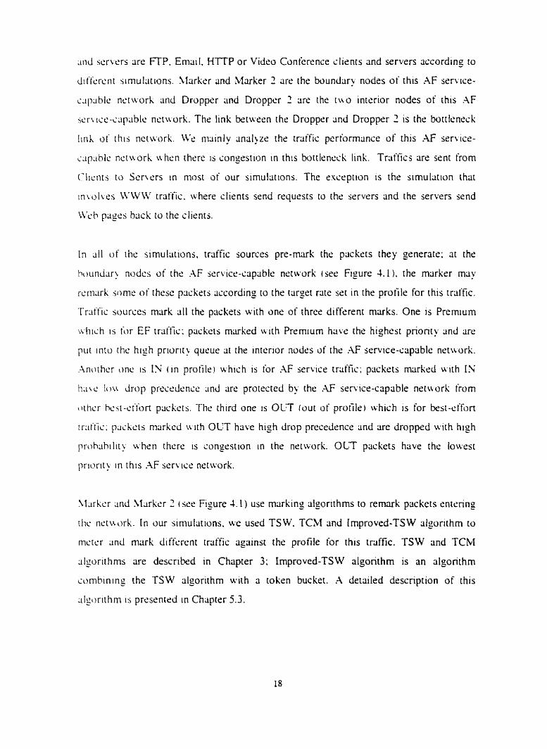
I f TCM alyrithm (141 is in use at the boundary nodcs. thcre wiII be a token buckct for
cach ut iriiific rhat the ISP 1s providing service to. The buckzt sizr and the token
Sencriitlon rxc for this token bucker are cornputrd bassd on the allowed bursr size and
th2 t~ir2c.c t-31~' o i t h~s tr3ft-i~ [ha[ are SC[ In the profile for this traific. When a Premiurn
pask t cnicrs a boundar~ nodr and thrre are no tokens in the token buckst. this packet is
droppcd. Wlicn an IN packet cntsrs rhe boundiiry node and therr are no tokens in the
roken buckct. this p;icket 1s rcrnarked as OLT packet. Otherwise. the packer u I I I enter the
.-IF se r i ~ c c - c ~ P ~ ~ I c nctu ork u ithout ;in! changes.
Figure 4.1 Boundary Node of A F Service-Capable Network
hl1 thc marking iiigorithms do not monitor OUT packets that enter the network. This
means that the pcickrts crin only be remarked to a l o w r priority but never rernarked to a
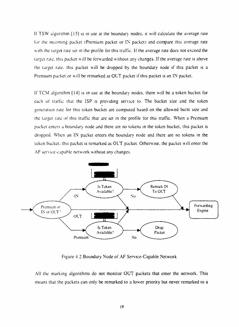
highcr priority ;it rhe boundary nodes. Fisure 1.2 shows how a boundnry node manages
;il1 r pc.; d i m i l i c h) usin? TCh1 algorithm.
Fipurc 4.2 .;hotir th21 rhcre ;ire tua tokcn buskcts 1it the boundliry node One is for EF
scr i 1i.c i r l i i ' t ï ~ 2nd .inothcr onc is for .* servicc rraffic. R'hen ;i packer w t h EF service
CS ~ n d [ h m ;ire noi snwgh tokens in the roksn bucket. this packrt is dropprd: this 1s
k,.iaujc the EF scr i~se triiffic is stnctly policed ar the rdge of the nrtwork [ I l [JI. Whcn
a piickcr u i th AF jsrii~s arrives and there are not enough tokens left in the bucket. this
pschct 1.; rmxirkcd ds OCT packet. OLT packets are simply fonvarded into the nrtwork.
Hi gh Priority Queue
' Pt-em~um or
13 ,Ir OLT" th or OLT Lou Priority Queue
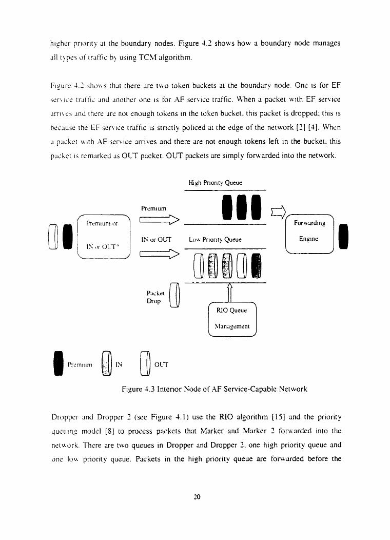
Figure 4.3 Interior Nodr of M Service-Capable Nerwork
Droppcr 3 r d Droppcr 2 (sec Figure 1.1) use the RIO algorithm [ l j ] and the priority
queuing mudçl [ S j to process paskets that Marker and Marker 2 forwarded in10 the
net u ork. Thcre cire two queues in Droppsr and Droppsr 2 , one h i sh priority queue and
one Ioa prionty queue. Packets in the high priority queue are forwarded before the
pd,cts In the Ic)n prmrlty queue. The packers in the loiv pnorit) qucuc: arc forwrded
1 u h m thcrc IS no pcicksts leil in high prionty queue (Le.. high priority queue 1s
crnpiyi. M'hm li p a s k t a i r h EF service (marked as Premium) arrives. it is pur inro rhe
high priorit>, queue; this 1s because EF traffic requires low deltiy and low deltty litter.
Psckeis LL ith AF service I markrd iis IY) and best-effort service ( markcd as OLT) are put
in lo lou prioriiy qucur; 1'; plickets have lower drop precedcnce than OLT packers. RIO
~lgorithrn has k e n implrmented in the low priority queue to manage IN/OUT.
B \ uimg RIO algorithm. 1N packrts have less chrince [O be dropped than OLT plickets.
~ n d therciori: proudes predicmbie lrvels of service to IX packets as long as thsy do not
L 1 0 1 ~ t ~ / ~ i ; i t ' d t t ~ ~ i . profite.
F p r c 4.3 show h u ~ pnonty queuing modci and RIO iilgonthm manage packcts
i&-v ;lrdcci into the netwrk.
4.2 MuIti-OS Dornain Network Architecture
[n th15 icxtion iw prcsent a multi-DS domain nrtwork architecture thlit wr used in Our
sirnullirions to mdyzdcornpare the results rvith the ones we obicilned runnins our
~iri iulri i iuns using ri single domain nrtwork architecture. This was motivared by the bct
r li;ir in rc4 aorld. wmmuniccirion systems rire oftrn cornposeci of manu inter-connected
d i i rn i~ im.
In the multi-DS domriin nctwork, e x h domin uses the same rnschanrsms, described in
Sccrion 4.1. to rnlinugs packrts of different services at the boundary nodes and intrrior
nodes. Figure 4.1 shows the multi-DS domain network architecture.
Thert: cire i ï v è inter-connected DS domains. In Domain 1 and Domain 2. there rire tlve
slitlnts ncirned Client 1, Client 2, Client 3. Client 4, and Client 5. ln Domin 4 and
Domain 5. there lire five servers named Semer 1. Server 2. Server 3, Server 3. and Server
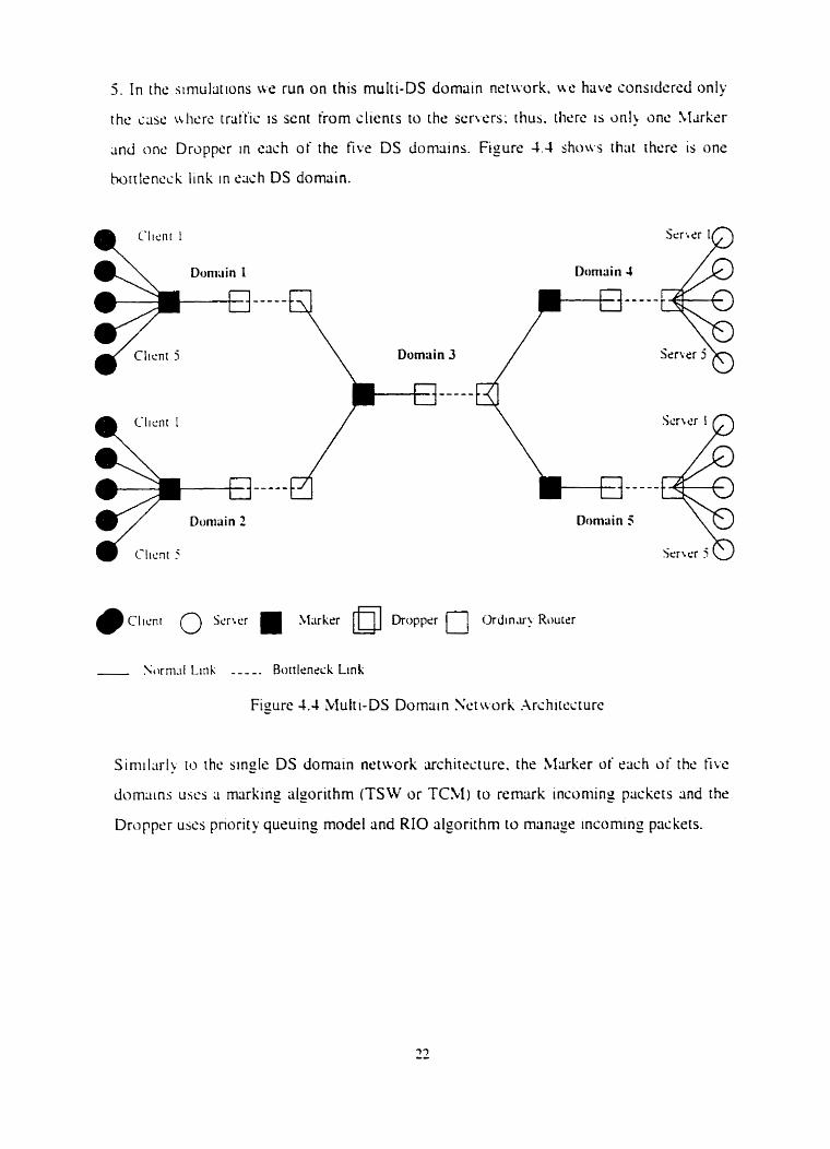
5 . I n the sirnul;itions u e run on this multi-DS dornain net~vork. ufe have considercd only
the case v.licrc tnitic 1s sent from clients to the servers; rhux. i h t x IS o n 1 onc Slarker
and onc Dropper in each o f the five DS domains. Fisure 4.4 show thai rhcre is one
hottlsneck link in sach DS domriin.
Clicni O Serrer Xlxkrr Dropper O Ordin.ir?Riwrcr
. Sorni.il L i n l - - - -. Bottleneck Link
Figure 4.4 bIuiti-DS Dornain Scni ork .~rchitscrure
Simil;irl> io the sin@ DS dornain network architecture. the Marker of cach of thc iïve
dorn~tins uses ii marking algorithm (TSW or TCM) to rernark incoming packers and the
Dropper uscs pnority queuing mode1 and RIO algorithm to manage incoming packets.
Chapter 5 Simulation Models, Results and Analysis
I n rhis ch;ipicr. Lie prescnt the differsnt simulations l ie prrforrned to evaluatc the
pcrformlince of .W rcrvicr-capable nerworks supponing differenr t'pcs of traffis. The
nerivork iirchitectures inrroduçed in Chapter 4 uere used to run the sirnullirions on. Each
section in this chapter presents rhr simulation rnvironmcnt t q . viiluss of simulation
paramctcrs). simulation rrsults and analysis for a siwn issue. This chapter is orpnized as
iolloir s ' . Section 5 . 1 evaluarrs the impact of CDP rraffic on TCP (ETP) traffic in AF
scrvicc-capahle neri\orl;. Section 5.2 ev;ilu;iirs the impact of CDP triilfic on TCP
i WVW i d t ï ~ in ;\F service-capable nerwrk. Section 5.3 prcsents ihe performance of
diffcrrnt blxkin_o hlgorithms when used in AF sen icr-ciiplihlr n c t ~ urk i cir boundriry
nodes 2nd proposes a new marking algorithm niimed Irnprovrd-TSW iilgorithrn. Secrion
5.4 studics bandwidth allocation issucs in .\F scrwe-capable nr twrk. Section 5.3
c \ i i l u ~ t c s the Impact oi tTCP) Round Tnp Time in the pcrformansc d i .\F service-
c:ipiihic. nctu orh. Srct~on 5.6 tackles the issue of supponing EF 5 r . n [ce traffic in .-\F
w-1 icc-aiprible nettwrk. Section 5.7 evaluares traffic performance in 3 multi-DS dornrtin
nctwrk. Fincilly. section 5.9 concludrs the chapter.
5.1 VDP traffic and TCP traffic (Infinite File Transfer) in AF Service-Capable network
I t is 3 faci rhat LBP rraffic takrs almosi (111 the link ti;indu idth ~vhen cornpetin_o with TCP
rriiftïi in r d a < s kst-effort netivork. [ndeed, a TCP source btick-oifs i 1.s.. decreascs its
throughpiir) d w w v e r i t SURS losing prickrts <i.e.. disctirdrd by muters, rrhilc UDP
sources continue to wnd packets at the same rate w r n i f there are packets losses.
In our .G srrvm-capable network isee Figure 4.1. Single DS domain nrtwork
iirchirscturr.). u.r will mark TCP packets with a low drop precedence and LDP packers
iv i th a high drop precedence cit the boundxy nodes oiour DS single domain. Thus. whsn
rhere 1s congestion in the network. L;DP packets are dropped first. This will allow us ro
control CDP sourccs from gcttiny mure than thcir fair =harcs of netuork resources and
proteci TCP iraffic from CDP traltic.
. A m ~ i i l l ~ . rhsrc ;ire t ~ o k~ncl i o t TCP trdfic: ( 1 ) long-iiwd TCP connections. suçh ris
FTP: dnd 1 2 5hon-liwd TCP connections such ;is X e b trliffic. In this section. \r e present
the sinlul,iric>ns (se run to etrilutite hou, CDP trrit'fic affects TCP trriffic thrtt consisrs of
loris-livcd connections in ou r hF service-capcible net~wrl'; FTP trrilfic 1s used as TCP
tr;iffic. Files are rriinskrrrd infinitcly cifrrr connections h;tw k e n establishçd.
Configurations
The nsiuork circ.hiiecture sho~rn in the Figure 4.1 is uscd. Traffic is sent from the clients
to the wrwrs. Client 1, Client 1. CIiént 3. anci Client 4 are FTP clicncs tvhile Client 5 is
an emriil client. Ssrver 1 , Serves 2. Servcr 3. and Scrvèr 4 are FTP servers while Ssrver 5
1s sn riiiiliil 5crvc.r. The rcrisun khind of this clioicc i s thlit ihe FTP traffic is rhe main pcin
o i the tord traific in this sirnu1;ition and the Email 1r3itïc 1s just rhe background trnffic.
Tr~tr'iic. 1.; icnt (rom Client I tu the Scrwr I ( 1 <=i<=5 i. FI'P trritfic use TCP ris transpon
proiocol .inci cmail rralfic use CDP lis o rransport pnimciil. ; \ I l the FTP clients have ihe
s;ims c.untïgur;ilions. Sincc trailic is sent (rom clienrs to wrwrs. rhcrc sre oniy
ackii~iu l d g c r n m s sent from s s r w s ro clients: thc size of these ~icknowledgements is
ter\ 5m;111 1 0 C ~ U S C lin! congçstwn in the links (rom the scr\.srs [ci the clients. Thus. we
sonsidcr only Droppcr (sce Figure 4.1) sincr II is thc ciccess no& to the bottlrncck link
frum thc ilients to rhe scrvcrs. RIO algorithm 1s uscd bu Droppcr anci marking lilgonthrns
arc iiscJ b\- I\..I;irkt.r uhich is the buundary node oi th is .AF servtct: nstwork. We assume
t hat dl thc ;icknui\ Irdgements are jcnt (rom serrers to clients uithout losses.
Basic Simiilrit ton Confiourations
Thc fullo\vings are parameters thar lire used in ail sirnullitions presrnred in this chapter.
Srmultitions rire run for 1000 seconds in OPSET; it 1s the time nesdsd for the network to
bc. .;i;iblr. i ' a l u r s for IP packet and TCP segment size are the dcfrtuit values set in
GPSET -4ppi1i;ition q r n r n t airs 1s ihe miiumum sepicnt s i ~ s thc appliclirion laver san
bcnd tu f t~c I ~ i w r Iiiyer. Application srymrnt jire should nor h<: wo big: othrrwise. it uill
r . i k niorc rinie for scndrrs ru ii;igmcnt it and if one fragment in this segment is lost.
I - C C C . I ~ ~ S N I I I nut recciïs the uhole application segment. Application segment size
hhould riut bt. roo srnaIl rithsr; oihcru Ise. the system rlf'iciency will suffer (k..
un;ic'cr.pthlc proiocol overhcad). We sslsctrd a value of 9000 bytes for the application
icgrncnt iizc. pp1ic;ition sran rimc is the rimc the application stans sending packrts: we
use thc OPXET ilef~ult d u e rhiit is equal to 100 second. This rnrans the FIPlc-mail
trlit'tïc 1'; jcnt out aitèr 100 jctconds simulation tirne.
FPP Clic~ir .-lm-ihutc
EL cry FTP i licnt gcnerrirrs rr;itfic ai rats èqucil to 30Kbps at the application layer. This
1.; thc r w ihc ISP W H try ta MIS- for evcry clienr. Ler us noie that the m u a l triiffic
i W . . triiific in thc n r i w r k ) uill be a littlc bit cibove 30Kbps u,hen rve iake into account
TC'P ancl IP hc:~Lit'rs. The average file aize should not bc too smdl; orhmvise. there will
k man> . ;nidi T-TP ~icknowlcd~rments and requssts in the network.
FIIC Trmifcr Rare: 000 filrs/hour ( modcled usmg a Poisson distnbution )
.-\wriigc File S m : i 5000 bytes (modslrd using a normal distribution)
Thc Emai 1 clicnt genertiirs rraffic 31 3 ntr squal to SOKbps at the application layer. Let us
note t h ~ i thc acrual traffic (1.e.. tratfic in the nciwork) will be a little bit above 8OKbps
u hcn nc t ; i k inrci xcount LDP and IP hriiders. Email trrtffic uill not h w e a profile ar
t hc hounc tq n d c of our DS domain. The total amount of TCP and L'DP triiffic wI1 k
I;irgcr [ h m the handir idth o i the bottlrnscb Iink o f rhe netu-ork. The objective is ta
c.t;ilu;irc. r lic iriiiiis pcrtjrrnmçe o i all t hsse types of rriiitic undrr songest ion.
Send R ~ t c : l8OO nitxci~csihour i modclrd using 3 Poisson distribution)
A wriige E mai l S I L C : 20000 bytes i modsled using 3 normal distribution)
For i i ik~ ' \iri~pliili>.. w ;issume thltt J I l inks encept the bottlrneck link have enough
handuidth to ~scornrnodiitr. all tral'fic p è r a t e d by client or servrrs. Wc set the
h m d w i i h c;f the botilmecl link tu LjOKbps: the total traffic will be obove ZOOKbps.
This scrting wll iillou us to malyz r the trciffic performance of AF service-capable
nctu.ork n hm the wngcsrion is sucre.
Thc txgc.1 m e IS the irxtion of FTP trat'tic the ISP 1s willing to protrct. Actually. FTP
s1icnt.j. ~ltogc.thcr. uill gcneratc lt rraific of a rate cqual to 120 Kbps at the application
la!vr TSW s l p m r h m will use this tarzct rate to mrtrr and remark the FTP tmffic. When
ihc targct riitc is caiesdcd. irisoming packers will be remarked to OUT packets.
Target Rare: 1 Z0000bps
Thc CIR IL; rhc buckst rsfrssh rritt. for the t ~ k e n buckct. We use CIR to rcprcsenl rhs
ix;c.i rare tor the FTP iraific. Li's set the buçket s i x to indic;ite ho\\ many bursts o f ihe
FTP traitic i s ;illowd to enter the nt'twork.
Brishct Sizt.: 64000 bits
CI R . 1 70000 bps
Irnpro\r.d Timc S l id ing Window ,\lgorithrn 1s a ne\\ marking alporirhrn that combines
T S X dlgiiriihm ~ n d t o k n buckct: detailrd description of ~ h i s algorithm is prrsentrd
i n iciiion ï . 3 The rcirgctt rare is set for TSW ;ilgorithm and ihe CIR and Bucker Size are
f o r the tokcn hucket.
Thc bcttings of ihe piirrimt.ters of RIO dgonthrn are riirned to produce sirnulritions u herc
OLT p~ichets hale highrr dropping probnbility thnn IN prickets. We set the thresholds for
OLT p;izk.cts to tx ver? low in ihis simulation: dl incoming OLT pitckets wili b<l
droppcil 1 t- rhc iiirriiyc queue lrngth is above 30 prickets.
Drop Prohtrbiiity for 19 Packers (Pm,-,.): 0.03
Drop Pr~\hiihi l i ty for OLT Pÿckets (Pm,-&: 0.08
\Icrxirnun-i Thrcshold tor IX' Prickets (mm-in): 10 paskets
JI;isinium Thrcshold for OLT Packets (mrix-out): 30 prtckets
~ I i n i m u r n Threshold for [N Prickets (min-in): 20 packets
Minin iurn Threshuld for OUT Packers (minout ) : 10 packets
Results and .-\nülysis
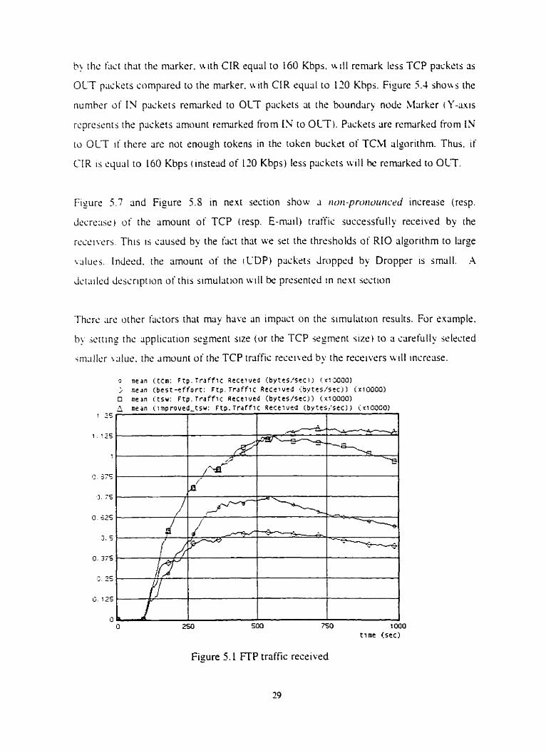
In Figurc 5 . 1 c resp. Figure 5 . 2 ) the curve named kst-effort quliniities the amounr of FTP
mitic (resp. Ernail traftici succrssfully reccived by the recçivers in k s t - ~ f f ~ n nctwrk .
The curves nrimed (cm. rsiv and improved-tsu quantifies the amount of FTP trtiftk (rcap.
E m u l trliffic 1 succsssiully rrcrived by the recrivrrs in .\F service-capable nctwork using
1'C)rI rilgonthm. TS W rilgorithm and improved-TSW (at the boundary nodr of rhe DS
domain) respcctivrly.
Figurc !. 1 shcm s that the Iimount of FTP rraffic. succrssfull) receivcd b) the reczixrs.
h3s increiised using AF service-capable net uork instead of best-efton nstwork i Y-axis
rcprcjcnrs th<: Jmount ot FTP traffic thor has bern succrssiully trrinskrrsd: the unit u i Y-
. i w i 15 IOOOU ' byrs /sec i . In opposition. Figure 5.1 show thar rht. mounr of ihr E m d
trii tfic. i uccc~s iu l ly reszivcd by the receivsrs. has drcrraazi usiny AF service-capable
nciwrA i n 3 t c . d of ki t -ci ton network (Y-cius rrprrsenrs rhe rimount d Erntiil triiffis thai
hLis ksn S U C C ~ S S ~ U H ~ trrtnsferred: the unit of Y-iliris is byteslses). Basecf on thsse
ohm-\ ci i ic ini u c can statr. ihat the TCP traffic h;is k e n prorecied in AF s c r ~ ise-capable
ricin o r k irorn rhc non-îdaprivr CDP trat'fic.
The degrce o i incrctise of the amount of TCP traffic and the degree of drrrease of the
sninunt a i C-DP rraffic successfully received by the receivers depend on the wlues of the
parlinierm d the m u k i n g rilgorithm. in use. and RIO algorithm. To verify the impact of
rhc w lucs o f rhese parameters we run similar simulations but with diffcrent scttings.
Figure 5.7 shuws results of sirnilar simulations we n in but wi th 3 different value of CIR
q u i i l to 160 Kbps (instrad of 110 Kbps used in the previous simulations on TCM
niarking ~i lpr i rhrn) . Figure 5.3 shows that the amount of TCP traffic received by the
rccclvers I S b~gger compared with the results of the previous simuliitions. This is c3uscd
ti) t hc Lict that the mlirker. N ith CIR e q u d to 160 Kbps. \r i l 1 rcmark less TCP packers 3s
OLT plickcts compared to ~ h e m a r k N ith CIR equcil to 110 Khps. Fisure 1.4 shoit s the
numher of IN paskrts remrirkcd to OLT packets at the boundriry nude Mrirkrr t Y-am
rcprcscnts rhs plicksts amount remarked from IN to OLT). Packets are rcmarkrd from IN
10 OLT I I thcre are not snough tokens in the token bucket of TCM algurithm. Thus. i f
Ç I R 1s qua1 to 160 Kbps (instead of 120 Kbps) less plickets wili h<: remarked to OLT.
Figure 5.7 and Figure 5.8 in ncxt section show 3 t i m - p n ~ w i r r i c c increue (resp.
Liccrccisr., of the amount of TCP (resp. E-mail) rraffic successfully received by the
rcccilcrs. This 1s uusrd by the fast that w r set the rhresholds of RIO algorithm to Iiirge
u1uc.s. Indred. the amounr iif the i CDP) piickets ilropped by Dropprr is jmiill. .A
Jcriiilcd dcssription of this sirnullition will be presentd in next section
Thcrr: are other iiictors thlit may have an impact on the simulation resulrs. For example,
by icrting thc ~pplication scymenr su r (or the TCP segment size, to ri ccirefully wlectrd
jrnii1lc.r uluc. thc ,.imounr of the TCP triiffic rrccived by the recrivers K I I I incrccise.
Figure 5.1 FTP traffic received
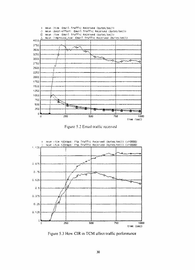
l 000 rime (sec)
Figure 5.3 How CIR in TCM affect traffic performance
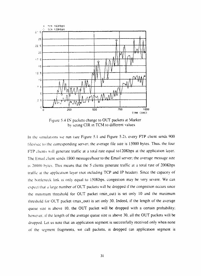
Figure 5.4 I'; packers change to OLT pnckets or hlmker by jctin_o CIR in TCM ro different u l u r s
In ihc .;iniul;irioris LW run (sec Figure 5.1 and Figure 5 . 2 ) . rvery FTP client sends 900
i'ilc.s/icc ru thc currcsponding w w r : thc average file sizr is 15000 b'es. Thus. thc four
FTP ilicnrs u i l 1 gcncrate traific ~ i t a total r;ite qua1 t0120Kbps iit the application loyer.
The Eni;iil i l i ~ n i sen& I SOO mess;iges/hour to the Emtiii server: the avcritgc message size
i i 20000 h!rcs. This means that the 5 clients senerate traffic ai a rotcil rate of lOOKbps
triit'tic d t rhc qplicstion la)rr (nor including TCP and IP brader). Since the capaciry of
rhc h ) r r l r . n d Iink is o n l y squîl to 1SOKhps. congestion rnay be \,ery ssvrre. Wc con
c . \ p x t [ t u t J Lirpc. number oiOLT packers uill hs dropprd if the congestion ossurs since
the rnininiurn threshold for OLT ppncbet (min-out) is set only 10 and the maximum
threshold t'or OLT pcicker (mm-out) is set only 30. Indced. if the lenoth - of the average C
qucus sizc is above LO. the OLJT packet will be dropped with a. cenain probnbility;
Iio\reir.r. i f the lrngth of the average queue size is above 30. al1 the OUT packcis ~ v i l l be
droppcd. Lct us norr that ;in sppliciirion segment is succrssfully receivrd only when nonr
ot' the wgmsnt fragments. we cal1 packets. is dropped (an application segment is
riicnrcd 11' ihri trlinspon systrm cannoi handlr a packet o i this sizc 1: rhis explains the
I I Jmount o i Emul tranic received hy the Email srrvrr.
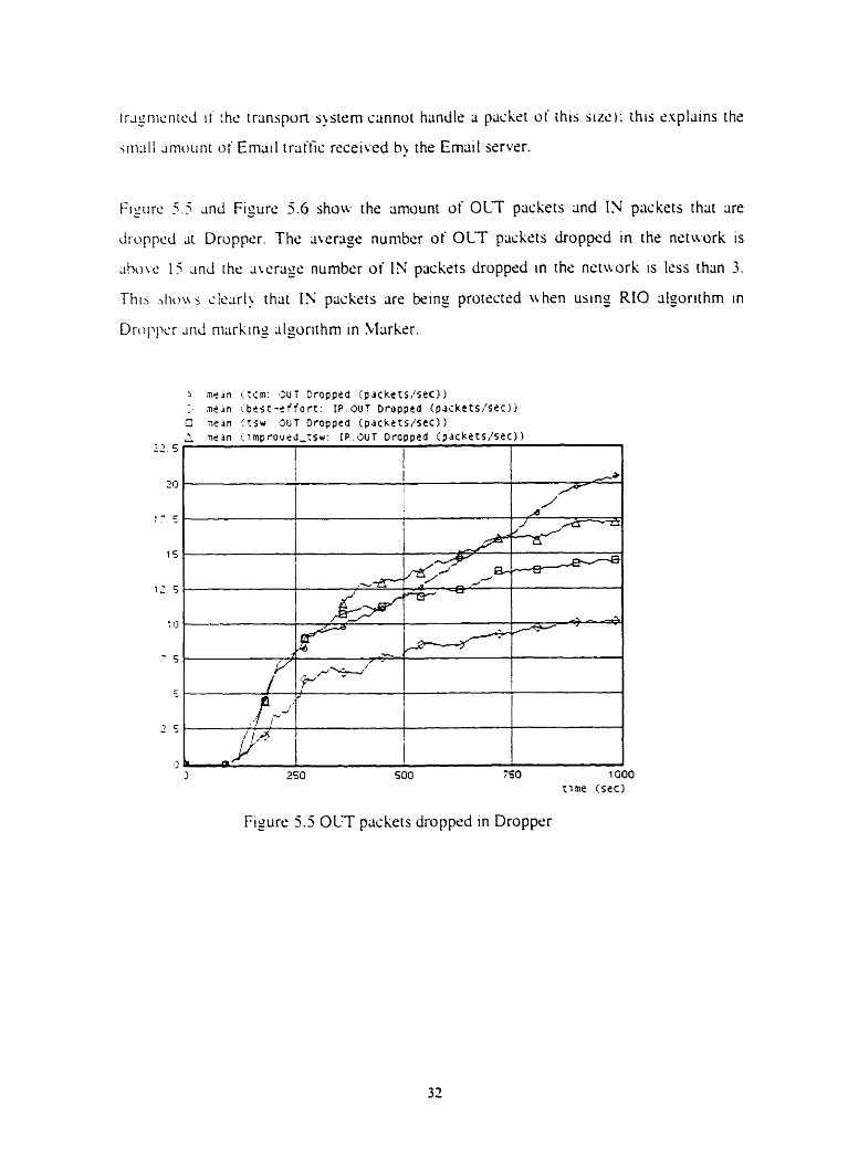
Fisiire 5 .5 ~ n d Figure 5.6 show the amuunt of O U paskets and IN pückets thrit ;ire
iirupped dr Dropper. The average nuniber of OLT packets droppcd in the network is
;iht)w 15 ;~nd the dwrrige number o i IS paçkets dropped in the nctwork is Iess than 3.
Thi i i hou z: clcari) thar IS paskets are k i n g protectsd whrn using RIO algorithm in
Driippcr ~ r i d niarking ;ilgorithm in Marker.
Figure 5.5 OLT pxkets dropped in Dropprr
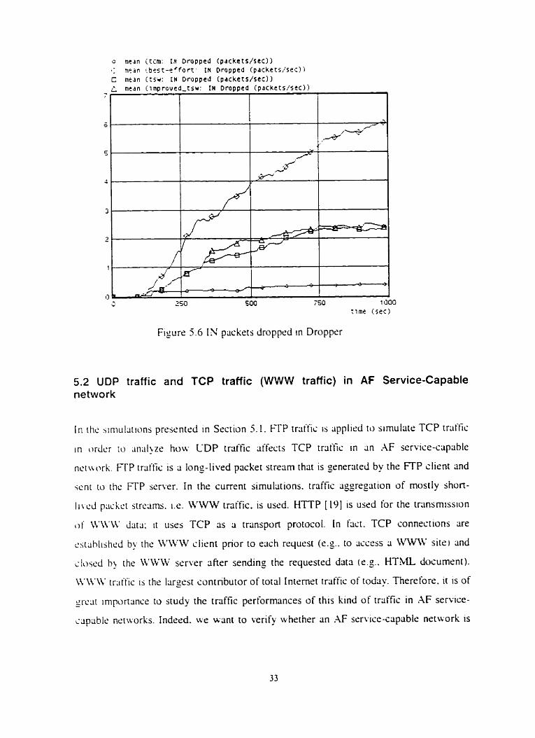
F i y r r 5.6 1s packrts dropped in Dropper
5.2 UDP network
In thc ';in~u
traffic and TCP traffic (WWW traffic) in AF Service-Capable
iitions presented in Section 5.1. FTP traific is ~ipplird to sirnulair TCP trriffic
in or&r ru ~n;tlgr hou CDP traffic affecrs TCP trriific in an .-\F service-capable
nctwirk. FTP traffic is 3 Ions-lived pricket stream that 1s generaied by the FTP client and
wnt to thc FTP server. In the curen t simulîtions. traffts aggrepatlon of mostly shon-
Iiwd p;icLst strciims. 1.e. WWW traffic. is used. HTTP [ 191 is uscd for the transmission
of IW 'M ' daid; it uses TCP as a transpon protocol. In fx t . TCP connections are
cs[;ihlijhr.d by the \VWW client pnor to each rrquest (cg.. to acçrss î WWW site) and
ilcised h> rhe WWW sert.çr iifier sending the requested data (cg.. HTML dosumrnt).
XW\ï tr;iific is the hrgest contnbutor of total Internet iraffic of today. Therefore. ~t is of
irciir importance to study the tnffic performances of thts kind of trafic in AF serviçe- - ccipablr nris.orks. Indesd. ws wsnt to verify wherhçr an XF service-capable nrtwork 1s
iihlc 10 provide the s;ims assurance for WWW iraffir: as i t did for FTP triiffis (sec Section
5 . 1 ) .
Thc. ncruurk archiiecture shown in the Figure 4.1 1s usrd in the current simulatians.
Tr-litfic is sent t'rom serters to the clients. In these simulations. Client 1. Client 2. Client
3, and Client 4 are HTTP clients ~ v h i l e Client 5 is an ernriil client. Ssrver 1. Serwr 2 ,
Scrwr 3. anci Server 1 are HTTP seners whtk Server 5 is rin srnail scrver. The rerison
khind o i this shoicr 1s the WWW rraffic 1s the main pan oi the total irriffic in rhis
riniulsiion ~ n d rhc Emriil traffic is psr the background traific. Client i ( I<=ic=4) sends
rcquchts to Serwr i that scnds WWW traffic back to Client i. L W . " trciffic uses TCP 3s ri
trmspun prorocol and rmiiil trriffic uses CDP as a transport prorocol. Sincr ail the trcitfic
I S wnr t'rom serwrs to clients. there are only trtiffic requests and acknowkd~ments k ing
,snr rrorn clients to servers. The sizrs of rhrse requests and ~chnowledgrrnents are wry
\mlill: it 1s redistic to asurne that they will cause no conprstion in rhe links from the
clients to t hr suvers. Wri only considrr the router Droppcr 2 hrr Figure 4.1 ) sincc this
rcitiwr is the ticccss router to the bottleneck link tiom the scivers to the client. RIO
.ilgorithm 1s used by Droppcr 2 md TSW muking algonthm is uscd by Marker 2 ~ihich
i i the hwndlir) nodi: of this AF srr~ice-capiibls netuort. WC assume thtic dl the
Lii h n o u ic.dgt.rnt.nis x e sent frrurn clients to seners without losses. Tu run our srmulations
LW nwd to configure 311 simulation parameters. Sornc parameters have the snme values 3s
t h s i r pwrs in ihe simulations prrsrntcd tn Section 5.1. Thsrdore. only paramerers that
i - w c di t'krcnt irriluss rire lisred below.
Dcfault configurations are used for image browsing. sscirching and heavy browsing in
OPSET. P q e rate is rhe rate at which HTTP clients request HTML pages. Page size is
the iota1 sizs of HTML objecrs rrtrisved through a single page iiccess. Mm Connection is
1htl mciximurn number of simultaneous TCP connections used by HTTP clients for
iommunic3tion with HTTP servers. Calculations based on the parameters* values listsd
k l o u rçveril that the total volume of traffic from the W W V srrvsrs significantly exceeds
150Khps - thc banduidth of the botrleneck link in the .AF service DS domain. I r is highly
lihsl) that scverc consrsrion in the bottleneck link will ocsur in ihcsr stmularions.
Pa-c RLIC': -760 p+es/hour ( modclrd using ;in ecponentilif disrnbut on)
Parc Sire: 1 objcst1p;igr i mudslsd using an cnponential disrribut ion 1
.beriigs Objrct Size: Irnase t 100000 byres/objrct) (modrled usins an cxponentiai
distribution i
11ti.x Connectton: 4
Since R'M'W traftic genertited by K l T P servers is greatsr than 150Kbps and the
oet rrite CO hott lsncck link e t this hF servicr-capable n ç r w r k is 15OKbps. ws set the t a ,
t.t. I MEibps for the TSW algorithm. This irnplirs that only 1 5OKhps of lVW triiffic will
Wr. usign h i s h values ro the rhrcsholds d i IN 3nd OLT packsts for RIO algorithm in the
ciment simulations. This is difkrent from the srmul~tions. prescnted in Section 5.1 .
~rhcrc :rc ssigned Ion values to rhe thrssholds. Bu doing so. u e mticipiitr different
resulti in th15 sirnuiaiion: lsss OLT prickets will tx dropped and the TCP triit'fic
succrssiull~ rccecvcd by the recei~ws wII not bc improved as much as the simuliitions in
thc prwious scct ion by using .4F service netirork.
Drop Prohahility for IN Pxkcts i Pm.-,,): 0.03
Drop Probribility for OUT Packers ( O.OS
\I;itinurn Thrcshold for IN Packers < mu-in): 55 packrts
hI;i.cirniim Threshold for OUT Pxkets (mal-out): 50 packers
>lininium Thrcshold for [ Y Packsts (min-ln ): 40 pxkzts
hlininiiini Thrcshold for OLT Packers (min-out I : 33 packsts
Qucuc WC tg ht : 0.002
Qucric Lcngth: 60 packet5
Kesiilts and :lnril~sis
in r h w .;iniulations. only Timr SliJing IVindotr iilsorithm anci RIO cilgorithm arc used to
mcier ; i d mark traffics 31 the boundiiry node .\Iarker 2 ~ind Dropper 2 rrspc.ctivrly. The
surw nanicd tsii-WWW represrnts the trciific recrivrd in the Al? service-capable
n b using TSW algonthm ai the boundary node. The curvr narned best-
ciCm-t-lVWW repressnts the traffic reccived i r i the kst-effort network. Fisure 5.7 shows
thar the WWW twffic successfully recrived by the HT?P clients is improved in .4F
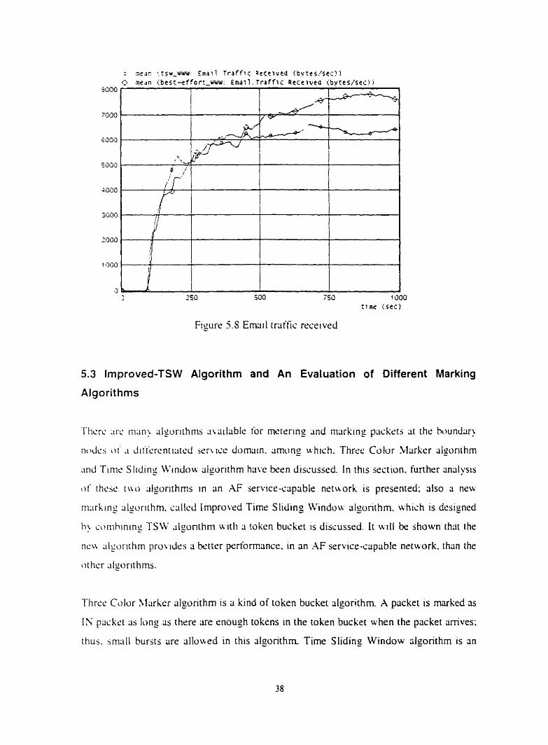
scniçe-ccip;iblc netviork. Moreover. from Figure 5.8. we can leam rhat Email traffic
suc.çcsstull~ receivrd by the Email client is reduced. Howrvrr. sompared with the
sirnullirions presented in Section 5.1. the protection of WWW traffic from LiDP traffic is
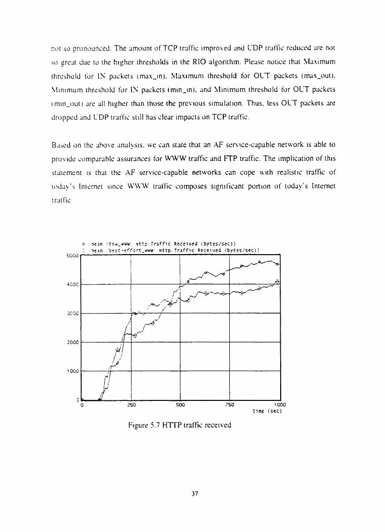
noi sc, proncunsd. The Iimount of TCP traffic irnprowd and CDP trltific. rcduccd arc n ~ t
.;a greiit dur 11, the higher thresholds in the RIO iilgonrhm. Plcase notice that !vIa.timurn
thrcbhold i,r IS pcislet~ ima.r-in). Maximuni threshold for OLT prickrts (mou-out).
Minimum rhrcshold for 13 pachsts (min-in). 2nd 'rtininium ihreshold for OLT pcickcts
i min-our ) arc 311 higher thon those the prcL ious simulation. Thus. less OCT pockets s e
d r u p p d 2nd CDP triiihc wll hlis clelir impacts on TCP trliffic.
B,iscd on the ahove ;inlilysis. we u n state thlit an .V service-capable network is able to
providr: comparlihlc assurances for WIVW rraffic and FTP troffic. The implication of'this
itatcmcnt 1s rhltr the AF service-capable nctworks crin cope with redistic iraffic of
t~>d; iyl i Internet iincc WM'W traffic cornporcs sipnificanr ponion o i today's Internet
t rltf'fic.
Figure 5.7 HTïP traffic recrivrd
250 5 O0 755
Figure 5.S Ernüi l traffic reçeived
5.3 Improved-TSW Algorithm and An Evaluation of Oifferent Marking
Algorithms
'fticrc Lire man) alporithrns awlable for mctsring and markin- paskrts î t rhe houndar!,
i i ~ d c i ot* a Jiit-crcntisrcd w u s e domciin. m o n g uhich. Three Colvr Marker iilgonrhm
iinJ Tinis Sliding i i ' indo~r algorithm have k e n discussed. In this section. funher linlilysis
ot' thcsc t t to aigonthrns in an AF service-capable network is presented; ais0 ri ne&
n i x k i n g alsurithm. sitl1r.d Improvrd Timr S liding Windou* algorithm. which is drsigned
i>> i o n ~ h i n i n g TSW algon~hrn uitli a token bucket is discussed. It will k shown thsi the
ncn iiigurirhrn pro\.idrs a bctter pertommce. in an .IF srrvice-capable neiwork. than the
o t her algorit hms.
Thrcc Color Marker algorithm is a kind of token bucket algorithm. A packet is marked as
IS packct 3s Ions as there are rnough tokens in the token bucket when the packet amves:
ihus. snicill bursts are allourd in this algorithm Tirne Sliding Window slgonthm is an
wcriige ratc estimator. AS Ions ÜS the plickrt's avcragc rate docs not exceed a subssribed
r;ite. 1.33'Rr in this sirnullition. the ptiçket 1s markrd as 1N packri: otheruise. ihc packet
is insrked a2; out of profile pcickets. Since al1 the packets whosc riverage rate is above the
suh.;crihc.d rrirs Jre marked as out of profile packetj. bursts are no1 ; I I I o u ~ L I in this
slgoriihni. In rliis stxtion. the simulri~i~ns ur prescntcd in section 5.1 are used to euluate
the pc ' r formanxs o i differeni mxking algorirhms.
750 1000 clme ( s e c )
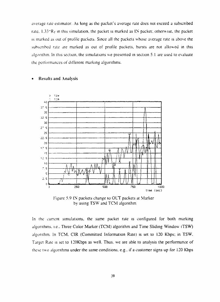
Figure 5.9 IN packers change to OLT packets at SIrirkçr by using TSW and TCM algorithm
I n rhc iurrcnr simulîtions, the sarnr packet rite is configured for both rniirking
dgorithms. 11.. Threr Color Marker ( K M ) algorithm and Time Sliding Window (TSW)
~lgurithm. In TCM. CIR (Committed Intorrnation Rate) is set to 120 Kbps: in TSW.
T q e t Raie is set to 12OKbps as well. Thus. wr.r are able to anÿlysis the perfomance of
r herc i u o ~ I~on lh rns under the same condirions. cg.. if a customer signs up for 120 Kbps
Figiirc 5.9 shuirs the nuniber of IS packrts rerniirkrd to OLT pcickets (it the boundary
ride J1iirki.r using these tuo ;iljorithms. Ln these simulations. ue senerateci vcry bursty
tr;it'fic. Alrhough the TCM algorithm ;illou.s bursts in the triiffic. it tolerates only small
biirsts. Ii ihc rraffic burst is very high. l x . . the priik rate of the traffic is much higher than
[hc wbscriticd rate. the bucket ofTCbI algorithm wll bccorne full very quickly. Then the
upconiing IX pciskets uill be rernarkcd 3s our of profile packets. Figure 3.9 shows that
u hen i img TCM algonthrn IN packets change to OLT psckrts conrinuously. The reason
kti i i id [hi.; I > ihat itic r e sowy riitr o i rhc huckct in TCM algonthm 1s only IIOKbps. but
the pcak r;irc. I L . hurst. of the iraifis is much highcr than 120Kbps: funhrrmore. the
.rcncrxc.d tmific inducles a large nurnbcr of bursts making the bucket "a luys" full when - p:ickc.ts mir-r. .A w l u t i o n is to incressr the buckr.1 s u r in TCM VIO ;illou bisser bursrs in
thc trciifis. This is bcisd on the cornputati~n of the hurst s i x : Bursi Sizr = CIR * T + B u i k ~ r S i x ir h m T is thc tlmc for the hurst. Scwthc1c.s~. since the CIR 15 yenerally
rtiiic h I owr than ihc pe~ik rare (burst of rhr iraflic.. the rccovcry raie of thc buckrt will lx
; r i I l niiich Io:w ihm ihe peak rate. Thcn. aftcr rhr bucket rexhes its full. the upcoming
pltcksrs wll be rcmarked continuously although the hucket s ~ z r 1s bigger than bcfore.
Figure. 5.10 shoiti the mcan value of the numher of pxkets that change from IN to OLT
:it houndiir> nudc Marker with buckct sizes of 6 1 K and 160K respectively. Aftrr
incrclising the buckct size from 64K to 160K. ferrer pückets are remarked to OLT at the
II:irhcr. t-Ioucver. the rate of IN to OUT is siill high; Rare of IX ro OLT = total packets
rcnicirkd t'rom IS to OLT I total I ' I piickets. Figure 5.1 l illustrritrs rhat the traffic
pcriorrn;inc.c: i i i rh the buckct size of 160K is slightly hetter than the trriffic performance
w t h b u c h sizr of 64K. However. increcisinz rh r bucket size does not improve the
i)crt;)rmsnc~~ 2s much as incrc;isin_o CIR (see Figure 5.3)- Futthermore. increasing the
buckrt sizs ri'quircs more system resource (mcmory) of the router.
.k tua l l \ . thrre are two techniques that can be used to improve the traffic performance
u h m using TCM algorithm.
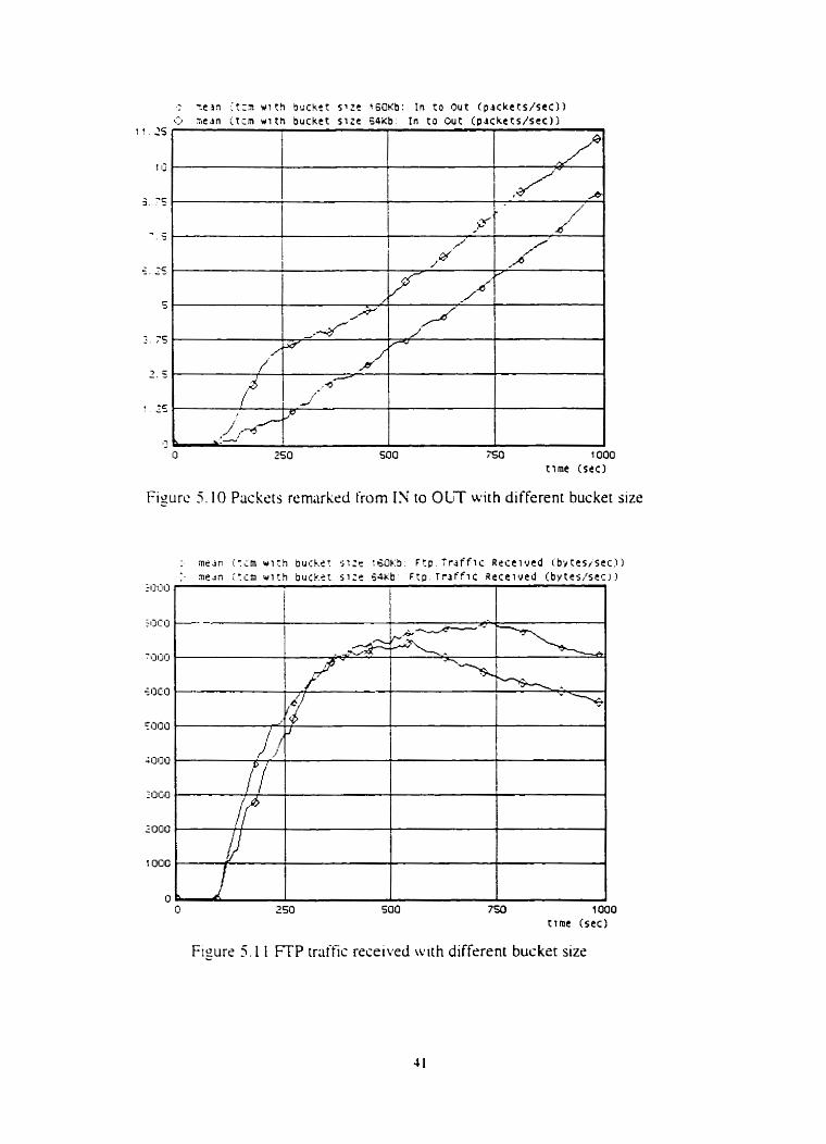
Figure 5 . 1 1 FTP rraific received with different bucket size
K i i h [tic iirst technique \ te should Irt the packcts pass a shoper M o r e entrring the TCSI
rii;irLcr. B I u m g ii sh~ipcr. both the burst s i x and the peak rate of the tr~ii'fiî are undrr
n r Anorhcr one or two tokrn buckets (one toksn bucket is used in TCM algorirhm)
i ~ n i b i i i ~ d u i ih rhis shitpcr u.ill d lou to control the traffic's burst size and peak nre.
.\fier p w i n g rhr. shriper. the traffic will not have big bursts; thus, kwer packets uill be
r c r n x k d ri) OLT whrn using TCM algorithm. At the m a n time, we c m k t trriific with
lou hurjt enter rhe A F service-capable nrtwork to release the burdsn of intrrior routcrs
i cg . Icss huifer s ~ z e mtiy be usrd in intrrior routers). This will help the traffic behwior
into thc. .-IF .;cruce-capablc ncruork to be mors predictabie. For exiirnple, in our currrnt
iirtiiilstiani. sien :i \ L e mark a burst of 1'; packets into our AF service-capable netu,ork.
riic iS p r i i k ~ t W H likcly be droppcd tn the inrsrior nodes because of resource. 1.e..
hur i~rs. j h i ~ r ~ a g ~ Jr the Dropper (queues arc ful l ) . Howvcr. i f we remove the big_ bursts
rrom rhe tr;iific. using a shaper. this problem w I I disripprar. A shsper will tx iidded in
h m oi' thc m;irker. to improve the tralfic pcrform;ince of the AF service-capable
nctu o r k . in w r iurure sirnulrit ions.
\I\'iih thc a u n d icchniqut. u e should use two token bucksts (instcad of one) cit thc
IwunJar! n d c s rc, mctcr 2nd mark traffics. One buçktrc is used to control the average rate
~ j r ' (hc ir)rning trtlffÏi: thcre is only one token in this token bucket. The CIR of this toksn
I~i~cIict i j the JL c r a g c r m of the traffic. When a packet amvss and there is a ioken in this
r d x n huchct. rhis packet entçrs the M service-capable nrtwork without passtng the
jcconcl mkcn buckct: «theni ise the packet enters the second token bucket. The second
[ohm hudct IS uwd to control the bursts of the cominz trafic; the bucket size of the
sccond tohcn busket controls the burst stzs of the trdfic and its CIR conrrok the
ircqiicnr~~ of the hursts in that trriffic. If a packrt rnters the second token bucket and thrre
Jrc no snough rokrns in this bucket. the packet will be remarked as OUT packet. By
u m g r L t o toksn huckrts to meter and mark traffics at the boundary nodes. we should get
k t t c r tritl'ris performmx.
Figure 5.9 shows that much fewer IN packets have been remsrbed to OUT packets by
using TSW slgonrhn thnn TCM algorithm; in fact. in TSW algorithm only the packets
i r i ih the Jwragc rate above I.33*RT (1.33 IXKbps) are remarked 3s OLT pcichzti
Thc hursis of 1'; plicliets uhose rate is below 160Kbps pass the Marksr nithout
i-cntiirking. Figure 5.9 dw shows thnt al1 the IN pückrrs that have bsen changed to OLT
p : d c t s b! ui ing rhr TSW algorithm arc those packrts uhosc riveragr rrite 15 show
I6OKhps. This nictins that only big bursts are remcirksd to OLT packets in the TSW
Agciri~hrn.
Figure 5 . I shows rhat TSW algorithm performs bettrr than TCM algorithm. Thii means
that mure FTP triiitii: has bsen successfully received bj. the reccivers whçn using TSW
dgorirhm. This is rooisd in the bct that less IN packsts have k e n rcmarkcd tit the
hoiindiiry node 1Ilirkr.r in TS W than in TCM algorithm. Therefore. more IN packcts I FTP
paskci.;) h r i x k e n d l o w d into our .4F service-capable network and thus protecicd (rom
OUT packets (Email packets). In facr the simulations show that whrn the trriffic's burst is
i c r ~ . hirh - and the conp i ion 1s very severe in the bottleneck link. usine TSW algorithm
rcwlti in hcttcr trriffic performance than usin; TCbf aigofithm. Howevrr. it is nut d w y s
truc thrir TSW dporirhm performs kt ter . For example. when mctcring a CBR iCmst:int
Rir R.itci source (201. ;i profile meter using TSW iilgorithrn would allow the source to
trarlsnii[ rit ~1 sustriincd rate higher than the contracteci one. TCM rilgonthm does not
pc'rniit this [7 11.
In iirJr.r w get bcrter traffic performance thrin TSW and TCM. w r designed a new
1ii;irkin- dgorithrn by cornbining TSW rilgonthm and a toksn buckrt. Figure 5.9 shows
t h ~ t u hcn using TSW iilgorithrn. the packets remarkcd from IN packets to OLT pliclers
Jrc thosc onrs a.hojr rats is above 1.33*RT. A uay ro improvr the performance of this
alrurithm is to rsduçe the n u m k r of packets remarked from IN packets to OUT psckcts:
tuken bucket u n be usrd to realize this. If an IN packet's rate is above 1 .33'RT. we first
curnine ~ h e t h e r thcre are rnough tokens in this token bucket. If there are tokrns lefi in
rht: hucket. the packet wiil be not remarked; otherwise: the packrt will be rrmarked as
OLT packet. Thus. more IN packes will be allowed CO enter the AF semice-capable
nctn ork. This n w algorithm is a combination of TSW algonthm and a token buckct
slgorithrn: LW cal1 it hproved Time Sliding Window cilgorithm (Improved-TSW).
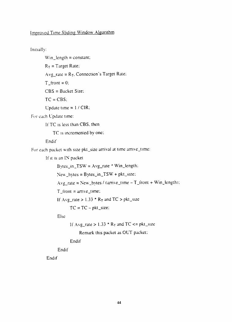
TC 1s the sument token numkr in the token buckèt; CBS is the token bucket's s i x ;
T-iront is the ttme of rhç Iast püçket arrivai; Aw-rate is the rate estirnrired upon each
priiket arriul.
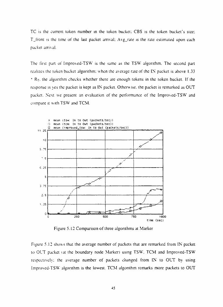
The hrst pi in o i I m p r o d - T S W 1s the w n e as the TSW dgorirhrn. The second pcirt
rc;ilizcs the tuksn b u c h algorithm: when the m m g e rate of the IN packet is above 1.33
a Rr, the dgorirhrn checks whsther therè cire cnough toksns in the tokcn buckst. I f the
rtxponsc is y the packri is kept as I h : packet. Otheru Ise. rhe packet is remarkcd as OUT
packet. SN DY prescrit an evaluation of the performance of the Improwd-TSW and
cornparc i t u ith TSW and TCM.
Figure 5-12 Cornparison of ihree algonthrns iir Marker
Fisure 5.12 shuu s that the average number of packers that are remrked from [N packet
ro OLT packet i i i t the boundary node Marker) using TSW. TCM and Improved-TSW
r<ispciti~~r.l~.: the average nurnbcr of packets chsngsd frorn IN to OLT by using
Improwd-TSW ;ilgorithm is the lowrst. TCM algonthrn rernarks more pxkrts to OUT
packers thm TSW and Irnprowxî-TSW. Thus. TCM dgorithm has the worst trliffic
pcrformlinw. Slorc 1.V packrts arc iillorwd to enter the AF sertice-capable nctupork by
usinp Iniprored-TSW rilporithm: this means that more IN plickcts are prorcctcd by using
I mpru 1 cd-TS W ~lgori t hm rrithrr than TCXI or TSW.
Figurc ? . 1 jho~vs rhat w t h Impro~ed-TSW cilgorithm ive ger rhc k s r trlitfic performance.
lx.. the Litnouni o i FTP trtiffic reccived by the rrcciwrs is the highesr. Srlrcting an
dppropriatc rnxking dgorirhm is ver. important ro .G ~~~~~~~~~capable nrtworks. e-g..
our ~irnul~itions. shou rhat trliffîc performlincc irnproves signiiiciintly if we use TSW
~ilgoriihm ~ > r Irnpru~ed-TSW tilporithm rcither thm use TCM cilgorirhm: if vie use
Inipru\d-TS\iW dmrithm rlithcr than TSW algorithm. wr set k t t e r triiffic performance
in iiur h F ~criicc-~;ipliblc nctnork with high hurst and sevcré consesrion 31 the
hoirlcncck. In the iolloriing sections. only TSW rnarking idgorithm ts used at the
ht~~ind;ir> nodcs of the AF service nr.twork to meter and remrirk plickets since we c m get
a good 1r3t'tic prrhrrnrincr for TCP trrtific in uur srmulations by using ihis algorithm and
the siniuI;itions udl run (aster than using TCM 2nd Irnprovrd-TSW cilgot-ithms (Tokcn
h i h ~ i ~ ai-c. in\ol~eci in TCM and Improied-TSW. ivhich is irnplrimcntrd by inismpts in
OPZET 2nd ii I I I prolong the simul~ition rime).
5.4 Bandwidth Allocation in AF Service-Capable Network
I n ioc1;i) '.; ksi- t . t l r t nstworks. 1 1 1 customr'rs cornpetr for the same biindwidth: therr 1s
no 2u;ir;inic.c. bit iii';tornérs ger rhc ;irnount i)r'h;indu idrh the' need. cg. . custumer m q
riwd 2 \ l h p b ~ r I idco u hile rinother iuslomcr netxis o n l y 64 Khps for audio. C s q an
.-IF scr\ iic-capahle netiiurk. Lrr arc cible to prc\ ide different amounts of' bandwidth to
drffcri'nt ciisrorncrs. In thrs section. Lie study the issues related to brindwidth
;i I luccit iuniprovisro n ( to custornen) in .AF service-capable net works.
Difkrcnt profiles are assigncd to differrnt cusromers at the boundriry node of an AF
icrvise-cripiihlr net ir ork. Each pro t? le sontains the triiffic rate that the ISP (Intemet
S c r ~ ~ c c Prowier) agrerd to proude to the sorresponding customer. In the simulations
i'hc ncr~ io rh .ir;hiicc.rure s h o w ln Figure 4.1 i s usrd in the sument simulstions. Trarfic is
l;cnt t-roni thc clients to the ssrvers. Client 1. Client 1. Client 7, Client 4. and Client 5 are
J I I FTP itlenis. Scrwr 1. S c n w 2 . Scrwr 3. Scrvcr 4. and Server 5 are al1 FTP servers.
Tr;iti'ii 1.; \cnt Iron-i Client r to Serwr I i 1<=i<=j). FTP traffic uses TCP ris rt trrinsport
protocol; a11 the FTP clients h a w the sams configuration. Thrrefore. al1 the FTP clients
gcncrritc thc same Amount of traitk. H o w v e r . Client 1. Client 2. Client 3. and Client 4
ccncrsts h F TCP traffic: this means that these clients have profiles at the boundary node - 5larkc.r. Packet5 o i AF TCP traffic are markrd as IS as long as packet's rate does not
t . \ i ~ c J rhe suhscribcd rate. Client 5 genrrcitrs best-effort TCP traffic; thrre is no profile
for this traifii ;id al1 the p a c k s are markrd 2s OUT at the Marker. Since traffic is sent
trom ilicnts to .;eners. thme are only acknowlrdgrmrnts sent from servers to clients. The
iiic uf thcsr. ~ichnoukdgerncnts is very small io cause any songcrtion in the links from
rhc w n c r s 10 the clients. Thus. we consider only Dropper (see Figure 4.1) since it is the
~ L C L ' S ~ no& IO the bottleneck link (rom the clients to the jervers. RIO cilgorithm is used
h\ Dropper: TSW rnarking algorithm is used by Marker to mrtcr and mark al1 the .AF
K P trliii'icj ;igainst differsnt profiles for difierent customers. To run our simulations we
ncçd ici ivntigurc all sirnu1;itiun piinmeters. Some piirameters have the same values as
ihsir p w r s in the simulations presrnted in Section 5.1. Therefore. only parameters thnt
h ; i~c ciiftl.rt.nt i.lilut.s rire listed belo~v.
F..ich I-TP ciicnt generritcs triiific itr a rate squd to 5OKbps at the application layer. The
h o t ~ l m x k Iink in our AF service-capable netuwk has a ciipacit y of 15OKbps only.
TS\V ;ilwrlthm 15 uscd b) rhr: boundiiry node Marker of the AF service-capable network.
Eii~h c u m m c r is a s s i p d a target rÿtr in hislhsr profile Irt the Marker: if the packet's
. i \ c r~ ipc r:iic 1s dmt L. the ia r~e t raie. the packsr is rnarked as OLT packet.
r ~ r g ~ i R.iic h r ETP Client 1: 20000bps
T.irgc.i R.irc for FTP Client 1: 4OOOObps
Tx-gct Riitc. for FTP Client 3: 10000bps
1-i1rgc.t Ratc Lx FTP Client 1: 5OOOObps
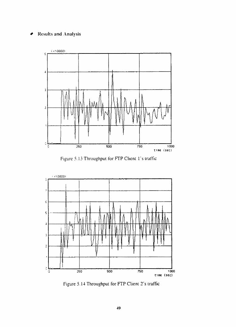
Kesults and Analysis
Figure 5.13 Throughput for FTP Client 1 ' s traific
500 750 tirne (sec)
Figure 5.14 Throughput for FTP Client 7's traffic
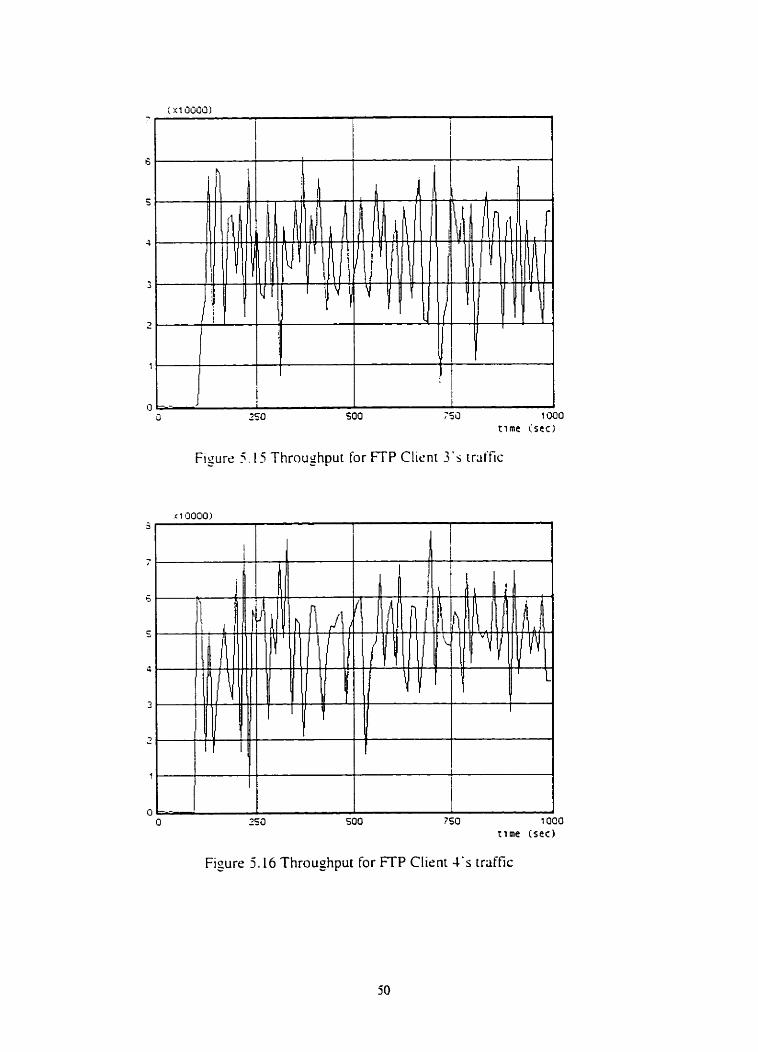
Figure 5 . 1 5 Throughput for FTP Clirni 3 ' 5 trliffic
750 1000 cime (sec3
Figure 5.16 Throughput for FTP Client 4's irliffic
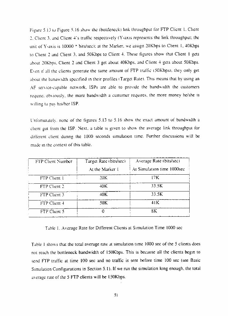
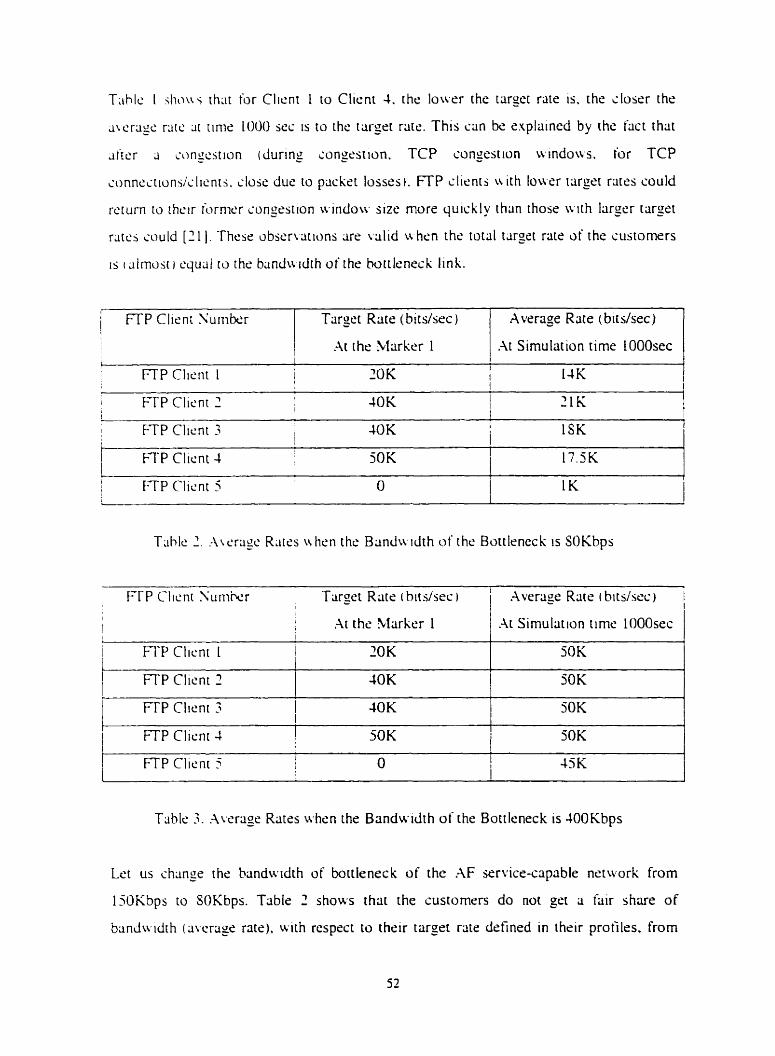
T~rhlti I s h o w th^ for Clicnt 1 to Clicnt 4. the l o w r the targct rate is, the iloser the
J \ C T ~ ~ C ralc 31 rime 1000 1s to the trirgrt rate. This ciin bc. snplained by the f x t that
d i c r J ionytstion (during congcsiion. TCP congestion uindous. for TCP
conn~itioni/iIicnt~. close duc to packet losses). mP slirnts uith lowcr target rates could
rcturn io rhmr iornir'r s o n p t i o n windou- size more quickly than thoss wth larser target
rtltt.5 a u l d [7 1 1 . Thesi: iibscrvririiins cire vrilid 1s h m the total target rate of the sustomers
is i ciimost i.qu;il ro the banduid~h of the bottlsneck link.
(
j FTP Client Surnbsr
FTP Clicnt 1 ! 20 K 1 14K , 1
Tiirget Rate (birs/src)
.At the Marker 1
I E-TP Clicnt 2 1 4OK 1 2 1 K
l 1
1 FTP Clicnt 3 40 K I 1 1 1SK
A vcrage Rate (bit dsec)
.At Simulation time lOOOsec
1 FTP Clicnt 4 50K i 17.5K
T h l s 2 . - \ \cri ic R;itss u h m the Bmdwdth of thc Bottleneck is SOKbps
I T P Clicnr S u n i k r Tiirget Rats (bitdsec I 1
4 , .Ai the Marker 1 l
i 1
FTP Client 1 1 ZOK 1
Table -3. .Average Rates when the Brindwidth of the Bottleneck is 400Kbps
Average Rate i t?its/sec)
.At Simulation timr' LOOOsec
5OK
1 FTP Clicnt 2
Let us change the handwidth of bottieneck of the AF service-capable nrtwork from
150Kbps to SOKbps. Table 2 shows rhat the custornen do not get a fair share of
bandur idth (avcrclge rate). with respect to thrir targrr rate dsfined in their profiles. from
IOK SOK
FTP CIrent 3 1 10K 1
SOK
I I T P Client 4 l i
50K i SOK
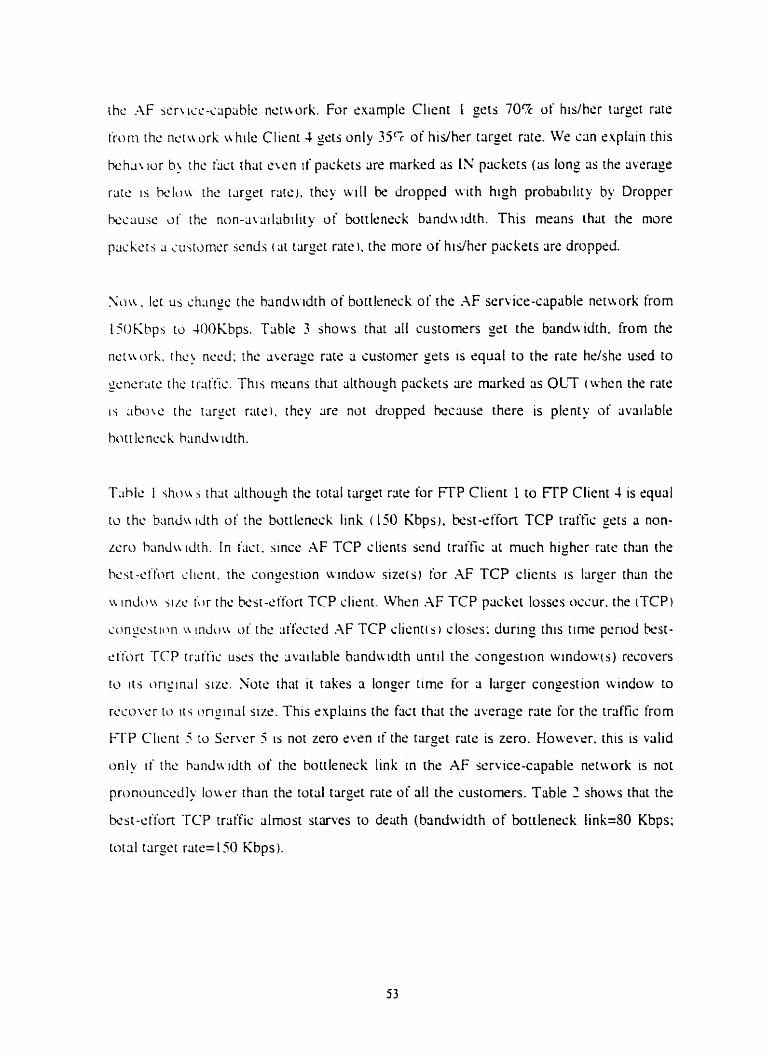
rhc .-IF wrwc-ccipciblc nctiwrk. For enample Client I gets 70% of hislhcr tcirget rate
trorti thc nctuork uhile Client 4 sets only 3 5 5 of hidher trirget rate. ive c m explain this
k h a \ ior h! rhe facl that cwn if paskcts are rnrirked as IN packers (as long 3s the average
rate 1s k l o u rhc i q r t rcitcr. they uill be dropped w t h high probability by Dropper
k c ~ i u s e o i the non-iit;iil;ibtlity o i bottleneck bandwdth. This rnrans ihat the more
packcts J cujtcimsr *ends ( a i rarget rare). the more of hidhcr pcickets are droppcd.
N w . Irir us chiinse the hrindwidth of bottlrneçk of the hF service-capable network from
1iOKhps tci 40OKbps. Table 3 shows that 311 çustomers grt the banduitth. from the
ncriwrk. ihc! nccd: thc awrage rate â cusmmcr sets 1s rqual to the rate hrlshe used to
pcncr~itc rhc tr:it'fic. This mctlns ihat although pacckcts tire markçd as OLT i whcn the rate
is ; l h w ~ ' the targct ratcl. ihey are not droppcd becciuse there is plcnry of available
bott lcncck h;indwdth.
T h l c 1 .;ho\{ i that although ihti rotal targst rate for FTP Client 1 to FTP Client 1 ts cqual
w thc h ; m h idth of the battlmxk link i 1% Kbps). &sr-effort TCP traffic = ws a non-
Lcro hmdu d t h . In t'iist. since AF TCP clients send traffic ar rnuch higher rate than the
hcst-ei'iort dienr. thc congestion windi>w sizéis for AF TCP clicnts is Itirgrr than thc
t i indou ji/.c t;)r the tesr-etfort TCP client. When .AF TCP packet losscs uccur. the (TCP)
it~rigc~tion ~i i n h u o i thc ~ i i k m d AF TCP clicnti s i closes: during this timr period k s t -
t: t'ibrt -PCP trliiiis uscs thc ;ivriilabls banduidth unt i l the congestion windowis) recovers
tu i t i origin;il sizr.. Yotc rhat it tÿkrs a. longer tirnr for a larger congestion window to
rccowr to i r i original sizs. This explains the fiict that the ;iverage rate for the traffiç from
FTP Clicnr S io Scrvçr 5 is not zero s w n i f the target rats is zero. Howevrr. this is valid
only i f the h;inda-idih of the bottlenrçk link in the AF scrvice-capable netuork is no[
pronounwdly louw than the rottll targrt riite of al1 the sustomers. Table 2 shows that the
bt .~t- t . i f~rt TCP trrtffic alrnost starves to derith (brinduidth of bottleneck link=SO Kbps;
total target rate= 150 Kbps).
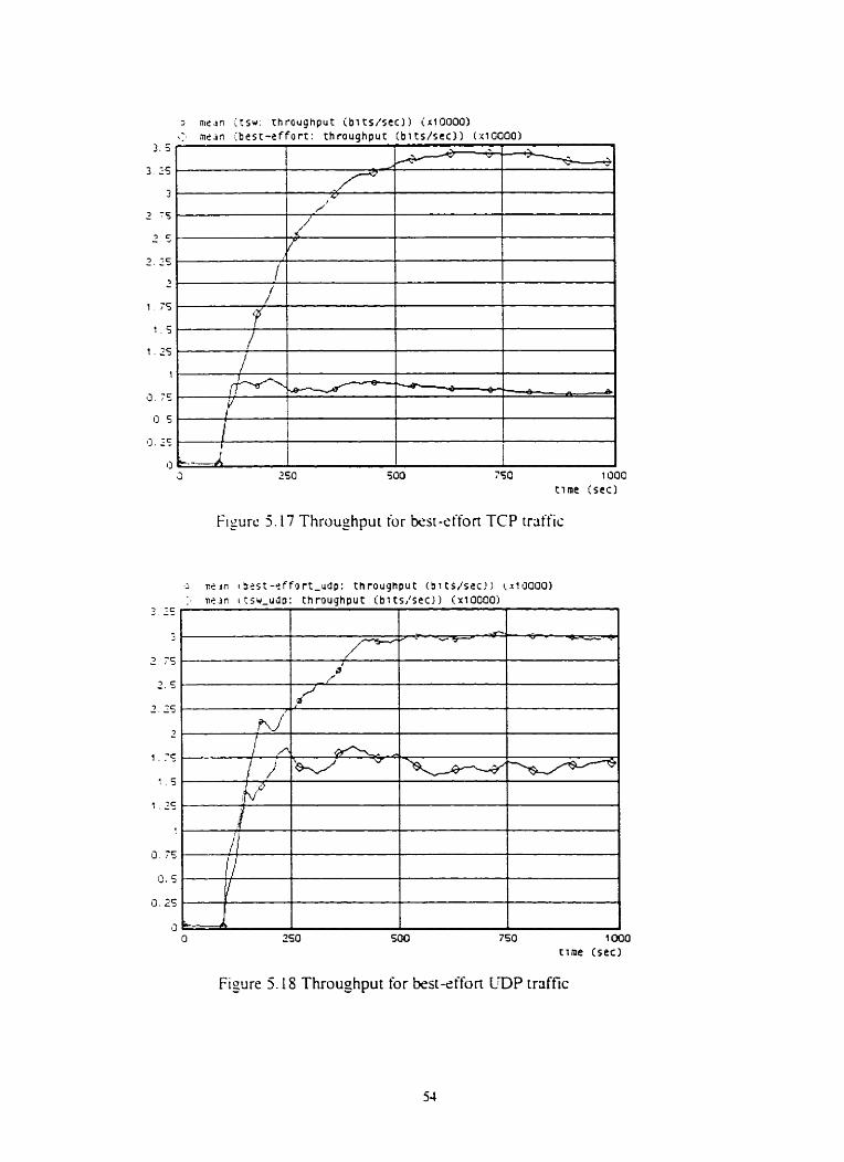
F igurc 5.17 Throughpur for &sr-effort TCP trciffiç
F i y r e 5.18 Throughput for best-effort LDP rraffic
Sou ihar u s h o u * h o w bat-effort TCP traffic is treated by the AF serr ice-capable
nctttorh, Ict US srucly ho\\ kst-effort trriffic is treated by rhe bçst-effort nctuork ( i t is the
same 2s Our AF service-capable network; however. the t q c t rate for al1 customers
(Clicnt I to Clicnt 5 ) is squal to O. Note that the bandu idth of the bottleneck link i s cqud
to 150 Khps). Figurr 5.17 shows the throushput o t best-effort TCP trriffic in the .AF
icr\i~e-ciip;ihlc nrrtwxk cusing TSW and rhe &sr-effort netwrk. The throu_ohput of
k a t - s i h n TCP in the bcst-effort netwrk is above 33Kbps whilc it 1s about SKbps in the
;\F 5c.n lie-aipiible nrtuork. In the kst-effort nctuork. all TCP customers are treated the
i,irnc. \t 3) md in civerage they gsc a hir share o f the bottleneck biindwdth (about 30
Khps m c c i u s have 5 clicnts and ;i botrlcnrck banduidth of 150 Kbps). Houcver. in the
-IF w - w c c~piihlr nctuork. rrciffic g m r x r d bu Client I to Clicnt 1 1s protected against
~ h c k t - e f fo r t TCP trafîïc: whrn congestion oscurs. kst-cifon traifiç is dropped first.
I n ihis px l i~ r r t ph . we want to ~ i n a l y e the impact of AF TCP traffic o w r best-eifon CDP
iraific in rhc AF service-capable nctwork. Nwv. Client 5 is an E-mail client and Servrr 5
is J n c-mail wver : E-mail traffic. that uses UDP as a transport prorocol. 1s gencratrd by
Clicni s .ind x n t to Scrwr 5. The configuration of the othsr clients and servrrs remain
unihangcd. The Ernaii Client generiires the rame anount of trsffic 3s the onginal FTP
i l i ~ n t . I.c.. I SOO nir.ssages/hour and the Jwrlige rmail sizt is 11500 bytes. Figurr 5.1 S
s h o w rhc rhroughput for kst-effort CDP traffic in the M iervicr-capable neruork
iusirig T S W and the bsst-effort network: the throughput of ksi-effon L D P in the k s t -
sifun n t w o r l , 1s around 3OK: it 1s around 17.5 Kbps rn the AF service-capablc network.
Thc throughpiit o i the test-effort LmP traific i s smallcr in AF service-capable nrtaork.
but nui 3.i jrnrillcr as rhs kst-effort TCP traffic (sr<: Figure 5-17). This is because the
ks i -d fon CDP cl i~nr ce-mail client) senerates traific at the snme ratc regardless of
pac'krlt 10ssr.s v. hile the best-effort TCP client (FTP client) backs off whrn pmket losses
OCCUf .
B;tsrtd on the above aniilysis. we can state that ISPs u e able to provide the bandwidth the
sustonicrs requirs hy using AF service network when the total tupt rate of the customrrs
is ( rilmust q u a i to the bmdwidth of the bottlçnsck link; kst-effon TCP traffic could get
non-mu kindir idth when the bondwdrh O < the bottlcnçck link in the AF scr~ice-iapdble
nctiiork is not pronouncedly louer than rhr total r 3 r p rate of al/ the sustomers and hest-
d o r t CDP traific c m grt more banduidth ir hen sompeting .\F TCP irafric in the AF
jcr\ I C C - C ~ P ; L ~ ~ C ' nctu ork.
5.5 TCP Round Trip Time in AF Service-Capable Network
Round Tnp Time ( R n ) is the masured rime intrrvlil k t u e r n the tims to send a piickrt
and the tinic to receive the corresponding iicknow ledgrnrnt. In surrcnt kst-effort
nc.i\wrhs. TCP pcrl'ormancr is sensitive to s connecrion's round tnp tirne iRTT). The
1;irgt.r rhc R T T irum the source to the Jesiinaiion. the more tinic needcd ro rccowr ~ n e r 3
packct in rhis traffic is lost. That's becciusé TCP's congestion control dgonthm forces
TCP wuries tc, back off t r hcnwer it detrcts iliiit a pxkc t is lost: uhcn 3 TCP sourcr
rtxciws ;in ~ihnuivledgrnent from the destination. i t incrcases its congcstion windoir
s y n . Houcwr. 11' the RTT of ii TCP connccrion is Iargrr. i t tr I I I take longer rime for i h r
TCP wuric ic, gei acknowledgments and thiis it wll take longer timr: tor [he TCP source
tu rccowr to 11s onizinal - congestion u inc io~ sizt.. Thus. a TCP conntxtion w t h shoncr
R T T L U I I tiikc more brindwx.ith in the nctiwrk sincc it i r d I recovcr to its o n y u 1
congcstion ir indoir bizr faster. This is not fur for connections w t h longer round tnp tirne
in ludu' ' 5 nctnurk.
In rhis section irc aim to anal>ze the impact o i RTT un the bandu idih iilloccition in the
.-IF ~ ~ . r \ i i ~ - c i i p s b l e nstworl. [n our simulations. ive set different RTT iduçs to diffcrent
TCP cunncctions and ihen we rneasure the ;ichisved throughput of the diffrrent TCP
ionncctron in the .4F service-capable nçtwork.
Configurations
Traffic 1s sent from clients to the servers. In the current srmulritions, ail the clients rire
FTP clients anci dl the servers are FTP ssrvers. Trrtffic is s e n t from Client 1 ro the Server i
i I c=i<=j ). Ali FTP traffic use TCP as transpon protoc01 and al1 the FTP clients have
thc jcimc confi-uration (ser Section 5.4). Thus. al1 the FTP clients genente the same
Limounc o t traific. W r rissign difi'rent link delays to different TCP connections. Link
&la<. here jpcciiics the propagation delau ivhish will bc incurred bu priskrts sent over the
I i n k First. L{C run the simulations in the kst-effort netivork: and second Ive run the samc
siniiilatic>ns in rhr AF sen icr-clipable nrtwxk. Sote thiit in the second set of simulations
T S \ ï algonihm is usrd at the boundary nodr Marker and the tarzet rate for eash client
tTCP source) 1s rhe same. Vis assume that 211 the acknotrkdgements are sent from
sr'r\.ers to clients i\.ithout losses.
To riin oui. simulations wr ncsd to configure 311 simulation puameters. Some paramrtrrs
h u c the jarne L . ~ I U C S ;IS their ptxrs in the simulations prcsentrd in Section 5.4. Therefore.
on\) px-amcrers rhat haie d i i fmnt values are listed k l o w .
WC .;ct dit'fcrcnt RTT values to riiiicrent TCP connections.
Fn)rti FTP Client 1 tu Marker 1 the d e h y is 5 scconds: FTP Scrver 1 to Marker 2 the
&Ili) is 10 jeconlis
From FW Clicnt 2 to Marker 1 rhe dela! 1s 5 seconds: FTP Scrver 2 to Marker 2 the
ili.13) is I O seconds
Frum FTP Clicnt -3 to Marker 1 the d s l q 1s 3 seconds: FTP Server 3 to hlarkcr 2 the
d ~ l i i ) is i j~sonds
From FTP Client 4 to Marker 1 the d r i q 1s 3 seconds; FTP Sttrver 4 to Marker 2 the
d c l q 1s 5 seconds
From FTP Client 5 to Marker 1 the dela) is 1 second: FTP Server 5 to Marker 2 rhr delay
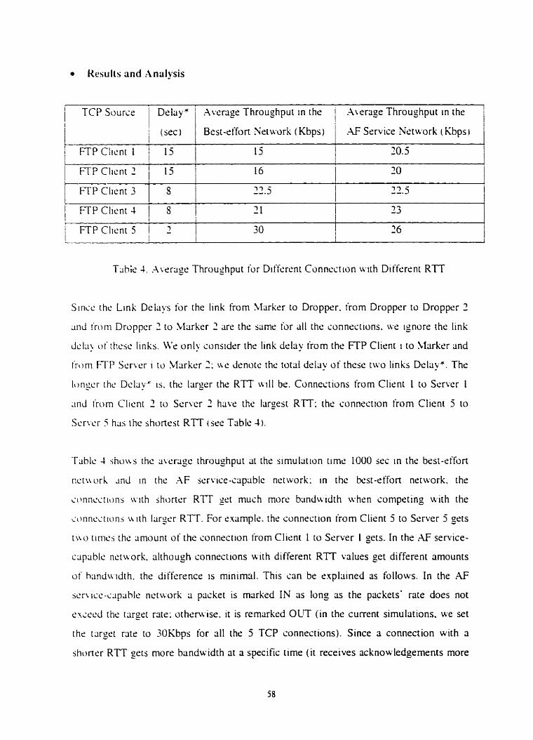
Uesulls and :inülysis
1 FTP Clicnt 2 / 15 I 16 1 20 I 1 FTP Client 3 I S I 3 3 - ---3 i 7 3 j - -. I
/ TCP Source I
FTP Client 4 1 S 2 1 1 13 I
Delayx ' .Average Throughput in the 1 A w a g e Throughput in the
Tiible 4. .-\writgc. Throughput for Diifcrent Connccrion uvith Dilferrnt RTT
i (sec) 1
Bcst-effort Nrtu.ork (Kbps)
; FTP Clicnt 1 i j 1 1
15
Sirici. th<: Link Delay ior the link from to Dropper. irom Dropper to Dropper 2
; i d irom Droppcr 2 to Miirkcr 2 arc the saine for (il1 the connections. ur ignore the link
dcl;i) of thcsc links. Ws only sonsider r h r link drlay irom the FTP Client i ro Marker and
tTom FTP S c r ~ x r i to Marker 7 ; ive cienors thc total delriy of these tivo links Delay*. The
Iorigcr rhc Dcl;iyS is. the largsr the R T T W I I bs. Connections from Clicnt 1 ro Servcr 1
~ i n d rTom Clicni 2 to Srrver 2 have the I;iro_est R I T : the connection from Client 5 to
Serwr 3 ha'; r hc shortest RTT i sse Triblc 4 1.
.G Service Nstu-ork (Kbps)
30.5
Tablc 4 shuw thc average rhroughput at the simulation tirnr 1000 sec in the best-cifort
nci\ri)rh ~ n d i n the h F service-ctipable nctwork: in the &sr-rffon nctwork. the
connsc.rions a i t h jhorrcr RTT get mush more biindwidth when cornpeting with the
ionnciiiunj V. i th 1;ir~t.r RTT. For rxample. the connrçtion from Client 5 to Srrver 5 sets
i
t u o t iriics thc amount of the sonnecilon (rom Clicni 1 to Server 1 gets. In the .AF service-
cqciblc nctworlt. although conneciions H ith different RTT values get different amounts
of h~indu idth. the differencs 1s minimal. This can be rxplained as follows. In the AF
sen icc-cspahle netivork a packet is marked IN as long as the packets' rate does not
t..rrer.d rhr icirget rare: othrrv..ise. it is remcirkrd OLT (in the current simulations. we set
the tcirget rate to 30Kbps for al1 the 5 TCP connections). Since a connection with n
shoner RTT sers more b m d w idrh at a specific time ( i t receives acknou.ledgements more
i;i.;ti.r,. it 15 more likely that it will exceed the targer rate [han conncctlons tt i ~ h longer
RTT.;. li this happens. rhr paçkets (o f this sonnecrion) are rnarked OLT and are first
dropped b ) Droppcr i t hm i o n p t i o n occurs: in this ciise. the TCP source ( w t h shonsr
RTT) b a ~ k i oif ireduccs iis scnding rate) and ihus rhe connections a i t h brgrr RTT haie
the oppununit ' to gct mors ~ivliilable bandu idth to use.
i3~isc.d ori the analysis above. w r san srair rhür the impact of R I T on thc bandwdth
allosciiion in iht: ;\F service-capable netuork is minimal compxed to the ccisc of the k s t -
t'fïim ncttvork.
5.6 Support of Expedited Forwarding Service in AF Service-Capable
Network
ln rhc currcnt sirnulmons. w r usrd a pnority queuing mode1 to provide ION delliy and
Iw jittcr h r EF service trailic in t he AF senice-capable network. Packris of EF service
arc put inro 3 high prionty queue in the interior nodes of the XF service-capable network
u hilc .)thcr packers <.IF service packets and best-eifon service packets) are put into
mtirhcr loir pnurity queue. The pückets of EF service are fowsrded before other packets.
hlthough AF seri ice packsts and kst-effor? packets are ail in the low priority queue. hF
Thc y ~ i l « i the simul;itions describcd bdow is to rinalyze whethcr EF service rraific sîn
h supponed i n thc .AF service-capable nctwork and to cvrtluatc the impact of EF senice
trriffis on .AF service and best-effort trriftis.
The nctv.ork nhitecture s h o w in the Figure 4.1 1s used. Clicnt 1 is a Vidco Coniercnce
Clicnt ancf S e r w 1 1s rt L'ideo Conkrence Sc.r\.ice. Clicnt 2 , Client 3. and Clicnt 4 are
FTP cl~c'nts; Scrwr 2. Server 3. and Server J arc FTP scrwrs. Client 5 1s an E-mail Client
anci Scrwr 5 1s rin E-mail Servcr. Trriific is sent tiom Client i to Servcrr i ( l<=i<=S). The
u i c o conierence trLiific gener~icd by Client 1 represcnts the EF service traffic. This
rr~itfic uscs CDP protocol and requlrcs low Jela? and low jitter. FTP traffic uscs TCP
protocd 3 r d rsprcsents the AF scrvisc traffic t i hile the E-mail rrilffic uscs LDP protocol
2nd rcprcsents the &sr-effort trdfic. Therr are tu.0 profiles î t the boundary node Marker:
ont is r),r h F irril'fic and the other one is for EF trliific. TSW algorithm is implcrncnied at
K t r l c r mcrer 2nd remiirk the EF and h F scruct. traffis iiginst the two pruliles.
Pnurir) quculng niodcl 2nd RIO dgonthm cire impiementecf in the intcrior node Dropper.
N'c dsiiinlr thai dl the iickno\vlrdgemrlnts are scnr frorn serwrs to clients without losses.
Clicnt I gcncrcitcs ?OOKbps video conference trriific. It is the main pan of the total traffic
in th!'; rietuork.
Cmicrcnss R~ite: -4s conkrences/driy
Awrîge Con ference Durrition: 30 minutes
Frlimt. Rlitt.: 30 frarnedsecond
Frrirnc S m : 1250 bytes
FI-P Clitxt Attnbutes
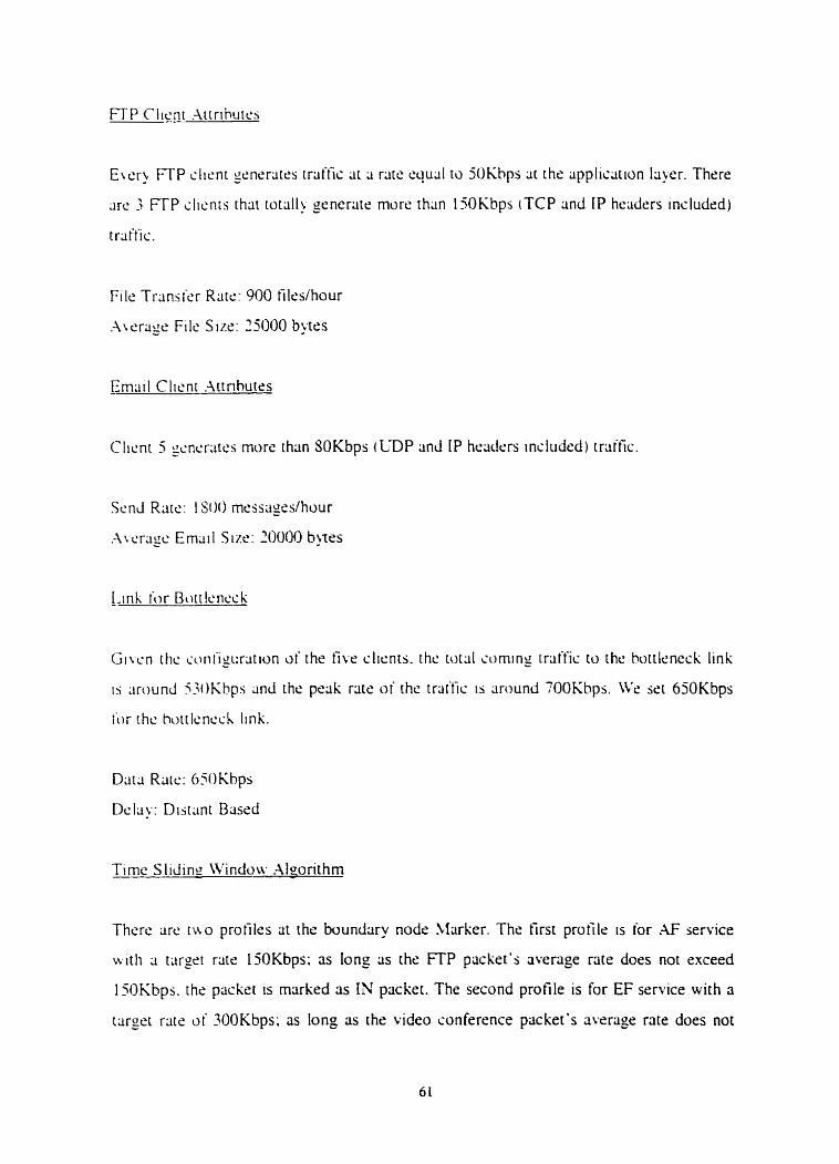
Clicnl 5 gr.ncr;iics more than SOKbps (CDP and IP heiiders included) trliffic.
Timc S licfinn W i n d o w .Mgonthm
Thcre arc trio profiles at the boundary nods Marker. The rirst profile is for .4F service
N i th targrt rats I 5OKbps: as long 3s the FTP packet's average rate docs not exceed
15OKbps. the packet 1s marked 3s IN packet. The second profile is for EF service wirh a
t q e t rate of 100Kbps; as long as the video conference packet's average rate does not
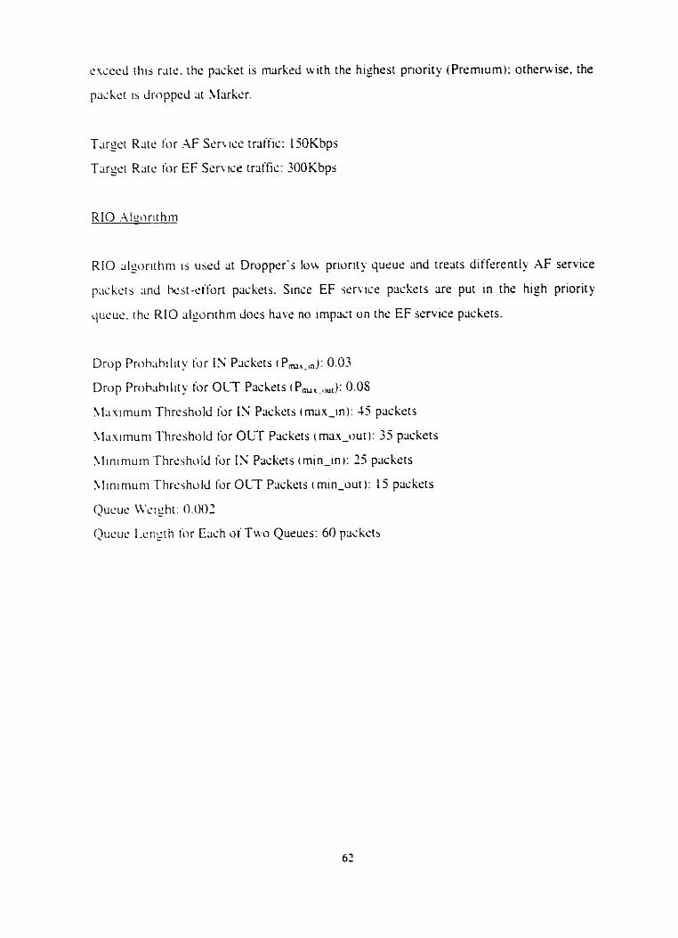
cxsecd rliis rlirr.. rhc packrt 1s markrd with the highest pnority (Prrmium); orhrrwise. the
packcr is drupped at klrirkcr.
RIO .AIcorithm
RIO iilwrit - tini is uscd dt Dropprr's low priorii y queue and rrerirs differently AF service
p;ickcrs iind ka-e t for t packris. Sinse EF s c r u c r packers are put in the high priority
L ~ U C U C . thc RIO slgonrhrn docs ha\.r no impact on the EF service packets.
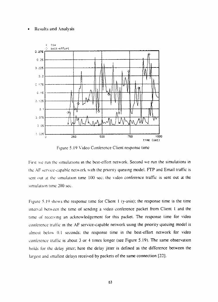
Figure 5 . 1 9 I'idco Conirrcncr Client responsc time
First i v c ruri thc ';imulrttions in the kst-st'fort nettvork. Second wt' run the simulrttions in
rhc ;\F 5 c . n ice-~iipiihlc nctnork u ~ t h rhs pnority quruino_ model. F-TP and Email traffiç is
Figurc 5l11 show the response timc for Client 1 (y-axis); the response time is the time
irirervtil hciur.cn ihe time of sendinp a video cunference packet from Client 1 and the
timc o i rrcciiing an cicknowlcdgernent for this packet. The response time for video
conkrc ncc trdtiic in the AF service-capable nrtworli ustng the pnorit y queuing model is
:ilniost k l o u 0.1 seconds: the response timr in the best-effort network for video
mnic.rcncr rratiiç is about 3 or 4 tirnes longer (see Figure 5.19). The same observation
holh for the dchy jitrer; hrre the drlay jitter is defined as the difference between the
larrt.st and jmallest delrtys received by packets of the same connection [ 1 2 ] .
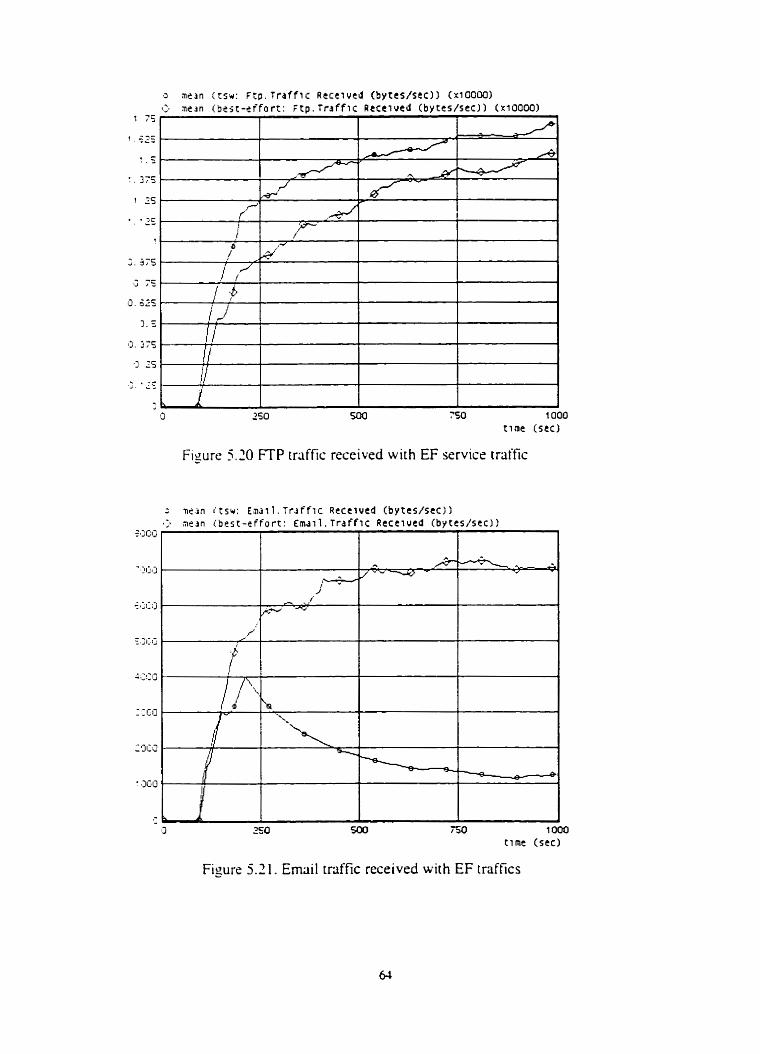
Figure 5.20 FTP trriffic received wich EF service traffic
2 ne i n i tsu: Endl 1 . Traf f i c Rece ivcd ( b y t c s / s e ~ I
750 1 O00 t i rne (sec)
Figure 5.2 1. Ernail traffic received wiih EF traffîcs
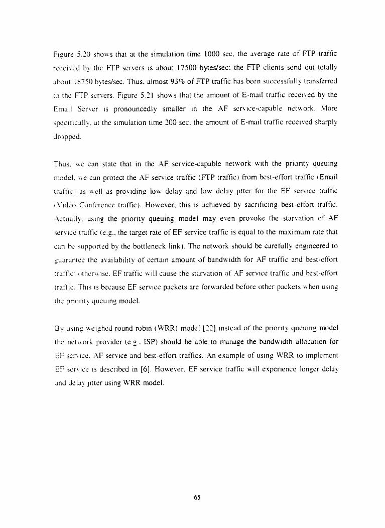
Figure 5 . 3 show that at the simulation time LOO0 sec. the riveragr. ratr of F-TP traitlc
rccci~cd by the FTP scrvers is about 17500 byiedsec: the FTP clients send out toially
;ihour lS750 hj t rdsec. Thus. ~ilrnost 93%- of FTP traffic has k e n successfull~ trilnsferred
ro the FTP scrvers. Figure 5.21 s h o w that the amount of E-mail triiffic receiwd bu the
Eiiiciil S m e r is pronouncedly smaller in the AF seruce-cripabls netuork. More
spesiiisally. ar the simulation tirne 200 sec. the amount O ? E-mail traffic recsiwd shlirply
droppd.
Thus. u c u n sute thnt in the AF service-capable network with the prionty quruing
modsl. ue c m proisct the .AF service rraffic (FTP trriffic) irom k t - s i f o n traffic (Etnail
rrailic i as ~ c l l ris prouding lou dclliy and low d e l q jitter for rhe EF ser~,ice trciffic
i L ' idc~ Conicrcncc traific). Howevcr. this is achicvcd by sacriking best-cthn trafic.
.-\ctu;illy. using the priority queuing model may e w n provoks the starvation of AF
ii.r\.icc. tr;~itic kg. the targrt ratr of EF service traffiç is equal to the maximum rats that
<;in hc. iupponrd by the boitleneck link). The network should be crirefully enginsrrd to
gii;imnrrr. the avriilabilitv of certain amount of banduidth for AF trtiffic and best-cffon
traftii: d i c r u 1st.. EF trtiit'ic \ i . i l l cause the starvation of .4F st'rvlct' trriific anci kst-cfhrt
irsi ' i ï i . This 15 kcause EF servici: priskets rire ioru.cirdrd hcforc othcr packrts \ \hm using
riic prirlrit) qucuing rnociel.
B ' usin: ueighed round robin (WRR) rnodel [XI instçiid of the pnonty queuins mode1
ihc nctrwrk provider (cg.. ISP) should be able to rnanri_oe rhr biindwidth allocation for
EF .;c;i.iic. AF ser\.ice and kst-effort traffics. .An example of using M'RR to irnplcrnent
EF ic r \ ICC is describcd in [ 6 ] . However. EF service traffic uill rxpericnce longer delriy
; i n J Je!+ jittrr using WRR model.
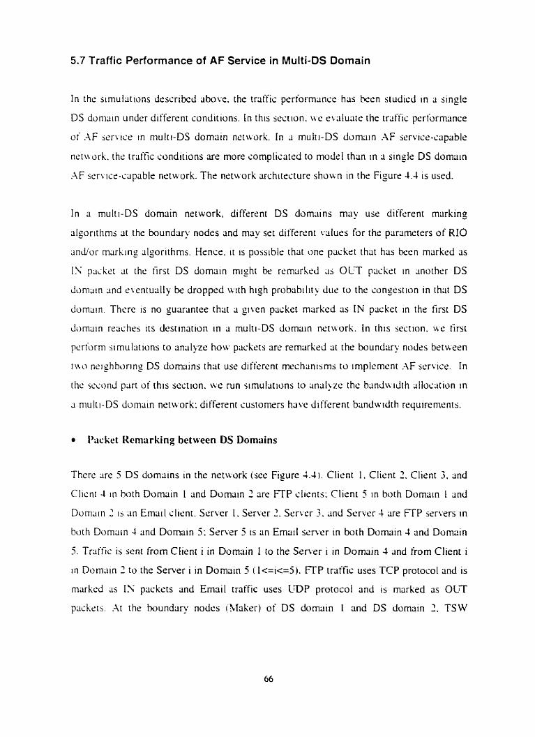
5.7 Traffic Performance of AF Service in Multi-DS Domain
I n rhc simulations descrikd above. the traffic performance hlis k e n siudicd in ri single
DS dc>mciin under difkrent conditions. In this section. ire etciluaie the trcilfic performance
o i ;\F wrticr in mulri-DS domiiin nctu.i>rk. In 3 rnulti-DS domain AF scrvi~~-capilble
net\\ orh. the traffic conditions are more complisated to model than in a single DS domiiin
.-\F sen icc-capable network. The nctwork architecture shoumn in the Fisure 4.4 is used.
I n a multi-DS domain network. different DS domains ma' use different mxking
îIporithms cit the bounduy nodts and may set differrnt values for the paramerers of RIO
~ indor rncirking slporithms. Hencr. it is possible rhat anc packet ihat hiis k e n markcd as
IS packet at rhc first DS dorniiin mlght be rcmarhrli c i i OLT packet in mother DS
c l m u i n anci cwntually br: dropped with high probabilit> duc to the consestion in thnt DS
domam. Thers is no guariintrr thar a =ilen packet markcd as Ilu' packet in the first DS
Jorntiin rsaches its destination in a multi-DS dornain nctwrk. In this section. we tirst
pcrform simulations to ancllgze how packets are remarkcd rit the bundtiry nodes berusen
i w nrighboring DS domains thiit use differcnt rnechlinisms to implcment hF service. In
rhc sr.c.ond part of this section. s e run simulations to iin;il>zc the bcindwdth allocrition in
a niulti-DS d o m m nctwork: differrnt customers have diffcrrnt bandwidth requiremcnts.
Packet Rcmarking between DS Domains
Thcrc arc 5 DS domains in rhe network (sec Figure 4.4 . Client 1. Client 2. Client 3. 2nd
Clicnt 4 in both Domriin 1 and Domain 2 rire FTP clients: Client 5 in both Domain L and
Domrtin 2 15 Lin Emarl client. Server 1. Server 2. Serwr 3. Lind Ssrver 4 are FTP serwrs in
both Domain 1 and Dornriin 5: Ssrver 5 is an Emrtil servèr in both Domriin 3 and Domttin
5. Trriffic is sent from Client i in Dornriin 1 to the Serwr i in Domriin 4 and from Client i
in Diiimîin 2 to the Server i in Domain 5 i l<=i<=j) . F-TP traffic uses TCP protocol and is
msrked as IS packers and Emnil rraffic uses LDP protocol and is rnrirked as OLT
p;icksts. .At the boundtiry nodcs i-iIaker) of DS domriin 1 and DS domain 2 . TSW
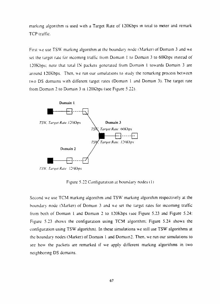
marking idgorithm is used uiih a Tareet Rate of l2OKbps in total to meter and rernark
TCP trrtffic.
wt the rciroei r;itc. îbr incornmg trliftic tiorn Domain 1 1 0 D a m m 3 to 6OKbps inrtsad of
120Kbps: note t h s t total IN packers generated h m Duniriin 1 lowards Dornain 3 are
riround 120Kbps. Thsn. ur: run our iimuliirions ro cl) the rcmiirking procrss k tween
ruo DS doniciins u i t h diifercnt tcirgsr rates (Domain 1 and Domain 3). The tu= =et rate
from Domain 2 to Domciin 3 is 1lOKbps (see Figure 5 . 2 2 ) .
Figure 5-22 Cunfigurcition tir bounrliiry nodes ( L i
Second ive use TC51 rnarking algonthm and TS W msrking iilporithm resprçtively ai the
houndsr). nods (Marker) of Domain 3 and LW set the iargct rates for incoming traffic
from h t h of Dornain I and Domiiin 2 to 12OKbps i ser Figure 5.13 and Figure 5.24:
Figure 5.73 shows the configuration using TCM dgonthm: Figure 5.24 shows the
contigur;ition using TSW algorirhm). In these simulations ur still use TSW algorithms at
the boundary nodrs (Marker) of Dornain L and DomliinZ. Thrn. we run O u r simulations to
sec how the packris are remlirkrd if w r apply different marking algorithms in two
ncighhring DS demains.
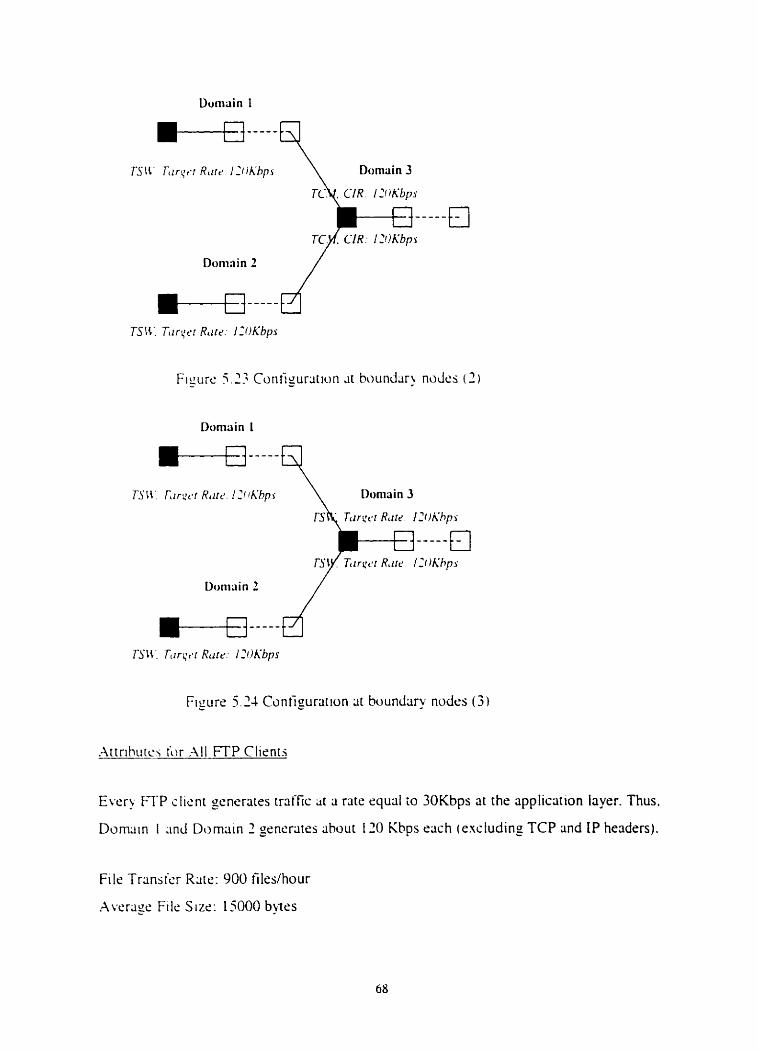
Figure 5 24 Configuration rit huundap nodes ( 3 )
.Artrihiirc\ L)r .\II FTP Clients
Evcr? FTP clicnt gcnerates traffic ;ir a rate ciquril XI 30Kbps at the application iayer. Thus.
Domitin I ~ n d Domain 2 generates ahout 110 Kbps rcich iexcluding TCP and IP headers).
Filcl Transier Rate: 900 files/hour
Avcrcigc File Sus: 15000 bytes
.-\ttrihutcs for .Ml Emml Clients
Eiich Emai! clicnt ( in Doniain 1 and Domciin 2 ) gcnerrites traffic at a rate squal to SOKbps
:it the i i p p l ~ c . ~ t ~ ~ n laycr. Thus. t h m is totlilly more thm 160Kbps (including LDP and IP
h c d ~ r j 1 oi KDP trriffic to enter the Domriin 3.
TSW . ~ l c o r ~ i h m in the Mirker o i Domain 1 and Domiiin 2
f h c r c 1% 2 profile for crich o i the FTP client at ihr boundary nods 'rlarksr of Domiiin 1
;ind Domun 2. I f a pncket's raie dors not excerd the truget rate set in the profile of the
<lient gcnc.r;iting thc paçket. it is mcirkrd IN.
Bk n m i . LW bnou thar Dorniiin 1 2nd Domain 2 genrratr more than 12C)Kbps of TCP
ir;tir'ii ~ ; i i h [ou 3 r d ~ Doniain 7. Thcrciorc.. ur set the target riite for TCP rraffic at
hoiinclx! n d r a of Domciin 4 and Domiiin 5 to IZOKbps.
RIO .\lcorithm in the Dropwr of Domttin 3 --
ln r h ~ jin~uliiiions ws uscd diffrrent thresholds for M and OUT prickets for RIO
dlgoriilim ,ri di ffrrent domins: this is retilistic since each domain may have different
puliciirs tu niiina_or IN and OLT packsis.
Drop Pruhlibility iur IN Pxkets (Pm,-,.): 0.03
Drup Prohahi lir! for OLT Prickers i Pm,-,,,,): 0.08
\lii\iniuni Thrcshold for IK Packrts (min-in): 50 packets
\liiumurn Threshold for OLT Packers (mal-out): 40 packris
Mini n iuni Thresho Id for 1% P x kets (min-in 1: 30 paskets
hlini rtiurn Threshold for OLT Packrts (min-oui): 20 plickets
Qiicuc b'cight: 0.002
RIO .-ilccirirhrn in rhc Dropper of Domain 4
\ ire 5r.t 10nc.r tlirc5holds for IN and OLT paskets in this Dropper. Thus. althoujh a large
riiinihcr , i f pa ih~ t s 1s Liropped by Droppcr Domainj. still a numbcr of prickrts mighr b<:
Drop Proh;ihilii) Ior [': P;iiket~ t Pm,-,,): 0.03
Drop Proh;ihilit) for OLT Packets t Pm,-.,,,): 0.08
Mciuiriiiirn I'hrcjhold for IS Prick~tj (mrix-tn): 40 plickets
\l;i\iniiim Thrcshold for OLT Pricksts (rncix-oui): 40 packets
hlinirnuni Thrcstiold for IS Packets (min-rn 1: $0 packers
Mini tiiuni Thrcshold for OUT Packcts (min-out ): 10 packets
( ~ U C U C Wcight: 0.002
\Vc ,cc 1onr.r thrcihulds crhrin the onrs for Domain 4) for OLT packets for Dropper in
Donuin 5
Drop Prohiibiliry fur IS Packets (Pm,_,.): 0.03
Drop Piohshilii y for OLT Paccksets 0.08
\I:i.uirnurri Thrcsholc! for IN Packets (mx-in) : 40 packets
Xfrisirnum Threshold for OUT Packets (mm-out): 30 packets
Minimum Thrcshold for IN Packets (min-in!: 20 prickets
Minirriurn Threshdd for OLT Packets (min-out): 10 prickets
Qucuc Wcight: 0.002
Bascd o n the iibovc setrings the total traffic thtir çnrrrs DS Domriin 3 ir higher than
4OOKbpj. Ws set the bandutidth of botrleneck Iink in Dornain 3 ro 4OOKbps; we decidr so
[O cause' iungSst10n.
Bot~lencck Link in Domriin 4 and Dornain 5
By n o i r . uc know that Domain 1 and Domain 3 senerate about 2OOKbps of TCP 2nd
l 'DP ~ r r i i t ? ~ u c h twurds D o m a n 4 and Dumain 5 (v ia Domain 3). Wt. set the bmdwdth
ot' txirrlcncck links in Dornain 4 and Domain 5 to IOOKbps.
I n rhis multi-DS domriin nstwork ÿrchitccture. thrre lire 5 domains. TSW rnarking
algorithni h~is k e n implemrnted at the boundary nodes (Marker) o f Domain 1. Domain
1. Doniain 4 and Domnin 5 . RIO riigonthm has ken implemented in Dommiin 3, Domain
1 and Domilin 5 (Dropper). Differrnt drop thresholds in Ri0 algorithm are used in
Jifikrcni domains . In the current simul3<ions. we focus on the boundary node Marker of
the Domriin 3; the traffic from both Domain 1 (via Link 1) and Dornain 2 (via Link 2)
enter this node. There are only two profiles ot the Marker of the Domain 3: one is for the
trriffic irom Domain I and the ocher one is for traffic from Domain 2 . This means that
3lsrki.r at Domain 3 manages the aegregate trriffic generated by Dornain 1 (resp. Domnin
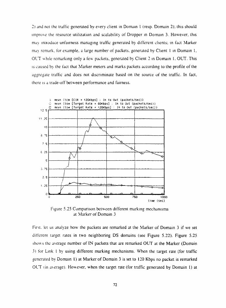
2 ) 2nd not rhr: tmific generatrd by svery client in Dornain I (resp. Domtiin 2); this should
iniprwrt ihrt rcsourcr utilizlition and scalsbility of Droppcr in Dornain 3. Hoivever. this
ma) ~niroduse unfriirness rnanaging trriffic penrratrd by difft'rçnt clients: in hst Marker
ma\ rcniiirk. for sximple. a large number of plicksts. gcnrratsd by Client 1 in Dornain 1.
OLT ~ h i k rcmarking only ri feur packrts. ~rneriited hy Client 2 in Domain 1. OLT. This
i j c;iusr.d by the tact thÿt Marker merrrs and marks packcts according to the profile of the
iiggregtc rrciffic and does not discriminate based on the source of the traific. In hct.
rhcre 1s a irade-off between performance end fairnsss.
Figurc 5.25 Cumparison betwrn djffrrenr marking meçhanisms rit Marker of Domain 3
> m e d n itcm [CIR = 1 2 0 ~ b p s ) : In to Out (packcts/sec)l .:, medn ( t s w [ T d r g e t R a t e = ~ O K ~ P S ] . l n t o 3 u t (pdck~ts/sec)I C medn (Cs* [ T d r g é t R d t e = iz0KbpsJ In CO O u t ( p d ~ k e t s , ' s t c ] )
12 s p
1 1 2 5 ,
10
Firsi. let us ;iniilyze how the pockets cire remuked at the Marker of Domain 3 if we set
Jiflcrenr t q e t rates in two neighboring DS domains (ser Figure 5.12). Figure 5.25
jhu\\s ihc ;iverage number of IN packets that are remrirked OUT at the Marker (Domain
3 '5
7 S .
3 for Link 1 by usin_o dîfferent marking rnechanisms. Whrn the target rate (for traffic
gcnsrcitsd by Domin 1) at Marker of Domain 3 is set to 110 Kbps no packrt is rernarked
OLT i in iiwrrigr). Hoivever. when the target rate (for traffic generated by Dornain I ) at
1
\.
Q.
\- J
" -'+ c 25 I
I l /
i-1 . R R e m m
250 500 750 IO00 cime (sec)
5 ,
3 ' S )
2 5
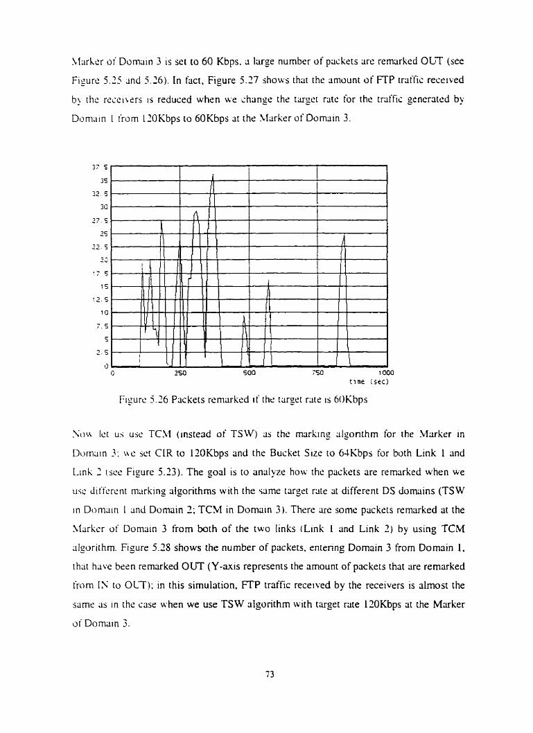
Marker of Domain 3 is set to 60 Kbps. 3 hrge number of packers are remcirked OLT (sre
Figure 5 . 3 2nd 5.26). In fact, Figure 3.27 s h o w thrit the m o u n t o f FTP traffic recrived
b ) thc rccciLers is reduced when we change the tiirget rats for the traffic gsnerated bu
Dcimiiin 1 from 1 IOKbps to 6OKbps ;it the Marker of Domain 3.
Z ~ I N Ict us use TCkl (instead of TSW) 2s the markmg dgonthrn for the Marker in
D w w n 3 : LW Sei CIR to llOKbps and the Buckrt Sizs to 6IKbps for both Link 1 and
Link 1 WC Figure 5.23) . The goal is to ancilyze how the packets are rernarked when we
use dilïr.ri.nt m;irking algorithrns with the same targct riite ar differcnt DS domains (TSW
in Domain 1 m d Domain 2; TCM in Domain 3). There are somr packets remarked ai the
1,Iarkr.r of Domriin 3 from both of the two links (Link 1 and Link 2) by using TCM
algorithm. Figure 5.28 shows the number of packets. rntenng Domain 3 from Domain 1.
rhat have bcen rernarked OUT (Y-mis represents the arnount of packets that are remarked
(rom IS to OLT); in this simulation. FTP traffic received by the receivçrs is almost the
same as in the case when we use TS W dgorithm wit h target rate 1 ZOKbps 3t the Marker
or Domain 3.
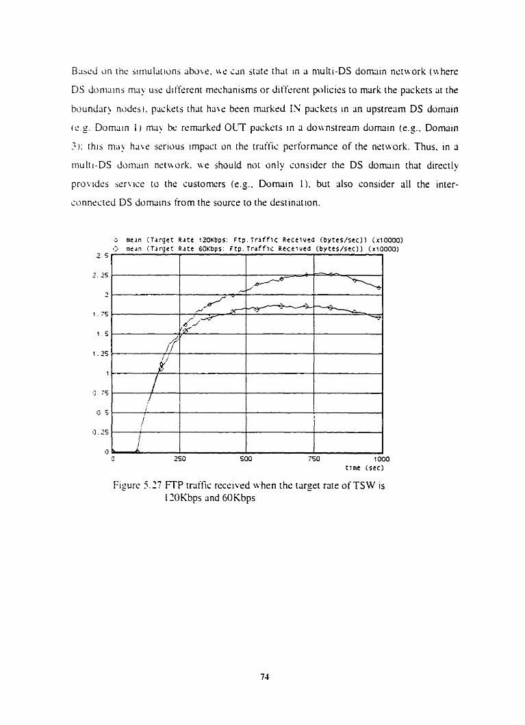
B i i d on thc jiri~ul;itions abwe. ut. i;tn jt;tts that in ;i n~ulti-DS domriin nctwork (whert:
DS doni;iins ma! use ditfsrcnt rncçhanisms or diffcrent pdicies to mark the packets iit the
buundcir> ncides). p~ckrts that h u e bsen markrd IN piickrts in ;in upstrexn DS domain
(CS. D o m m L ) ma? be rerniirkd OLT packers in (i do~~nstrerim domain (cg.. Domain
3: thia ma) h a i e serious vnpiiçt on rhe triiffic pcrlormiince of the neiwork. Thus. in 3
mulii-DS domiiin n s t w r k . ire jhould not cinly consider the DS dommiin that directly
proudcs e r i x x to the sustomers (es.. Domain 1). but also consider d l the intsr-
ionnecteci DS ciornains from the source to the destinrtt ton.
a medn C i a r g c t R ~ r t 12OKbps: ~ t p . T r d f f l c R ~ c e l u e d ( b y t t s / s ~ c ) 1 (~100001 O medn ( T d r g e t Rate 6 0 K b p s : F t p . T r d f f i c R c ï t l u t d ( b y t e ~ l s t c ) ) (~10000)
2 5'
2 . as
3 . - 1 . 7 5 .
1 s .
1 .25
.
,-d
L
1
13. 75
u S .
13.ZS
-- Y--*- -
O 250 500 450 i 000 r i m e (sec)
Figurc 5.27 FTP triiffic receivrd when rhc tareet rate of TS W is 12OKbps and 6OKbps
-
/ /
I'
- / I
dH d-
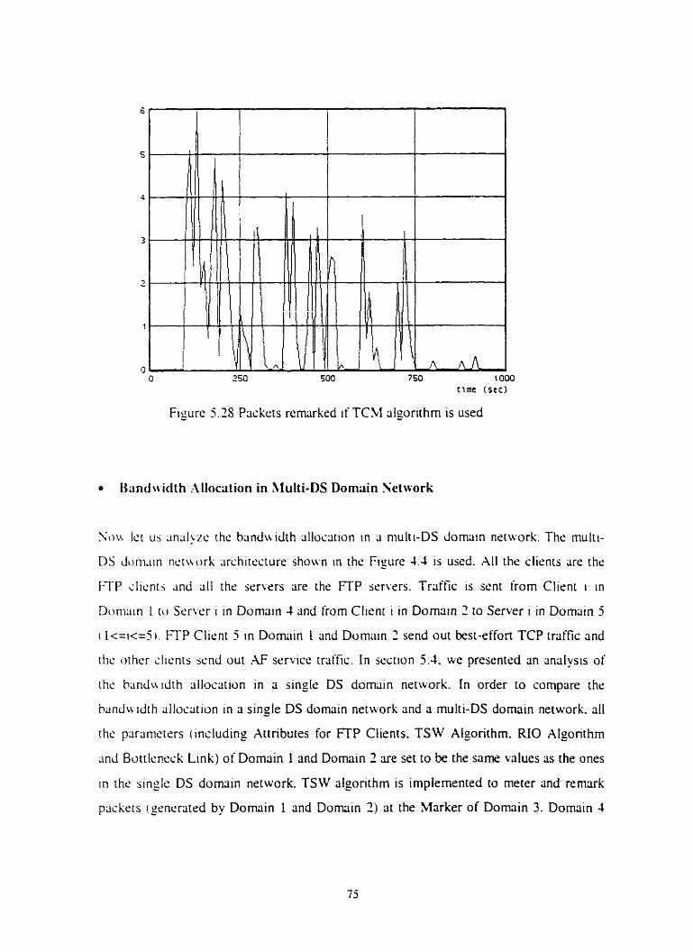
c ime (sec )
Figure 5.28 Packets remarked if TCM algorithm is used
S u Ict uj m;il!,zc th<: hiindu idth ;illocation in ii rnulti-DS clornain nstuork. The multi-
DS d o n i m nctirurk iirchitrcturr s h o w in the Figure 1.1 is used. XII the çlienrs are the
FTP iIicntj anci di thé serwrs are the ETP ssrwrs. Traffic is sent from Client 1 in
Duniriin 1 [ c i S s r ~ w i in Domriin 4 and (rom Cllent i in Domriin 2 to Server i in Domriin 5
i 1 < = ~ = 5 1 . ETP Client 5 in Domriin L and Domain 2 send out bat-effort TCP traffrc anci
itic othcr slicnrs scnd out .AJ? service tralfic. In jecrion 5.4. we presentrd an rindysis of
ihc bandiiidth alloscition in a single DS domain network. In order to compare the
handu idth allocation in a single DS domain network and a multi-DS domain network. al1
the parameters ( indudint Attributes for FTP Clients. TSW Algorithm. RIO Algonthrn
;incf Bott!c.ri.èck Link) of Domain 1 and Domain Z are set to be the same values as the ones
in the sinzle DS domain network. TSW dgonthm is implemented to meter and rernark
packers fgentmtrd by Domain 1 and Domin 2) ai the Marker of Dornain 3. Dornain 1
and Domm 5 arc. turo non-DS domains and dl the packets are treated the same in these
N O DS cicimains.
T S\V A l ~ ~ ~ r i t h r n - in the Xlrirker of Domain 3
Doiiiain 1 mJ Dcimain 2 generate about 150 Kbps tach (sec Section 5.4) e x h . LVe set ihc
r a y a rate 150Kbps for traffic coming from Dornain 1 and for traffic coming from
Dornriin c l .
Targct Riire fur E x h of Two Links: 150000bps
l'hc RIO algorithni rhrcsholds we set for ih' and OLT in Domain 3 are différent from the
corrcsponding rhrcsholds set in Domain I and Domciin': different domains may use
Ji~icrcnt piilicics to manage iN/OL;T packets.
Drup Prohahilit) fur Ii: Packsts (Pm,-,.): 0.03
Drop Proh;hilit~ for OUT Packers (Pm-,,,,,): 0.08
\i;i\irnuni Thrcshold for IN Packets (man-in): 50 ptickets
1l;t.rirnum Thrcshold for OUT Psckrts (mm-out): 40 ptickets
Hininiurn Threshold for IN Psckets (min-in): 30 packets
Minimum Thresho Id for OUT Packets (min-out): 70 prickets
Qucuc Wight : 0.007
Botrlcntxk 1-ink in Domrilin 3, Dornriin 4 and Domrtin 5
WC set the bitndwdth of rhe botrleneçk link of Domain 3 to XOKbps: note that the total
rrliffic genrr;ited by Domain I and Dornain 2 is around 300Kbps. This mems that severe
congestion c m occur. In the current simulations. we set the bandwdth of the bottleneck
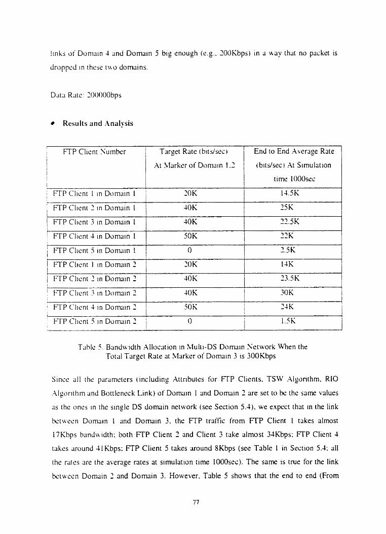
!inlis o i Duni;iin 4 2nd Domain 5 big rnough ( c g . . 2OC)Kbps) in a w y that no packrt is
Jroppcd in i h c x tua domains.
Kesiilts and .-tnrilysis
: FTP Client Sumhtir Tiirget Rate <bits/sec) End to End .Average R x e 1 1 A t LLarkeioiDiimain 1.3 i bitdsèc .At Simulation
1
/ FTP Client 2 in Domain 1 1 4OK ,
?SE[ I I
1 FTP Clicnt 3 in Donisin 1 1 4OK
I 1 I
/ FTP Clicnt 2 in Domriin 2 1 40K 1 3 3 . x
2 2 . X
1 FTP Clicnt 1 in Domain 2 1 2 0 K 14K 1 I
I i
1 FTP Clicnt 1 tn Domriin 2 1 SOK i 1
1
/ FTP Client ? i n Domain ? i 4OK
Triblc 5 . Bandwidth .\Ilocrit ion in Multi-DS Dcmriin Xetwork U'hen the Total Target Rate at Marker of Dornmn 3 1s 300Kbps
ZOK
Sincc ( i l 1 thc pitramerers (including Attributes for l T P Clients. TSW .\lconthm. - RIO
. \ l p i t h m and Bottlrneck Link) of Domain 1 and Dornain 1 are set io be the same values
3s the oncs tn the single DS domain network (see Secrion 5.4). we cxpcct thiit in the link
k t w c n Domriin 1 2nd Dornam 3, the FTP trrittic from FTP Client 1 takes riimost
17Kbps h;indwdth: both F ï P Client 2 and Client 3 rake almost 34Kbps: F ï P Client 4
tcikss around I l Abps; FTP Client 5 takes uound 8Kbps (see Table 1 in Section 5.1: a11
the rates ;ire the average rates at simulation rime 1000s~) . The same 1s tnie for the lhk
ktwccn Domain 2 and Domriin 3. However. Table 5 shows that the end ro end (From
FTP sl~cnt to F i P rcrwr) average rares for 311 the tratfic are ~ilmost the same. which
mcrins that ~ h c clienrs ( i n Dornain 1 and Domain 2 ) did not get the bandwidth t h r y iiskzd
for in Dom~iin 1 and Domiiin 2 (ses trirget rates in thrse two domains) in this multi-DS
domain nctwrk. In fast. ii client wirh high tarzct rate (a[ the source DS domain: Domain
1 or Domain 2 ) is more likrly to have its piickets droppsd by Dropper of Domain 3. This
i d n hct cxpisind b > the fact that Dropprr 1s reseiving more packers (thlit sxcreds the
blinduxith of the bottleneck link of Domain 3) from this client thm other clients.
Obviously. this causes unhirness in rhe bandwidth allocation in multi-DS domain
nctwrks: clients gr nerat in3 high data rare are discriminated againsr. Note that the
bandividrh of the bottleneck in Domain 3 is set to lOOKbps while the total target rate
i frorn Link 1 2nd Link 21 ln >Iiirker of Domain 3 1s 3OOKbps.
Fruin thc a n a l y s or bandwidth allocation in Section 5.4 (sec Table 2). LW conçluded thrir
iusiomcrs do not pet J fur share o i bandwidth (average rate). w t h respect CO their target
rate dcfined in their profiles. from an (sin$e-DS) AF srrvice-capable network i f the
biindwidth of rht. b~mlsneck link 1s muçh loir er rhm the ciggrepte traffic seneratrd by
thc sustomers. Thus. it is more cornplex to satis- thc bandu-idth rcquests (defineci in the
profiles :Ir thri sourie DS domain) of custornen in a multi-DS domain ncwork since the
hot~lcneib links ot'diifercnr domains ma)- have diifcrent bandu tdth içiipacity) n hich ma);
bc. diffcrcnt lruni rhe total aggegats traifiç gsnrratrd by the custorners.
Noir. Ici us run the same simulations but after chmging the target rate of Link 1 and Link
3 to 100 Kbps ( in rhr previous simulations Link I and Link? have a target rate of 150
Kbps) ~ h i s h is equd to the bandwidth of the bottlcneck link of Domin 3. Tiiblr 6 shows
~ h ~ t the end to end awragr rate for evsr) clirnt-srrwr 1s far less than the tcirget rats
d i . f ind in the profils (s imilx to the results in Table 5). In faa. in thrse simulations. the
xgregiltç traffic that enter (from Domain 1 and Domriin 2 ) Domain 3 is xound 300Kbps
whilc rhc total trirget rate at Marker of Domain 3 is equal to 7ûûKbps. Thus. 3 large
numhtx o l pxket s are rsmarked OLT iit the Xfarker. Since :Marker (of Domriin 3) keeps
only the sute of Iiggregate traffic from Domain 1 (resp. Dornain 2). it could remark more
packcts OLT from Client i and a fewer paçkets from Client j (l<=i.j<=j); this means that
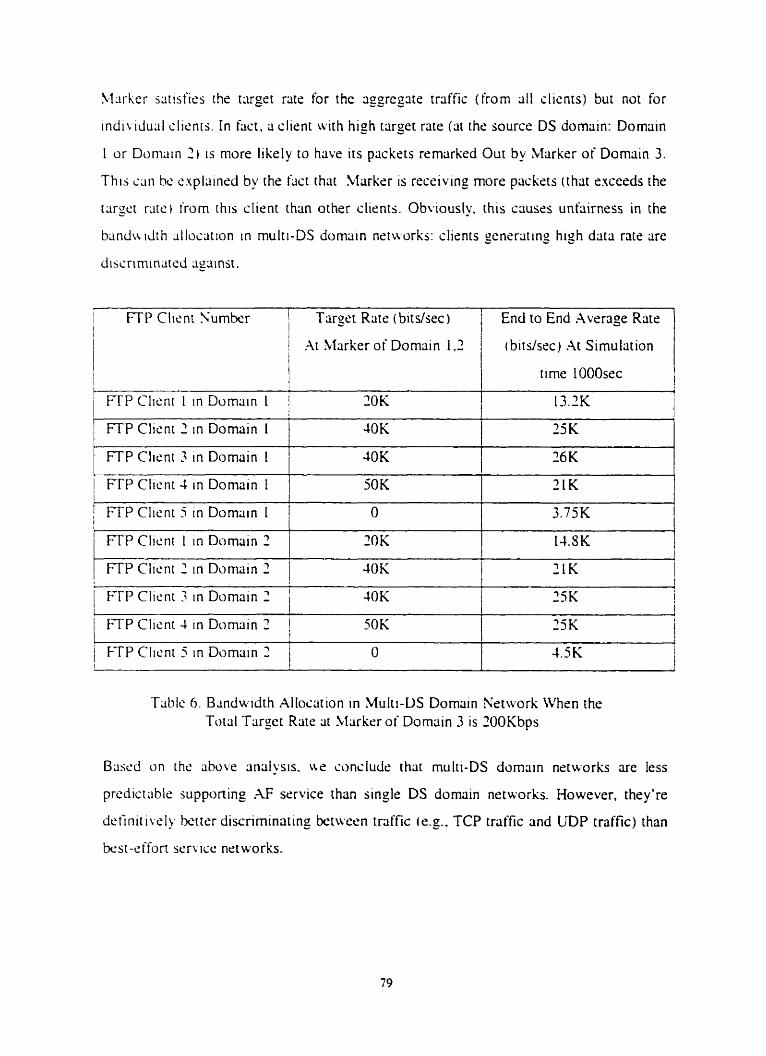
5, l~rker utisfics the txget rate for the aggregxe traffic (frorn dl clicnts) but not for
indn iducil clienrs. In hçt . a client u i t h high target rate (at rhr source DS domain: Domain
1 or Donlain 2 ) is more likely to have iis packets remnrked Out by Marker of Domain 3.
This can hc. cxplsincd by the hct rhar Marker is receiving more packets (that excerds the
tarpet r~irc) irom this client than other clients. Obviously. this causes unhirness in the
bandu idth ~lloc;iiion in rnulti-DS dommiin nstuorks: clients generritins high data rate are
d~ssrimin~tsd ligriinsr.
I FTP Client Sumbcr 1 Targst Ritte ( bits/sec) 1 1 At Marker of Domrtin 1 ,3 1 l
End to End Average Rare
c'bitdsec) .At Sirnutrition
time lOOOsec
FTP Clicnr 1 in Dornain 1 j 30K I I 1 3 . X
/ FTP Client 5 in Domun 1 1
FTP Client 2 in Domriin 1 4OK 35K
36K
21K
FTP Client 3 in Dornain 1 ' 40K
1 FTP Clicnt 2 in Domain 2 1 !
1 I
+
1 FTP Clicnt 4 rn Domrtin I
, / FTP Clicnr 1 in Domain 2 1 ZOK
i
I FTP Client 3 in Domain 2 1 4OK 1 25K i
50K
J
14.SK
Table 6. Bmdwidth .4lloctition in .Multi-LIS Dornain Xetwork \C'hm the Toicil Target Rate iit .LI arker of Domciin 3 is lOOKbps
FTP Clicnt 4 in Dornain 2 1 !
50K
i FTP Clicnt 5 in Domriin 2 1 O
Bascd un the ahove rinrilysis. u e sondude thrit multt-DS domriin networks are less
prcdictiiblr supponing .rF service than single DS dornain networks. However, they're
definitivcly txtter discriminating between tnffic kg. . TCP trÿlfic and IiDP traffic) than
h s t -èffon service net works.
25K
4 . K ,
5.8 Summary
In this chliptr'r. ue presrntrd the simulations we performed to euluate the performance
oi .-\F sc.rwri-srip;ibIs netu,orks supponing dilkrent types of traffic. Bascd on these
51 mul;it ii>ns. u s art2 ~ O I I i ibk to ansrver the questions/issurs wr idsnt itird in chapter 1 :
i 1 1 B y using .\F service-capable network. the TCP traffic is protectrd (against LDP
iratfic j ; in f a i t the smount of TCP traffic successfully transicmed increases for both
long- l i ~ c d F ï P traific and short-lived WWW traffic.
i 2 > B y using TS W algorithm as a rnarking algorithm. ive are able to handle high burst
r r;il'tïc. k t ter than usiny TCM algorithm.
3 . n nilirking ~lyonthm. callcd Improved-TS W algonthm. has k e n defincd. Our
sirnuliit~oni j hou td rhnr Improvrd-TSW periorms bcttcr than TSW and TChl
d p i t hms.
( 4 ) .An .W st'r~icc-capable nr t~wrl i 1s able to provide different arnounts of biindwidth to
d i t k e n t cuitomers: this mcms that such a nstwork is able to support vidro users.
sudio uïcrs. etc. by provisioning the required bandwidth for r x h user.
( 5 ) By uiing .AF icrwe-c<ipabls nstworks. the impact o t RTT on the btindwidth
~ l l i~c i i t on in rhc nctwork 1s considcrabiy rcducrd (cornpiireci whén using bat-effort
jc'r\.ic'e nctu orks).
( h 1 EF service traific cun be supponed in AF service nrtworks: in hc t EF service traffic
cers low dclay and IOW drlay jitter that meet its requirements. Note that AF service b
trctffic is protrmd in rhe presençe of EF service traffic: however. best-effort service
trtiitic su fiers.
i 7 i Ii 1s rwre somplicated to evaluats the traffic pcrfomance in multi-DS domain
nctn urks t hm in single-DS d o m i n nctworks. However. Our simulations showed that
i 1 ) AF service-capable networks (single-DS) perform better than M service-capable
nctu.iirks imulti-DS): ( 2 ) it is not obvious to predict the traffic performance in AF
sen-ice-iiipablr nstworks (multi-DS); and (3) Al? service-capable networks (multi-
DS) perionn better than roday's best-effort service networks.
Chapter 6 Conclusions and Future Works
In rhis chapter. we conçludc our work and propose idus for turure w r k .
6.1 Conclusions
I n current Intcmrt. nctnork providers tend to provide dl thsir sustomers the scime type of
pcrforrnsncr i 1.e.. kst-cl ion service). In kst-effort s r r w r . 311 the piickets are treaird
rhc wme n a ' (it th<: routers. es.. Loice packris. udco packers and data packrts: u hcn
iiingcsLion ocsurs. packrts are discxdrd without taking into accuunt thrir type and thus
thcir rcquirrmcnts. Panicularly. \ \ h m congestion ocçurs TCP trriffic suffers in the
prtxnce of LrDP traffic. In fact, the TCP end-to-end congestion control mrçh;inisms
forcc the TCP sources to back off whenever congestion is dctrcted in the neiwork: this
d l w r 5 CDP rrriific to rdie more brtndwidth in the network and to s t m e these ut.11-
k h a \ t i f TCP sources. Funhrrrnore. the k s t - d o n mode1 is also inadequate for
~pplic;itions such as red tirne audio and vidro that rrquire cxpliçit bandwdth and dday
cu,ir;tntccs.
To iolvc the above issues. IETF hris proposed Differentiiited Services fr;imt.work:
piirricularly. two services have k e n definsd: Assured Funvarding (AF) seruce ;ind
Expdited Forwiirding (EF) service. In this thesis. we rvaluated the trafic performance of
ditfcrcnt types of triiffic in AF service-capable nrtworks. In the foilowing we presrnt our
nuin iindings:
1 By using .W service-capable nrtwork, the TCP traffic is protected (against LDP
traftic): in fact the amount of TCP traffic successfully tninsfemed increases for both
long-livrd FTP traffic and short-lived WWW traffic.
1. Bu using TSUr algonthm as a marking algorithm. we are able to hmdle high burst
rraific better thm using TCM algorithm.
.-\ neu markin? algorithm. callsd Improved-TSW algorithm. has bern defined. Our
simultit ions showed ~hat Improved-TSW pcrforms betrrr [han TSW and T'CM
dgurirhms.
.An .4F w r \ . i c - a b nrtwork is able to providc Jiifcrcnt ~ m o u n r s of bandu idth to
diffcrent iustomrrs: t h i j melins rhai S U C ~ a nrtulirk 1s able w suppon vidso usm.
sudio users. etc. by provisionmg the requlred b;indn idth for u c h user.
BI, usinc C .-\F ser~~tce-c;ipdAr nérworks. the impact of RTT on the bandwidth
dliocation in the nerwork is considsriibly reduced (compareci uhen usin: best-effort
scrvrcé netuwks).
EF ser~.icr trciffic c m be supponrd in AF service nètwrks; in fact EF service irriffic
rets low dclay and lo~r J e l q litter that m e t its requirsments. Sots rhlit Al? service
rraific ts prurcctcd in the presence of EF service iraifiç: h o w w r . bes..st-effort service
trliific suifers.
I t is more complictirrd to tviilucite the traffic performance in multi-DS domain
nçt~rorks t han in single-DS domain nctworks. Houever. our iirnulat ions shoued that
i 1 ) r\F srrvice-capable net~rorks (single-DS) perforrn bctter than AF service-capable
nciaorks imulti-DS): ( 7 ) i t is n a obvious to predict the traffic perfornirince in .AF
sc.r\ict.-capcible nctuorks r mulii-DS ): anci i 3 1 Aï sen icr-capable networks r rnulti-
DS i pcrtorrn kt ter r h m todriy 's kst-effort sen ice netuarks.
6.2 Future Works
Po~;sihle tuturè rcscarih. related to this thesis. a n bè summririted as follo~rs:
Thc bandu idth assurance discussed in this thesis is uni-directional; that is. only the
sc ndrr' s uutgoing traffic is guiiranteed a t hroughput prescribed in the profile.
Funhcrrnore. in a11 our simulations w r assumed that the acknowlrdgements from the
rcccivers are never losr. However. we have no _ouarantrr that the receivers have an
;idquate pro fi le necessary to mark returning acknowledgements (ACK). If the ACK
p x k e t s are mlirked out-or-profile and lost with high probability. the scndrr's throughput
is i o rcd ro hc. iimitcd by the losses cwn ii' the scndrr has 3 large t i i r p rate in hisihsr
protilr. [ 2 2 / . Ewn if sn .ACK pcickrt is miirked IS (it the boundary node of the first DS
duniain (Iissummg mulii-DS environmenti. wr have no guaranrec thnt this packets can
rc;lih ~ h e dcsrinmon; in hct. intermediate DS Jumciins oiay remcirk i t OUT and. thus.
drop i r i f thrrs is nor cnough brindwdth in this DS domciin. An interesting future work. is
to run our sirnulrit ions to e w luatdaniil yse the pertormlince of bi-directional traffic.
In dl thc rimularions we performd. the rratfii: modcls we have used. such as FTP.
iL'WW anci Email. ;ire al1 the modcls providrd by OPSET. OPNET traffic models
dssurnc p x k t ;ind sonncction amvals arc i l I l Poisson processes for annlytic simplicity.
Ho~+-e~, t . r . numhclr or .;tudies have s h o ~ n that for both loc;il-rireci and wide-arc2 network
rrciitic. thc disrribution of packer inter-;trri\al clexly Jiffers irom Poisson [?-II. Poisson
m - i v d processes cire quite liniitcd in their burstiness. especicilly whrn multiplened to 3
high Jcgrcc. Soms srudies. howevcr. show thrit %ide-area traffic is much burstier than
Poisson rnodels prrdiit [24]. This gçater burstinrss has implications for man. aspects of
iongrsrion conirol and tr-iffic performance. Rrcent w r k s have shown that packtt amval
proccsst.s apptiiir ro tki btrtirr modrllcd b> using Pareto processes (?-Il. An interesting
iùturc work 1s to run ciur simulations uith new traffic modsls with Pareto processes to
j l i b~ t i i~ t c rhe Poisson processes: rhis tuII iillou to e~aluate/analyse the performance of
r hcse "realist ic" traific modrls in AF service-capable nrtworks.

REFERENCES
[ I S i c w n i . W. Ris hwd. 'TCPIIP ~Iluzrrated: the protoiols". 1994. Addison Wesley.
p p - N I - p p j l l .
[1] .-lnind>,;i Basu ~ n d Zhsng Wang. " .A Comparative Study of Schemes for
Dii'icrcnricited S m ICSS". Bell labs Tcchnical Report. .k~gust 1998.
[ 3 j D. B l x k . S. Bllisk. hl. Carlson. E. Dwies. Z. Wang. and W. Weiss. " An archkcture
fur Drfkrentiritcd S ~ w x s " . IETF RFC 3 7 5 . Decemkr 1998.
[-II K. Sichols. V. Jacobaon. and L. Zhring. '- A Two-bit Differentiated Services
Arc hitccture for the Inrsmct". ftp://ftp.re. Ibl._oo~./piipsrs/dsarch.pdf, Novembrr 1997.
[ 5 1 IETF, http://u-LC w.irtf.org.
161 L i n J;iit)bson. Kar hlwn Yichols and Kedarncith Podun. "An Expedired Forwarding
Pt iB", IETF RFC 2 3 S . June 1999.
[TI Juha tfeinrtncn. F r d Baker, Ndter Weiss and John Wroclawski, " .\ssured
Forurirding PHB Group", IETF RFC 2597, lune 1999.
[SI P. Ferguson and Ci. Huston. "Qu;ility of Service: Delivering QoS on the Internet and
in Corpomtr Kct\vorks". Wiley. 1998. 320 pp.
[ I O ] K. Xichols. S. Blake, F. Baker and D. Black. "Definition of the Differentiated
Sen,ices Field tDS Fieid) in the IPv4 and EPv6 Herrders". RFC 2374, Decemkr
199s.
[ l 11 Y. Bernct. r.1 al. " .A Frcirnerrork for Diffsrentiared Services". IETF Intsrnet Drait
<llr;itt-ict i-ciiiiserv-frame\t.ork-O2.txt>. Februuy 1999.
[ 121 Y. Berncr. D. Durham anci F. Reishrneyrr. " Rrquirements of Diff-Ssrv Boundxy
Rourcrs". IETF Internet Drali <driift-krnrt-diffedge-0 1 .txt>. November 1998.
( 1 3 . \ lukul Goyal. Piidmini Misrti and R q Jlain. " Effect of Nurnber of' Drop precrdence
in .Assurrd Forwirding". 1 ETF Intemet Drak <draft-go yal-dpstdy-di ffserv-0 1 . t m .
l l u r i h 1999.
[ l i ] D. Clark and W. Fang. " Explicit .-\llocation of Best Effon Delivery Service".
IEEEi.\C\I Tram. o n Settvorking. vol. 6. no. 4. pp. 362-373. August 199s.
[ 16 1 D. Cliirk m d I. ~i'roclÿwski. " .An ~ p p r o x h to Service .Allocation in the Intemet".
IETF Inrcrnct Drdt ccfraft-ciark-difi-svc-riiloc-OO.tnt>, JuIy 1997.
[ 171 Dukc Hong and Tatsuya Suda. " Congestion Control and Prevention in ATM
Sçtwrks". IEEE Network. Vol. 5. No. 1. pplO - pp 16. Iu ly 1991.
[ l S ] S . F1+ mi Y. Jliiobson. " Random Exly Drtcction Gatrways for Congestion
.-\uiidlince". IEEELACM Transactions on Networking. Vol. 1. No. 1. pp397 - 113.
.August 1993.
(191 T. Bemrrs-Lee. R. Fielding. and H. Frystyk. "Hyprnext Transfer Protoçol --
HTTPII.0". IETF RFC 1915, May 1996.
[20] .Andrai S. Tancnbaum. "Cornputer Nerworks". 3 rd Ed. 1996. Prrnticc: HaII. Inc..
ppJ5S - 459.
[ 2 1 ] J Ihinez and K. Nichols. " Pre l iminxy Simulation Evaluation o i an .AssureLi
Scri i d . [ETF [ntemttt Drrift <drafr-ibanez-dtffserv-;1ssur~'d-e~;11-00.t~~>. August
199s.
2 2 Keshw. Srinixmn. "An engineering approach to cornputer networking: .\TM
ntmwrks . th<: internet. and the telephone nrtwork". 1997. Addison Wesley Longman.
lns.. pp219 - 220. pp236 - 137.
[li] Hbugon Kim. Wiil E. Lrliind. and S u s m E. Thomson. " Evduation of Biinduxith
.-\ssuriincc Service using RED for Intemet Service Differentiation". I u l y L99S.
t'rp://fcp.~Ilcore.com/pub/world/hkimlassured.ps.Z.
[141 h n Pd.~jon and Sdly Floyd. "Wide-Ares Traffic: The Failure of Poisson
.\.fdiilin$"' IEEE1.ACM Tr;tns;ictions on Networking. 3 3 i. pp. 226-224. Junc 1995.