Embed Size (px)
Citation preview

GEIntelligent Platforms
WellheadRTUSolutions


Wellhead RTU Solutions
Table of Contents
Brochures…………….Page 3
Presentations………..Page 21
Datasheets…………...Page 35
Parts List………………….Page 175


Brochures


PAC8000 RTU
GEIntelligent Platforms

pac8000 rtu
PAC8000 Remote Terminal Unit (RTU) thrives in
the desert heat of the Arabian Peninsula and the
arcticcoldofSiberianoilfields—deliveringquality,
reliability and safety for your success.
With increasing pressure to improve opera-
tional performance, meet environmental
specifications and overcome rising energy
costs, oil and gas operations must efficiently
and securely monitor and control entire
processes across local and remote loca-
tions. You need a partner that understands
your business and can deliver the expertise
and capabilities to drive results.
The PAC8000 RTU solution from GE Intelligent
Platforms enables you to easily monitor,
diagnose and maintain your utility assets—
even in the most hazardous environments.
Access to timely and accurate mission-critical
information from fixed
A ruggedized, reliable RTU
assets such as oil and gas wells, compressor
stations, pipelines, fluid storage tanks and
utility meters, can eliminate critical gaps
in your oil and gas operations, resulting in
higher productivity and long-term growth.
Benefits
Designedbyexperiencedprocessengi-
neers, PAC8000 RTU is simple to use and
delivers significant cost savings and value:
• Toughenvironmentalspecificationsfrom
–40 to +70 degrees Celsius continuous
operation;10yearsofserviceinClassG3
corrosive environments
• Inherentreliability-redundantCPU,
power supplies, communications
• Easymaintainability-hotreplacement
and automatic configuration
• Integratedintrinsicsafety(optional)
• IntegrateoptionallywithSafetyNet–TUV
certifiedtoSIL2
• Scalabilityfrom8to1024I/O
• Extensivediagnosticsforremote
health monitoring
• Minimumcostfieldmounting
• Lowcostofownership

In the unlikely event of failure, PAC8000 RTU maintains
your operations with robust redundancy capabilities
and flexible communications options.
www.ge-ip.com/pac8000rtu
Controller redundancy Redundant controllers can be used for
critical applications whereby the redundant
controller pair operates in parallel, checking
status multiple times through the process-
ing loop and enabling the backup controller
to continuously monitor the health of the
Master controller. It ensures a rapid and
bumpless transfer to the standby controller.
Network redundancyPAC8000 RTU has two high-speed Ethernet
ports to provide communication security.
Each port can be connected to an indepen-
dent LAN, which is continuously monitored
for its integrity. If the primary port detects
a network failure, traffic is immediately
switched to the other LAN to maintain full
communication.
Communication protocols• DNP3overEthernet
• ModbusTCPoverEthernet
• ModbusRTUSerial
Each controller has two serial ports that
can be configured as a Modbus Master
to control and obtain information from
ModbusSlaves.Theserialportscanalsobe
configuredasaModbusSlave,accepting
write commands from Modbus Master
devices and providing information on its
data registers.
Executable programsThe control programs are held in nonvolatile
memory and can be restored automatically
after power cycling of the controller. A new
control program can be downloaded to a
controller while the existing program is still
operating. When the download is complete,
the controller will automatically switch to the
new control program—without interruption
to the operation of the plant.
Failsafe and automatic cold startThe RTU supports fault tolerant com-
municationstotheControlRoomSCADA;
however, in the unlikely event that the
communications are lost, the RTU can
either continue to operate autonomously
or adopt a user-defined safe state. If the RTU
continues to operate, data will be logged for
transmission once communications have
been restored. In the event of power loss,
it will perform a cold restart, which restores
the program(s) and assumes a predefined
status. Controllers can also be configured
to perform a “warm start” if RTU power is
temporarily lost during a brownout.
Ensuring continuous operations
Firmware updates
In keeping with its ability to maintain operations on a continuous basis, a redundant PAC8000 RTU can receive a firmware upgrade.

Powerful features
HART® passthrough
PAC8000 RTU can pass smart HART in-
formation from field devices to a distant
PC workstation, allowing you to readily
interface to asset management software
applications to remotely manage the HART
information contained in your HART-based
field instruments.
Hazardous area operation
PAC8000 RTU is designed to operate in Class I,
Division2andZone2hazardousareas
andcancontrolI/Omodulesthathavefield
wiring extending into the more hazardous
Division1,Zone1andZone0areas.
With PAC8000 RTU, you can meet demanding oil
and gas applications while gaining a sustainable
competitive advantage.
I/Omodules
I/Omodulestransfersignalstoandfrom
field instruments. Input modules receive
signals from transmitters and sensors and
convert them into a digital form for presen-
tation to the controller, while output modules
receive commands from the controller and
transfer them to actuators.
There are a wide range of modules, includ-
ing types for low-level instrumentation,
AC mains and intrinsically safe signals.
I/Omodulestypicallyhave4,8or16field
channels. A small footprint with a packing
densityof3-6mmperchannelallowsfor
installations where space is a premium.
Field terminals
Field terminals provide the interface between
theI/Omodulesandthefieldwiring,includ-
ing fusing and loop-disconnect as options.
AmechanicalkeyingsystempreventsanI/O
module from being inadvertently connected
to the wrong type of field terminal.
Mounting onto the module carrier, one
toeachI/Omodule,fieldterminalsare
clampedfirmlybytheI/Omoduletoform
an electrical and mechanical assembly of
high integrity and may be replaced in ser-
vice without removing carriers or disturbing
the operation of other modules.
PAC8000 RTU IN yoUR sysTEmPAC8000 RTU is designed for use in the harshest environments, operating over a temperature range of -40ºC to +70ºC, and it is resistant to 30g shock, 5g vibration and G3 corrosive environments.
Each PAC8000 RTU controller node can address up to 64 I/o modules, which, depending upon the number of channels per module, can provide up to 1024 I/o points at a single node! A node can consist of a mixture of analog and discrete modules—providing maxi-mum flexibility to system designers.

Systempowersupplies
Systempowersuppliesareavailableforthe
nodetoconvertlocalACorDCsuppliesto
power the node and provide field power for
I/Omodules.Powersuppliescanbeoption-
ally redundant and any failures are flagged.
GE’s innovative bussed field power scheme
for distributing field power avoids complex
wiring at the field terminal and minimizes
the carrier wiring.
Affordable intrinsic safety
Ourexpertiseisbuiltintothefrontend
ofISI/Omodulesfordirectconnectionto
hazardous area field wiring. This means no
external barriers or isolators, no additional
wiring and no extra cost. All you pay for is
theintegratedISI/Omodule.
Integrated power supplies
PowerforISI/Omodulesisderivedfrom
integrated, modular power supply units,
whichcaneachsupplybetween8and20I/O
modules,dependingontheI/Otypeandmix.
Optionalpowersupplyredundancyissup-
ported by means of an additional, redundant
supply unit connected in an “n+1” arrange-
ment.InapplicationswithmixedISand
non-ISfieldwiring,thefullfacilitiesofthe
bussed field power regime are retained for
thenon-ISpartofthesystem.Innodes
populatedonlywithISI/Omodules,asepa-
rate system power supply module provides
power for the Bus Interface Module and
“node services” with redundancy capabilities.
Versatilityandtoughdesign tomeetyourprocessI/Oneeds
oil and gasPAC8000 RTU is designed for the most
remote places where oil and gas are found,
and its wide temperature range means that
it can be mounted outdoors on the plant any-
where in the world. Using redundant power
supplies and network cables can increase
system availability in these conditions further.
Natural gas pipelinesWhenI/Oisinstalledinremotelocations,it
needs to be reliable and simple to maintain.
PAC8000RTU’sI/Omodulescanbe“hot-
swapped” on a live system. The configuration
is backed up locally so no re-configuration
is necessary even if several modules are
removed and replaced at the same time.
Carriers
Carriers form the RTU’s physical and electri-
cal backbone by providing a mounting to
support and interconnect the controller,
powersupplies,I/Omodulesandfieldtermi-
nals, and carry the address, data and power
lines of the internal Railbus.
They provide termination points for the
LAN and field wiring cable shields and can
alsodistributebussedfieldpowertotheI/O
modules;I/Omodulecarriersareavailable
tosupportfouroreightI/Omodules.
FoR moRE INFoRmATIoN AboUT how PAC8000 RTU CAN dElIvER REsUlTs FoR yoUR bUsINEss, vIsIT www.GE-IP.Com/PAC8000RTU

PAC8000 RTU
Controllers•Controlsupto64sixteen-channelmodules•Redundantcontrollerswithdualredundant
Ethernet® connections•WiderangeofprotocolsincludingModbus
over Ethernet®
•RegulatoryandIEC-61131-3softwareexecuteconcurrently providing both process and discrete control
•On-lineconfigurationandreconfiguration
I/o modules•WiderangeofI/Oforvirtuallyanyprocesssignal,
including HART®Smartanalog,thermocouple, RTD,potentiometer,high-speedcounter,frequency andquadrature
•Suitableforsafe-area,non-incendiveandintrinsicallysafe applications
•Remoteconfigurationandinterrogation of smart devices
•Packingdensity:3-6mmperchannel•Live“hotswapping”•Keyingstopsmodulesfrombeingfittedinthe
wrong position•IsolationbetweenI/Obusandfieldwiring•Diagnosticservicesforeachchannel
At the heart of PAC8000 RTU is a powerful, robust controller for advanced control strategies.

Power supplies (not shown)•ACpoweror24Vdcinputversions•SuppliespowerforI/Oandcontrollers•Redundantpowersupplyoptions
bus Interface modules (not shown)
•Connectsupto32sixteen-channelmodules
Carriers•Toughpolycarbonatebase–protectsagainstshock
and vibration•Choiceoffourmodule,eightmoduleandNode Servicesversions
•Cablegroundandshieldterminalsalongfrontedge•Reliable–noactivecomponents–sothereis
nothing to fail•Replacementmodulesareconfiguredautomatically,
so maintenance is simplicity itself
Field Terminals•Unique,removableterminalsforfastwiringand
field replacement•Optionalfusesanddisconnects–nointerposing terminalsrequired
•Directterminationforfieldwiring•Fieldpowerroutedtoterminals–nodaisychaining
at the field terminals•Integraltaggingsystem

10.10 GFA-1149B
GE Intelligent Platforms Contact InformationAmericas: 1 800 433 2682 or 1 434 978 5100 Global regional phone numbers are listed by location on our web site at www.ge-ip.com/contact
www.ge-ip.com/pac8000rtu
©2010 GE Intelligent Platforms, Inc. All rights reserved.*Trademark of GE Intelligent Platforms, Inc.All other brands or names are property of their respective holders.
PAC8000 SafetyNetSIL 2 Functional Safety System
GEIntelligent Platforms

pac8000 safetynet
GE Intelligent Platforms, through its acquisition of
MTL Open System Technologies, has established itself as
a leading supplier of process I/O and safety products.
One of the key technologies that GE now
offers is PAC8000 SafetyNet – a cost-
effective functional safety system that
meets the safety needs of today’s Emer-
gency Shut Down, Fire & Gas and Burner
Management applications.
Certified as suitable for use in SIL 2 safety
functions by TÜV Rheinland, PAC8000
SafetyNet incorporates the latest design
techniques to achieve compliance with IEC
61508 and IEC 61511. PAC8000 SafetyNet
is rugged, reliable and open, and has been
used worldwide in many different process
A cost-effective functional safety system
SafetyNet’s rugged open control platform
incorporates Modbus TCP with built-in
Fault Tolerant Ethernet (FTE) for redundant
communications, providing simple but
secure connections to a wide range of
standard software and hardware packages.
This offers users flexible migration paths
that connect to yesterday’s legacy control
systems, interface with the most up-to-date
instruments and software, and look forward
to the products that aren’t even developed yet.
applications, including power generation,
gas plants, chemical and petrochemical in-
dustries, pipelines and in all sectors of the
oil and gas industries.
SafetyNet can handle the harshest environ-
ments and has received Lloyd’s Register
approval for marine, offshore and industrial
use in Lloyd’s environmental categories
ENV1, ENV2 and ENV3. With this environ-
mental capability, SafetyNet can be remote
mounted in the world’s toughest environ-
ments – for Alaskan pipelines, Saharan well
heads and deep sea FPSOs.

SafetyNet was specifically developed to work
with IEC 61508, and to meet the needs of the
majority of safety requirements – SIL 2.
www.ge-ip.com/safetynet
IEC 61508 defines a new approach to
safety, described as a structured, practical,
realistic, understandable and defensible
approach for selecting a safety system for
any given hazard.
Users must specify more capable safety
systems to protect against more danger-
ous hazards. They must consider the entire
safety function lifecycle when they analyze
the nature of the hazard and the means to
protect against it . And when this analysis
results in a high risk process – Safety
Integrity Level (SIL) 3 or greater, many users
will attempt to redesign that process
to reduce its risk.
Manufacturers of safety products must
design safety into their products – consider-
ing software and other “systematic” faults
as well as random hardware failures.
SafetyNet was specifically developed
to work with this new approach, and to
meet the needs of the majority of safety
requirements – SIL 2. Not overspecified.
Not under-specified. It’s as it should
be – fit for purpose.
A new approach to functional safety
“The SafetyNet solution provides PCS Nitrogen Geismar an OPEN, user-friendly, adaptable, trustworthy, and cost-effective safety platform.”
Kirk Hadeed, Process Control EngineerPCS Nitrogen

pac8000 safetynet
Optional Redundancy for Availability
Though SafetyNet doesn’t need redundancy
to be safe, it does offer redundancy for
increased availability in critical applications.
Redundant LANs, power supplies and con-
trollers can all be specified if required. And
this is redundancy for continuous processes –
truly bumpless transfer, alarming of failed
components, automatic re-routing of com-
munication paths. It’s everything you need
to keep your process running continuously.
A compact, elegant and cost-effective solution for risk reduction
Connect SafetyNet to Your Existing Control System
SafetyNet’s use of open standards allows
for an easy integration of safety instru-
mented systems with your existing Process
Control system. Modbus TCP provides an
excellent mechanism for high data transfer
rates in real time from SafetyNet to an
existing Process Automation System.
For those with older legacy systems that
don’t offer Ethernet connections, the widely
used Modbus serial protocol may be
an alternative.
SafetyNet provides a high level of internal and automatic diagnostics –
achieving SIL 2 without redundant I/O modules or controllers.
An increased level of safety is achieved
either by adding redundancy or increasing
diagnostic coverage, or both. Traditionally,
the focus was on redundancy, but SafetyNet
takes a different path. Comprehensive
internal diagnostics mean that redundancy
is not needed to meet SIL 2 – giving you a
compact and cost-effective safety solution.
The diagnostic testing carried out by
PAC8000 SafetyNet is integrated into the
product. So you’ll find the safety manual
simple and straightforward. And when the
time comes to make changes, you can
focus on the application – you won’t need
to manage changes to the diagnostics too.

SafetyNet Offers Numerous Key Benefits:
Increased AvailabilitySafetyNet offers redundant controllers,
power supplies and local area networks to
increase availability of the SIL 2 safety func-
tion and to reduce the rate of nuisance trips.
Safety Certified Peer-to-Peer CommunicationSafetyNet P2P, a robust and secure Ethernet
protocol, meets the needs of SIL 2 safety
functions where inputs and outputs are
connected to different nodes.
Live MaintenanceControllers and I/O modules are designed to
be live maintained. With care, you can even
replace components live in a Div 2 / Zone 2
hazardous area. Need to modify an applica-
tion program or download new firmware?
You can do this without stopping the process.
HART® CapabilitySmart HART field instrumentation has
enabled new control and asset maintenance
programs, and SafetyNet gives access
to these powerful tools.
Normally Energized and De-energizedSafetyNet digital output channels are
certified for both normally energized and
normally de-energized applications, and
can be configured channel by channel.
Safety ManualThe SafetyNet Safety Manual is simple
and straightforward – as it should be.
Rapid Application DevelopmentSIL 2 safety applications are developed in
the SafetyNet Workbench, using Structured
Text (ST), Ladder Diagram (LD), and Func-
tion Block Diagram (FBD).
Security and Access ControlThe SafetyNet security measures include
Password protected user accounts, a
Trusted Host table of authorized comput-
ers, a Key Switch Tag that blocks and
permits access to changes and overrides,
and a Controller Password to prevent
unauthorized access.
Validation and Verification SoftwareThe SafetyNet Workbench provides tools
to test and monitor any changes to the
application program.
SafetyNet Logic Static Analysis ToolThe Static Analysis Tool detects structural
errors in control strategies, minimizing
application issues, reducing the risk of error
and cutting software development time.
SafetyNet Logic Differences UtilityThe Workbench’s Differences Utility can
be used to compare a new control strategy
with earlier versions and significantly reduce
reviews and safety application testing.
Change Control LogThe Workbench maintains a Change
Control Log that records all changes
to SafetyNet Controllers and modules.
Maintenance Override CapabilitySafetyNet’s Maintenance Override tem-
porarily suppresses the normal operation
of a safety function for maintenance and
may also be used to force a system to shut
down, or restart the safety system after
a shutdown.
Common Platform for Process Control and Process SafetyWith SafetyNet, you can combine process
control and functional safety in a single
platform. SafetyNet’s Static Analyzer tools
can be used to identify all instances of
process control data in the safety controller,
helping the safety engineer ensure that the
use of process data in the controller does
not impact the safety function.
www.ge-ip.com/safetynet

PAC8000 SafetyNet Platform
PAC8000 SafetyNet Controllers• SIL 2 certified with a single controller• Redundant controllers increase system availability• Field mountable safety control system• Controls up to 64 eight-channel modules• SafetyNet P2P for certified peer-to-peer
communications• On-line reconfiguration
Power Supplies (not shown)• 85-264VAC and 24Vdc power supplies• Supplies power for I/O and controllers• Redundant power supply options• Mounting options simplify panel design• Power supply monitor alerts controller
when a power supply fails
PAC8000 SafetyNet I/O Modules• Analog input modules offer HART capability• Discrete modules – individual channels can
be configured as inputs or outputs• Integrated HART support enables remote configuration
and interrogation of smart devices• Mix SafetyNet and Process I/O modules on
the same carrier• LEDs indicate channel and module status• Live “hot swapping”• Keying stops modules from being inserted in the
wrong position• Isolation between I/O bus and field wiring

PAC8000 SafetyNet PlatformEnvironment• Mounts in and connects to Div.2 / Zone 2
hazardous areas• Operating temperature ranges –40°C to + 70°C• Resistant to corrosive gasses and salt mist• Robust operating shock and vibration specifications
Carriers• DIN rail or surface mounting• Carries communications between I/O modules
and controllers and distributes System and Bussed Field Power
• Choice of 4-module and 8-module carriers• Cable ground and shield terminals along front edge• Replacement modules are configured automatically,
so maintenance is simplicity itself• Field power can be supplied through connectors
on the back of the carrier
Field Terminals• Unique, removable terminals for fast wiring and
field replacement• Modules can be replaced without disturbing field wiring• Optional fuses and disconnects – no interposing
terminals required• Field power routed to terminals – no daisy chaining at
the field terminals• Integral tagging system

02.10 10M GFA-1124B
GE Intelligent Platforms Contact InformationAmericas: 1 800 433 2682 or 1 434 978 5100 Global regional phone numbers are listed by location on our web site at www.ge-ip.com/contact
www.ge-ip.com/safetynet
©2010 GE Intelligent Platforms, Inc. All rights reserved.*Trademark of GE Intelligent Platforms, Inc.All other brands or names are property of their respective holders.

Presentations


Wel
lhea
d RT
UO
verv
iew

Intr
oduc
tion

Wel
lhea
dis
a g
ener
al te
rm u
sed
to d
escr
ibe
the
com
pone
nt a
t the
sur
face
of a
n oi
l or
gas
wel
l tha
t pr
ovid
es th
e st
ruct
ural
and
pre
ssur
e-co
ntai
ning
in
terf
ace
for
the
drill
ing
and
prod
uctio
n eq
uipm
ent.
Chri
stm
as T
ree
is a
n as
sem
bly
of c
ontr
ol v
alve
s,
pres
sure
gau
ges
and
chok
es a
ssem
bled
at t
he to
p of
a
wel
l to
cont
rol f
low
of o
il an
d/or
gas
aft
er w
ell h
as
been
dri
lled
and
com
plet
ed.
Wha
t is
a W
ellh
ead?

Enha
nced
Oil
Reco
very
(EO
R) is
a g
ener
ic
term
for
tech
niqu
es fo
r in
crea
sing
the
amou
nt o
f cru
de o
il th
at c
an b
e ex
trac
ted
from
an
oil f
ield
.
Usi
ng E
OR,
30-
60%
, or
mor
e, o
f the
re
serv
oir's
ori
gina
l oil
can
be e
xtra
cted
com
pare
d w
ith 2
0-40
%us
ing
prim
ary
and
seco
ndar
y re
cove
ry.
Thre
e co
mm
on E
OR
type
s:St
eam
Inje
ctio
n ( c
yclic
& fl
oodi
ng)
Che
mic
al In
ject
ion
Gas
Inje
ctio
n
Wha
t is
Enha
nced
Oil
Reco
very
(EO
R)?

5 /
GE
Title
or
job
num
ber
/2/
8/20
11
Incr
ease
d U
ptim
e
Wha
t if..
.
Safe
, Sec
ure,
and
Re
liabl
e O
pera
tions
Redu
ced
Ope
ratio
n,
Mai
nten
ance
Cos
tsW
e co
uld
solv
e th
e to
ughe
st
prob
lem
s?

Wha
t –W
ellh
ead
RTU
Sol
utio
n

Con
trolle
r
8888
Loca
l Pan
el
Ethe
rnet
Switc
h
Com
ms
-R
edun
dant
Eth
erne
tan
d/or
Ser
ial
Rad
io
Bat
terie
sS
olar
Pow
erR
egul
atio
nFi
bre
Opt
ic
Rad
io A
nten
na
Sol
ar P
anel
Con
trolle
rC
ontro
ller
8888
Loca
l Pan
el88
8888
88Lo
cal P
anel
Ethe
rnet
Switc
h
Com
ms
-R
edun
dant
Eth
erne
tan
d/or
Ser
ial
Rad
ioEt
hern
etSw
itch
Com
ms
-R
edun
dant
Eth
erne
tan
d/or
Ser
ial
Rad
io
Bat
terie
sB
atte
ries
Sol
ar P
ower
Reg
ulat
ion
Sol
ar P
ower
Reg
ulat
ion
Fibr
e O
ptic
Fibr
e O
ptic
Rad
io A
nten
naR
adio
Ant
enna
Sol
ar P
anel
Sol
ar P
anel
SCAD
A
Wel
lhea
d RT
U –
Toda
y’s
Solu
tion
Fiel
d D
evic
es-
Tem
p Tr
ansm
itter
s-
Pres
sure
Tra
nsm
itter
s-
DP
Tran
smitt
ers
-Vo
rtex
Flo
w M
eter
s-
Cor
iolis
Flow
Met
ers
-G
as C
hrom
atog
raph
s
DifferentiateWellhead RTU Solution
Incr
ease
d Sa
fety
and
Rel
iabi
lity:
Incr
ease
d U
ptim
e vi
a H
arde
ned
Envi
ronm
enta
l Spe
cs
Inte
grat
ed S
afet
y &
Con
trol
Enha
nced
Pro
duct
ivity
:A
ccel
erat
e W
ellh
ead
Solu
tion
Dev
elop
men
t, D
eplo
ymen
t by
50-8
0% v
ia
Con
trol
App
lianc
eA
ppst
ore
Dec
reas
ed P
roje
ct C
osts
:Re
duce
Sol
ar P
anel
, Bat
tery
Inst
alla
tion
Cos
ts b
y 8%
Ons
hore
Pro
duct
ion
& In
ject
ion
Wel
ls1.
Wel
lhea
d M
onito
ring
2.W
ellh
ead
Con
trol
3.W
ellh
ead
ESD
4.W
ellh
ead
SCAD
A
Sola
r Pa
nel
Radi
o An
tenn
a
Wel
lhea
d RT
U S
olut
ions
For
Prof
icy
Proc
ess
Syst
ems
2.0

A Ro
bust
RTU
Sol
utio
n W
hich
Incl
udes
:
•In
tegr
ated
RTU
, Con
trol
, Saf
ety,
& S
CAD
A
•H
arde
ned
Envi
ronm
enta
l Spe
cs
•Sc
alab
le L
ow P
ower
Con
sum
ptio
n
PAC8
000
RTU

```
•Ru
gged
Env
iron
men
tal S
pecs
(-40
to 7
0 de
g C
, 95
% R
H, G
3 C
orro
sion
, 5G
Vib
ratio
n, 3
0G S
hock
)•
Scal
able
, Mod
ular
Des
ign
•In
tegr
ated
SIL
2 –
PAC
Syst
ems
Safe
tyN
et•
Inte
grat
ed In
trin
sic
Safe
ty –
8000
IS M
odul
es/F
TAS
•Re
dund
ancy
–C
ontr
olle
r, P
ower
, LA
N•
Low
er P
ower
Con
sum
ptio
n•
IEC
611
31-3
Pro
gram
min
g (L
D, S
T, IL
, SFC
, FBD
, FC
)•
Inte
grat
ed H
ART
Pas
s-Th
ru•
Prot
ocol
s –
Mod
bus,
DN
P3.0
Eth
erne
t•
Hot
Sw
appa
ble
Mod
ule
Repl
acem
ent
•C
ompr
ehen
sive
Dia
gnos
tics
•N
VM P
rogr
am a
nd D
ata
Stor
age
•Ro
bust
Mod
ule
Sele
ctio
n –
8000
I/O
Mod
ules
•O
n-Li
ne S
yste
m D
ownl
oads
•A
cces
s Pr
otec
tion
(Pas
swor
ds)
•H
i/Lo
/Hol
d O
ptio
ns fo
r O
utpu
ts, E
nabl
es F
ails
afe
•C
onfig
urab
le F
ilter
ing
for
Inpu
ts
Cur
rent
Fea
ture
sPA
C80
00 R
TU
Robu
st T
echn
olog
y Fr
om a
N
ame
You
Can
Tru
st
Rugg
ed a
nd R
elia
ble
-40
to +
70 D
eg C
Ope
ratin
g Te
mpe
ratu
res
ISA
G3
Cor
rosi
on R
esis
tanc
e 30
G S
hock
, 5G
Vib
ratio
n Lo
wer
Pow
er C
onsu
mpt
ion
Scal
able
Arc
hite
ctur
eD
NP3
.0 E
ther
net P
roto
col
Wel
lhea
d RT
U S
olut
ion
G
E Pr
ovid
es a
Rob
ust,
Inte
grat
ed W
ellh
ead
Solu
tion
That
Del
iver
s Lo
wes
t Tot
al C
ost o
f O
wne
rshi
p
Del
iver
ing
You
…
Impr
oved
Saf
ety
Incr
ease
d Re
liabi
lity
Redu
ced
Ope
ratio
n &
Mai
nten
ance
Cos
ts
PAC
8000
RTU
Key
Fea
ture
s

Cus
tom
er W
ins
11 /
GE
Title
or
job
num
ber
/2/
8/20
11
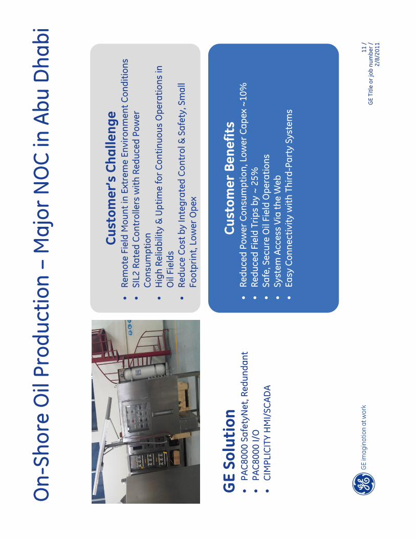
Cust
omer
’s C
halle
nge
•Re
mot
e Fi
eld
Mou
nt in
Ext
rem
e En
viro
nmen
t Con
ditio
ns•
SIL2
Rat
ed C
ontr
olle
rs w
ith R
educ
ed P
ower
C
onsu
mpt
ion
•H
igh
Relia
bilit
y &
Upt
ime
for
Con
tinuo
us O
pera
tions
in
Oil
Fiel
ds•
Redu
ce C
ost b
y In
tegr
ated
Con
trol
& S
afet
y, S
mal
l Fo
otpr
int,
Low
erO
pex
Cust
omer
Ben
efit
s•
Redu
ced
Pow
er C
onsu
mpt
ion,
Low
erC
apex
~10%
•Re
duce
d Fi
eld
Trip
s by
~ 2
5%•
Safe
, Sec
ure
Oil
Fiel
d O
pera
tions
•Sy
stem
Acc
ess
Via
the
Web
•Ea
sy C
onne
ctiv
ity w
ith T
hird
-Par
ty S
yste
ms
GE
Solu
tion
•PA
C80
00Sa
fety
Net
, Red
unda
nt•
PAC
8000
I/O
•C
IMPL
ICIT
Y H
MI/
SCA
DA
On-
Shor
e O
il Pr
oduc
tion
–M
ajor
NO
C in
Abu
Dha
bi

12 /
GE
Title
or
job
num
ber
/2/
8/20
11
Cust
omer
’s C
halle
nge
•Re
mot
e Fi
eld
Mou
nt in
Ext
rem
e En
viro
nmen
t Con
ditio
ns•
Low
Pow
er C
onsu
mpt
ion
•H
igh
Relia
bilit
y &
Upt
ime
for
Con
tinuo
us O
pera
tions
in
Oil
Fiel
ds•
Redu
ce T
CO
Due
to S
mal
l Foo
tpri
nt, L
ower
Ope
x
Cust
omer
Ben
efit
s•
Redu
ced
Pow
er C
onsu
mpt
ion,
Low
erC
apex
~10%
•Re
duce
d Fi
eld
Trip
s by
~ 2
5%•
Safe
, Sec
ure
Oil
Fiel
d O
pera
tions
•Sy
stem
Acc
ess
Via
the
Web
•Ea
sy C
onne
ctiv
ity w
ith T
hird
-Par
ty S
yste
ms
GE
Solu
tion
•PA
C80
00 L
ogic
Con
trol
ler
•PA
C80
00 I/
O•
CIM
PLIC
ITY
HM
I/SC
AD
A
EOR
–C
hem
ical
Inje
ctio
n, S
audi
Ara
bia

Datasheets


PAC8000 RTU Controller PAC8000 RTU Controller 8521-RT-DE
GE Intelligent Platforms 1 800 322 3616 1 434 978 5100
Global Regional phone numbers are available on our website www.ge-ip.com
The PAC8000 RTU was designed from the ground up for the extreme and rugged environments found in today’s most remote process applications. It provides the reliability and uptime you demand to keep your operations running and your business producing. Its open design allows you to interface it with any HMI/SCADA packages such as iFIX, CIMPLICITY, or third party packages. When combined with Proficy Process Systems, it enhances and extends the capabilities of this advanced DCS.
Applications
The PAC8000 RTU Controller is ideal for all types of RTU applications, including those found in the following industries: Oil & Gas Pipelines, Power Generation, Electrical Distribution, and Water and Wastewater.
The Controller platform
The PAC8000 RTU Controller executes your control strategies and manages all control activities for the I/O modules. It provides a tight control loop response, quickly giving a control output in response to input data. It also incorporates a rigorous redundancy model, HART® and Foundation Fieldbus capability, and a fault tolerant Ethernet implementation to manage communications on the control network and deliver reliable operation.
8000 Process I/O™ is a field-mounted distributed I/O system that provides an intelligent interface between field-mounted instrumentation and the PAC8000 RTU Controller. 8000 Process I/O™ interfaces to virtually all process signals providing a com-plete solution for your I/O needs. The complete platform has an environmental specification capable of surviving conditions out in the field.
It is built for harsh environments, being shock and vibration resistant, operating over the industrial –40°C to +70°C temperature range that is typically associated with field transmitters, and meeting ISA's stringent G3 corrosion resistance requirements.
The Controller and I/O components can all be mounted directly in Division 2/Zone 2 hazardous areas and, when required, can provide a cost effective intrinsic safety solution without the need for external barriers. With the PAC8000 RTU Controller and its I/O mounted in the field, the only wiring back to a control room is the high-speed control network.
High Availability - Redundancy
Maximize up-time by incorporating redun-dant controllers, power supplies and net-work connections. 'Hot swap' modules, without affecting operation or re-con-figuring, even in hazardous areas.
Redundant controllers can be used for critical applications. The master/standby pair operate in a rendezvous redundancy mode with frequent status checks to assure a rapid and bumpless transfer to the standby if required. The PAC8000 RTU Controller redundancy model supports on-line configuration and on-line firmware changes, where any updates are shared between controllers in real-time, resulting in an easy to use redundant system. The PAC8000 RTU Controller also supports LAN redundancy. A fully redundant local area network (LAN) can be provided where each controller has two independent Ethernet ports connected to two separate independent networks. The controllers monitor the networks' health and will switch between networks when they detect a problem. Redundant power supplies are available to provide power for critical applications that must not shut down if a power supply malfunctions.
Reduced termination costs
Field wiring goes directly to the I/O terminals in the local field enclosure—no additional cross wiring is required. Integrated Intrinsically Safe (IS) capability mixed with general-purpose signals, together with integral tagging and fusing options, dramatically reduce engineering and design costs.
Flexible system design
Combine analog and discrete modules for maximum flexibility and use of space.
IEC 61131-3 programming
The RTU Controller takes advantage of Windows based object-oriented technology, graphical user interfaces, and easy to learn software solutions to reduce engineering time.
Controller Applications are developed in the PAC8000 RTU Workbench, which fully supports the five IEC 61131-3 automation languages: Ladder Diagram (LD), Sequential Function Chart (SFC), Function Block Diagram (FBD), Structured Text (ST), Instruction List (IL), plus Flow Chart and is used to develop, down-load, simulate, debug, monitor, and edit application programs. It lets you mix pro-gramming languages in the same project. Its true Windows™ interface will guide you through development of your project and use of a simulator will allow you to test your programs before startup. Completed applica-tions are then downloaded to the controller.
On-line changes
The PAC8000 RTU Controller allows online configuration changes during testing, start-up, and maintenance phases. This significantly accelerates system start-up and reduces operation downtime.
Communication Protocols
The PAC8000 RTU Controller supports DNP3 over Ethernet, Modbus TCP/IP, Modbus RTU, and HART Passthrough.
The DNP3 Ethernet implementation supports the select-before-operate (SBO), communication sequence for control operation as well as the Store & Forward & report by exception (RBE).

PAC8000 RTU Controller PAC8000 RTU Controller 8521-RT-DE
IEC 61131-3 language support redundancy with bumpless transfer dual-redundant high-speed Ethernet connections field mountable in harsh process environments low power consumption on-line configuration and reconfiguration HART® pass-through of process and status variables integrated general-purpose and IS signals DNP 3.0 Ethernet Support with NVM Store & Forward
Controller redundancy Redundant controllers can be used for critical applications. The redundant controller pair operates in parallel, checking status multiple times through the processing loop enabling the backup controller to continuously monitor the health of the master controller, assuring a rapid and bumpless transfer to the standby controller.
Network redundancy In addition to controller redundancy, the PAC8000 RTU Controller has two high-speed Ethernet ports to provide security of communication. Each port can be connected to an independent LAN, which is continu-ously monitored for its integrity. If the primary port detects a network failure, traffic is immediately switched to the other LAN to maintain full communication.
Executable control programs The control programs are held in non-volatile memory to enable them to be restored automatically after power cycling of the controller. When redundant controllers are used, both controllers execute the program in lock step redundancy for a bumpless transition to the standby in case of a fault being detected on the master. This allows the standby unit to take over from the master during any point in the execution cycle with no interruption in the control program.
Remote Modbus Devices The PAC8000 RTU Controller communicates via Modbus TCP over Ethernet and can operate in either Modbus Master or Modbus Slave mode to communicate with remote Modbus devices. Each controller also has 2 serial ports that can be configured as a Modbus Master to control and obtain information from Modbus Slaves and other serial devices, such as weigh scales, barcode readers, etc. The serial ports can also be configured as a Modbus Slave, accepting write commands from Modbus Master devices and providing information on its data registers.
Failsafe and automatic cold start In the event of complete loss of communication the controller will adopt a user-defined failsafe mode and similarly instruct the I/O to take up user-defined failsafe values. In the event of power loss the PAC8000 RTU Controller will perform a cold restart, which restores the program(s) and assumes a predefined status. DNP3 over Ethernet DNP is implemented up to Level 3 and supports the select-before-execute (SBE) and communication sequence for control operation as well as the Store & Forward.
I/O module configuration
GE Intelligent Platforms 1 800 322 3616 1 434 978 5100
Global Regional phone numbers are available on our website www.ge-ip.com
The PAC8000 RTU Controller receives full details of all the I/O modules under its control and stores the information in non-volatile memory. At start-up the controller downloads to the modules their
configuration details, which also include the failsafe states they should adopt in the event of communication failure. Firmware updates In keeping with its ability to maintain operations on a continuous basis, a redundant PAC8000 RTU Controller is also capable of receiving a firmware upgrade. In a manner similar to that used for strategy updates, a controller can receive an update to its firmware while in the field. When the upgrade has been confirmed as successful, the controller can be returned to full operation as a master or as a protective standby.
HART® passthrough The PAC8000 RTU Controller has the ability to pass smart HART® information from field devices to a separate PC workstation, which allows you to readily interface to asset management software applica-tions, to remotely manage the HART® information contained in your HART®-based field instruments. The PAC8000 RTU Controller works with a variety of asset management packages,.
Environmental stability Like all of the 8000 series equipment, the PAC8000 RTU Controller is designed for use in harsh environments. It operates over a temperature range of –40°C to +70°C and is resistant to shock, vibration and corrosive environments.
Hazardous area operation The PAC8000 RTU Controller is designed also to operate in Class I, Division 2 and Zone 2 hazardous areas and can connect directly to field devices in the more hazardous Division 1, Zone 1 and Zone 0 areas.
Grows as your needs grow The system is scalable to your needs. You can add modular I/O to your system as your needs increase. Redundant controllers can be added without the need to power off your system - the backup controller powers up automatically and is seamlessly brought online.
Maximum number of nodes Multiple PAC8000 controller nodes can reside on the same network. However, too many nodes can degrade performance, so GE recommends placing no more than 25 nodes on the same subnet of a network. Each network can contain up to 255 such subnets.

PAC8000 RTU Controller PAC8000 RTU Controller 8521-RT-DE
8000 Process I/O™ hardware
Overview 8000 Process I/O is a completely modular I/O solution for both general purpose and hazardous area applications. It is based on a carrier system that supports a range of modules and offers a wide variety of I/O functions, including AC mains and intrinsic safety signals, even within the same node. I/O Modules I/O modules transfer signals to and from field instruments. Input modules receive
signals from transmitters and sensors and convert them into a digital form for presentation to the Controller.
GE Intelligent Platforms 1 800 322 3616 1 434 978 5100
Global Regional phone numbers are available on our website www.ge-ip.com
Output modules receive commands from the Controller
and transfer them available, including types for low-level instrumentation, AC mains and intrinsically safe signals, I/O modules typically have 4, 8 or 16 field channels.
Field terminals Field terminals provide the interface between the I/O modules and the field wiring. They include fusing and loop-disconnect as options. A mechanical keying system prevents an I/O module from being connected to the wrong type of field terminal. Field terminals mount onto
the module carrier, one to each I/O module. They are clamped firmly by the I/O module to form an
electrical and mechanical assembly of high integrity. They may be replaced in service without removing carriers or disturbing the operation of other modules.
Carriers Carriers form 8000's physical and electrical backbone by providing a mounting to support and interconnect the controller, power supplies, I/O modules and field terminals, and carry the address, data and
power lines of the internal Railbus. They
provide termination points for the LAN and field wiring cable shields and can also distribute bussed field power to the I/O modules. I/O module carriers are available to support four or eight I/O modules.
System power supplies System power supplies are available for
the node to convert local AC or DC supplies to power the node or provide field power for I/O modules. 8000's
innovative Bussed Field
Power scheme for distributing field power avoids complex wiring at the field terminal and minimizes the carrier wiring.
'HART-ability' The use of 'smart' instruments on process plants is growing but this investment is not always fully exploited. Whether it is for a new installation, or the upgrade of an existing one, GE has solutions that provide the connections between the HART field instruments, the control systems and the process automation maintenance software. Specifically, the 8000 Process I/O system has been designed to be transparent to HART signals, thus allowing the host control software and any HART field instruments to communicate directly with each other. In addition, 8000’s HART connection system provides on-line access from a PC to the HART field devices for monitoring device performance. HART devices may be selected for regular status monitoring and alerts can be issued if the status changes. The benefits from this approach are: · reduced commissioning time and cost · reduced process downtime through status monitoring power loop maintenance costs by using field device diagnostics.
8000 Process I/O in your system Each PAC8000RTU node can address up to 64 I/O modules which, depending upon the number of channels per module, can pro-vide up to 1024 I/O points at a single node! A node can consist of a mixture of analog and discrete modules and this gives maximum flexibility to the system designer. Full HART pass-through is provided - the 8000 appears "transparent", allowing the inquiring "agent" to access the HART capabilities of field instruments. GE recommends placing no more than 25 nodes on the subnet of a network.
Redundancy options 8000 Process I/O has been designed to increase availability and minimize downtime. Redundant controllers, LAN Channels and power supplies can be specified as options to increase system availability. Possible down-time is further reduced by ensuring that the system components using active circuitry can be removed and replaced quickly and easily. Even the field terminals can be replaced without interrupting the operation of adjacent I/O modules. Carriers have no active circuitry and are unlikely to need replacement.
Hazardous area applications The 8000 Process I/O is a truly field mountable system even in areas where flammable gases are present. It is available in versions to suit different area classification schemes:
a) Equipment and field wiring located in general purpose areas, Class 1, Division 2 hazardous locations or Zone 2 hazardous areas.
b) Equipment mounted in general purpose areas, Class 1, Division 2 hazardous locations or Zone 2 hazardous areas, with field wiring located in Division 1 hazardous locations or Zone 0 hazardous areas.

PAC8000 RTU Controller PAC8000 RTU Controller 8521-RT-DE
A control node Many industry applications do not present an explosion risk from gas or dust hazards. In others, the environment may be classified as a Zone 2 or Division 2 hazardous area, where flammable material is expected to occur only in abnormal conditions. For both of these the 2/2 system provides effective distributed I/O for process control. 8000 supports a full range of I/O module types covering inputs and outputs for both analog and discrete circuits. The node can be mounted out on the plant in a suitable enclosure that is capable of providing protection against the environment. The diagram shows a node containing the basic components: one (or two) PAC8000 RTU Controllers, I/O modules on their carriers linked by carrier-extenders and an extension cable.
8000 with intrinsic safety field wiring The 8000 Process I/O System is also capable of supporting I/O modules with intrinsic safety (IS) field wiring, for connection to certified or 'simple apparatus' field devices in Division 1 or Zone 0 hazardous areas. A range of I/O module types with IS field circuits for industry-standard DI, DO, AI, AO and pulse applications is supported.
Integrated power supplies Power for IS I/O modules is derived from integrated, modular power supply units. Each power unit is capable of supplying between eight and twenty I/O modules, depending on the I/O type and mix. Optional power supply redundancy is supported by means of an additional, redundant supply unit connected in a 'n+1' arrangement. In applications with mixed IS and non-IS field wiring, the full facilities of the 'Bussed Field Power' regime are retained for the non-IS part of the system. In nodes populated only with IS I/O modules, a separate system power supply module provides power for the Bus Interface Module and 'node services'. Redundancy of this supply is also supported.
PAC8000 RTU Controller The mission of GE is to design, manufacture and distribute modular, open hardware and software technology-based components for use in the most demanding real-time system applications. These field-proven components can be “snapped” together to create sophisticated control systems.
Controller Specification Clock Speed: 266 MHz, 16 MB Ram, 1MB NV Ram, 8 MB Flash LAN INTERFACE Transmission medium.............................100BaseTX or 10BaseT Ethernet™
Transmission protocol ......DNP and Modbus™ over high-speed Ethernet™ Transmission rates ......................................................................10 - 100 Mbits/s
GE Intelligent Platforms 1 800 322 3616 1 434 978 5100
Global Regional phone numbers are available on our website www.ge-ip.com
LAN connector type (x2) ...................................................................RJ 45 (8-pin) LAN isolation (dielectric withstand) ......................................................1500 V Action on software malfunction ……………………...... Halt CPU / Reset CPU Max. nodes on a subnet of a network.............................................................25 Max. subnets on a network……………………………………………………………………….255
SERIAL INTERFACES (COM 1 & COM 2) Transmission rates...................... 1.2 – 115.2 kbits/s (async.) Transmission standard .......………………………….....................RS485 half-duplex COM 1 connector (on carrier) ..…………………..... 9-pin D-type connector (F) COM 2 connector (on controller) ……………...9-pin D-type connector (M) POWER SUPPLIES Voltage............................................................................................... 10.9 – 12.6 V dc Current...........................................................................................................0.4 A ( typ.) ........................................................................................…….............................. 0.5 A (max.)
HAZARDOUS AREA APPROVALS Location of equipment........... Zone 2, IIC T4 hazardous area .........or Class 1, Div 2, Groups A, B, C, D T4 hazardous location Applicable standards: Factory Mutual Research Co., Class No. 3611 for Class I, Division 2,
Groups A, B, C, D hazardous locations CSA Std C22.2 No.213 for Class I, Division 2, Groups A, B, C, D
hazardous locations ATEX Category 3 (for Zone 2 installation) to EN50021:1999
protection type n. UL 61010-1 “Safety Requirements for Electrical Equipment for
Measurement, Control, and Laboratory Use; Part 1: General Requirements, 2nd Edition
See System Specification Guide for other parameters MECHANICAL Module dimensions.................. 69 (w) x 232 (l) x 138 (h) mm Weight (approx.) ..................................................... 1.35 kg Modbus™ is a trademark of Schneider Automation Inc HART® is a registered trademark of the HART Communication Foundation

PAC8000 SafetyNet
♦ SIL2 certified 1oo1D (single Controller with diagnostics) ♦ Process Control & Safety Functions from a single platform ♦ Mix standard and SafetyNet Modules on the same nod
♦ Single programming environment for Process, Logic and Safety Applications ♦ On-line changes supported ♦ Mounts in harsh and hazardous Environments
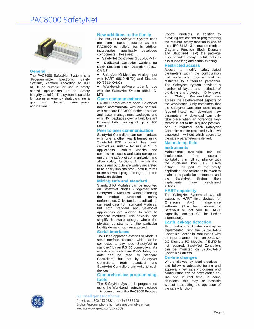
The PAC8000 SafetyNet System is a new addition to the GE’s product family. Sharing the same fundamental platform as the PAC8000 controllers, a new SafetyNet Controller, a new Earth Line Fault Detect (ELFD) Controller Carrier and two new SafetyNet IO Modules have been developed and certified. The SafetyNet System uses the same field terminals, I/O Module Carriers and Power Supplies as the Process Control products. Configuration and application design is carried out using software tools specifically safety applications -but within a common programming environment.
Certified according to IEC 61508 as a "Programmable Electronic Safety System", PAC8000 SafetyNet is suitable for use in safety-related applications up to Safety Integrity Level (SIL) 2. As part of the family of open system components designed for the process automation market, it can be closely integrated with the Proficy Process Control System or used as a standalone safety system working alongside any Process Control solution. The system will also operate "openly" with your choice of HMI - whatever package you use.
Emergency Shutdown, Fire & Gas and Burner Management application requirements are all met, with certification to IEC 61511 for process industries and NFPA 85 for burner management systems.
Designed for SIL 2, the SafetyNet System has been specifically developed for safety applications, with features that ensure safety designed in to the product, with a simple and straightforward Safety Manual. The net result is a product that is easy to program, configure and use.
The modular approach provides cost effective solutions to safety applications with limited I/O counts per node. And since each SafetyNet node can accommodate up to 64 I/O modules, (each of 8 channels), the requirements of safety systems with high I/O counts are also met.
Using a 1 out of 1 with diagnostics structure(1oo1D), a single controller, input module and output module (together with the necessary field terminals, carriers and power supplies and a suitable sensor and final element) meet all the requirements of a SIL 2 safety function.
Redundant controllers can be used to improve availability for the SIL 2 safety function - with entirely bumpless transfer. Further availability enhancements can be made by the use of redundant, fault tolerant Ethernet communications and redundant power supplies.
GE Intelligent Platforms Americas: 1 800 433 2682 or 1 434 978 5100 Global Regional phone numbers are available on our website www.ge-ip.com/contacts
Page:1
PAC8000 SafetyNet
General The PAC8000 SafetyNet System is a "Programmable Electronic Safety System", certified according to IEC 61508 as suitable for use in safety related applications up to Safety Integrity Level 2. The system is suitable for use in emergency shutdown, fire & gas and burner management applications.
New additions to the family The PAC8000 SafetyNet System uses the same basic structure as the PAC8000 controllers, but in addition incorporates specifically developed components. These are: ♦ SafetyNet Controllers (8851-LC-MT) ♦ Dedicated Controller Carriers for Earth Leakage Fault Detection (8751-CA-NS) ♦ SafetyNet IO Modules -Analog Input with HART (8810-HI-TX) and Discrete IO (8811-IO-DC) ♦ Workbench software tools for use with the SafetyNet System (8841-LC-MT) Open communications PAC8000 products are open. SafetyNet nodes communicate with one another, with standard PAC8000 nodes, historian and asset management packages and with HMI packages over a fault tolerant Ethernet LAN, running at up to 100 Mbit/s. Peer to peer communication SafetyNet Controllers can communicate with one another via Ethernet using SafetyNet P2P - which has been certified as suitable for use in SIL 2 applications. Robust checks and controls on access and data corruption ensure the safety of communication and allow safety functions for which the inputs and outputs are widely separated to be easily implemented - both in terms of the software programming and in the hardware design. Mixing safe and standard Standard IO Modules can be mounted on SafetyNet Nodes - together with SafetyNet IO Modules - without affecting the node's functional safety performance. Only standard applications can read data from standard Modules, but both standard and SafetyNet applications are allowed to write to standard modules. This flexibility can simplify hardware design, where the physical constraints of the particular locality demand such an approach. Serial interfaces The Open approach extends to Modbus serial interface products - which can be connected to any node (SafetyNet or standard) by an RS485 connection. As with data from standard IO Modules, this data can be read by standard Controllers, but not by SafetyNet Controllers. Both standard and SafetyNet Controllers can write to such devices. Comprehensive programming tools
GE Intelligent Platforms Americas: 1 800 433 2682 or 1 434 978 5100 Global Regional phone numbers are available on our website www.ge-ip.com/contacts
Page:2
The SafetyNet System is programmed using the Workbench software package – in common with the PAC8000 Process
Control Products. In addition to providing the options of programming the required safety function in one of three IEC 61131-3 languages (Ladder Diagram, Function Block Diagram and Structured Text) the package also provides many useful tools to assist in testing and commissioning. Restricted access Access to modify safety-related parameters within the configuration and application program must be restricted to authorized personnel. The SafetyNet system provides a number of layers and methods of providing this protection. Only users with "Safety Responsibility" can access the safety-related aspects of the Workbench. Only computers that the SafetyNet Controller identifies as "trusted hosts" can download new parameters. A download can only take place when an "over-ride key-switch" is set to the required position. And, if required, each SafetyNet Controller can be protected by its own password - without which access to the safety parameters is denied. Maintaining field instruments Maintenance over-rides can be implemented from operator workstations in full compliance with the guidelines from TUV. Users define - as part of the safety application - the actions to be taken to maintain a particular instrument and the SafetyNet System then implements these pre-defined actions. HART capability The SafetyNet System allows full access to HART field devices for Emerson's AMS maintenance software. (The first release of SafetyNet will not have full HART capability, contact GE for further information). Earth leakage detection Earth leakage fault detection may be implemented using the 8751-CA-NS Controller Carrier in conjunction with an input channel from an 8811-IO-DC Discrete I/O Module. If ELFD is not required, SafetyNet Controllers can be mounted on 8750-CA-NS Controller Carriers. On-line changes Where allowed by local practices – and following adequate testing and approval - new safety programs and configuration can be downloaded on-line and in real time. In some situations, this may be possible without interrupting the operation of the safety function.

PAC8000 SafetyNet
Harsh and Hazardous Environments The SafetyNet System is as rugged as the other PAC8000 Controller and 8000 Process I/O Components: -40ºC to +70ºC operating ambient temperature; Zone 2 or Class 1 Division 2 hazardous area mounting; G3 corrosion resistance; and enhanced shock and vibration capability. The system will operate in the PAC8000 extreme environments found in process industries, allowing remote mounting and a truly distributed architecture in even the most demanding situations.
Event Logging and Sequence of Events Recording The SafetyNet System has the same Event Logging and Sequence of Events (SOE) recording capability as the PAC8000 Controllers. Data received from SafetyNet Modules is time-stamped by the SafetyNet Controller with a resolution of better than 200ms (this is dependent on the execution cycle - small nodes will deliver better resolution). Data from dedicated (non-SIL) SOE modules is time-stamped with a resolution of less than 0.25ms between different channels of the same SOE module and less than 1ms between channels from different SOE modules. The SafetyNet Controller can record up to 8000 events before its event data buffer begins to be overwritten by new data.
Reduced cabling and termination costs In common with the PAC8000 Controllers, the SafetyNet System offers users the opportunity to significantly reduce their spending on wiring and termination costs. Moving control and safety hardware out of the control room and on to the plant gives significant savings. The Field Terminal design allows users to avoid unnecessary spend on marshalling cabinets, cross wiring and marshalling terminals. Integral tagging and fusing further simplifies cabinet design and installation.
GE Intelligent Platforms Americas: 1 800 433 2682 or 1 434 978 5100 Global Regional phone numbers are available on our website www.ge-ip.com/contacts
Page:3

PAC8000 SafetyNet
Figure 1 – typical PAC8000 SafetyNet System layout PAC8000 SafetyNet on your plant Figure 1 shows a typical layout of a PAC8000 SafetyNet System, together with a PAC8000 Controller, an OPC Server, an HMI and asset management and historian packages all connected together via an Ethernet LAN. Also shown is the PAC8000 Workbench - the dedicated tool for programming and configuring PAC8000 SafetyNet
GE Intelligent Platforms Americas: 1 800 433 2682 or 1 434 978 5100 Global Regional phone numbers are available on our website www.ge-ip.com/contacts
Page:4
and PAC8000 ontroller.
that eed to be made are also shown.
C
ode layout and SafetyNet npowering Figure 2 shows a typical layout of a SafetyNet node, with Controllers, IO Modules, Field Terminals, and Carriers. The power connections n

PAC8000 SafetyNet Fault Tolerant Redundant LAN The availability of Ethernet connections - between SafetyNet and standard Controllers, historian and asset management packages and HMI stations - has a significant impact on the effectiveness and availability of both safety and control functions. To maximise availability of the Ethernet LAN, PAC8000 SafetyNet Systems feature Fault Tolerant Ethernet ports that monitor the integrity of their local network and automatically switch to an alternate path if the existing path becomes unavailable. If suitable Ethernet switches are used - such as Moxa Industrial Ethernet Switches - they too will monitor their local network and switch to an alternative path when this is required. Monitoring the local network paths – even when they are not being used - allows the system to report the loss of any failed paths so that appropriate maintenance can be carried out. Moxa Industrial Ethernet Switches The Moxa Ethernet Switch range is specifically designed for use in Industrial applications that require high availability in harsh environments, with a broad operating temperature range (-40ºC to +75ºC, except EDS-205: -10ºC to +60ºC) and hazardous area mounting capability (Class 1, Div 2 or Zone 2). Two alternative topologies are shown in figures 1 and 2. Which topology is preferred will depend on the physical layout of the entities on the LAN and local preferences. Figure 1 shows a redundant Ethernet LAN, with intra-LAN link while figure 2 shows a single "Turbo Ring" that provides an alternate means of ensuring Ethernet availability -implemented in the Moxa EDS405 5-port switch. If any part of the Turbo Ring fails, communication is re-routed automatically within 300ms. Further improvements to availability can be achieved by putting in place a second identical, "Turbo Ring" which should be connected to the first ring by a single intra-LAN link. This link would normally be mounted in the control room. The Moxa switches are available with either all copper or a combination of copper and fibre ports. For media conversion between fibre and copper the MOXA IMC-101 can be used. All the Moxa products (except the EDS-205) have dual power supply inputs and a relay output for user configurable fault reporting.
Figure 1 - redundant Ethernet LAN with intra-LAN link
Figure 2 - “Turbo Ring” Ethernet LAN
GE Intelligent Platforms Americas: 1 800 433 2682 or 1 434 978 5100 Global Regional phone numbers are available on our website www.ge-ip.com/contacts
Page:5

PAC8000 SafetyNet
GE Intelligent Platforms Americas: 1 800 433 2682 or 1 434 978 5100 Global Regional phone numbers are available on our website www.ge-ip.com/contacts
Page:6
Certification The SafetyNet Controller is certified for use in safety-related applications up to and including SIL 2. The SafetyNet Controller achieves this Safety Integrity Level with a 1oo1D architecture (i.e. it operates in "simplex" mode, with correct operation ensured by comprehensive internal diagnostics). In such applications the SafetyNet Controller is used in conjunction with the 8811-IO-DC SafetyNet Digital Input/Output Module and the 8810-HI-TX SafetyNet Analog Input Module with HART*. The SafetyNet Controller is mounted on its dedicated Carrier 8751-CA-NS. *First release of SafetyNet will not have full HART capability.
General The 8851-LC-MT SafetyNet Controller stores and runs the SafetyNet application program which is downloaded from the Workbench. It manages a number of communication paths: with the IO Modules mounted on the local node via the internal Railbus; with other entities on the Ethernet LAN (other PAC8000 nodes, PCs running the Workbench programming tools, HMI, historian packages and asset management tools) and with remote mounted serial devices. The SafetyNet Controller also manages the implementation of the redundancy strategy either as master or standby.
Safe by design The SafetyNet Controller has been designed specifically for safety-related applications and is certified on the basis of the excellence of its design. It does not depend for its certification on "proven in use" data. Diagnostics If the SafetyNet Controller's internal diagnostics detect a fault that would prevent the SafetyNet System from carrying out its safety function, then it will initiate a controlled shutdown. A controlled shutdown has two objectives - firstly, to ensure that the SafetyNet System enters its failsafe mode; and secondly, to record sufficient data to allow the reason for the shutdown to be determined. If a SafetyNet Controller enters a controlled shutdown, then all communication with IO Modules is stopped and - when the programmed time delay for each IO module has elapsed - they will enter their safe states. System size The SafetyNet Controller can interface with up to 64 locally mounted, 8-channel IO Modules - giving a total capacity of over 500 channels per node. The Ethernet LAN is capable of supporting over 200 nodes, giving a maximum theoretical capacity of over 100 000 channels! HART pass-through SafetyNet Controllers can be configured to allow transparent access to the process variables and status information provided by HART field instruments. HART data cannot be used within the SafetyNet application (as - for example - it does not employ sufficiently rigorous data error detection algorithms), but communication with such devices can be achieved by using a "passthrough" command which does not involve, nor
interfere with, the safety application. (The first release of SafetyNet will not have full HART capability, contact GE for further information). Live maintenance Once the Ethernet LANs are isolated, SafetyNet Controllers can be removed and replaced - with the local power supplies still connected - even in Division 1, Class 2 or Zone 2 hazardous areas. Redundant Controllers SafetyNet Controllers can be used in a master - standby redundant configuration to improve the availability of the safety function, but this is not required for safety. Redundancy is implemented by simply inserting the new Controller in to the free slot on the Controller Carrier. The SafetyNet system will automatically upload the required SafetyNet application to the new Controller and initiate the redundancy algorithms. Switching between redundant Controllers on detection of a fault is automatic and bumpless. The standby Controller continually performs the same processing, on the same data and at the same time as the Master and the results are routinely cross-checked. This ensures that the Standby is always ready to take over control from the Master. The redundancy strategy employed is known as "rendezvous redundancy". The "Change State" button on the Controller Carrier is used to switch a master to being the standby in a redundant pair, to switch a standby offline and to instruct an offline standby Controller to synchronise itself with the Controller and to enter standby. If a SafetyNet Controller has entered the “Failsafe” state, it can be brought out of this state by use of the “Change State” button. Serial communications Each SafetyNet Controller provides two serial ports - one of which is physically connected via the Controller Carrier, the other directly on the Controller itself. The two ports can be configured to be entirely independent, or can be made to work redundantly, either as redundant connections to the same serial link or as redundant connections to redundant links. When redundant ports of a single Controller are configured as Modbus masters, redundancy issues are handled automatically by the SafetyNet Controller deciding when to switch to the standby port, alarming failures in the standby). When redundant ports of a single Controller are configured as Modbus slaves and multi-dropped on a single serial link, the SafetyNet Controller will again manage the redundancy (deciding which port respond to the Modbus master and alarming a fault in the standby port). When redundant Controllers are used, this adds additional availability to the arrangements above. It is not possible to use the ports on the standby Controller as additional serial connections.

PAC8000 SafetyNet
SafetyNet Controller 8851-LC-MT Certified for use in SIL 2 safety applications, according to IEC 61508 Comprehensive internal diagnostics provide basis for safety architecture 1oo1D Optional redundancy with bumpless transfer for increased availability Dual redundant high speed fault tolerant Ethernet LAN Two connections to serial devices On-line configuration and re-configuration Communicates with up to 64 I/O modules Communicates on peer-to-peer basis with other SafetyNet and standard Controllers Can write to standard output modules without compromising safety function Live maintainable and hot-swappable - even in Class 1, Div 2 or Zone 2 hazardous areas HART pass-through of process and status variables Event logging up to 8000 events 12Vdc Controller power required from 8913-PS-AC CONTROLLER SPECIFICATION See also System Specification LAN INTERFACE Transmission medium...............100BaseTX or 10BaseT Ethernet™ Transmission protocol......................................................SafetyNet P2P* Transmission rates ..........................................................10 - 100 Mbits/s LAN connector type (x2) .........................................................RJ 45 (8-pin) LAN isolation (dielectric withstand)............................................1500 V Action on software malfunction ………..........Halt CPU / Reset CPU * SafetyNet P2P is a modified form of Modbus™ certified as suitable for use in SIL 2 safety related applications that require peer-to-peer communication. SERIAL INTERFACES (COM 1 & COM 2) Transmission rates...................................1.2 – 115.2 kbits/s (async.) Transmission standard..........................................RS485 half-duplex COM 1 connector (on carrier) .............9-pin D-type connector (F) COM 2 connector (on controller) .......9-pin D-type connector (M) HAZARDOUS AREA SPECIFICATION Protection Technique..........................................................EEx nL IIC T4 Location (FM and CSA) ...................Class 1, Div.2, Grps A,B,C,D T4
POWER SUPPLIES Controller Power Voltage................12V dc (from 8913-PS-AC) Controller Power Supply…………..........0.4A (typical), 0.5A (max.) System Power Supply......................................................15mA (max.) MECHANICAL Module dimensions ........................69 (w) x 232 (l) x 138 (h) mm Weight (approx.).............................................................................1.35kg
GE Intelligent Platforms Americas: 1 800 433 2682 or 1 434 978 5100 Global Regional phone numbers are available on our website www.ge-ip.com/contacts
Page:7

PAC8000 SafetyNet LED's The SafetyNet Controller has a number of LED’s that indicate the status and mode of operation of the Controller. The table below explains what they refer to and describes their operation: Note: the information here given here is simplified. Additional combinations of LED states are used to provide further indication of the status of the SafetyNet Controllers. Full details are found in the relevant instruction manuals.
GE Intelligent Platforms Americas: 1 800 433 2682 or 1 434 978 5100 Global Regional phone numbers are available on our website www.ge-ip.com/contacts
Page:8

PAC8000 SafetyNet
GE Intelligent Platforms Americas: 1 800 433 2682 or 1 434 978 5100 Global Regional phone numbers are available on our website www.ge-ip.com/contacts
Page:9
Workbench for SafetyNet – Overview PAC8000 Workbench The PAC8000 Workbench is the engineering and documentation tool for the PAC8000 Controllers and SafetyNet Systems. The Workbench is used to perform the following tasks: ♦ Configure IO Channel and Module parameters ♦ Configure Controller and network parameters ♦ Input and manage the IO tag database ♦ Engineer and document the control or safety application ♦ Generate wizards to simplify HMI design ♦ Simulate and test control and safety applications ♦ Generate reports to assist in Factory and Site Acceptance Testing
SafetyNet Workbench The SafetyNet Workbench (8841-LC-MT) has all the features of the standard Workbench, but additionally includes the special tools required for safety applications. Safety programming languages The Workbench provides three IEC61131 programming languages that can be used to write safety-related application programs: ♦ Ladder logic (LD) ♦ Function Block Diagram (FBD) ♦ Structured Text (ST) Configuration Mode and Safety Responsibility Changes to safety-related parameters are carried out with the SafetyNet Controller in “Configuration Mode”. Access to this mode is restricted to personnel with “Safety Responsibility” and its use is constrained by a number of further layers of protection for downloading parameters to SafetyNet Controllers. The SafetyNet system defines 6 password protected levels of access authority – with only the 3 highest levels being granted “Safety Responsibility”. Trusted Hosts To prevent access to SafetyNet Controllers by non-approved instances of the Workbench, remote Modbus devices, asset management packages and HMI, only those that the SafetyNet Controller identifies as “Trusted Hosts” can download new parameters. Each Trusted Host is recognised by its IP and MAC addresses (remote Modbus devices are recognised by the serial port to which they are connected). For each Trusted Host a number of other restrictions can be defined: ♦ Modbus write not allowed ♦ Workbench write not allowed ♦ HART pass-through not allowed Key Switch Protection When a SafetyNet Controller is added to the Workbench the user is given the option of selecting a tag to act as a “Key Switch”. This can be used by an Operator to lock the SafetyNet System so that Configuration Mode cannot be entered without their awareness or permission. The Key Switch can be a physical switch, driven from an HMI screen or it can be an output from the SafetyNet application. Controller Passwords When a SafetyNet Controller is added to the Workbench the user is given the option to use a Controller Password. If this option is selected, it is subsequently impossible to
enter Configuration Mode without the Controller Password. On-line download Users with safety responsibility can download new parameters to a SafetyNet Controller, from a Trusted Host, to a Controller whose Key Switch is set to permit new downloads and where the particular SafetyNet Controller’s Password is known. New parameter download is carried out as a background task over a number of cycles to ensure that the fault reaction and response times are not compromised. Once download is complete and the new parameters have passed the checking and security tests, the new parameters will be automatically adopted. Where redundant SafetyNet Controllers are used, the stand-by Controller will also be automatically updated. Note: on-line download should only be used where there are adequate procedures for approving the changes that have been made and testing them prior to download. Static Analysis Tool Any safety-related application program must be developed by suitably qualified personnel and must be subject to careful scrutiny to ensure safety, but the Workbench provides an additional safety test. The Static Analysis Tool checks for illegal constructs within the safety program prior to download. Differences Utility Once a new SafetyNet application is successfully compiled, it can be downloaded to a SafetyNet Controller. On download, two text reports are generated: a Download Report and a Master Tag Xref. These can be used for comparison with other downloads using the Differences Utility. Download backup A time stamped backup of each safety application is automatically created following a successful download. Changes between versions can be viewed and backups can be used either as a start point for developing new safety applications or to restore an earlier version. Change Control Log The Workbench maintains a Change Control Log that records - for example - when: ♦ IO Modules are added, deleted or moved ♦ Tags are added to, removed from, or moved within an IO Module ♦ IO Configuration parameters are saved ♦ Controller IP addresses or node numbers are entered or modified ♦ External node numbers are entered or modified ♦ Serial communications parameters are entered or modified ♦ A successful download is made ♦ A Strategy is removed ♦ The Controller password is changed
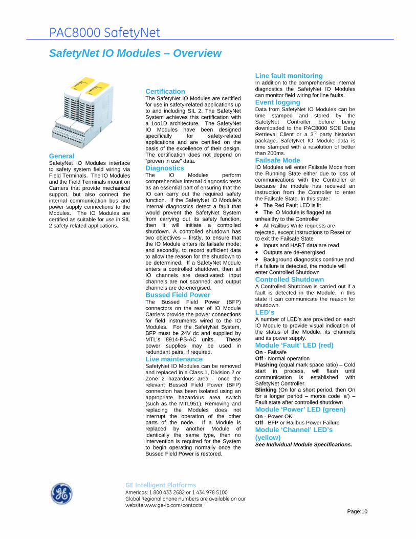
PAC8000 SafetyNet
SafetyNet IO Modules – Overview
General SafetyNet IO Modules interface to safety system field wiring via Field Terminals. The IO Modules and the Field Terminals mount on Carriers that provide mechanical support, but also connect the internal communication bus and power supply connections to the Modules. The IO Modules are certified as suitable for use in SIL 2 safety-related applications.
Certification The SafetyNet IO Modules are certified for use in safety-related applications up to and including SIL 2. The SafetyNet System achieves this certification with a 1oo1D architecture. The SafetyNet IO Modules have been designed specifically for safety-related applications and are certified on the basis of the excellence of their design. The certification does not depend on “proven in use” data. Diagnostics The IO Modules perform comprehensive internal diagnostic tests as an essential part of ensuring that the IO can carry out the required safety function. If the SafetyNet IO Module’s internal diagnostics detect a fault that would prevent the SafetyNet System from carrying out its safety function, then it will initiate a controlled shutdown. A controlled shutdown has two objectives – firstly, to ensure that the IO Module enters its failsafe mode; and secondly, to record sufficient data to allow the reason for the shutdown to be determined. If a SafetyNet Module enters a controlled shutdown, then all IO channels are deactivated: input channels are not scanned; and output channels are de-energised. Bussed Field Power The Bussed Field Power (BFP) connectors on the rear of IO Module Carriers provide the power connections for field instruments wired to the IO Modules. For the SafetyNet System, BFP must be 24V dc and supplied by MTL’s 8914-PS-AC units. These power supplies may be used in redundant pairs, if required. Live maintenance SafetyNet IO Modules can be removed and replaced in a Class 1, Division 2 or Zone 2 hazardous area - once the relevant Bussed Field Power (BFP) connection has been isolated using an appropriate hazardous area switch (such as the MTL951). Removing and replacing the Modules does not interrupt the operation of the other parts of the node. If a Module is replaced by another Module of identically the same type, then no intervention is required for the System to begin operating normally once the Bussed Field Power is restored.
Line fault monitoring In addition to the comprehensive internal diagnostics the SafetyNet IO Modules can monitor field wiring for line faults. Event logging Data from SafetyNet IO Modules can be time stamped and stored by the SafetyNet Controller before being downloaded to the PAC8000 SOE Data Retrieval Client or a 3rd party historian package. SafetyNet IO Module data is time stamped with a resolution of better than 200ms. Failsafe Mode IO Modules will enter Failsafe Mode from the Running State either due to loss of communications with the Controller or because the module has received an instruction from the Controller to enter the Failsafe State. In this state: ♦ The Red Fault LED is lit ♦ The IO Module is flagged as unhealthy to the Controller ♦ All Railbus Write requests are rejected, except instructions to Reset or to exit the Failsafe State ♦ Inputs and HART data are read ♦ Outputs are de-energised ♦ Background diagnostics continue and if a failure is detected, the module will enter Controlled Shutdown Controlled Shutdown A Controlled Shutdown is carried out if a fault is detected in the Module. In this state it can communicate the reason for shutdown. LED’s A number of LED’s are provided on each IO Module to provide visual indication of the status of the Module, its channels and its power supply. Module ‘Fault’ LED (red) On - Failsafe Off - Normal operation Flashing (equal:mark space ratio) – Cold start in process, will flash until communication is established with SafetyNet Controller. Blinking (On for a short period, then On for a longer period – morse code ‘a’) – Fault state after controlled shutdown Module ‘Power’ LED (green) On - Power OK Off - BFP or Railbus Power Failure Module ‘Channel’ LED’s (yellow) See Individual Module Specifications.
GE Intelligent Platforms Americas: 1 800 433 2682 or 1 434 978 5100 Global Regional phone numbers are available on our website www.ge-ip.com/contacts
Page:10

PAC8000 SafetyNet
SafetyNet Analog IO Module – Overview
General The SafetyNet Analog Input Module with HART provides the interface to 8 channels of 4-20 mA input signals. The SafetyNet Analogue Input Module is certified for use in safety-related applications up to SIL 2. In such applications the module is used with the 8851-LC-MT SafetyNet Controller and 8811-IO-DC SafetyNet Discrete Input/Output Module.
GE Intelligent Platforms Americas: 1 800 433 2682 or 1 434 978 5100 Global Regional phone numbers are available on our website www.ge-ip.com/contacts
Page:11
Diagnostics The SafetyNet Analogue Input Module carries out a number of diagnostic checks to confirm the accuracy of the measurement reported and the correct operation of the module. In addition to the primary measurement, a second diagnostic measurement is made using different internal circuitry. The two values are then compared. The primary measurement is reported as faulty if it differs from the diagnostic measurement value by more than 2%. Further tests are carried out on internal supply and references voltages. If a particular channel fails a test, then that channel is made inactive. If the failed test indicates that the Module is not working correctly, it will enter Controlled Shutdown. Live maintenance The field wiring connections to the SafetyNet Analogue Input Module are classified as non-incendive and can therefore be live worked in a Class 1, Division 2 or Zone 2 hazardous area. (Note the Bussed Field Power connection must be isolated before the module is removed or replaced). Input sampling and filtering Each input channel is sampled once every 25ms and is filtered by 1st order hardware and software filters. The software filter can be disabled or set to a number of different values according to the filtering requirements of each channel. HART capability The HART capabilities of the Analogue Input Module allow acquisition of
secondary variables – which can be used by a standard (but not SafetyNet) application program. The Module also allows Emerson’s AMS package to communicate with any HART field device transparently, using HART pass-through. (The first release of SafetyNet will not have full HART capability, contact GE for further information). LED’s For the operation of the Power and Fault LED’s see IO Module Overview. Module ‘Channel’ LED’s (yellow) On – Channel in range (4-20mA) Off – Channel inactive Flashing (equal:mark space ratio) – Any of the following, with an active channel: line fault (indicated by the input measurement being outside the 4-20mA range), loss of HART signal, Hi-Hi or Lo-Lo alarm. Alarms, Deadband, Dead Zone The Analogue Input Module has a number of configurable parameters for managing setting and clearing alarms and triggering the reporting of a new input value. Hi, Hi-Hi, Lo and Lo-Lo alarms can be configured – together with a Deadband through which the input must move before the alarm is cleared. The relationship between these parameters is shown in the diagram below. A Dead Zone can also be configured, which is the value by which an input measurement must change before it is reported as a new value.

PAC8000 SafetyNet
SafetyNet Analogue Input Module 4-20 mA with HART 8810-HI-TX ♦ 8 single ended 4-20mA input channels ♦ Certified for use in SIL 2 safety applications ♦ Non-incendive field circuits ♦ 2-, 3- or 4-wire transmitters ♦ HART pass-through, acquisition and status reporting* ♦ 24V dc Bussed Field Power required from 8914-PS-AC MODULE SPECIFICATION See also System Specification INPUTS Number of channels ........................................8, single-ended Nominal signal range (span) ....................................4 to 20mA Full signal range ..................................................0.25 to 24mA Line fault detection Short circuit current .....................................................> 23.5mA Open circuit current ......................................................< 0.5mA Output voltage (@ 20mA)......................................10.2V (min.) Output current ......................................................28mA (max.) Accuracy (at 25oC) ............................................± 0.1% of span Temperature coefficient ...........................................38 ppm/C Resolution ......................................................................16 bits Repeatability ......................................................0.05% of span Data format ....................16-bit unsigned (0-25mA = 0-65,535) HART data format ..................................IEEE754 floating point Isolation (any channel to Railbus) .......................................250V ac RMS (between channels) ............................................................none CONFIGURABLE PARAMETERS Alarms. ..................................high, high-high, low and low-low Alarm deadband (hysteresis) .......................user defined value Input filter time constant ............................user defined value Input dead zone ...........................................user defined value Drive on fault state .....................disabled /upscale /downscale HART variable and status reporting .............. enable /disable RESPONSE TIME Signal change to availability on Railbus 4– 20 mA mode ......................................................25ms (max.) HART mode....................................................0.75s per channel * The first release of SafetyNet will not have full HART capability, contact GE for further information.
HAZARDOUS AREA SPECIFICATION Protection Technique..............................EEx nA [nL] IIC T4 Location (FM and CSA) ..........ss 1, Div.2, Grps A,B,C,D T4 (CSA with non-incendive field terminal, subject to conditions in CSA certificate.) FM non-incendive field wiring parameters (each channel) .........................................................Voc = 28.7V; Isc = 33mA Gas groups A, B ..............................Ca = 0.17μF; La = 11mH Gas group C ....................................Ca = 0.51μF; La = 33mH Gas group D ....................................Ca = 1.36μF; La = 88mH POWER SUPPLIES System Power Supply.............50mA (typical), 70mA (max.) Bussed Field Power Supply .................350mA (2-wire TX max.), 110mA (4-wire TX max.) MECHANICAL Module Key Code .............................................................A1 MODULE WIDTH .........................................................42mm WEIGHT .........................................................................200g For recommended and compatible Field Terminals, see Field Terminal - Specification and Selection Guide.
GE Intelligent Platforms Americas: 1 800 433 2682 or 1 434 978 5100 Global Regional phone numbers are available on our website www.ge-ip.com/contacts
Page:12

PAC8000 SafetyNet
8-channel combination 8811-IO-DC
General The SafetyNet Discrete Input/Output Module provides the interface to 8 channels that may be configured in any combination of discrete inputs and outputs. The SafetyNet Discrete Input/Output Module is certified for use in safety related applications up to SIL 2. In such applications the module is used with the 8851-LC-MT SafetyNet Controller and 8810-HI-TX SafetyNet Analogue Input Module with HART.
GE Intelligent Platforms Americas: 1 800 433 2682 or 1 434 978 5100 Global Regional phone numbers are available on our website www.ge-ip.com/contacts
Page:13
Combined inputs and outputs Each of the 8 channels of the SafetyNet Discrete Input/Output Module may be configured, on a channel-by-channel basis, as either an input or an output. When configured as an input, the channel is suitable for use with dry contacts – with power supplied from the Module. When configured as an output, the channel is capable of switching up to 2.0A (maximum of 6.0A continuous per module). Output channels are used with solenoids, valves and alarms Diagnostics Comprehensive diagnostic tests are performed on the module and each of its channels, including tests for stuck ON and stuck OFF output switches. Live maintenance The field wiring connections to the SafetyNet Discrete I/O Module are classified as nonsparking and can only be worked on in a Class 1, Division 2 or Zone 2 hazardous area once the Bussed Field Power connection has been isolated. Note: the Bussed Field Power connection must also be isolated before removing or replacing the module. Input configuration Input channels are used to interface to volt free contacts. Line fault detection can be turned OFF or can detect open circuits or both open and short.
Input filtering A change in the input state is recorded only if the states observed at the start and end of the filter time interval are the same. If they are different the previous state is maintained. (This reduces the chance of noise being incorrectly interpreted as a change of input value). The filter time interval can be configured between 0 and 8s, in 1ms intervals. Input transition counting A counter can record the number of filtered transitions of a particular type. Depending on the polarity setting, the counter will either count transitions from 0 to 1, or from 1 to 0. The counter “wraps around” from 65 535 to zero without indication. Transitions are counted even if the channel is configured to “latching”. Earth leakage detection Where earth leakage fault detection is required, a single channel of an 8811-IODC module must be configured to monitor earth leakage and wired to the appropriate terminals of an 8751-CA-NS Controller Carrier. Input latching Inputs can be configured to “latch” a particular (filtered) input transition and maintain the output in the latched state until the latch is cleared. “Normal Polarity” will latch a transition from 0 to 1 as 1, “Inverse Polarity” will latch a transition 1 to 0 as 0. The operation is described in the figure below.

PAC8000 SafetyNet
Normally energized and normally de-energized outputs Individual output channels can be either normally energized or de-energized. Each output channel comprises 2 switches that operate in series with the load – one on the supply line, the other on the return For normally energized outputs, if a single switch fails short circuit, the other switch can still de-energies the load. If either fails open circuit, the load will be immediately reenergized by the fault. For normally de-energized outputs, if a single switch fails short circuit, the other switch can energize the load. If either fails open circuit, the load cannot be energized. Switches are tested by pulsing them ON or OFF for a maximum of 5 ms – the load must not respond to this length of pulse. This test can be disabled if required. Short circuit protection Channels that are configured as outputs and which are short-circuited are protected by over-temperature thermal detection. If an output channel is short-circuited it will briefly conduct an over specification current, but this will be identified by the thermal detection and the relevant channel made inactive.
Pulsed output
n be configured
figured output
f different, pre-defined
Input channel line fault detection
Output channels cato give a pulsed output – of either single static, single dynamic, continuous or continuous dynamic form. The single static pulse is ON for a predetermined time. It then remains OFF until a new pulse instruction is received. The single dynamic pulse is ON for a period that may be changed by the application, then remains OFF until a new instruction to write is received. In continuous pulse mode a series of pulses of defined ON period are sent, with a defined OFF period between. Continuous dynamic pulse mode allows the application to continually vary the ON and OFF times of the pulse train. For all types of Pulsed Output, the ON time of the pulse may be between 0 and 60s in 1ms intervals. For the continuous pulse mode, the OFF period can be set between 0 and 60s, in 1ms intervals. Pre-conpatterns A number ooutput patterns are available, which can be used to indicate the occurrence of different events, using the same alarm hardware. The patterns comply with the requirements of NFPA 72 and are shown in figure 2.
Line fault detection (LFD) for open and short circuit line faults will normally be enabled for safety related input channels. Series resistors are required for short circuit detection and end of line resistors for open circuit detection, as shown in figure 3.
The nominal resistance thresholds employed are shown in the table below.
Output channel line fault detection Line fault detection (LFD) for open and/or short circuit line faults can optionally be enabled for normally de-energized outputs. (Normally energized loads would be de-energized by either open or short circuit line faults, of these only short circuit faults will be detected and reported by the IO Module). An open circuit fault will be reported for line resistances above 30k. Short circuit line fault detection can be enabled with forward or reverse biased test currents. With forward biased test currents, the threshold at which a short circuit fault is reported is configurable up to 1k. With reverse biased test currents, the threshold is fixed at 1.95k. LED’s For the operation of the Power and Fault LED’s see IO Module Overview.
Module ‘Channel’ LED’s (yellow) On – Input or output ON Off – Input or output OFF
GE Intelligent Platforms Americas: 1 800 433 2682 or 1 434 978 5100 Global Regional phone numbers are available on our website www.ge-ip.com/contacts
Page:14
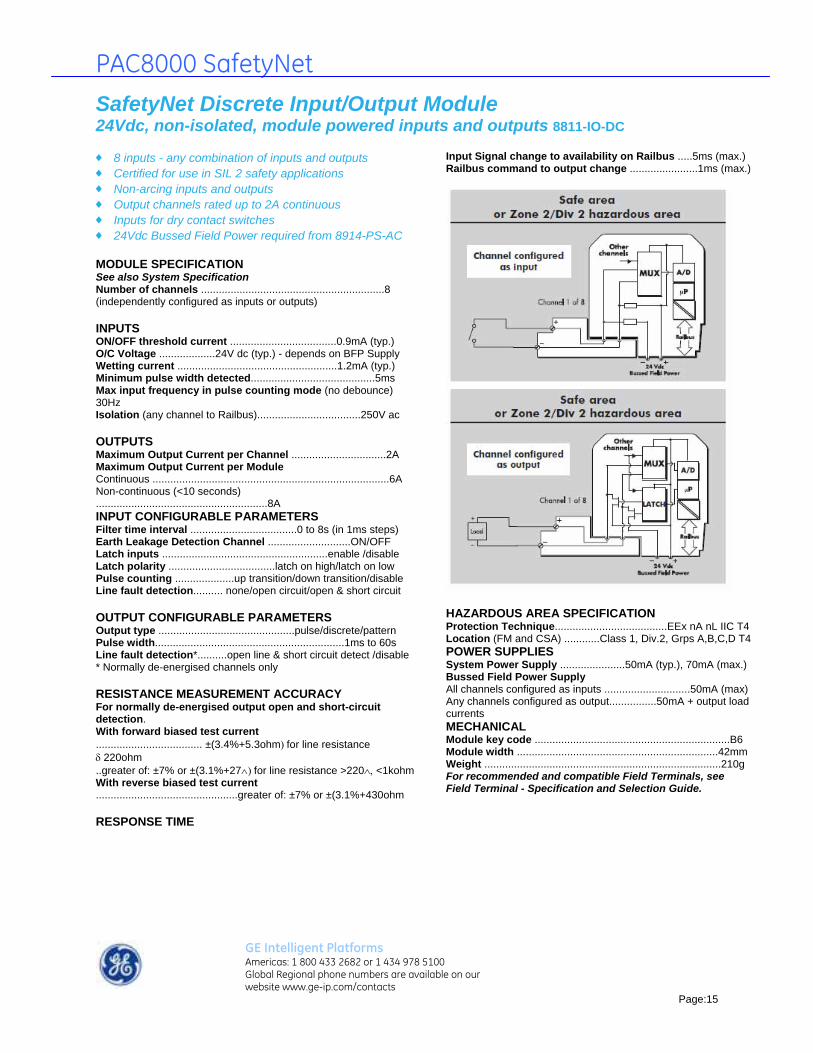
PAC8000 SafetyNet
SafetyNet Discrete Input/Output Module 24Vdc, non-isolated, module powered inputs and outputs 8811-IO-DC ♦ 8 inputs - any combination of inputs and outputs ♦ Certified for use in SIL 2 safety applications ♦ Non-arcing inputs and outputs ♦ Output channels rated up to 2A continuous ♦ Inputs for dry contact switches ♦ 24Vdc Bussed Field Power required from 8914-PS-AC MODULE SPECIFICATION See also System Specification Number of channels ..............................................................8 (independently configured as inputs or outputs) INPUTS ON/OFF threshold current ....................................0.9mA (typ.) O/C Voltage ...................24V dc (typ.) - depends on BFP Supply Wetting current ......................................................1.2mA (typ.) Minimum pulse width detected..........................................5ms Max input frequency in pulse counting mode (no debounce) 30Hz Isolation (any channel to Railbus)...................................250V ac OUTPUTS Maximum Output Current per Channel ................................2A Maximum Output Current per Module Continuous ................................................................................6A Non-continuous (<10 seconds) ..........................................................8A INPUT CONFIGURABLE PARAMETERS Filter time interval ....................................0 to 8s (in 1ms steps) Earth Leakage Detection Channel ............................ON/OFF Latch inputs ........................................................enable /disable Latch polarity ....................................latch on high/latch on low Pulse counting ....................up transition/down transition/disable Line fault detection.......... none/open circuit/open & short circuit OUTPUT CONFIGURABLE PARAMETERS Output type ..............................................pulse/discrete/pattern Pulse width................................................................1ms to 60s Line fault detection*..........open line & short circuit detect /disable * Normally de-energised channels only RESISTANCE MEASUREMENT ACCURACY For normally de-energised output open and short-circuit detection. With forward biased test current .................................... ±(3.4%+5.3ohmfor line resistance 220ohm..greater of: ±7% or ±(3.1%+27for line resistance >220<1kohm With reverse biased test current ................................................greater of: ±7% or ±(3.1%+430ohm RESPONSE TIME
Input Signal change to availability on Railbus .....5ms (max.) Railbus command to output change .......................1ms (max.)
HAZARDOUS AREA SPECIFICATION Protection Technique......................................EEx nA nL IIC T4 Location (FM and CSA) ............Class 1, Div.2, Grps A,B,C,D T4 POWER SUPPLIES System Power Supply ......................50mA (typ.), 70mA (max.) Bussed Field Power Supply All channels configured as inputs .............................50mA (max) Any channels configured as output................50mA + output load currents MECHANICAL Module key code ..................................................................B6 Module width ....................................................................42mm Weight ................................................................................210g For recommended and compatible Field Terminals, see Field Terminal - Specification and Selection Guide.
GE Intelligent Platforms Americas: 1 800 433 2682 or 1 434 978 5100 Global Regional phone numbers are available on our website www.ge-ip.com/contacts
Page:15

PAC8000 SafetyNet
Carriers - overview
General Carriers are the backplanes on to which the PAC8000 SafetyNet and PAC8000 Controllers are mounted. A Controller Carrier is required for each node, then IO Module Carriers, Carrier Extenders and Cables can be added as required – depending on the number of IO Modules needed and their physical distribution within the cabinet or junction box.
Power and communication Carriers distribute “system” power to IO Modules and provide the communications route between Controllers and IO Modules. (Controller power is supplied by direct connections to the Controllers themselves). IO Module Carriers provide connectors through which field power can be supplied (see “Bussed Field Power”). Note: field power to Intrinsically Safe IO is managed differently, see the relevant 2/1 data sheets. Multi-pin connectors at the end of each carrier allow further Carriers to be added– and the “system” power supply and “Railbus” connections to be made. Earthing screens and shields All I/O Module Carriers have their own independent earthing/grounding strip to terminate the screens/shields of field wiring cables. SafetyNet Controller Carrier The SafetyNet Controller Carrier (8751-CANS) is the dedicated Carrier for the SafetyNet System. It can support simplex or redundant SafetyNet Controllers and the Power Supply Monitor (8410-NS-PS). Serial communications Two D-type connectors are provided on the SafetyNet Controller Carrier for connecting to serial devices. These link to Serial Port “1” of Controller A and Controller B. A second pair of D-type connectors is found on the Controllers themselves, to provide connections to Serial Port “2” where redundant serial communication is required. Further details of the serial port connections are given in the data sheet for the SafetyNet Controllers and Carriers. Controller Carriers Two Controller Carriers are available – the standard Controller Carrier and the ELFD Controller Carrier. To comply with the earth leakage fault detection (ELFD) requirements of Fire & Gas application standards, the ELFD Controller Carrier (8751-CA-NS) can be used. A single channel of
an 8811-IO-DC module must be allocated to earth leakage detection to implement this function. SafetyNet applications that do not require ELFD can use the standard Controller Carrier (8750-CA-NS). Change State buttons Two change state buttons are mounted on the SafetyNet Controller Carrier – one for each Controller. The button is used to switch a master to being the standby in a redundant pair, to switch a standby offline and to instruct an offline standby Controller to synchronise itself with the Controller and to enter standby. Terminations for power fail inputs The 8913-PS-AC and 8914-PS-AC power supplies each have an output that indicates the health of the supply. These outputs can be connected to the termination block on the SafetyNet Controller Carrier and are used by the Power Supply Monitor Module to detect failures in any of up to 7 of these external power supplies. Module Carrier SafetyNet Systems use the 8-module Carrier with 64-slot addressing (8709-CA-08) for SafetyNet and standard modules. Up to 8 of these may be used together to provide slots for up to 64 IO Modules. The 4-module Carrier (8710-CA-04) can be used where the application requires four IO Modules or less. This will modify the addressing system and users should contact GE Faniuc when considering this option. Carrier Extenders and Cables To allow for flexibility in cabinet layout, Carrier Extenders are provided which – together with the Extender Cables – are used to connect Carriers mounted on different sections of the cabinet backplane or DIN rail. Carrier Extenders are used in left- and right-hand pairs.
GE Intelligent Platforms Americas: 1 800 433 2682 or 1 434 978 5100 Global Regional phone numbers are available on our website www.ge-ip.com/contacts
Page:16
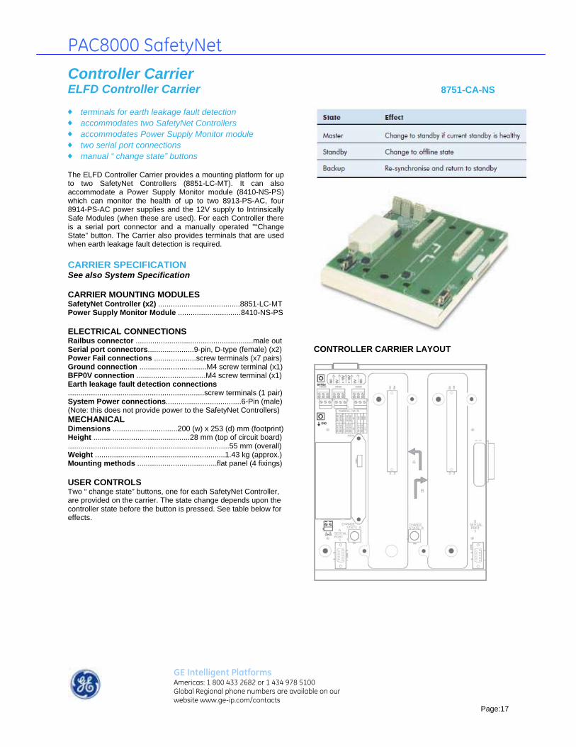
PAC8000 SafetyNet
Controller Carrier ELFD Controller Carrier 8751-CA-NS ♦ terminals for earth leakage fault detection ♦ accommodates two SafetyNet Controllers ♦ accommodates Power Supply Monitor module ♦ two serial port connections ♦ manual “ change state” buttons The ELFD Controller Carrier provides a mounting platform for up to two SafetyNet Controllers (8851-LC-MT). It can also accommodate a Power Supply Monitor module (8410-NS-PS) which can monitor the health of up to two 8913-PS-AC, four 8914-PS-AC power supplies and the 12V supply to Intrinsically Safe Modules (when these are used). For each Controller there is a serial port connector and a manually operated "“Change State” button. The Carrier also provides terminals that are used when earth leakage fault detection is required. CARRIER SPECIFICATION See also System Specification CARRIER MOUNTING MODULES SafetyNet Controller (x2) .......................................8851-LC-MT Power Supply Monitor Module ..............................8410-NS-PS ELECTRICAL CONNECTIONS Railbus connector ........................................................male out Serial port connectors......................9-pin, D-type (female) (x2) Power Fail connections ....................screw terminals (x7 pairs) Ground connection ................................M4 screw terminal (x1) BFP0V connection .................................M4 screw terminal (x1) Earth leakage fault detection connections .................................................................screw terminals (1 pair) System Power connections....................................6-Pin (male) (Note: this does not provide power to the SafetyNet Controllers) MECHANICAL Dimensions ...............................200 (w) x 253 (d) mm (footprint) Height ..............................................28 mm (top of circuit board) .............................................................................55 mm (overall) Weight ..............................................................1.43 kg (approx.) Mounting methods ......................................flat panel (4 fixings) USER CONTROLS Two “ change state” buttons, one for each SafetyNet Controller, are provided on the carrier. The state change depends upon the controller state before the button is pressed. See table below for effects.
CONTROLLER CARRIER LAYOUT
GE Intelligent Platforms Americas: 1 800 433 2682 or 1 434 978 5100 Global Regional phone numbers are available on our website www.ge-ip.com/contacts
Page:17

PAC8000 SafetyNet
Controller Carrier 8751-CA-NS (continued)
EARTH LEAKAGE FAULT DETECTION When earth leakage fault detection is NOT required, a link should be made - as shown below - between the BFP0V and GND connection studs. Note: the BFP0V connection stud must still be connected to Bussed Field Power 0V, marked “-” on the 8914-PS-AC power supply, and the GND connection must still be connected to ground.
When earth leakage fault detection IS required, then the terminals of connector CON12 must be wired to a channel of an 8810-IO-DC module - as shown below - that has been configured for earth leakage. Note: earth leakage fault detection can only operate when BFP0V and all field wiring and field instruments are isolated from ground (GND).
SERIAL PORT CONNECTORS (X2)
SYSTEM POWER SUPPLY CONNECTIONS
Two pairs of System Power supply connections (terminals 2/3 and terminals 4/5) are provided for wiring a redundant pair of 8913-PSAC power supplies. Note: The Controllers do not draw their power from these connections, they are supplied with Controller Power via connections on the Controllers themselves. GND AND BFP0V CONNECTION The GND terminal must always be connected to the main instrument earth or the ‘star-point’ bus-bar. (Note: the 0V of the 8913-PS-AC power supplies is GND). The BFP0V terminal must always be connected to 0V of the 8914-PSAC power supplies.
GE Intelligent Platforms Americas: 1 800 433 2682 or 1 434 978 5100 Global Regional phone numbers are available on our website www.ge-ip.com/contacts
Page:18

PAC8000 SafetyNet
Controller Carrier 8751-CA-NS (continued)
PSU POWER FAIL CONNECTIONS An 8410-NS-PS Node Services Power Supply Monitor Module must be installed on the Controller Carrier to make use of this capability. If an 8410-NS-PS is not being used, then it is not necessary to make any connections to the PSU Power Fail terminals.
Terminal pairs 1, 2, 4 and 5 These terminal pairs are used to monitor the AUX (or power fail) output from up to four 8914-PS-AC power supplies. The upper terminal of each pair is connected directly to the AUX terminal of the 8914-PS-AC that is to be monitored. It is not necessary to connect the lower terminal - as this is internally connected to the BFP0V terminal on the Carrier. If any of the 8914-PS-AC supplies are acting as redundant pairs, then these should be connected to terminal pairs 1 and 2 and/ or terminal pairs 4 and 5. If a pair is unused, a shorting link must be placed between the upper and lower terminals, otherwise the Power Supply Monitor Module will continuously report a fault. Terminal pair 3 The upper terminal of this pair should be connected to the 24V dc supply of the 8914-PS-AC supply monitored by terminal pairs 1 and 2. The lower should be connected to the 24Vdc supply of the 8914- PS-AC monitored by terminal pairs 4 and 5. If a single pair of 8914-PS-AC power supplies is being monitored, then it is only necessary to make single connection to appropriate terminal of pair 3. Terminal pair 6 This terminal pair is unconnected and should not be used.
Terminal pairs 7 and 8 These terminal pairs are used to monitor the AUX (or power fail) output from up to two 8913-PS-AC power supplies. The upper terminal of each pair is connected directly to the AUX terminal of the 8913-PS-AC that is to be monitored. It is not necessary to connect the lower terminal - as this is internally connected to the GND terminal on the Carrier. If a pair is unused, a shorting link must be placed between the upper and lower terminals, otherwise the Power Supply Monitor Module will continuously report a fault. Terminal pair 9 If a Railbus Isolator (8922-RB-IS) is not used in the node, this terminal pair must be fitted with a shorting link to prevent an alarm condition being signalled to the Controller. If a Railbus Isolator is used, internal connections are made to monitor the failure of any power supplies used to provide power for the Intrinsically Safe IO Modules.
GE Intelligent Platforms Americas: 1 800 433 2682 or 1 434 978 5100 Global Regional phone numbers are available on our website www.ge-ip.com/contacts
Page:19

PAC8000 SafetyNet
Module Carrier 8-module Carrier - extended addressing 8709-CA-08
64-slot address bus accepts up to eight SafetyNet and/or standard I/O
modules DIN rail or panel mounting carries control signals and data on Railbus distributes System Power to modules distributes Bussed Field Power to modules isolated earthing bar for cable screens/shields
CARRIER SPECIFICATION See also System Specification ELECTRICAL CONNECTIONS Railbus connectors .....................................female in, male out Cable screens/shield connections...M4 screw terminals (x34) Bussed field power supply connectors.........8-pin male (x2) The two 8-pin connectors provided at the top rear of the carrier connect power supplies for ‘field power’. These supplies are routed through I/O modules that require power for their field circuits. MECHANICAL Dimensions .................................342 (w) x 170 (d) x 22 (h)mm Weight ..............................................................................680g Mounting methods..................................Flat panel or DIN rail DIN-rail types ..........‘Top hat’ 35 x 7.5mm rail or 35 x 15mm rail to EN 50022 ........................................................G-section rail to EN 50035 Note: For applications with up to 4 IO Modules, it is possible to use the 4-module Carrier (8710-CA-04). For further information, contact MTL.
BUSSED FIELD POWER CONNECTOR
CONNECTOR AND TABLE The table above gives the connection details for modules 1 to 4. The second connector provides identical connections for modules 5 to 8.
GE Intelligent Platforms Americas: 1 800 433 2682 or 1 434 978 5100 Global Regional phone numbers are available on our website www.ge-ip.com/contacts
Page:20

PAC8000 SafetyNet
Carrier Extender Left-hand/right-hand 802x-CE-Xh
ensures Railbus and power supply continuity pairs (left & right hand) link separate carrier runs sub-D connectors linked via multi-way cable multi-pin connector to carrier maximum of 3 extender pairs per node 32- and 64-slot address capable
CARRIER SPECIFICATION See also System Specification ELECTRICAL CONNECTIONS Railbus carrier connector 8020-CE-RH ..................................................................female in 8021-CE-LH....................................................................male out Extender cable connector ........................Sub-D, 37-pin female System Power cable connections* ..............screw terminal (x6) System Power cable conductor size..................2.5mm2 (max.) * The six terminals for the System Power connections must be made in addition to connecting the Extender cable. The Terminals on the left- and right- hand extenders indicate which connections need to be made for System Power (HVCC + and HVCC -) and an internal ground connection (SGND). MECHANICAL Dimensions (overall) .................42 (w) x 168 (d) x 37 (h)mm Weight. ..........................................................................135g Mounting method .............................integral DIN-rail fixings DIN rail types ..................‘Top hat’, 35 x 7.5mm or 35 x 15mm to EN 50022 ...........................................................G-section, to EN 50035 PART NUMBERS Carrier Extender, Right-hand 8020-CE-RH Carrier Extender, Left-hand 8021-CE-LH
GE Intelligent Platforms Americas: 1 800 433 2682 or 1 434 978 5100 Global Regional phone numbers are available on our website www.ge-ip.com/contacts
Page:21

PAC8000 SafetyNet
Carrier Extender Cable 0.35m, 0.85m 1.2m 800x-CC-xx ♦ Railbus data extender cables ♦ three lengths - 0.35, 0.85 and 1.2 m ♦ Sub-D cable connectors SPECIFICATION See also System Specification ELECTRICAL CONNECTIONS Extender cable connectors....................Sub-D, 37-pin male (X2) Carrier Extension Cable, 0.35m 8001-CC-35 Carrier Extension Cable, 0.85m 8002-CC-85 Carrier Extension Cable, 1.2m 8003-CC-12
GE Intelligent Platforms Americas: 1 800 433 2682 or 1 434 978 5100 Global Regional phone numbers are available on our website www.ge-ip.com/contacts
Page:22

PAC8000 SafetyNet
Field Terminals – overview
General Field terminals are removable units for terminating wiring from field instruments. Each IO Module combines with a Field Terminal to which the wiring from field instrumentation is connected. Recommended and compatible Field Terminal types are given in the Field Terminal Specification and Selection Guide. They can be selected to optionally include loop disconnection and fusing – eliminating the need for additional terminals and wiring between the Field Terminal and the instrumentation. By wiring directly to the Field Terminal, there is no need for additional terminals or wiring.
8-channel Field Terminals SafetyNet IO Modules use standard 8000 Process I/O 8-channel Field Terminals. Depending on the application, the Field Terminals may be for general purpose, non-arcing or non-incendive field wiring, may incorporate fused disconnects and may be for 2-, 3- or 4-wire transmitters. Fused disconnect The fused disconnect Field Terminals incorporate a 2A fuse that can be partially withdrawn from the Field Terminal to act as a loop disconnect. Tag strip Each Field Terminal is supplied with an integral tag strip, which is hinged to provide access to the wiring terminals and the fuse disconnects. Field Terminal clicks on to Carrier The Field Terminal is easily removed from the Carrier – it is held in place by a sprung latch that can be released without the need for tools. This simplifies connection of the field wiring. The Field Terminal is secured in place by the insertion of the IO Module. Wiring to Field Terminals SafetyNet IO Modules all use 8-channel Field Terminals, to which wiring with a cross section of up to 2.5mm2 can be connected. Each termination point is clearly numbered to simplify recognition of each terminal. The two rows of terminals are offset to allow access to the lower row when wiring is in place.
Keying Rotary keys in the Field Terminal are adjustable to allow insertion of certain modules. Modules that would cause field wiring to be unsafe (in respect of hazardous areas) cannot be inserted. The four types of Field Terminal can be identified from the diagram below
GE Intelligent Platforms Americas: 1 800 433 2682 or 1 434 978 5100 Global Regional phone numbers are available on our website www.ge-ip.com/contacts
Page:23
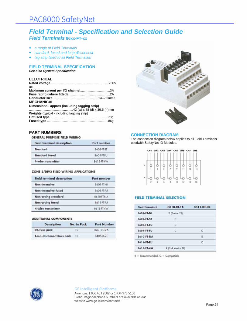
PAC8000 SafetyNet
Field Terminal - Specification and Selection Guide Field Terminals 86xx-FT-xx ♦ a range of Field Terminals ♦ standard, fused and loop-disconnect ♦ tag strip fitted to all Field Terminals FIELD TERMINAL SPECIFICATION See also System Specification ELECTRICAL Rated voltage ................................................................250V ac Maximum current per I/O channel.................................3A Fuse rating (where fitted) ..............................................2A Conductor size ...............................................0.14–2.5mm2
MECHANICAL Dimensions - approx (including tagging strip) .................................................42 (w) x 88 (d) x 39.5 (h)mm Weights (typical - including tagging strip) Unfused type ................................................................78g Fused type ....................................................................86g PART NUMBERS
CONNECTION DIAGRAM The connection diagram below applies to all Field Terminals usedwith SafetyNet IO Modules.
GE Intelligent Platforms Americas: 1 800 433 2682 or 1 434 978 5100 Global Regional phone numbers are available on our website www.ge-ip.com/contacts
Page:24
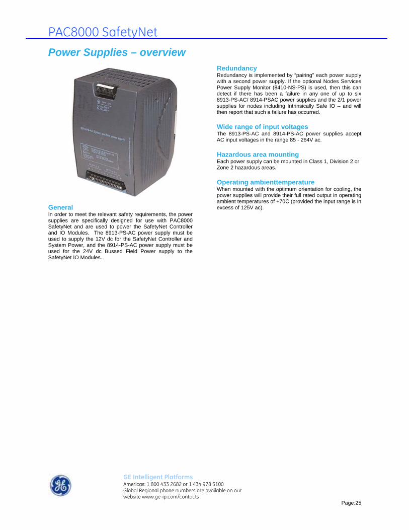
PAC8000 SafetyNet
Power Supplies – overview
General In order to meet the relevant safety requirements, the power supplies are specifically designed for use with PAC8000 SafetyNet and are used to power the SafetyNet Controller and IO Modules. The 8913-PS-AC power supply must be used to supply the 12V dc for the SafetyNet Controller and System Power, and the 8914-PS-AC power supply must be used for the 24V dc Bussed Field Power supply to the SafetyNet IO Modules.
Redundancy Redundancy is implemented by “pairing” each power supply with a second power supply. If the optional Nodes Services Power Supply Monitor (8410-NS-PS) is used, then this can detect if there has been a failure in any one of up to six 8913-PS-AC/ 8914-PSAC power supplies and the 2/1 power supplies for nodes including Intrinsically Safe IO – and will then report that such a failure has occurred. Wide range of input voltages The 8913-PS-AC and 8914-PS-AC power supplies accept AC input voltages in the range 85 - 264V ac. Hazardous area mounting Each power supply can be mounted in Class 1, Division 2 or Zone 2 hazardous areas. Operating ambienttemperature When mounted with the optimum orientation for cooling, the power supplies will provide their full rated output in operating ambient temperatures of +70C (provided the input range is in excess of 125V ac).
GE Intelligent Platforms Americas: 1 800 433 2682 or 1 434 978 5100 Global Regional phone numbers are available on our website www.ge-ip.com/contacts
Page:25

PAC8000 SafetyNet
Power Supply System Power 8913-PS-AC ♦ 12V dc @ 5A System and Controller power ♦ 24V dc @ 5A for powering local instrumentation ♦ 85 – 264V ac input voltage ♦ Zone 2/Div 2 hazardous area mounting ♦ 12V output supports load sharing for redundancy† POWER SUPPLY SPECIFICATION See also System Specification ELECTRICAL CONNECTIONS AC Input connections.........................screw terminals (x3) DC Output connections .....................screw terminals (x8) Power fail signal connection ...............screw terminal (x1) INPUT SPECIFICATION Input voltage.....................................................85–264V ac Input frequency ....................................................47–65Hz Power efficiency ...............................................Up to 87 % Input protection ..internal (6.3A) slow-blow fuse and VDR* OUTPUT SPECIFICATION DC24V output voltage ...............................24.7V dc ± 10% DC12V output voltage ...............................11.95V dc ± 5% DC24V output current...............5A (nominal - see Figure1) DC12V output current .............5A (nominal - see Figure 1) Input-output isolation .........................................2800V dc Hold-up time (at full rated load) ......................15ms (typ.) Thermal protection. .........................reduced output power Supply health indicator. .............................................LED
Figure 1 - DC24V and DC12V output current de-rating † The 24Vdc output does not support load sharing and should only be used for supplying local 24Vdc instrumentation. It should not be
used to supply 24Vdc Bussed Field Power.voltage dependent resistor
POWER-FAIL SIGNALLING - DC12V output only Threshold to trigger "power-fail" signal ............11.33V (max.) ................................................................................10.30V (min.) Power-fail signal output (open collector) Power supply "OK"..............Low impedance to –ve of DC12V output Power supply "failure" ......High impedance to –ve of DC12V output HAZARDOUS AREA SPECIFICATION Protection Technique..............................................EEx nA II T4 Location (FM) ..........................Class 1, Div.2, Grps A,B,C,D T4 Location (CSA) ......................Class 1, Div.2, Grps A,B,C,D T3C MECHANICAL Dimensions ........103 (w) x 138 (h) x 113.6 (d)mm (see Figure 4) Mounting methods ..............35 mm x 7.5 mm T-section DIN rail (see also Accessories overleaf) Weight ................................................................................750g APPROVALS • EN 61204: 1995 Low-voltage power supply devices, d.c. output -Performance characteristics and safety requirements • EN 60950-1: 2002 Safety of information technology equipment • EN 61326: 1997 + A1: 1998 + A2: 2001 Electrical equipment for measurement, control and laboratory use - EMC requirements (Class A equipment) • EN50021: 1999 Electrical apparatus for potentially explosive atmospheres - Type of protection “n”
GE Intelligent Platforms Americas: 1 800 433 2682 or 1 434 978 5100 Global Regional phone numbers are available on our website www.ge-ip.com/contacts
Page:26

PAC8000 SafetyNet
Power Supply System Power 8913-PS-AC continued TERMINAL ASSIGNMENTS Input connector screw terminals
GE Intelligent Platforms Americas: 1 800 433 2682 or 1 434 978 5100 Global Regional phone numbers are available on our website www.ge-ip.com/contacts
Page:27

PAC8000 SafetyNet
Power Supply Bussed Field Power 8914-PS-AC ♦ 24V dc @ 10A for Bussed Field Power ♦ 85 – 264V ac input voltage ♦ Zone 2/Div 2 mounting ♦ supports load sharing for redundancy POWER SUPPLY SPECIFICATION See also System Specification ELECTRICAL CONNECTIONS AC Input connections..........................screw terminals (x3) DC Output connections ......................screw terminals (x8) Power fail signal connection ....................rew terminal (x1) INPUT SPECIFICATIONS Input voltage .....................................................85–264V ac Input frequency......................................................47–65Hz Power efficiency ..................................................up to 87 % Input protection ....internal (6.3A) slow-blow fuse and VDR* OUTPUT SPECIFICATIONS Output ............................................................24V dc ± 10% Output current .........................10A (nominal - see Figure 1) Input-output isolation .........................................2800V DC Hold-up time (at full rated load) ...........................15ms (typ.) Thermal protection ............................reduced output power Supply health indicator .................................................LED
POWER-FAIL SIGNALING Threshold to trigger "power-fail" signal.........23.3V (max.) ............................................................................22.0V (min.) Power-fail signal output (open collector) Power supply "OK" .....................low impedance to ground Power supply "failure" ...............high impedance to ground HAZARDOUS AREA SPECIFICATION Protection Technique........................................EEx nA II T4 Location (FM) .....................Class 1, Div.2, Grps A,B,C,D T4 Location (CSA) ................Class 1, Div.2, Grps A,B,C,D T3C MECHANICAL Dimensions ........103 (w) x 138 (h) x 113.6 (d)mm (see Figure 4) Mounting methods ........35 mm x 7.5 mm T-section DIN rail (see also Accessories overleaf) Weight ...........................................................................750g APPROVALS • EN 61204: 1995 Low-voltage power supply devices, d.c. output - Performance characteristics and safety requirements • EN 60950-1: 2002 Safety of information technology equipment • EN 61326: 1997 + A1: 1998 + A2: 2001 Electrical equipment for measurement, control and laboratory use - EMC requirements (Class A equipment) • EN50021: 1999 Electrical apparatus for potentially explosive atmospheres - Type of protection “n”
GE Intelligent Platforms Americas: 1 800 433 2682 or 1 434 978 5100 Global Regional phone numbers are available on our website www.ge-ip.com/contacts
Page:28

PAC8000 SafetyNet
Power Supply Field Power 8914-PS-AC continued TERMINAL ASSIGNMENTS Input connector screw terminals
Output connector screw terminals
ACCESSORIES Heavy duty DIN rail mounting kit* ......................8413-FK-DN Surface panel mounting kit..................................8414-FK-SU
For high vibration environments
GE Intelligent Platforms Americas: 1 800 433 2682 or 1 434 978 5100 Global Regional phone numbers are available on our website www.ge-ip.com/contacts
Page:29

PAC8000 SafetyNet
Node Services Power Supply Monitor 8410-NS-PS ♦ power supply status monitoring for 8913-PS-AC and 8914-PS-AC power supplies ♦ indicates supply failures to SafetyNet Controller ♦ monitors up to two 8913-PS-AC, four 8914-PS-AC power supplies and the 2/1 supply for nodes including IS IO modules ♦ Zone 2/Div 2 hazardous area mounting ♦ mounts on 8571-CA-NS Carrier The Power Supply Monitor can monitor the health of supplies powering a SafetyNet node and signal the Controller in the event of any one of them failing. The module can receive power supply status signals from up to two 8913-PS-AC and four 8914-PS-AC power supplies. It can also monitor the status of 8920-PS-DC supplies powering intrinsically safe I/O modules. Where power supply redundancy is employed, the module enables failed power supplies to be identified and replaced without interference to the process. The module itself may be removed and replaced in a Zone 2/ Div 2 hazardous area without gas clearance. MODULE SPECIFICATION See also System Specification LED INDICATOR PWR (i.e. System power supply present) HAZARDOUS AREA SPECIFICATION Protection Technique.....................................EEx nL IIC T4 Location (FM and CSA) .....Class 1, Div.2, Grps A,B,C,D T4 POWER SUPPLIES System Power Supply....................5mA (typ.), 10mA (max.) MECHANICAL Mounting method ...........................(captive x2) screw fixing Weight (approx.) ............................................................75g DIMENSIONS Dimensions in mm
GE Intelligent Platforms Americas: 1 800 433 2682 or 1 434 978 5100 Global Regional phone numbers are available on our website www.ge-ip.com/contacts
Page:30

PAC8000 SafetyNet
System Specification System Specification ENVIRONMENTAL Operating Ambient Temperature Optimum orientation* ..........................................-40oC to +70oC Non-optimum orientation......................................-40oC to +50oC Storage ..............................................................-40oC to +85oC Relative Humidity..............................5 to 95% (non-condensing) Ingress protection ............................IP20 to BS EN60529: 1992 Corrosion resistance............Designed to meet ten year service in Class G3 corrosive environment, as per ISA S-71.04: 1985 “Environmental Conditions for Process Measurement and Control Systems: Airborne Contaminants”. * With field terminals vertically above or below the IO Modules. Operating vibration resistance DIN rail mounted* .................................................................... ..................1g (sinusoidal vibration 10 – 500Hz to EN 60068-2-6) ..................1g (random vibration 20 – 500Hz to BS2011: Part 2.1) Surface mounted ...................................................................... ..................5g (sinusoidal vibration 10 – 500Hz to EN 60068-2-6) ..................5g (random vibration 20 – 500Hz to BS2011: Part 2.1) * The ELFD Controller Carrier 8751-CA-NS can only be surface mounted.
GE Intelligent Platforms Americas: 1 800 433 2682 or 1 434 978 5100 Global Regional phone numbers are available on our website www.ge-ip.com/contacts
Page:31
Operating, Storage and Transportation vibration resistance .....30g peak acceleration, with 11ms pulse width (EN 60068-2-27) Storage and Transportation shock resistance ..................................1m drop onto flat concrete (EN 60068-2-32) MECHANICAL DIN-rail types ..............................................’Top hat’, 35 x 7.5mm to EN 50022 ..............................................’Top hat’, 35 x 15 mm to EN 50022 ................................................................G-section, to EN 50035 ISOLATION Between SafetyNet channels ............................................none Channel (any) to railbus ......................................250V ac rms NODE SIZE LIMITATIONS Maximum physical length of railbus* ............................6.8m Maximum number of extender cables ..................................3 Maximum number of IO Modules........................................64 Maximum number of SafetyNet nodes ............................249
overall including backplanes and extender cables HAZARDOUS AREA APPROVAL SafetyNet node location ..................................................................................Safe area or ....................................................Zone 2, IIC, T4 hazardous area ........................Class 1, Div 2, Groups A-D T4* hazardous location * 8913-PS-AC and 8914-PS-AC power supplies T3C Field equipment and wiring location ..................................................................................Safe area or ..........................................................Zone 2, IIC hazardous area ..............................Class 1, Div 2, Groups A-D hazardous location (Temperature classification will be determined by the field apparatus) Applicable hazardous area standards: Factory Mutual Research Co., 3611: 2004. “Non-incendive Electrical Equipment for use in Class I and II, Division 2, and Class III Divisions 1 and 2, Hazardous (Classified) Locations”. CSA C22.2 No 213-M1987, Reaffirmed 2004. “Nonincendive Electrical Equipment for Use in Class I, Division 2 Hazardous Locations”. EN 60079-0:2004 “Electrical apparatus for explosive gas atmospheres. Part 0: General Requirements”.
EN 60079-15: 2005 “Electrical apparatus for explosive gas atmospheres. Part 15: Construction, test and marking of type of protection ‘n’ electrical apparatus”. ELECTRICAL STANDARDS AND APPROVALS Applicable EMC standards EN 61326-1: 2005. “Electrical equipment for measurement, control and laboratory use – EMC requirements. Part 1: General requirements”. Applicable Electrical Safety standards IEC 61131-2: 2003. “Programmable controllers - Part 2: Equipment requirements and tests”. SAFETY APPROVALS Applicable Functional safety standards IEC 61508:2000. “Functional Safety of Electrical/Electronic/Programmable Electronic Safety-related Systems” IEC 61511:2004. “Functional Safety - Safety Instrumented Systems for the Process Sector”.
System Specification System Specification CABLE PARAMETERS FOR NON-INCENDIVE FIELD WIRING


GEIntelligent Platforms
The PAC8000 Controllers are the latest addition to GE Intelligent Platforms’ family of controllers.
The PAC8000 Controllers are designed specifi-cally to provide a solution where a controller needs to be field mounted in the extreme envi-ronments found in process applications.
PAC8000 Controllers, with their rugged and redundancy characteristics will help you improve your operational performance and productivity for a sustainable advantage.
Powerful Open Controllers The PAC8000 Controllers consist of a Process Controller, Logic Controller, and RTU Controller with DNP3 Ethernet. These controllers provide a tight control loop response, generating a control output in response to input data within 100 ms.
Ethernet Bus Interface Modules (EBIM) provide for communications between controllers and remote I/O.
Environmental & Hazardous Area Operation PAC8000 Controllers can go where other con-trollers cannot. They can be field mounted and subjected to the following:
• –40°Cto+70°Coperatingrange• ISALevelG3corrosion• 30Gshocksand5Gvibration• OperationinClassI,Division2andZone2
hazardous areas with I/O module field wiring extendingintoDivision1andZone1/0areas
Peer-to-Peer Communications PAC8000 Controllers communicate directly with each other and share data on a peer-to-peer basis without having to route data through a centralized database or controller.
• Criticalinformationcanbesharedefficientlybetween controllers
HART Support PAC8000 Controllers can pass HART informa-tion from smart field devices to a separate PC workstationrunningassetmanagementsoft-ware applications to remotely manage smart instrument configuration and calibration.
• HARTpassthroughfromsmartfielddevices• HARTdataanddiagnosticscanalsobe
used directly in control applications• Reduces:
- commissioning time - process downtime - loop maintenance costs using - field device diagnostics
PAC8000 ControllersController Redundancy Application reliability is improved with controller redundancy.
• Redundantcontrollersinsamecarrierforincreased reliability and small footprint
• Redundantcontrollersoperateinparallel,checkingstatusmultipletimesthroughtheprocessingloop,enablingthebackupcon-troller to continuously monitor the health of the master controller, thereby assuring a rapid and bumpless change over, as required
• Aredundantcontrollerisalsocapableofreceiving a firmware upgrade in the field
Network Redundancy Networkredundancyhelpsassurestableandconsistent communications.
• ThecontrollerhastwohighspeedEthernetports that use Fault Tolerant Ethernet to provide redundant communications
• Eachportcanbeconnectedtoanindepen-dent LAN which is continuously monitored for its integrity. If the primary port detects anetworkfailure,trafficisimmediatelyswitched to the other LAN to maintain full communications
Engineering Tools TheWorkbenchprovidesanintegratedproj-ect development environment coupled with development modules and tools and a com-prehensive set of diagnostic utilities.
• Thisdevelopmentenvironmentcentralizesproject engineering including I/O (Instrument Index) and control strategy configuration
• Acomprehensivefunctionblockdiagramlibrary for addressing advanced process control requirements is provided for pro-cess, logic & hybrid controllers
• SupportsallfiveIEC61131-3program-ming languages (Ladder Logic Diagram, StructuredText,InstructionList,SequentialFunctionChartandFunctionBlockDia-gram) plus Flow Chart
6 PAC8000 Process Controller
6 PAC8000 Logic Controller
6 PAC8000 Hybrid Controller
6 PAC8000 RTU Controller

11.10GFA-1754
GE Intelligent Platforms Contact Information
Americas: 1 800 433 2682 or 1 434 978 5100 Global regional phone numbers are listed by location on our web site at www.ge-ip.com/contact
www.ge-ip.com
©2010GEIntelligentPlatforms,Inc.Allrightsreserved.All other brands or names are property of their respective holders.Specificationsaresubjecttochangewithoutnotice.
PAC8000 Controllers
Ordering Information
Controllers and CarriersPart Number Description Part Number Description
8410-NS-PS Nodeservicespowersupplymonitor 8521-LC-MT LogicController8521-EB-MT EthernetBIM 8521-RT-DE RTUController8521-HC-MT HybridController 8750-CA-NS Carrier,simplexorredundant,powermonitoring
8000 General Purpose I/O *Part Number Description Part Number Description
8101-HI-TX 8-channelAI,4-20mAwithHART 8116-DO-AC 8-channelDO,20-250Vacnon-isolated,modulepowered8102-HO-IP 8-channelAO,withHARTfor4-20mA 8117-DO-DC 8-channelDO,2-60Vdcisolated,unpowered8103-AI-TX 8-channelAI,4-20mA 8118-DO-AC 8-channelDO,20-250Vacisolated,unpowered8104-AO-IP 8-channelAO,4-20mA 8119-VI-05 8-channelVoltageInput,1-5Vdc8105-TI-TC 4-channelTHC/mVinput 8121-DI-DC 16-channelDI,24Vdcnon-isolated,modulepowered8106-TI-RT 4-channelRTDinput 8122-DI-DC 16-channelDI,24Vdcisolated,sinking8109-DI-DC 8-channelDI,24Vdcisolated,sinking 8123-PI-QU 2-channelPulseQuadratureInput8110-DI-DC 8-channelDI,24Vdcnon-isolated,modulepowered 8125-DI-DC 32-channelDI,non-isolated,module-powered 8111-DI-AC 8-channelDI,115Vacisolated,sinking 8127-DI-SE 32-channelSOEmodule8112-DI-AC 8-channelDI,115Vacnon-isolated,modulepowered 8129-IO-DC 8-channelsupervisedDI8113-DI-AC 8-channelDI,230Vacisolated,sinking 8132-AI-UN 8-channelIsolatedUniversalAI8114-DI-AC 8-channelDI,230Vacnon-isolated,modulepowered 8133-HI-TX 8-channelsupervisedAIwithHART8115-DO-DC 8-channelDO,2-60Vdcnon-isolated,modulepowered
Field Terminals and AccessoriesPart Number Description Part Number Description
8601-FT-NI Fieldterminal,non-incendive(Div2) 8610-FT-NA Fieldterminal,non-arcing(Div2)8602-FT-ST Fieldterminal,standard 8611-FT-FU Fieldterminal,non-arcing,fused(Div2)8603-FT-FU Fieldterminal,non-incendive,fused(Div2) 8615-FT-4W Fieldterminal,4wire(currentsinking)8604-FT-FU Fieldterminal,fused 8617-FT-NI FieldTerminal,non-incendive,for16chDI8605-FT-TC Fieldterminal,thermocouple 8618-FT-MT 16-pinMassTerminationAssembly(Div2)8606-FT-RT Fieldterminal,RTD 8619-FT-MT 44-pinMassTerminationAssembly(Div2)8607-FT-TC Fieldterminal,8-channelwithT/C 8650-FT-PX 32-channelPX/SwitchFTAfor8125/78608-FT-NI Fieldterminal,8-channel,non-incendive
8000 I/O CarriersPart Number Description Part Number Description
8707-CA-08 8modulecarrier 8710-CA-04 4modulecarrier8709-CA-08 8modulecarrier,64-addresssystem
8000 I/O Carrier CablesPart Number Description Part Number Description
8020-CE-RH Carrierextender,righthand 8080-FC-10 16-pincablefor8618(1m)8021-CE-LH Carrierextender,lefthand 8081-FC-20 16-pincablefor8618(2m)8041-CC-35 Carrierextensioncable,0.35m 8082-FC-30 16-pincablefor8618(3m)8042-CC-85 Carrierextensioncable,0.85m 8085-FC-10 20+24pincablesfor8619(1m)8043-CC-12 Carrierextensioncable,1.2m 8086-FC-20 20+24pincablesfor8619(2m)8044-CC-20 Carrierextensioncable,2m 8087-FC-30 20+24pincablesfor8619(3m)
8000 I/O Power Supplies and ComponentsPart Number Description Part Number Description
8413-FK-DN 8913/4PSDINRailMountingKit 8914-PS-AC 10A24VDCA/CInputP/S8414-FK-SU 8913/4PSSurfaceMountingKit BQ2320-9R-EX 24to12VDCVoltageConverter8913-PS-AC 5A12VDC&5A24VDCA/CInputP/S
*Note: Intrinsically Safe I/O also available.

GE Intelligent Platforms
PAC8000 Process Controller 8521-PC-MT Open control platform The PAC8000 Process Controller executes your control strategies and manages all control activities for the I/O modules. It also manages communications on the control network. The controller has a tight control loop response, rapidly providing a control output in response to input data. The controller incorporates a rigorous redundancy model, fieldbus integration for connecting to HART® and a fault tolerant Ethernet implementation to deliver reliable system operation in your application. Applications The PAC8000 Process Controller, with its process oriented function block programming, is designed to satisfy the process automation market, which includes industries like: power generation and electrical distribution, food and beverage, chemicals and petrochemicals, water and waste water, oil and gas pipelines, cement and pulp and paper. Benefits Cost saving solution The PAC8000 Process Controller takes advantage of Windows 2000 & XP based object-oriented technology, graphical user interfaces and easy to learn software solutions to reduce process control system life cycle expenditures by 30–40%. One Step Engineering The PAC8000 Process Controller eliminates expensive, laborious, and sometimes error prone manual engineering work typically required during control projects. Manual generation of design documents, bill of materials and wiring diagrams is eliminated. Similarly, repetition of advanced control strategies is no longer necessary; eliminating re-entry of program information and
significantly reducing system configuration time. Function block based Workbench software (part number 8459-PC-MT) is used to configure the control strategy. When your application is completed, it can also generate an export table that is used to create the operator interface database for popular HMI packages. On-line changes PAC8000 Process Controllers allow on-line configuration changes during testing, start-up, and maintenance phases. This significantly accelerates system start-up and reduces operation downtime. It is easy to configure the control project in a single step and automatically generate the point database. Comprehensive Self-Documentation PAC8000 Process Controllers automatically generate as-built system documentation including I/O configuration reports, cross reference analysis, bill of materials, instrument index, system start-up, maintenance information and wiring diagrams. Since the drawings are used to develop the control strategy, they are continuously maintained, as the final control strategy is adjusted to an optimum level. You no longer need to update the documentation at the end of the project to assure that it reflects the actual plant configuration; the system drawings are automatically kept current providing you with significant time savings. Built-in diagnostics Extended diagnostics are available to provide module and channel status information, including high and low alarm, open circuit detection and line fault detection at the device level and "fail-safe" perform level.
PAC8000 Strategy Builder Logic diagrams are developed using the PAC8000 Strategy Builder. The control strategy is built by selecting the appropriate function blocks, assigning symbolic tags and then connecting the blocks with analog or digital lines using standard drawing forms and commands. SAMA style drawings define all the function and parameters that form a process loop. Function block choices include: manual/ auto station, function-generators, pulse-controller, sequencers, bumpless transfers, PID, etc. Complex control strategies are available, including such as feed forward, cascade and multi-variable control are also supported. Template diagrams can be created and reuses within the current project or another future project. Advanced control strategies PAC8000 Process Control algorithms provide the logic and analytical functions for complex control strategies such as feed forward, cascade and multi-variable control. Adaptive tuning functions for PID control is supported. Two and three state device drivers provide the functionality for motor and valve operations with alarms, remote operation and interlocks. Sequential step functions with interlocks and first out functionality are easily configured. Reduced cable costs Instrumentation cable pairs terminate locally instead of being run across the plant to the control room. Heavy, expensive sensor cables are replaced by the LAN cable. High system availability - easy maintenance Maximize up-time through use of redundant PAC8000 controllers, power supplies and network connections. “Hot swap” modules without affecting system operation or re-configuring even in hazardous areas.
The PAC8000 Process Controller is a rugged, field-mountable control platform intended for those process applications that may have utilized programmable controllers (PLCs) because of their ability to scale to fit smaller applications. Designed for process applications, the PAC8000 Process Controller provides you with an effective alternative to PLC solutions. Combined with the 8000 Process I/OTM system components, it offers cost savings over control room mounted systems as well as flexible system design and high system availability. A PAC8000 Process Control system can utilize any off-the-shelf HMI package.

PAC8000 Process Controller 8521-PC-MT powerful, robust controller for advanced control strategies PAC8000 Strategy Builder for process control applications redundancy with bumpless transfer dual-redundant high-speed Ethernet connections field mountable in harsh process environments peer to peer communications between controllers on-line configuration and reconfiguration HART® pass-through of process and status variables Integrated general-purpose and IS signals
Controller redundancy Redundant controllers can be used for critical control applications. The redundant controller pair operates in parallel, checking status multiple times through the processing loop enabling the backup controller to continuously monitor the health of the master controller, assuring a rapid and bumpless transfer to the standby controller. Network redundancy In addition to controller redundancy, the PAC8000 Process Controller has two high-speed Ethernet ports to provide security of communication. Each port can be connected to an independent LAN which is continuously monitored for its integrity. If the primary port detects a network failure, traffic is immediately switched to the other LAN to maintain full communication. Executable control programs The control programs are held in non-volatile memory to enable them to be restored automatically after power cycling of the controller. The use of a redundant controller also enables a new control program to be downloaded to the standby unit while the process continues. When the download has been completed and verified, the standby can be switched to master status to employ the new program. Remote Modbus Devices The PAC8000 Process Controller communicates via Modbus TCP over Ethernet and can operate in either Modbus Master or Modbus Slave mode to communicate with remote Modbus devices. Each controller also has 2 serial ports that can be configured as a Modbus Master to control and obtain information from Modbus Slaves and other serial devices, such as weigh scales, barcode readers, etc. The serial ports can also be configured as a Modbus Slave, accepting write commands from Modbus Master
devices and providing information on its data registers. Failsafe and automatic cold start In the event of complete loss of communication the controller will adopt a user-defined failsafe mode and similarly instruct the I/O to take up user-defined failsafe values. In the event of power loss the PAC8000 Process Controller will perform a cold restart which restores the program(s) and assumes a predefined status. Peer to peer communications PAC8000 Process Controller can communicate with each other on a peer-to-peer basis, enabling controllers to share data with each other. This capability ensures that critical information can be efficiently shared between controllers instead of requiring data to be passed to each controller from the control room. I/O module configuration The PAC8000 Process Controller receives full details of all the I/O modules under its control and stores the information in non-volatile memory. At start-up the controller downloads to the modules their configuration details, which also include the failsafe states they should adopt in the event of communication failure. Firmware updates In keeping with its ability to maintain operations on a continuous basis, a redundant PAC8000 Process Controller is also capable of receiving a firmware upgrade. In a manner similar to that used for strategy updates, a controller can receive an update to its firmware while in the field. When the upgrade has been confirmed as successful, the controller can be returned to full operation as a master or as a protective standby. HART® pass-through The PAC8000 Process Controller has the ability to pass smart HART® information
from field devices to a separate PC workstation, which allows you to readily interface to asset management software applications, to remotely manage the HART® information contained in your HART®-based field instruments. The PAC8000 Process Controller works with a variety of asset management packages, including Applied System Technologies' Cornerstone software or Emerson's Asset Management Solutions. Environmental stability Like all of the 8000 series equipment, the PAC8000 Process Controller is designed for use in harsh environments. It operates over a temperature range of –40°C to +70°C and is resistant to shock, vibration and corrosive environments. Hazardous area operation The PAC8000 Process Controller is designed also to operate in Class I, Division 2 and Zone 2 hazardous areas and can control I/O modules that have field wiring extending into the more hazardous Division 1, Zone 1 and Zone 0 areas. Grows as your needs grow The system is scalable to your needs. You can add modular I/O to your system as your needs increase. Redundant controllers can be added without the need to power off your system - the backup controller powers up automatically and is seamlessly brought online. Maximum number of nodes Multiple PAC8000 controller nodes can reside on the same network allowing peer-to-peer communications, as explained above. However, too many nodes can degrade performance, so GE Intelligent Platforms recommends placing no more than 25 nodes on the same subnet of a network.

PAC8000 Process Controller 8521-PC-MT 8000 Process I/O™ hardware Overview 8000 is a completely modular I/O solution for both general purpose and hazardous area applications. It is based on a carrier system that supports a range of modules and offers a wide variety of I/O functions, including AC mains and intrinsic safety signals, even within the same node. I/O Modules I/O modules transfer signals to and from field instruments. Input modules
receive signals from transmitters and sensors and convert them into a digital form for presentation to the Controller. Output modules
receive commands from the Controller and transfer them to actuators. A wide range of modules is available, including types for low-level instrumentation, AC mains and intrinsically safe signals, I/O modules typically have 4, 8 or 16 field channels. Field terminals Field terminals provide the interface between the I/O modules and the field wiring. They include fusing and loop-disconnect as options. A mechanical keying system prevents an I/O module from being connected to the wrong type of field terminal. Field terminals mount onto the module carrier, one to each I/O module. They are clamped firmly by the I/O module to form an electrical and mechanical assembly of high integrity. They may be replaced in service without removing carriers or disturbing the operation of other modules. Carriers Carriers form 8000's physical and electrical backbone by providing a mounting to support and interconnect the controller, power supplies, I/O modules and field terminals, and carry the address, data and power lines of the internal Railbus. They provide termination points for the LAN and to the I/O modules. I/O module carriers
are available to support four or eight I/O modules.
System power supplies System power supplies are available for the node to convert local AC or DC supplies to power the node or pro-vide field power for I/O modules. 8000's innovative Bussed Field Power scheme for distributing field power avoids complex wiring at the field terminal and minimizes the carrier wiring. 'HART-ability' The use of 'smart' instruments on process plants is growing but this investment is not always fully exploited. Whether it is for a new installation, or the upgrade of an existing one, GE Intelligent Platforms has solutions that provide the connections between the HART field instruments, the control systems and the process automation maintenance software. Specifically, the 8000 Process I/O system has been designed to be transparent to HART signals, thus allowing the host control software and any HART field instruments to communicate directly with each other. In addition, 8000's HART connection system provides on-line access from a PC to the HART field devices for monitoring device performance. HART devices may be selected for regular status monitoring and alerts can be issued if the status changes. The benefits from this approach are: reduced commissioning time and
cost reduced process downtime through
status monitoring power loop maintenance costs by
using field device diagnostics. 8000 in your system Each PAC8000 node can address up to 64 I/O modules which, depending upon the number of channels per module, can pro-
vide up to 1024 I/O points at a single node! A node can consist of a mixture of analog and discrete modules and this gives maximum flexibility to the system designer. Full HART pass-through is provided - the 8000 appears "transparent", allowing the inquiring "agent" to access the HART capabilities of field instruments. GE Intelligent Platforms recommends placing no more than 25 nodes on the subnet of a network. Redundancy options 8000 has been designed to increase availability and minimize downtime. Redundant controllers, LAN Channels and power supplies can be specified as options to increase system availability. Possible down-time is further reduced by ensuring that the system components using active circuitry can be removed and replaced quickly and easily. Even the field terminals can be replaced without interrupting the operation of adjacent I/O modules. Carriers have no active circuitry and are unlikely to need replacement. Hazardous area applications The 8000 is a truly field mountable system even in areas where flammable gases are present. It is available in versions to suit different area classification schemes:
a) Equipment and field wiring located in general purpose areas, Class 1, Division 2 hazardous locations or Zone 2 hazardous areas.
b) Equipment mounted in general purpose areas, Class 1, Division 2 hazardous locations or Zone 2 hazardous areas, with field wiring located in Division 1 hazardous locations or Zone 0 hazardous areas.
Time stamping data PAC8000 Controllers can be time synchronized to within approximately 10ms or 2ms if an external SNTP clock is used. Controllers can be configured to time stamp a change to any data field with a time stamping resolution equal to the execution cycle length (typically in the range 50ms to 250ms). Controllers can record approximately 8000 events (7800 worst case) in this way, before the data is over-written by new data. If more accurate time stamping is required, the dedicated Sequence of Events (SOE) module may be used. This can provide a channel-to-channel time stamp accuracy of 0.5ms, within the same module (based on a per-channel resolution of 0.25ms).

PAC8000 Process Controller 8521-PC-MT A control node Many industry applications do not present an explosion risk from gas or dust hazards. In others, the environment may be classified as a Zone 2 or Division 2 hazardous area, where flammable material is expected to occur only in abnormal conditions. For both of these the 2/2 system provides effective distributed I/O for process control. 8000 supports a full range of I/O module types covering inputs and outputs for both analog and discrete circuits. The node can be mounted out on the plant in a suitable enclosure that is capable of providing protection against the environment. The diagram shows a node containing the basic components: one (or two) PAC8000 Logic Controllers, I/O modules on their carriers linked by carrier-extenders and an extension cable. 8000 with intrinsic safety field wiring The 8000 Process I/O System is also capable of supporting I/O modules with intrinsic safety (IS) field wiring, for connection to certified or 'simple apparatus' field devices in Division 1 or Zone 0 hazardous areas. A range of I/O module types with IS field circuits for industry-standard DI, DO, AI, AO and pulse applications is supported. Integrated power supplies Power for IS I/O modules is derived from integrated, modular power supply units. Each power unit is capable of supplying between eight and twenty I/O modules, depending on the I/O type and mix. Optional power supply redundancy is supported by means of an additional, redundant supply unit connected in an 'n+1' arrangement. In applications with mixed IS and non-IS field wiring, the full facilities of the 'Bussed Field Power' regime are retained for the non-IS part of the system. In nodes populated only with IS I/O modules, a separate system power supply module provides power for the Bus Interface Module and 'node services'. Redundancy of this supply is also supported. PAC8000 The mission of GE Intelligent Platforms is to design, manufacture and distribute modular, open hardware and software technology-based components for use in the most demanding real-time system applications. These field-proven components can be “snapped” together to create sophisticated control systems. ORDERING INFORMATION Controller Order using the following part number: PAC8000 Process Controller.........................................................8521-PC-MT (This Controller includes PAC8000 Process control software)
Workbench Workbench software is required to configure the control strategy for each controller. PAC8000 Process Workbench.....................................................8459-PC-MT (Will configure PAC8000 Process controllers and PAC8000 EBIM)
CONTROLLER SPECIFICATION See System Specification for other parameters Modbus™ is a trademark of Schneider Automation Inc HART® is a registered trademark of the HART Communication Foundation
LAN INTERFACE Transmission medium............................100BaseTX or 10BaseT Ethernet Transmission protocol.......................Modbus over High Speed Ethernet Transmission rates....................................................................10 - 100 Mbits/s LAN connector type (x2) ..................................................................RJ45 (8-pin) LAN Insulation (Dielectric withstand) ...................................................1500 V Action on software malfunction .............................. Halt CPU / Reset CPU Max. nodes on a subnet of a network.......................................................... 25 SERIAL INTERFACES (COM 1 & COM 2) Transmission rates............................................... 1.2 – 115.2 kbits/s (async.) Transmission standard ...................................................... RS485 half-duplex COM 1 connector (on carrier) ..........................9-pin D-type connector (F) COM 2 connector (on controller) ..................9-pin D-type connector (M) POWER SUPPLIES Voltage ............................................................................................10.9 – 12.6 V dc Current ...................................................................................................... 0.4 A ( typ.) .....................................................................................................................0.5 A (max.) HAZARDOUS AREA APPROVALS Location of controller............. Zone 2, IIC T5 hazardous area .........or Class 1, Div 2, Groups A, B, C, D T5 hazardous location Applicable standards: Factory Mutual Research Co., Class No. 3611 for Class I,
Division 2, Groups A, B, C, D hazardous locations CSA Std C22.2 No. 213 for Class 1, Division 2, Groups A, B, C, D
hazardous locations ATEX Category 3 (for Zone 2 installation) to EN50021:1999
protection type ‘n’ UL 61010-1 “Safety Requirements for Electrical Equipment for
Measurement, Control, and Laboratory Use; Part 1: General Requirements, 2nd Edition
MECHANICAL Module dimensions .........................................69 (w) x 232 (d) x 138 (h) mm Weight (approx.) ........................................................................................... 1.35 kg
GE Intelligent Platforms Information Center Headquarters: 1 800 GE 32682 1 800 322 2616 1 434 978 5100 © 2008 GE Intelligent Platforms, Inc. All Rights Reserved. *Trademark of GE Intelligent Platforms, Inc. All other brand names or names are property of their respective holders.
Additional Resources For more information, please visit the GE Intelligent Platforms website at: www.ge-ip.com

GE Intelligent Platforms
PAC8000 Hybrid Controller 8521-HC-MT Overview PAC8000 Hybrid Control provides a fully integrated solution for process control, logic automation and strategy development. PAC8000 Hybrid Control provides a process engineer with the tools to design, implement, document, and maintain a process control system using advanced control strategies. PAC8000 Hybrid Control consists of a number of open system components. The PAC8000 Hybrid Workbench is
an integrated development environment that centralizes and coordinates project data including instrument indexes, control strategies (process and logic) and project management. It configures the control logic and generates an export database to create the operator (HMI) database.
A rugged field-mountable Control Platform, consisting of the PAC8000 Hybrid controller (8521-HC-MT) and the 8000 Process I/O system.
Applications PAC8000 Hybrid Control is designed to satisfy the process automation market, which includes industries like: power generation and electrical distribution, food and beverage, chemicals and petrochemicals, water and waste water, oil and gas pipelines, cement and pulp and paper. PAC8000 Hybrid Control, with its simultaneous support of both process and logic automation strategies, is an ideal solution for process applications that may also
require some sequential logic control in a process environment. PAC8000 Process Control PAC8000 Process Control is an open, easy-to-use process control engineering and management solution that delivers comprehensive, distributed control system functionality. PAC8000 Process Control is a fully integrated advanced process control and instrument engineering system offering configuration tools, modeling, simulation, troubleshooting utilities, project drawing management and self-documentation. It is a robust solution that provides the flexibility to configure control systems ranging from a few loops to thousands of points. A flexible, scalable design allows cost effective system expansion. In addition, the system's extensive use of industry standards simplifies integration with other applications. PAC8000 Logic Control The PAC8000 Hybrid Workbench is your complete tool kit for creating IEC 61131-3 programs. The Workbench fully supports the five IEC 61131-3 automation languages - Ladder Diagram (LD), Sequential Function Chart (SFC), Function Block Diagram (FBD), Structured Text (ST), Instruction List (IL) - plus Flow Chart and is used to develop, download, simulate, debug, monitor, and edit application programs. PAC8000 Logic Control lets you mix programming languages in the same project. Its true Windows interface will guide you through development of your project. The Workbench Simulator will test your programs before startup. Then use the Workbench to dynamically
view programs as they run in real-time and make changes on-the-fly. PAC8000 Control Platform The PAC8000 controller executes your control strategies and manages all control activities for the I/O modules. It also manages communications on the control network. The controller provides a tight control loop response, providing a control output in response to input data within 100 ms. The controller incorporates a rigorous redundancy model, fieldbus integration for connecting to HART® and a Fault Tolerant Ethernet implementation to deliver reliable system operation in your application. The controller can concurrently execute both PAC8000 Process Control strategies for process control and an IEC 61131-3 control language for logic control applications. PAC8000 Remote I/O Remote I/O can be used with PAC8000 controllers, allowing you to further distribute control capability in your plant. Connected with an Ethernet Bus Interface Module (EBIM), Remote I/O communicates with the controller using high-speed peer-to-peer communications. The Workbench configures both Remote I/O and local I/O in the same way, providing a fully integrated Remote I/O solution. The PAC8000 Control Platform and Remote I/O are built for harsh process applications, operating over the industrial –40°C to +70°C temperature range that is typically associated with field transmitters and meeting ISA's stringent G3 corrosion resistance requirements. The Controller and I/O solution can both be mounted directly in Division 2 /Zone 2 hazardous areas and, when required, can provide a cost effective intrinsic safety solution.

PAC8000 Hybrid Controller 8521-HC-MT
Because the system can be mounted in the field, it can also provide extensive cost savings by eliminating the need to wire all sensors back to a central controller. With the PAC8000 Controller and its I/O mounted in the field, the only wiring back to a control room is the high-speed control network. Redundant PAC8000 Controllers PAC8000 Hybrid Control offers extensive redundancy choices to provide you with several options to assure that your system provides the required system availability, including: Redundant controllers Control networks System power supplies
Peer to Peer Communications PAC8000 Controllers can communicate with each other on a peer-to-peer basis, enabling controllers to share data with each other. This capability assures that critical information can be efficiently shared between controllers instead of requiring data to be passed to each controller from the control room. Benefits Cost saving solution PAC8000 Hybrid Control takes advantage of Windows 2000 & XP based object-oriented technology, graphical user interfaces and easy to learn software solutions to reduce process control system life cycle expenditures by 30–40%. One Step Engineering PAC8000 Hybrid Control eliminates expensive, laborious, and sometimes
error prone during control projects. Manual generation of design documents, bill of materials and wiring diagrams is eliminated. Similarly, repetition of advanced control strategies is no longer necessary; eliminating re-entry of program information and significantly reducing system configuration time. The Workbench configures the control logic and generates and export table that is used to create the operator interface database for many popular HMI packages. On-line changes PAC8000 Hybrid allows on-line configuration changes during testing, start-up, and maintenance phases. This significantly accelerates system start-up and reduces operation downtime. It is easy to configure the control project in a single step and automatically generate the point database. Comprehensive Self-Documentation PAC8000 Hybrid Control automatically generates as-built system documentation including I/O configuration reports, cross reference analysis, bill of materials, instrument index, system start-up, maintenance information and wiring diagrams. Since the drawings are used to develop the control strategy, they are continuously maintained, as the final control strategy is adjusted to an optimum level. You no longer need to update the documentation at the end of the project to assure that it reflects the actual plant configuration; the system drawings are automatically kept current, providing you with significant time savings.
Bussed Field Power This is a unique, flexible feature that allows field circuits to be powered with a minimum of wiring and termination effort. A single power supply connection to the module carrier can supply two I/O modules (up to 32 channels), without the need for "daisy-chaining" at the field terminals. Built-in diagnostics Extended diagnostics are available to pro-vide module and channel status information, including high and low alarm, open circuit detection and line fault detection at the device level and "fail-safe" performance at the module level. Reduced cable costs Instrumentation cable pairs terminate locally instead of being run across the plant to the control room. Heavy, expensive sensor cables are replaced by the LAN cable. Reduced termination costs Field wiring goes directly to the I/O terminals in the local field enclosure. This means there is no additional cross wiring to marshalling panels. Flexible system design Combine analog and logic modules for maximum flexibility and use of space. High system availability - easy maintenance Maximize up-time through use of redundant PAC8000 controllers, power supplies and network connections. “Hot swap” modules without affecting system operation or re-configuring, even in hazardous areas.

PAC8000 Hybrid Controller 8521-HC-MT 8000 Process I/O™ hardware Overview 8000 is a completely modular I/O solution for both general purpose and hazardous area applications. It is based on a carrier system that supports a range of modules and offers a wide variety of I/O functions, including AC mains and intrinsic safety signals, even within the same node. I/O Modules I/O modules transfer signals to and from field instruments. Input modules
receive signals from transmitters and sensors and convert them into a digital form for presentation to the Controller. Output modules
receive commands from the Controller and transfer them to actuators. A wide range of modules is available, including types for low-level instrumentation, AC mains and intrinsically safe signals, I/O modules typically have 4, 8 or 16 field channels. Field terminals Field terminals provide the interface between the I/O modules and the field wiring. They include fusing and loop-disconnect as options. A mechanical keying system prevents an I/O module from being connected to the wrong type of field terminal. Field terminals mount onto the module carrier, one to each I/O module. They are clamped firmly by the I/O module to form an electrical and mechanical assembly of high integrity. They may be replaced in service without removing carriers or disturbing the operation of other modules.
Carriers Carriers form 8000's physical and electrical backbone by providing a mounting to support and interconnect the controller, power supplies, I/O modules and field terminals, and carry the address, data and power lines of the internal Railbus. They provide termination points for the LAN and to the I/O modules. I/O module carriers are available to support four or eight I/O modules.
System power supplies System power supplies are available for the node to convert local AC or DC supplies to power the node or pro-vide field power for I/O modules. 8000's innovative Bussed Field Power scheme for distributing field power avoids complex wiring at the field terminal and minimizes the carrier wiring. 'HART-ability' The use of 'smart' instruments on process plants is growing but this investment is not always fully exploited. Whether it is for a new installation, or the upgrade of an existing one, GE Intelligent Platforms has solutions that provide the connections between the HART field instruments, the control systems and the process automation maintenance software. Specifically, the 8000 Process I/O system has been designed to be transparent to HART signals, thus allowing the host control software and any HART field instruments to communicate directly with each other. In addition, 8000's HART connection system provides on-line access from a PC to the HART field devices for monitoring device performance.
HART devices may be selected for regular status monitoring and alerts can be issued if the status changes. The benefits from this approach are: reduced commissioning time and cost reduced process downtime through
status monitoring power loop maintenance costs by using
field device diagnostics. 8000 in your system Each PAC8000 node can address up to 64 I/O modules which, depending upon the number of channels per module, can pro-vide up to 1024 I/O points at a single node! A node can consist of a mixture of analog and discrete modules and this gives maximum flexibility to the system designer. Full HART pass-through is provided - the 8000 appears "transparent", allowing the inquiring "agent" to access the HART capabilities of field instruments. GE Intelligent Platforms recommends placing no more than 25 nodes on the subnet of a network. Redundancy options 8000 has been designed to increase availability and minimize downtime. Redundant controllers, LAN Channels and power supplies can be specified as options to increase system availability. Possible down-time is further reduced by ensuring that the system components using active circuitry can be removed and replaced quickly and easily. Even the field terminals can be replaced without interrupting the operation of adjacent I/O modules. Carriers have no active circuitry and are unlikely to need replacement. Hazardous area applications The 8000 is a truly field mountable system even in areas where flammable gases are present. It is available in versions to suit different area classification schemes:
a) Equipment and field wiring located in general purpose areas, Class 1, Division 2 hazardous locations or Zone 2 hazardous areas.
b) Equipment mounted in general purpose areas, Class 1, Division 2 hazardous locations or Zone 2 hazardous areas, with field wiring located in Division 1 hazardous locations or Zone 0 hazardous areas.

PAC8000 Hybrid Controller 8521-HC-MT 8000 with general purpose field wiring Many industry applications do not present an explosion risk from gas or dust hazards. In others, the environment may be classified as a Zone 2 or Division 2 hazardous area, where flammable material is expected to occur only in abnormal conditions. For both of these the 2/2 system provides effective distributed I/O for process control. 8000 supports a full range of I/O module types covering inputs and outputs for both analog and discrete circuits. The node can be mounted out on the plant in a suit-able enclosure providing protection against the environment. Figure 1 shows a node containing all the key components: a PAC8000 Controller, I/O modules on their carriers and a pair of carrier-extenders linked with an extension cable. 8000 with intrinsic safety field wiring The 8000 Process I/O System is capable of supporting I/O modules with intrinsic safety (IS) field wiring, for connection to certified or 'simple apparatus' field devices in Division 1 or Zone 0 hazardous areas (see Figure 2). A range of I/O module types with IS field circuits for industry-standard DI, DO, AI and AO applications is supported. I/O modules with built-in protection All voltage and current-limiting components required for IS protection are incorporated within the I/O module housings, so no external, add-on Zener barriers or galvanic isolators are necessary. IS field terminals are distinguished from other types by blue coloring of the terminal housing. A unique and sophisticated mechanical keying mechanism prevents modules with different protection techniques from being inter-changed, so that potentially explosive or damaging conditions cannot occur. Integrated power supplies Power for IS I/O modules is derived from integrated, modular power supply units. Each power unit is capable of supplying between eight and twenty I/O modules, depending on the I/O type and mix. Optional power supply redundancy is supported by means of an additional, redundant supply unit connected in an 'n+1' arrangement. In applications with mixed IS and non-IS field wiring, the full facilities of the 'Bussed Field Power' regime are retained for the non-IS part of the system. In nodes populated only with IS I/O modules, a separate system power supply module provides power for the Bus Interface Module and 'node services'. Redundancy of this supply is also supported. Mixed I/O types within a single node IS and non-IS field wiring types can also be incorporated within one 8000 node. In this arrangement, the two parts of the node are separated by a 'Railbus Isolator' module. The Railbus Isolator provides a section of internal communications bus ('Railbus') for the IS I/O modules which is protected from invasion by damaging fault voltages Uniquely, a single 8000 node (under the command of one Bus Interface Module) can then support a mixture of certified IS field devices, certified Division 2 or Zone 2 field devices and general purpose I/O, including AC mains circuits. Only one Railbus Isolator is used per 8000 node.

PAC8000 Hybrid Controller 8521-HC-MT powerful, robust controller for advanced control strategies PAC8000 Strategy Builder for process control applications IEC 61131-3 software for logic control applications process & logic control strategies execute concurrently redundant controllers with bumpless transfer dual redundant high speed Ethernet connections field mountable in harsh process environments peer to peer communications between controllers on-line configuration and reconfiguration HART® pass-through of process and status variables
Open control platform The PAC8000 Hybrid Controller is a powerful process controller that can receive, store and execute process strategies and sequential or discrete logic applications concurrently. The controller provides a tight control loop response, providing a control output in response to input data within 100ms. The controller communicates at 10/100MB/sec-ond, providing very efficient communications and assuring the system has the capacity for advanced control strategies. Controller redundancy Redundant controllers can be used for critical control applications. The redundant controller pair operates in parallel, checking status multiple times through the processing loop enabling the backup controller to continuously monitor the health of the master controller, assuring a rapid and bumpless transfer to the standby controller. Network redundancy In addition to controller redundancy, the PAC8000 Controller has two high-speed Ethernet ports to provide security of communication. Each port can be connected to an independent LAN which is continuously monitored for its integrity. If the primary port detects a network failure, traffic is immediately switched to the other LAN to maintain full communication. Executable control programs Control programs are downloaded to the PAC8000 Controller to pro-vide process control with PAC8000 Strategy Builder and logic control with IEC 61131-3 compatible programming languages. The control programs are held in non-volatile memory to enable them to be restored automatically after power cycling of the controller. The use of a redundant controller also enables a new control program to be downloaded to the standby unit while the process continues. When the download has been completed and verified, the standby can be switched to master status to employ the new program. Remote Modbus Devices The PAC8000 Logic Controller communicates via Modbus TCP over Ethernet and can operate in either Modbus Master or Modbus Slave mode to communicate with remote Modbus devices. Each controller also has 2 serial ports that can be configured as a Modbus Master to control and obtain information from Modbus Slaves and other serial devices, such as weighscales, barcode readers, etc. The serial ports can also be configured as a Modbus Slave, accepting write commands from Modbus Master devices and providing information on its data registers. Failsafe and automatic cold start In the event of complete loss of communication the controller will adopt a user-defined failsafe mode and similarly instruct the I/O to
take up user-defined failsafe attitudes. In the event of power loss the PAC8000 Controller will perform a cold restart which restores the program(s) and assume a predefined status. Peer-to-peer communications PAC8000 Controllers can communicate with each other on a peer-to-peer basis, enabling controllers to share data with each other. This capability assures that critical information can be efficiently shared between controllers instead of requiring data to be passed to each controller from the control room. I/O module configuration The PAC8000 Controller receives full details of all the I/O modules under its control and stores the information in non-volatile memory. At startup the controller downloads to the modules their configuration details, which also include the failsafe states they should adopt in the event of communication failure. Firmware updates In keeping with its ability to maintain operations on a continuous basis, a redundant PAC8000 Controller is also capable of receiving a firmware upgrade. In a manner similar to that used for strategy updates, a controller can receive an update to its firmware while in the field. When the upgrade has been confirmed as successful the controller can be returned to full operation as a master or as a protective standby. HART® pass-through The PAC8000 controller has the ability to pass smart HART information from field devices to a separate PC workstation, which allows you to readily interface to asset management software applications, to remotely manage the HART information contained in your HART based, field instruments. It works with a variety of asset management packages, including Applied System Technologies' Cornerstone Software or Emerson's Asset Management Solutions. HART pass-through is supported via a serial port and will soon be available over the Ethernet Control Network. Consult the factory for availability of the Ethernet solution. Environmental stability Like all of the 8000 series equipment, the PAC8000 Controller is designed for use in harsh environments. It operates over a temperature range of –40°C to +70°C and is resistant to shock, vibration and corrosive environments. Hazardous area operation The PAC8000 Controller is designed also to operate in Class I, Division 2 and Zone 2 hazardous areas and can control I/O modules that have field wiring extending into the more hazardous Division 1 and Zone 1 and Zone 0 areas.

PAC8000 Hybrid Controller 8521-HC-MT Grows as your needs grow The PAC8000 Hybrid Control System is scaleable to your needs. You can add modular I/O to your system as your needs increase. Redundant controllers can be added without the need to power off your system -the backup controller powers up automatically and is seamlessly brought online. Don't worry about expanding your system software; your original PAC8000 Hybrid Workbench can address all of your software needs. Maximum number of nodes Mutliple PAC8000 controller nodes can reside on the same network allowing peer-to-peer communications, as explained above. However, too many nodes can degrade performance, so GE Intelligent Platforms recommends placing no more than 25 nodes on the same subnet of a network. The PAC8000 Hybrid Controller 8521-HC-MT contains two powerful embedded software environments that will run executable files downloaded to it from the Workbench. PAC8000 Process allows the controller to perform the functions of process automation while PAC8000 Logic is intended for logic automation applications. PAC8000 PROCESS OVERVIEW PAC8000 Process is a process control engineering and management software solution with full distributed process control system functionality. The system is a fully integrated advanced process control and instrument engineering system offering configuration tools, modeling, simulation, troubleshooting utilities, project drawing management and self-documentation. PAC8000 Process is an open, easy-to-use, robust system providing the flexibility to configure control systems ranging from a few loops to thousands of points. The user can also scale their design allowing cost effective system expansion. In addition, the system's extensive use of industry standards simplifies integration with other application. Note: For users interested in process applications only, the 8521-PC-MT PAC8000 Process Controller is available. This is the same physical controller but containing only the PAC8000 Process application. This controller can be programmed with the PAC8000 Process Workbench or the PAC8000 Hybrid Workbench. PAC8000 Process Workbench PAC8000 Workbench consists of modular software building blocks that are integrated into a process control solution. The system comprises two integrated components; the Instrument Index and the PAC8000 Strategy Builder. Instrument Index The Instrument Index is used to model the process systems input/out-put by assigning controller, module and point destinations. Using a predetermined template, this task is accomplished as a simple "fill in the blanks" procedure. The Instrument Index uses this information to build the I/O configuration data file. This data file will subsequently be used to cross-link the point attributes to the algorithms on the process control diagrams. PAC8000 Strategy Builder Process control logic diagrams are developed using the PAC8000 Strategy Builder. The control strategy is built by selecting the appropriate blocks, assigning symbolic tags, and then connecting the blocks with analog or digital lines, using standard drawing
forms and commands. SAMA style drawings define all the functions and parameters that form a process loop. Function block choices include; manual/auto station, function generators, pulse controllers, sequencers, bumpless transfers, PID and other standard function blocks. To further reduce development time template diagrams can be created and reused within the current project or another future project. For example, a cascade loop can be created and saved for repetitive use to generate additional control loops. When the drawing model is completed, the project diagrams are cross-linked with the I/O database to create: Comprehensive control system engineering documentation. Advanced control strategies. Operator interface database, alarms and faceplates. System maintenance tools.
There is no need to review function block codes, re-enter tags, generate spare parts listings, or match control logic to the operator interface. This allows the user to concentrate on designing control strategies and eliminate the repetitive tasks. Project Components In addition to these key design features, PAC8000 Hybrid Control has a wealth of tools and features that simplify the management of the project and provide easy to use interfaces for the user. Comprehensive Self-Documentation PAC8000 automatically generates as-built system documentation including I/O configuration reports, cross reference analysis, bill of materials, instrument index, system start-up, maintenance information, and wiring diagrams. The instrument index provides instrument details such as manufacturer, model number, group number, shift and day log, panel wiring information including panel in/out terminal block and panel in/out position, and field wiring information including cable color, size and type. Database and Tag Import utility The system generates the appropriate database, tag attributes and alarm parameters. The Tag Import Utility can be used to import a tag list that is already defined in a spreadsheet format. The utility imports a .csv, tab or space separated file directly into the Workbench, saving the need to manually recreate this information if it already exists. Advanced Control Strategies The system automatically configures control solutions from straight-forward single loops to advanced control strategies. With over sixty process control algorithms, PAC8000 has the solution; whether for regulatory, logic or sequential control. The algorithms provide the logic and analytic functions for complex control strategies such as feed forward, cascade, and multi-variable control. Functions are provided for easily configuring biased multi-output loops as found in steam and water header pressure control. The system automatically accounts for different device capacities, devices in service, and devices in automatic mode. Adaptive tuning functions for PID control is supported. Two and three state device drivers provide the functionality for motor and valve operations with failure alarms, local and remote operation, and interlocks. Sequential step functions with interlocks and first out functionality are easily configured. The system automatically assigns controller addresses, optimizes controller communications and provides I/O card and point alarm status. By supporting portability between alternative open controller platforms, PAC8000 provides considerable flexibility in specifying system hardware.

PAC8000 Hybrid Controller 8521-HC-MT On-line Maintenance, Tuning and Troubleshooting Savings in time and system costs are not limited to initial development and start-up. The system provides suggestive tuning capabilities, on-line and off-line control configuration, and intelligent control schematics from which the system can be modified and tuned. PAC8000 Simulator The PAC8000 Simulator allows the animation of logic diagrams with either simulated data or live, real-time process data. The Simulator is also used for tuning and operator control purposes. I/O diagnostic tags are provided for the operator interface for troubleshooting assistance. Verification of control loop integrity and troubleshooting loop problems can be accomplished quickly and efficiently. PAC8000 LOGIC OVERVIEW PAC8000 Logic is a 32-bit software application for distributed control applications. It supports all five IEC 61131-3 languages: Ladder Diagram (LD), Structured Text (ST), Instruction List (IL), Sequential Function Chart (SFC) and Function Block Diagram (FBD), plus the Flow Chart (FC) language The PAC8000 Hybrid Workbench is used for creating and editing the control code, for simulation, debugging, and on-line monitoring. The code generated by the Workbench is then downloaded to the PAC8000 Controller. Note: For users interested in logic applications only, the 8521-LC-MT PAC8000 Logic Controller is available. This is the same physical controller but containing only the PAC8000 Logic application. This controller can be programmed with the PAC8000 Logic Workbench or the PAC8000 Hybrid Workbench. PAC8000 Logic Workbench The Workbench contains a powerful project management tool that graphically represents and organizes programs, resources, configurations, and networks within a project. The Workbench provides powerful and intuitive graphical and textual editors. Docking toolbars and resizable split windows, drag-and-drop and cut-and-paste are all implemented to enhance ease-of-use. The Ladder Diagram (LD) is one of the PAC8000 familiar methods of representing logical equations and simple actions. Contacts represent input arguments and coils represent output results. Each block in the selection list has a description text. The Structured Text (ST), is a high level structured language with a syntax similar to Pascal but more intuitive to the automation engineer. This language is mainly used to implement complex procedures that cannot be easily expressed with graphical languages. The ST text editor guides the user to the correct syntax and punctuation and provides the best validation and programmer assistance facilities. The Instruction List (IL) is a low-level language, similar to the simple textual PLC languages. IL is a register-level programming language. PAC8000 Logic has a set of more than 60 IEC functions and function blocks. Users can enlarge this set by writing functions and function blocks in the LD, FBD, ST, and IL languages. The Sequential Function Chart (SFC) language divides the process cycle into a number of well-defined steps, separated by transitions. The Workbench fully supports graphical Function Chart programming, which is familiar to many engineers. Function Block Diagram (FBD) is a graphical language which allows the user to build complex procedures by taking existing
function blocks from the Workbench library, and wiring them together on screen. The FBD editor allows manual input of variables. The diagrams can be zoomed to view the whole diagram or specific areas in more detail. User can mix LD and FBD programming in the same chart. The Flow Chart is an easy to read decision diagram where actions are organized in a graphic flow. The Flow Chart Editor has full support for connectors and sub-programs. The development process begins with the division of a project into several PLC Loops, also called Resources, identifying their host hardware platforms, and defining the links between them. The physical division of a project is represented by configurations and communications networks. A Configuration represents a hardware platform which contains a single resource. Program development process A resource contains several programming units called Program Organization Units (POUs). POUs can be programs, functions or function blocks. Programs can be described in any of the five IEC 61131-3 languages plus Flow Chart. Linking variables to I/O channels Before defining the project code, the I/O is defined in the Workbench in the form of a tag database, which identifies the I/O channels and their respective field devices. Once a device is selected, a simple mouse-click 'connects' a variable to a channel. The Build To validate the project, the project code must be built. This step is also very useful for syntax checking; all detected errors can be easily located with a simple mouse-click. The generated code is fully publicly documented and supported. The code generator produces the code for each resource. Simulation Simulation enables the validation of the project without any hardware. Each resource can be executed cycle-by-cycle, and various system variables, such as the cycle time, can be monitored. Any variable can be monitored or forced. For debugging with real platforms, or to perform maintenance operations on 'live' systems, changes can be downloaded on-line without stopping the running resources. During the testing phase I/O devices can be set as virtual, if the PAC8000 Controller is not completely ready, or is unavailable to the programmer. Function block instances can be directly debugged from editors. The workbench is intuitive and user-friendly, but to further assist the user, PAC8000 Logic provides HTML-based cross-referenced on-line help system that includes a complete language reference. The Workbench also offers a document generator. Project items are shown as a tree, the table of contents of the project documentation can be customized by a simple click on each item. To allow re-use of code, libraries of IEC functions and function blocks can now be developed. Functions and function blocks are designed and tested as in any other projects, but other projects can be linked to these "library project" to allow the use of their functions and function blocks. Once a "library project" has been selected, its blocks can be selected as standard blocks. As libraries, import/export functionality allows the sharing of POUs between projects. It is also a comfortable way to integrate the work of several programmers to constitute the final project.

PAC8000 Hybrid Controller 8521-HC-MT The Control System Each downloaded application is a complete distributed application running on the target controller. Multiple applications, running on separate controllers, can be linked together using the peer-to-peer tool, which identifies tagnames for use across the network. This data exchange mechanism provides a very efficient way of sharing information between multiple controllers. Project backup and restore You can create a backup file of your project at any time. This useful feature enables you to save your application in a known state, and if necessary, restore the project to that state. You can import and export resources from one project to another, enabling you to re-use prior work. If the results of importing or exporting resources are unsatisfactory, you can choose to restore the project. Downloader The Workbench Downloader is used to download the firmware and control strategy to the controller. With Redundant Controllers, strategy changes can be downloaded to a backup controller without disrupting control in the primary controller. When the download is complete, the backup controller will take over control and update the primary controller with the changes. Control can revert back to the primary controller after these changes are incorporated. Downloading to a simplex controller can be done on-line and without initializing data, the new strategy starting on the next execution cycle. Remote data table builder for Modbus import The remote data table is used for connecting to remote Modbus master or Modbus slave devices. Tagnames are assigned to these devices, which are then included in the control strategy. An example of a remote Modbus device is a Modbus TCP compliant H1 Linking device that could be used to bring Foundation Fieldbus H1 data into the control system. PAC8000 The mission of GE Intelligent Platforms is to design, manufacture and distribute modular, open hardware and software technology-based components for use in the PAC8000 demanding real-time system applications. These field-proven components can be "snapped" together to create sophisticated control systems. ORDERING INFORMATION Controller Order using the following part number: PAC8000 Hybrid Controller .......................................................... 8521-HC-MT (This Controller includes PAC8000 Process and PAC8000 Logic control software)
Other available options are: PAC8000 Process Controller.........................................................8521-PC-MT (This Controller includes PAC8000 Process control software)
PAC8000 Logic Controller.............................................................. 8521-LC-MT (This Controller includes PAC8000 Logic control software)
PAC8000 Ethernet BIM.................................................................... 8521-EB-MT (Used for Remote I/O option with any controller)
Workbench Workbench software is required to configure the control strategy for each controller. PAC8000 Hybrid Workbench.......................................................8459-HC-MT (Will configure PAC8000 Hybrid, Process and Logic controllers and PAC8000 EBIM)
Other available options are: PAC8000 Process Workbench .....................................................8459-PC-MT (Will configure PAC8000 Process controllers and PAC8000 EBIM)
PAC8000 Logic Workbench ..........................................................8459-LC-MT (Will configure PAC8000 Logic controllers and PAC8000 EBIM)
CONTROLLER SPECIFICATION See System Specification for other parameters LAN INTERFACE Transmission medium............................100BaseTX or 10BaseT Ethernet Transmission protocol.......................Modbus over High Speed Ethernet Transmission rates....................................................................10 - 100 Mbits/s LAN connector type (x2) ..................................................................RJ45 (8-pin) LAN Insulation (Dielectric withstand) ...................................................1500 V Action on software malfunction .............................. Halt CPU / Reset CPU Max. nodes on a subnet of a network.......................................................... 25 SERIAL INTERFACES (COM 1 & COM 2) Transmission rates............................................... 1.2 – 115.2 kbits/s (async.) Transmission standard ...................................................... RS485 half-duplex COM 1 connector (on carrier) ..........................9-pin D-type connector (F) COM 2 connector (on controller) ..................9-pin D-type connector (M) HART® is a registered trademark of the HART Communication Foundation. FOUNDATION™ is a trademark of Fieldbus Foundation, Austin, TX. Modbus® is a registered trademark of Schneider Automation Inc., North Andover, MA.
POWER SUPPLIES Voltage ............................................................................................10.9 – 12.6 V dc Current ...................................................................................................... 0.4 A ( typ.) .....................................................................................................................0.5 A (max.) Railbus (12 V) via carrier ................................................................15 mA (max.) HAZARDOUS AREA APPROVALS Location of controller............. Zone 2, IIC T5 hazardous area .........or Class 1, Div 2, Groups A, B, C, D T5 hazardous location Applicable standards: Factory Mutual Research Co., Class No. 3611 for Class I,
Division 2, Groups A, B, C, D hazardous locations CSA Std C22.2 No. 213 for Class 1, Division 2, Groups A, B, C, D
hazardous locations ATEX Category 3 (for Zone 2 installation) to EN50021:1999
protection type ‘n’ UL 61010-1 “Safety Requirements for Electrical Equipment for
Measurement, Control, and Laboratory Use; Part 1: General Requirements, 2nd Edition
MECHANICAL Module dimensions .........................................69 (w) x 232 (d) x 138 (h) mm Weight (approx.) ........................................................................................... 1.35 kg
GE Intelligent Platforms
Information Center Headquarters: 1 800 GE 32682 1 800 322 2616 1 434 978 5100 © 2008 GE Intelligent Platforms, Inc. All Rights Reserved. *Trademark of GE Intelligent Platforms, Inc. All other brand names or names are property of their respective holders.
Additional Resources For more information, please visit the GE Intelligent Platforms website at: www.ge-ip.com

GEIntelligent Platforms
System specification
MECHANICAL
Mounting method• FlatpanelorDIN-rail
DIN-rail types • ‘Tophat’,35x7.5mmtoEN50022or35x15mmtoEN50022orG-section,toEN50035
RAILBUS (Backplane)
Maximum physical length* of node. • 6.8m
Maximum number of extender cables• 3
* Overall,includingbackplanesandextendercables
NODE SIZE
NOTE: I/Omodulecarriersusedwiththesemustconformtothesamemoduleaddresslimits.SeeI/Omodulecarrierdatasheetsfordetails.
ELECTRICAL
EMC compliance• ToBSEN61326:1998
Electrical safety• EN61010-1
ISOLATION
I/O Modules - 2/2
Between isolated channels• 250Vacrms(toEN61010-1)(Testedat2.3kVacrms)
Channel (any) to Railbus• 250Vacrms(Exceptwherestatedonindividualmodulespecifications)
I/O Modules - 2/1
Between hazardous area terminals and Railbus• 60Vacrms
Between IS field circuits of separate I/O modules† • 500Vacrms
Between any IS field circuit & non-IS field circuit• 250Vacrms
Between individual channels of an I/O module • Refertoindividualmodulespecifications† 60secondtest
ENVIRONMENTAL
Ambient temp
Operating, optimum orientation*
• –40°Cto+70°C(exceptwherestatedinindividualmodulespecifications)
Operating, non-optimum orientation*
• –40°Cto+50°C(exceptwherestatedinindividualmodulespecifications)
Storage• –40°Cto+85°C
* Optimumorientationiswhenthecarrierismountedinaverticalplanewithfieldterminalslocatedbelowthemodules.
Relative Humidity• 5to95%RH(non-condensing)
Ingress Protection• IP20toBSEN60529:1992(Additionalprotectionbymeansofenclosure)
Corrosive atmospheres• DesignedtomeettenyearserviceinClassG3corro-siveenvironment,asdefinedbyISAStandardSP71.04
80002/xSystemSpecification
BIM/Controller type Module limit
8502-BI-DP 32max.
8505-BI-MB 32max.
8521-xx-MT 64max.
Vibration - Storage & Transport
EN60068-2-6 (SinusoidalVibration)
10-500Hz.5gforsurfacemounting 1gforDIN-railmounting
BS2011:Part2.1(RandomVibration)
20-500Hz5gforsurfacemounting1gforDIN-railmounting
Vibration - Operating
EN60068-2-6 (SinusoidalVibration)
10-500Hz.5gforsurfacemounting 1gforDIN-railmounting
BS2011:Part2.1(RandomVibration)
20-500Hz5gforsurfacemounting1gforDIN-railmounting
Shock - Storage & Transport
EN60068-2-32 1mdropontoflatconcrete
Shock - Operating
EN60068-2-2730gpeakaccelerationwith11mspulsewidth

80002/xSystemSpecification
2/2 MODULE CABLE PARAMETERS fOR NON-INCENDIVE fIELD wIRINg
NOTEFormoduletypes8109-DI-DCand8122-DI-DC,eachpairoffieldterminalsmaybeconsideredasnon-incendivewhenconnectedintoafieldcircuitwiththefollowingparameters:Vmax=30VdcImax=100mA.
Thevaluesofcapacitanceandinductanceseenatthemodule’sinputterminalsare:Ci=0μFLi=0mH.
Module (each channel)fM
gas group Ca (μf) La (mH)
8101-HI-TX
A+B 0.17 11
C 0.51 33
D 1.36 88
8102-HO-IP
A+B 0.17 11
C 0.51 33
D 1.36 88
8103-AI-TX
A+B 0.17 11
C 0.51 33
D 1.36 88
8104-AO-IP
A+B 0.17 11
C 0.51 33
D 1.36 88
8105-TI-TC
A+B 14.9 1000
C 44.8 1000
D 119.6 1000
8106-TI-RT
A+B 14.9 1000
C 44.8 1000
D 119.6 1000
8110-DI-DC
A+B 0.12 151
C 0.36 544
D 0.97 1000
8119-VI-05
A+B 0.17 11
C 0.51 33
D 1.36 88
8121-DI-DC
A+B 0.12 1000
C 0.36 1000
D 0.97 1000
8123-PI-QU
A+B 1000 1000
C 1000 1000
D 1000 1000
HAZARDOUS AREA APPROVALS - 2/2 NODE
8000 node equipment location*
• SafeareaorZone2,IICT4hazardousareaorClass1,Div2,GroupsA-D,T4hazardouslocation
*Exceptfor8101-HI-TX,8103-AI-TXand8119-VI-05
• SafeareaorZone2,IICT4(Tamb=60°C),T3(Tamb=70°C),hazardousareaorClass1,Div2,GroupsA-D,T4(Tamb=60°C),T3(Tamb=70°C)hazardouslocation
field equipment and wiring location• SafeareaorZone2,IIChazardousareaorClass1, Div2,GroupsA-Dhazardouslocation(Temperatureclassificationwillbedeterminedbythefieldapparatus)
HAZARDOUS AREA APPROVALS - 2/1 NODE
8000 node equipment location• SafeareaorZone2,IICT4hazardousareaorClass1,Div2,GroupsA-D,T4hazardouslocation
field equipment and wiring location• Zone0,IIChazardousareaorClass1,Div1,GroupsA-Dhazardouslocation(Temperatureclassificationwillbedeterminedbythefieldapparatus)
Applicable standards• FactoryMutualResearchCo.,ClassNo.3611forClassI,Division2,GroupsA,B,C,Dhazardouslocations
• FactoryMutualResearchCo.,ClassNo.3610forClassI,II,III,Division1,2GroupsA-Ghazardouslocations
• EN50014:1992Electricalapparatusforpotentiallyexplosiveatmospheres,generalrequirements
• EN50020:1995Electricalapparatusforpotentiallyexplosiveatmospheres,intrinsicallysafe“i”
• EN50021:1999Electricalapparatusforpotentiallyexplosiveatmospheres,typeofprotection“n”
• ECDirective94/9/EC(ATEX100A)
LOCAL AREA NETwORK
fieldbus protocols supported• Modbus(RTUmode)Profibus-DP
NOTE1.ProtocolsareselectedbychoiceofBusInterfaceModule2.ForotherprotocolsconsultGE
Configuration1)viahostLAN(ifsupportedbyLAN)2)viaPCconnectedlocallyatconfigurationport
Node address setting• SoftwaresettableintheBIM
LAN physical medium (configurable on carrier)• LANA-RS485orRS422,5-wire• LANB(whereavailable)-RS485orRS422,5-wire
LAN isolation• LANAtoLANB(ifapplicable)-250Vac• LANAorBtosystemground-250Vac(toEN61010)
POwER SUPPLIES
System SupplyLocalsupplyinput• 18.5-36Vdcinput
Supply redundancy• Supported
Railbus supply voltage• 12Vdc±5%

Module (each channel)BASEEfA fM
gas group μf mH or μH/Ω gas group Ca (μf) La (mH)
8201-HI-IS
IIC 0.083 4.3 56 A+B 0.14 4.38
IIB 0.65 17.72 210 C 0.43 17.2
IIA 2.15 36.02 444 D 1.14 34.2
8202-HO-IS
IIC 0.116 4.3 64 - - -
IIB 0.87 17.7 239 - - -
IIA 3.12 36 505 - - -
8204-AO-IS
IIC 0.136 4.80 71 A+B 0.21 4.67
IIB 1.00 19.61 265 C 0.64 18.3
IIA 3.60 40.04 558 D 1.70 36.5
8205-TI-IS
Channels1,2,3,4,7and8wiredasseparateIScircuit
IIC 0.41 5.8 62 A+B 0.21 8.5
IIB 2.49 23.8 227 C 2.44 32.4
IIA 9.98 49.1 480 D 9.98 69.2
Channels5and6wiredasseparateIScircuit
IIC 100 1000 1100 A+B 1000 1000
IIB 100 1000 1100 C 1000 1000
IIA 100 1000 1100 D 1000 1000
8206-TI-IS
IIC 0.389 0.39 20 A+B 0.39 0.3
IIB 2.47 1.5 90 C 2.47 1.3
IIA 9.96 4.2 182 D 9.96 2.42
8215-DO-IS
IIC 0.11 3.08 53 A+B 0.19 3.15
IIB 0.84 13.02 205 C 0.56 12.5
IIA 2.97 26.12 432 D 1.51 24.5
8220-DI-IS
IIC 2.41 175 983 A+B 2.67 176
IIB 16.80 680 1333 C 8.00 633
IIA 75.00 1000 1333 D 21.3 1000
8223-PI-IS
IIC 0.078 1.28 15 A+B 0.12 1000
IIB 0.627 3.86 56 C 0.36 1000
IIA 2.05 10.29 119 D 0.97 1000
8230-AI-IS
IIC 0.47 87.5 334 - - -
IIB 2.88 328 952 - - -
IIA 11.6 633 952 - - -
80002/xSystemSpecification
2/1 MODULE CABLE PARAMETERS fOR IS fIELD wIRINg

80002/xSystemSpecification
Thermocouple Type Characterization error Temperature Range
B
+0to-42°C 0to42°C
+0.3to-0.6°C +42to+109°C
+0.1to-0.11°C +109to+200°C
±0.06°C +200to+1000°C
±0.11°C +1000to+1820°C
E
+0.45to-0.1°C -270to-264°C
+0.05to-0.07°C -264to-237°C
±0.04°C -237to+1000°C
J ±0.04°C -210to+1200°C
K
+0to-2.0°C -270to-265°C
±0.15°C -265to-200°C
±0.06°C -200to-100°C
±0.04°C -100to+1372°C
N
+0to-2.3°C -270to-265°C
±0.15°C -265to-200°C
±0.06°C -200to-100°C
±0.04°C -100to+1372°C
R
+0.72to-0°C -50to-49°C
±0.06°C -49to+1°C
±0.04°C +1to+1768.1°C
S+0.92to-0°C -50to-49°C
±0.04°C -49to+1768.1°C
T+0to-2.0°C -270to-265°C
±0.04°C -265to+400°C
w3 ±0.06°C 0to+2315°C
w5 ±0.055°C 0to+2315°C
Russian K+0.25to-0°C -200to-199°C
±0.04°C -199to+1300°C
Russian L ±0.032°C -200to+800°C
CHARACTERISATION ERRORS fOR MODULE 8205-TI-IS

80002/xSystemSpecification
StandardEUROPE USA (fM) CANADA (CSA)
prEN50021&EN500211 ClassNo.3611 C22.2No.213
Approved forZone2installationandfieldwiring
ATEXCategoryII3G
Div2installationnon-incen-diveapparatussuitableforinstallationinClass1,Div2,
GrpsA-D
Div2installationnon-incen-diveapparatussuitableforinstallationinClass1,Zone
2/Div2,GrpIIC
I/O MODULES Class Code Certificate Nos. Certificate Nos. Certificate Nos.
8101-HI-TX 8-channelAI,4-20mAwithHART
Non-incendive2 EExnLIICT33 MTL00ATEX8101 1B3A9.AX 152423-2500007251
8102-HO-IP 8-channelAO,4-20mAwithHART
Non-incendive2 EExnLIICT4 MTL00ATEX8102 1B3A9.AX 152423-2500007251
8103-AI-TX 8-channelAI,4-20mA
Non-incendive2 EExnLIICT33 MTL00ATEX8103 1B3A9.AX 152423-2500007251
8104-AO-IP 8-channelAO,4-20mA
Non-incendive2 EExnLIICT4 MTL00ATEX8104 1B3A9.AX 152423-2500007251
8105-TI-TC 4-channelTHC/mVinput
Non-incendive2 EExnLIICT41 MTL98ATEX8105 1B3A9.AX 152423-2500007251
8106-TI-RT 4-channelRTDinput
Non-incendive2 EExnLIICT41 MTL98ATEX8106 1B3A9.AX 152423-2500007251
8109-DI-DC 8-channelDI,24Vdcisolated,sinking
Non-incendive2 EExnLIICT41 MTL98ATEX8109 1B3A9.AX 152423-2500007251
8110-DI-DC 8-channelDI,24Vdcnon-isolated,module-powered
Non-incendive2 EExnLIICT41 MTL98ATEX8110 1B3A9.AX 152423-2500007251
8111-DI-AC 8-channelDI,115Vacisolated,sinking
Non-arcing EExnVLIICT41 MTL98ATEX8111 1B3A9.AX 152423-2500007251
8112-DI-AC 8-channelDI,115Vacnon-isolated,module-powered
Non-arcing EExnVLIICT41 MTL98ATEX8112 1B3A9.AX 152423-2500007251
8113-DI-AC 8-channelDI,230Vacisolated,sinking
Non-arcing EExnVLIICT41 MTL98ATEX8113 1B3A9.AX 152423-2500007251
8114-DI-AC 8-channelDI,230Vacnon-isolated,module-powered
Non-arcing EExnVLIICT41 MTL98ATEX8114 1B3A9.AX 152423-2500007251
8115-DO-DC 8-channelDO,2-60Vdcnon-isolated,module-powered
Non-arcing EExnVLIICT41 MTL98ATEX8115 1B3A9.AX 152423-2500007251
8116-DO-AC 8-channelDO,20-250Vacnon-isolated,module-powered
Non-arcing EExnVLIICT41 MTL98ATEX8116 1B3A9.AX 152423-2500007251
8117-DO-DC 8-channelDO,2-60Vdcisolated,unpowered
Non-arcing EExnVLIICT41 MTL98ATEX8117 1B3A9.AX 152423-2500007251
8118-DO-AC 8-channelDO,20-250Vacisolated,unpowered
Non-arcing EExnVLIICT31&3 MTL98ATEX8118 1B3A9.AX 152423-2500007251
8119-VI-05 8-channelAI,1-5Vdc
Non-incendive2 EExnLIICT33 MTL00ATEX8119 1B3A9.AX 152423-2500007251
8121-DI-DC 16-channelDI,24Vdcnon-isolated,module-powered
Non-incendive2 EExnLIICT4 MTL00ATEX8121 1B3A9.AX 152423-2500007251
8122-DI-DC 16-channelDI,24Vdcisolated,sinking
Non-incendive2 EExnLIICT4 MTL00ATEX8122 1B3A9.AX 152423-2500007251
8123-PI-QU 2-channel,pulse/quadratureinput
Non-incendive2 EExnLIICT4 MTL01ATEX8123X 1B3A9.AX 152423-2500007251
Note 1 EN50021wasavailableonlyindraftform(pr)whenthisapparatuswascertified.WhenEN50021wasfinallypublished,thedesignationEExnVhadbeenchangedtoEExnAfornon-arcingapparatus.EExnVisequivalenttoEExnA.
Note 2 InEurope,thepreferredtermis“EnergyLimited”.SeeEN50021.Note 3 For+60°CtheTclassmaybereducedtoT4.T3onlyappliesforanambienttemperatureof+70°C.Note 4 Theseproductsarelistedinthedocument8000-1“ATEXDocumentationforancillarycomponentsusedwiththe8000Zone2System”.
2/2 SySTEM APPROVALS fOR MOUNTINg AND fIELD wIRINg

80002/xSystemSpecification
2/2 SySTEM APPROVALS fOR MOUNTINg AND fIELD wIRINg
StandardEUROPE USA (fM) CANADA (CSA)
prEN50021&EN500211 ClassNo.3611 C22.2No.213
Approved forZone2installationsandfieldwiring
ATEXCategoryII3G
Div2installationnon-incendiveapparatussuitableforinstallationinClass1,Zone2,GrpIIC
Div2installationnon-incendiveapparatussuitableforinstallationin
Class1,Zone2/Div2,GrpIIC
fIELD TERMINALS Class Code Certificate Nos. Certificate Nos. Certificate Nos.
8601-fT-NIFieldterminal,non-incendive-unfused
– Seenote4 1B3A9.AX 52423-2500007251
8602-fT-STFieldterminal,standard-unfused
– Seenote4 1B3A9.AX 152423-2500007251
8603-fT-fUFieldterminal,non-incendive-fused
– Seenote4 1B3A9.AX 152423-2500007251
8604-fT-fUFieldterminal,standard-fused
– Seenote4 1B3A9.AX 152423-2500007251
8605-fT-TCFieldterminalRTD
– Seenote4 1B3A9.AX 152423-2500007251
8606-fT-RTFieldterminalthermocouple
– Seenote4 1B3A9.AX 152423-2500007251
8610-fT-NAFieldterminal,non-arcing-unfused
– Seenote4 1B3A9.AX 152423-2500007251
8611-fT-fUFieldterminal,non-arcing-fused
– Seenote4 1B3A9.AX 152423-2500007251
8615-fT-4wFieldterminal,4-wiretransmitter
– Seenote4 1B3A9.AX 152423-2500007251
8617-fT-NIFieldterminal,16-channel
– Seenote4 1B3A9.AX 152423-2500007251
BIMs
8410-NS-PSPowersupplymonitormodule
– EExnLIICT4 MTL02ATEX8410X-01 1B3A9.AX
8502-BI-DPProfibus-DPBIM
– EExnVLIICT41 MTL99ATEX8502 1B3A9.AX 152423-2500007251
8505-BI-MBModbusBIM
– EExnVLIICT41 MTL98ATEX8505 1B3A9.AX 152423-2500007251
8512-If-HAHARTinterfacemodule
– EExnAIICT4 MTL00ATEX8512 1B3A9.AX 152423-2500007251
8510-MO-NSNodeservicesmodule
– EExnLIICT4 MTL01ATEX8510X 1B3A9.AX
8521-xx-xxProcessController/EBIM-seeNote5
– EExnLIICT5 MTL02ATEX8521X 1B3A9.AX
POwER SUPPLy
8910-PS-DCPowersupply,18-36Vdcinput
– EExnVLIICT41 MTL98ATEX8910 1B3A9.AX 152423-2500007251
8913-PS-ACPowersupply,85-264Vacinput,12/24Vdcoutput
– II3GEExnAIIT4 TÜV01ATEX1774X 3011821
8914-PS-ACPowersupply,84-264Vacinput,24Vdcoutput
– II3GEExnAIIT4 TÜV01ATEX1774X 3011821
Note 1 EN50021wasavailableonlyindraftform(pr)whenthisapparatuswascertified.WhenEN50021wasfinallypublished,thedesignationEExnVhadbeenchangedtoEExnAfornon-arcingapparatus.EExnVisequivalenttoEExnA.
Note 2 InEurope,thepreferredtermis“EnergyLimited”.SeeEN50021.Note 3 For+60°CtheTclassmaybereducedtoT4.T3onlyappliesforanambienttemperatureof+70°C.Note 4 Theseproductsarelistedinthedocument8000-1“ATEXDocumentationforancillarycomponentsusedwiththe8000Zone2System”.Note 5 The-xx-xxindicatesarangeofmoduleswiththesameinitialdigitsinthepartnumber.

80002/xSystemSpecification
2/2 SySTEM APPROVALS fOR MOUNTINg AND fIELD wIRINg
StandardEUROPE USA (fM) CANADA (CSA)
prEN50021&EN500211 ClassNo.3611 C22.2No.213
Approved forZone2installationsandfieldwiring
ATEXCategoryII3G
Div2installationnon-incendiveapparatussuitableforinstallationinClass1,Zone2,GrpIIC
Div2installationnon-incendiveapparatussuitableforinstallationin
Class1,Zone2/Div2,GrpIIC
CARRIERS Class Code Certificate Nos. Certificate Nos. Certificate Nos.
8707-CA-088-modulecarrier
– Seenote4 1B3A9.AX 152423-2500007251
8709-CA-088-modulecarrier
– Seenote4 1B3A9.AX
8710-CA-044-modulecarrier
– Seenote4 1B3A9.AX 152423-2500007251
8711-CA-NSNodeservicescarrier,screwterminalLAN
– Seenote4 1B3A9.AX 152423-2500007251
8712-CA-NSNodeservicescarrier,sub-DterminalLAN
– Seenote4 1B3A9.AX 152423-2500007251
8715-CA-BIUniversalBIMcarrier
– Seenote4 1B3A9.AX 152423-2500007251
8717-CA-PS8910-PS-DCpowersupplycarrier
– Seenote4
8718-CA-NSBIM+nodeservicesmodulecarrier
– Seenote4 1B3A9.AX
8750-CA-NSRedundantcontrollerandpowerfailmodulecarrier
– Seenote4 1B3A9.AX
CARRIER EXTENDERS
8020-CE-RHCarrierextender,right-hand
– Seenote4 1B3A9.AX 152423-2500007251
8020-CE-LHCarrierextender,left-hand
– Seenote4 1B3A9.AX 152423-2500007251
EXTENDER CABLES
8001-CC-35Signalextensioncable,0.35m
– Seenote4 1B3A9.AX 152423-2500007251
8002-CC-85Signalextensioncable,0.85m
– Seenote4 1B3A9.AX 152423-2500007251
8003-CC-12Signalextensioncable,1.2m
– Seenote4 1B3A9.AX 152423-2500007251
Note 1 EN50021wasavailableonlyindraftform(pr)whenthisapparatuswascertified.WhenEN50021wasfinallypublished,thedesignationEExnVhadbeenchangedtoEExnAfornon-arcingapparatus.EExnVisequivalenttoEExnA.
Note 2 InEurope,thepreferredtermis“EnergyLimited”.SeeEN50021.Note 3 For+60°CtheTclassmaybereducedtoT4.T3onlyappliesforanambienttemperatureof+70°C.Note 4 Theseproductsarelistedinthedocument8000-1“ATEXDocumentationforancillarycomponentsusedwiththe8000Zone2System”.

80002/xSystemSpecification
2/1 SySTEM APPROVALS fOR MOUNTINg AND fIELD wIRINg
StandardEUROPE USA (fM) CANADA (CSA)
prEN50021&EN500211 EN50014:1997&EN500205:1994 ClassNo.3611 ClassNo.3610CAN/CSAE79-15-95
CAN/CSAE79-11-95
Approved forZone2installationsATEXCategoryII3G
ISFieldWiringATEXCategoryII[1]G
Div2installationNon-incendiveapparatussuitablefor
installation in Class1,Div2,GrpsA-D
ISfieldwiring ISfieldterminalsforClassesI,II,III,
GrpsA-G
Div2installationnon-sparkingapparatussuitablefor
installation in Class1,Zone2/Div2,GrpIIC
ISfieldwiringforClassI,Zones0,1,
GrpIIC
I/O MODULES Code Certificate Nos. Code Certificate Nos. Certificate Nos. Certificate Nos.
8201-HI-IS8-channel,AI,4-20mAwithHART
EExnLIICT4 MTL99ATEX8201 [EExia]IIC BAS98ATEX7207U 30013452000152423-1000846X/
ExnA[ia]IICT4
8202-HO-IS8-channel,AO,4-20mAwithHART
EExnLIICT4 MTL01ATEX8202X [EExia]IIC BAS01ATEX7185U 3001345
8204-AO-IS8-channel,AO,4-20mA
EExnLIICT4 MTL99ATEX8204 [EExia]IIC BAS98ATEX7205U 30013452000152423-1000846X/
ExnA[ia]IICT4
8205-TI-IS8-channel,THC/mVinput
EExnLIICT4 MTL00ATEX8205X [EExia]IIC BAS99ATEX7316U 3001345 TBA
8206-TI-IS8-channel,RTDinput
EExnLIICT4 MTL00ATEX8206 [EExia]IIC BAS99ATEX7316U 3001345 TBA
8215-DO-IS4-channel,DO,solenoiddriver,IICgasgroups
EExnLIICT4 MTL99ATEX8215 [EExia]IIC BAS98ATEX7204U 30013452000152423-1000846X/
ExnA[ia]IICT4
8220-DI-IS16-channel,DI,switch/proximitydetector
EExnLIICT4 MTL99ATEX8220 [EExia]IIC BAS98ATEX7206U 30013452000152423-1000846X/
ExnA[ia]IICT4
8223-PI-IS2-channel,pulse/frequencyinput
EExnLIICT4 MTL02ATEX8223X [EExia]IIC BAS00ATEX7202U 300807
8230-AI-IS8-channel,AI,0-10V/potentiometer
EExnLIICT4 MTL02ATEX8230X [EExia]IIC BAS01ATEX7346U 3011951
fIELD TERMINALS
8621-fT-ISISstandard
Seenote6 [EExia] BAS98ATEX7211U 3001345 200015243-1000846X
8622-fT-ISISloopdisconnect
Seenote6 [EExia] BAS98ATEX7211U 3001345 200015243-1000846X
8623-fT-ISIS16-channel
Seenote6 [EExia] BAS98ATEX7211U 3001345 200015243-1000846X
8624-fT-ISIS16-channel,DI,loopdisconnect
Seenote6 [EExia] BAS98ATEX7211U 3001345 200015243-1000846X
8625-fT-ISISTHC
Seenote6 [EExia] BAS98ATEX7211U 3001345 200015243-1000846X
8626-fT-ISISRTD
Seenote6 [EExia] BAS98ATEX7211U 3001345 200015243-1000846X
RAILBUS ISOLATOR
8922-RB-ISRailbusisolatormodule
EExnLIICT4 MTL99ATEX8922 [EExia] BAS98ATEX7208U 30013452000152423-1000846X/
ExnAIICT4
POwER SUPPLy
8920-PS-DCISPowersupply,18-36VDCinput
EExnVIICT4 MTL99ATEX89204 [EExia] BAS98ATEX7209U 30013452000152423-1000846X/
ExnAIICT4
Note 1 Appliestorailbusinterface.Note 2 TherailbusinterfaceandI/Ofieldwiringarecoveredbyasinglecertificate.TherailbusinterfacecodeisExnA.Note 3 TherailbusinterfaceandI/Ofieldwiringarecoveredbyasinglecertificateandnodistinctionismadebetweennon-incendiveandnon-arcingrailbusinterfaceconnections.Note 4 EN50021wasavailableonlyindraftformwhenthisapparatuswascertified.WhenEN50021wasfinallypublished,thedesignationEExnVhadbeenchangedtoEEx
nAfornon-arcingapparatus.EExnVisequivalenttoEExnA.Note 5 BASEEFAnodecertificatenoBAS98ATEX7202.BASEEFAsystemcertificateno.Ex98E2203.Note 6 Theseproductsarelistedinthedocument8000-1‘ATEXDocumentationforancillarycomponentsusedwiththe8000Zone2System’.

2/1 SySTEM APPROVALS fOR MOUNTINg AND fIELD wIRINg
StandardEUROPE USA (fM) CANADA (CSA)
prEN50021&EN500211 EN50014:1997&EN500205:1994 ClassNo.3611 ClassNo.3610CAN/CSAE79-15-95
CAN/CSAE79-11-95
Approved forZone2installationsATEXCategoryII3G
ISFieldWiringATEXCategoryII[1]G
Div2installationNon-incendiveapparatussuitablefor
installation in Class1,Div2,GrpsA-D
ISfieldwiring ISfieldterminalsforClassesI,II,III,
GrpsA-G
Div2installationnon-sparkingapparatussuitablefor
installation in Class1,Zone2/Div2,GrpIIC
ISfieldwiringforClassI,Zones0,1,
GrpIIC
CARRIERS Code Certificate Nos. Code Certificate Nos. Certificate Nos. Certificate Nos.
8727-CA-08IScarrier,8module
Seenote6 [EExia] BAS98ATEX7210U 3001345 2000152423-1000846X
8720-CA-04IScarrier,4module
Seenote6 [EExia] BAS98ATEX7210U 3001345 2000152423-1000846X
8723-CA-RBIScarrier,Railbusisolator
Seenote6 [EExia] BAS98ATEX7208U 3001345 2000152423-1000846X
8724-CA-PSIScarrier,ISmodulepowersupply
Seenote6 [EExia] BAS98ATEX7209U 3001345 2000152423-1000846X
8729-CA-08IScarrier,8module64-addresssystem
Seenote6 [EExia] BAS98ATEX7210U 3001345
CARRIER EXTENDERS
8030-CE-RHIScarrierextender,right-hand
Seenote6 [EExia] BAS98ATEX7210U 3001345 200015243-1000846X
8030-CE-LHIScarrierextender,left-hand
Seenote6 [EExia] BAS98ATEX7210U 3001345 200015243-1000846X
EXTENDER CABLES
8011-CC-35IScarrierextensioncable,0.35m
Seenote6 [EExia] BAS98ATEX7210U 3001345 200015243-1000846X
8012-CC-85IScarrierextensioncable,0.85m
Seenote6 [EExia] BAS98ATEX7210U 3001345 200015243-1000846X
8013-CC-12IScarrierextensioncable,1.2m
Seenote6 [EExia] BAS98ATEX7210U 3001345 200015243-1000846X
8016-CC-35ISpowerextensioncable,0.35m
Seenote6 [EExia] BAS98ATEX7210U 3001345 200015243-1000846X
8017-CC-85ISpowerextensioncable,0.85m
Seenote6 [EExia] BAS98ATEX7210U 3001345 200015243-1000846X
8018-CC-12ISpowerextensioncable,1.2m
Seenote6 [EExia] BAS98ATEX7210U 3001345 200015243-1000846X
8032-CC-35IScarrierextensioncableset,0.35m
Seenote6 [EExia] BAS98ATEX7210U 3001345 200015243-1000846X
8033-CC-85IScarrierextensioncableset,0.85m
Seenote6 [EExia] BAS98ATEX7210U 3001345 200015243-1000846X
8034-CC-12IScarrierextensioncableset,1.2m
Seenote6 [EExia] BAS98ATEX7210U 3001345 200015243-1000846X
Note 1 Appliestorailbusinterface.Note 2 TherailbusinterfaceandI/Ofieldwiringarecoveredbyasinglecertificate.TherailbusinterfacecodeisExnA.Note 3 TherailbusinterfaceandI/Ofieldwiringarecoveredbyasinglecertificateandnodistinctionismadebetweennon-incendiveandnon-arcingrailbusinterfaceconnections.Note 4 EN50021wasavailableonlyindraftformwhenthisapparatuswascertified.WhenEN50021wasfinallypublished,thedesignationEExnVhadbeenchangedtoEEx
nAfornon-arcingapparatus.EExnVisequivalenttoEExnA.Note 5 BASEEFAnodecertificatenoBAS98ATEX7202.BASEEFAsystemcertificateno.Ex98E2203.Note 6 Theseproductsarelistedinthedocument8000-1‘ATEXDocumentationforancillarycomponentsusedwiththe8000Zone2System’.
gE Intelligent Platforms Contact Information
Americas:1 800 433 2682 or 1 434 978 5100 Globalregionalphonenumbersarelistedbylocationonourwebsiteatwww.ge-ip.com/contact
www.ge-ip.com/process
About gE Intelligent Platforms
GEIntelligentPlatforms,aGeneralElectricCompany(NYSE:GE),isanexperiencedhigh-performancetechnologycompanyandaglobalproviderofhardware,software,services,andexpertiseinautomationandembeddedcomputing.Weofferauniquefoundationofagile,advancedandultra-reliabletechnologythatprovidescustomersasustainableadvantageintheindustriestheyserve,includingenergy,water,consumerpackagedgoods,governmentanddefense,andtelecommunications.GEIntelligentPlatformsisaworldwidecompanyheadquarteredinCharlottesville,VAandispartofGEHomeandBusinessSolutions.Formoreinformation,visitwww.ge-ip.com.
©2010GEIntelligentPlatforms,Inc.Allrightsreserved.Allotherbrandsornamesarepropertyoftheirrespectiveholders.Specificationsaresubjecttochangewithoutnotice. 12.10GFA-1740
80002/xSystemSpecification

GE Intelligent Platforms
8000 Process I/O 8000 Process I/O is the latest addition to GE Intelligent Platforms’ line up of I/O products. Designed to meet the rugged environmental specifications required in process environments, 8000 Process I/O helps you keep your critical operations running allowing you to improve your operational performance and productivity for a sustainable advantage.
Environmental & Hazardous Area Operation 8000 Process I/O can go where other I/O cannot. It can be field mounted and subjected to the following: –40°C to +70°C operating range ISA Level G3 corrosion 30G shocks and 5G vibration Operation in Class I, Division 2 and
Zone 2 hazardous areas with field wiring extending into Division 1 and Zone 1/0 areas
HART Support 8000 Process I/O can pass HART information from smart field devices to controllers or a separate PC workstation running asset management software applications to remotely manage smart instrument configuration and calibration.
Network Redundancy Network redundancy helps assure stable and consistent communications. The Ethernet Bus Interface
Modules (BIM) have two high speed Ethernet ports that use Fault Tolerant Ethernet to provide redundant communications
Each port can be connected to an independent LAN which is continuously monitored for its integrity. If the primary port detects a network failure, traffic is immediately switched to the other LAN to maintain full communications
The Profibus BIM supports full LAN redundancy
Ordering Information
Bus Interface Modules & Carriers Part Number Description Part Number Description
8410-NS-PS Node services power supply monitor (Ethernet BIM) 8521-EB-MT Ethernet BIM
8505-BI-MB Modbus BIM 8701-CA-BI MultiBIM Carrier 8507-BI-DP Profibus Version of the MultiBIM 8718-CA-NS BIM only carrier
8510-MO-NS Configuration Memory Module (Modbus & Profibus BIMs) 8750-CA-NS Carrier, simplex or redundant, power monitoring
8000 General Purpose I/O Part Number Description Part Number Description 8101-HI-TX 8-channel AI, 4-20mA with HART 8116-DO-AC 8-channel DO, 20-250Vac non-isolated, module powered 8102-HO-IP 8-channel AO, with HART, 4-20mA 8117-DO-DC 8-channel DO, 2-60Vdc isolated, unpowered 8103-AI-TX 8-channel AI, 4-20mA 8118-DO-AC 8-channel DO, 20-250Vac isolated, unpowered 8104-AO-IP 8-channel AO, 4-20mA 8119-VI-05 8-channel Voltage Input, 1-5Vdc 8105-TI-TC 4-channel THC/mV input 8121-DI-DC 16-channel DI, 24Vdc non-isolated, module powered 8106-TI-RT 4-channel RTD input 8122-DI-DC 16-channel DI, 24Vdc isolated, sinking 8109-DI-DC 8-channel DI, 24Vdc isolated, sinking 8123-PI-QU 2-channel Pulse Quadrature Input
8110-DI-DC 8-channel DI, 24Vdc non-isolated, module powered 8125-DI-DC 32-channel DI, non-isolated, module-powered
8111-DI-AC 8-channel DI, 115Vac isolated, sinking 8127-DI-SE 32-channel SOE module
8112-DI-AC 8-channel DI, 115Vac non-isolated, module powered 8129-IO-DC 8-channel supervised DI/DO
8113-DI-AC 8-channel DI, 230Vac isolated, sinking 8132-AI-UN 8-channel Isolated Universal AI
8114-DI-AC 8-channel DI, 230Vac non-isolated, module powered
8115-DO-DC 8-channel DO, 2-60Vdc non-isolated, module powered

Ordering Information (Continued) Field Terminals and Accessories Part Number Description Part Number Description 8601-FT-NI Field terminal, non-incendive (Div 2) 8610-FT-NA Field terminal, non-arcing (Div 2) 8602-FT-ST Field terminal, standard 8611-FT-FU Field terminal, non-arcing, fused (Div 2) 8603-FT-FU Field terminal, non-incendive, fused (Div 2) 8615-FT-4W Field terminal, 4wire (current sinking) 8604-FT-FU Field terminal, fused 8617-FT-NI Field Terminal, non-incendive, for 16 ch DI 8605-FT-TC Field terminal, thermocouple 8618-FT-MT 16-pin Mass Termination Assembly (Div 2) 8606-FT-RT Field terminal, RTD 8619-FT-MT 44-pin Mass Termination Assembly (Div 2) 8607-FT-TC Field terminal, 8-channel with T/C 8650-FT-PX 32-channel PX/Switch FTA for 8125/7 8608-FT-NI Field terminal, 8-channel, non-incendive 8000 I/O Carriers Part Number Description Part Number Description 8707-CA-08 8 module carrier 8710-CA-04 4 module carrier 8709-CA-08 8 module carrier, 64-address system 8000 I/O Carrier Cables Part Number Description Part Number Description 8020-CE-RH Carrier extender, right hand 8080-FC-10 16-pin cable for 8618 (1m) 8021-CE-LH Carrier extender, left hand 8081-FC-20 16-pin cable for 8618 (2m) 8041-CC-35 Carrier extension cable, 0.35m 8082-FC-30 16-pin cable for 8618 (3m) 8042-CC-85 Carrier extension cable, 0.85m 8085-FC-10 20 + 24 pin cables for 8619 (1m) 8043-CC-12 Carrier extension cable, 1.2m 8086-FC-20 20 + 24 pin cables for 8619 (2m) 8044-CC-20 Carrier extension cable, 2m 8087-FC-30 20 + 24 pin cables for 8619 (3m) 8000 I/O Power Supplies and Components Part Number Description Part Number Description 8413-FK-DN 8913/4 PS DIN Rail Mounting Kit 8914-PS-AC 10A 24VDC A/C Input P/S 8414-FK-SU 8913/4 PS Surface Mounting Kit BQ2320-9R-EX 24 to 12VDC Voltage Converter 8913-PS-AC 5A 12VDC & 5A 24VDC A/C Input P/S
8000 Intrinsically Safe I/O Part Number Description Part Number Description 8201-HI-IS 8-channel IS AI, 4-20mA with HART 8215-DO-IS 4-channel IS DO, solenoid driver IIC gas groups 8202-HO-IS 8-channel IS AO, 4-20 mA with HART 8220-DI-IS 8/16-channel IS DI, switch/promixmity detector 8204-AO-IS 8-channel IS AO, 4-20 mA 8223-PI-IS 2-channel IS Pulse Counter, 1 ch Quadrature w/ DI/DO (MB only) 8205-TI-IS 8-channel IS THC/mV input 8230-AI-IS 8-channel IS AI, 0-10V, pot., 0-20mA/4-20mA, sinking 8206-TI-IS 8-channel IS RTD input IS Field Terminals and Accessories Part Number Description Part Number Description 8621-FT-IS IS Field terminal, standard 8624-FT-IS IS Field terminal with loop-disconnect for 8-channel DI only
8622-FT-IS IS Field terminal, loop-disconnect (not for 8 channel DI) 8625-FT-IS IS Field terminal, THC
8623-FT-IS IS Field terminal for 8220-DI-IS 16 ch DI & V/Pot inputs 8626-FT-IS IS Field terminal, RTD
8000 IS Carrier / Cables Part Number Description Part Number Description 8030-CE-RH IS Carrier extender, right hand 8014-CC-20 IS extension cable, 2.0m 8031-CE-LH IS Carrier extender, left hand 8016-CC-35 IS Power extension cable, 0.35m 8011-CC-35 IS Signal extension cable, 0.35m 8017-CC-85 IS Power extension cable, 0.85m 8012-CC-85 IS Signal extension cable, 0.85m 8018-CC-12 IS Power extension cable, 1.2m 8013-CC-12 IS Signal extension cable, 1.2m 8019-CC-20 IS Power extension cable, 2.0m 8000 IS Power Supplies and Accessories Part Number Description Part Number Description 8724-CA-PS IS Module Power Supply Carrier 8920-PS-DC IS Module DC Power Supply (8 modules) 8725-CA-RB Railbus Isolator Carrier with Power Fail Monitor 8922-RB-IS Railbus Signal Isolator
GE Intelligent Platforms Information Center Headquarters: 1 800 GE 32682 1 800 322 2616 1 434 978 5100 Global Regional phone numbers Are available on our website www.ge-ip.com © 2008 GE Intelligent Platforms, Inc. All Rights Reserved. *Trademark of GE Intelligent Platforms, Inc. All other brand names or names are property of their respective holders.
Additional Resources For more information, please visit the GE Intelligent Platforms website at: www.ge-ip.com

DISCRETE 16-channel Discrete Input INPUTS 115V ac, block isolated, sinking 8140 - DI - AC
Specification subject to change without notice September 2009
• 16 input channels • 115V ac field voltage sources • pulse counting option • channels isolated in four blocks of four channels MODULE SPECIFICATION
See also System Specification INPUTS POWER SUPPLIES Number of configurable channels ...............….……………….16 Railbus (12V) Current…………………………..……………110mA Number of isolated IO blocks……………..4 blocks of 4 channels Bussed Field Power…………………………………….not required Off voltage……………………………………………..……..< 34V ac On voltage………………………….………………….……..> 84V ac MECHANICAL Input impedance……….………………………….……..60KΩ (nom) Module Key Code……………………………………E3, non-arcing Wetting current……………………………………….…1.9mA (nom) Module width……………………………………………………42mm Frequency……………………………………………………50 / 60Hz Weight………………………………………………………...…...170g CONFIGURABLE PARAMETERS Latch inputs………………………………………….enable / disable Latch polarity…………………………...latch on high / latch on low Pulse counting……………………………………...enable / disable ELECTRICAL ISOLATION Channel to railbus.............……………………....….275V ac (max) Between blocks (1-4, 5-8, 9-12, 13-16)…….……...275V ac (max) Channel to Channel and Ch+ to Ch- Within one block Ch. 1-4, 5-8, 9-12, 13-16…….…130V ac (max)
RESPONSE TIME I/O response time Field event to new data available on Railbus……….…33ms (max) FIELD TERMINAL Field wiring Recommended
Field Terminal Compatible
Field Terminal General Purpose 8612-FT-NA
-
Class 1, Div. 2 or Zone 2 Hazardous Area
8612-FT-NA
-


DISCRETE 16-channel Discrete Output OUTPUTS 24V dc, non-isolated, module powered 8142 - DO - DC
Specification subject to change without notice January 2010
• 16 output channels • controls solenoids and relays
• common load supply for up to 42V dc • discrete or pulsed outputs • 0.5A per channel switched current • 12-42V dc bussed field power required MODULE SPECIFICATION
See also System Specification OUTPUTS RESPONSE TIME Number of channels ……………….......…..……………….16 I/O response time Output voltage range……………………...……..…12-42V dc Railbus command to output change.………….…2ms (max) ON voltage drop………...<0.25V @ 0.5A for one channel on
<0.75V @ 6A total for module
OFF leakage current…….……...……………...…….….< 1mA POWER SUPPLIES Output current Per channel…………………………………………...0.5A (max)
Railbus (12V) Current…………………………………125mA (max) 80mA (typ)
Per module…………………………………...….…..….6A (max) Channel current……...…Thermally limited to 3A (typ) at 25°C
Short circuit protected
Bussed Field Power……………….…….…12 to 42V dc, 6A (max)
CONFIGURABLE PARAMETERS MECHANICAL Channel Status*………………………………..Active/Inactive Output initialization state……...…………predefined value
Module Key Code…………………………………….B4, non-arcing
Fail-safe……………...………...predefined value / last value Module width………………………………………………….…42mm Output…………...discrete, momentary or continuous pulse Weight………………………………………………………...…...220g Pulse width………………………………...….…500ms to 60s * It is recommended that all unused channels be set to inactive to assure proper LFD operation
ELECTRICAL ISOLATION Channel to railbus...…………………….......275Vrms (max) Channel to Channel and Ch+ to Ch-……………...…<50V FIELD TERMINAL
Field wiring Recommended
Field Terminal Compatible
Field Terminal
General Purpose 8612-FT-NA 8619-FT-MT
Class 1, Div. 2 or Zone 2
Hazardous Area 8612-FT-NA -
NB: When using the 8619-FT-MT, the channel current should be externally limited to 250mA; ensure both ribbon cables are in place.

DISCRETE 16-channel Discrete Output OUTPUTS 24V dc, non-isolated, module powered 8142 - DO - DC
Specification subject to change without notice January 2010
Short circuit protection Channels which are short-circuited are protected by over-temperature thermal detection. If a channel is short-circuited it will be identified by the thermal detection circuit and the relevant channel made inactive. Pulsed output Channels can be configured to give a pulsed output – of either single static, single dynamic, continuous or continuous dynamic form. The single static pulse is ON for a predetermined time. It then remains OFF until a new pulse instruction is received. The single dynamic pulse is ON for a period that may be changed by the application, then remains OFF until a new instruction to write is received. In continuous pulse mode a series
of pulses of defined ON period are sent, with a defined OFF period between. Continuous dynamic pulse mode allows the application to continually vary the ON and OFF times of the pulse train. For all types of Pulsed Output, the ON time of the pulse may be between 500ms and 60s in 1ms intervals. For the continuous pulse mode, the OFF period can be set between 0 and 60s, in 1ms intervals. Pre-defined Pulse Patterns A number of different, pre-defined output patterns (shown in the figure below) are available, which can be used to indicate the occurrence of different events, using the same alarm hardware.
Line Fault Detection The smart switch used in the channels provides line fault detection (LFD). Two conditions can be detected, these are: (a) Short circuit to ground or over-temperature when the channel is energised. (b) Short circuit to Bussed Field Power +ve (BFP+) when the channel is de-energised. Every channel is tested for a line fault at least once a second. A channel with a line fault is energised every 5 seconds to discover if the fault has been cleared. Line fault detection on de-energised outputs can be inhibited by the channel configuration and is not performed on a channel that is inactive. LEDs For the operation of the Power and Fault LED’s see IO Module Overview. Module ‘Channel’ LEDs (yellow) On – output ON Off – output OFF Flashing (equal:mark space ratio) – channel fault
0.5 sec
0.5 sec
1.5 sec
(a) Fire Alarm
0.1 sec
2.0 sec
(b) Supervisory
0.1 sec
(c) Trouble
0.5 sec
5.0 sec
(d) Gas
0.5 sec
0.5 sec
3.0 sec

GEIntelligent Platforms
LAN connectionAn 8000 node uses a Bus Interface Module (BIM) to communicate with the host controller via a local area network (LAN). Different BIMs can be chosen to operate with a range of popular fieldbus protocols. The BIM mounts on a carrier and receives all of its communication and power links from it.
The BIM uses the RS485 communications standard. Other alternatives are RS422, by changing switches (where available) on the carrier, or RS232 by fitting an in-line converter. Switch options sometimes offer alternative methods for terminating the LAN.
Some BIMs also have a second LAN connection to maintain communications in the event of damage occurring to the main communications link. This technique is illustrated (right) for a Modbus host where a second master is shown.
HART management interfaceAn interface module is available, to link HART devices with the instrument management software. One 8512-IF-HA module is required per BIM. One port connects to the BIM and the other connects, via a daisy-chained RS485 link, to the PC running the software.
Internal ‘Railbus’ connectionThe BIM communicates with the individual I/O modules via ‘Railbus’ - a proprietary, serial bus. I/O information from the modules is gathered and stored in the BIM for report-ing to the host. Similarly, all host commands are interpreted by the BIM and the relevant messages relayed to the I/O modules. In addition to the I/O data, status and diag-nostic data is relayed over the same route, to monitor and maintain the health of the I/O system.
Failsafe modeUnder certain abnormal or fault conditions, the BIM will adopt a state known as “fail-safe” which, in turn, forces the I/O modules into a similar failsafe state. (See I/O module section). This condition ensures that outputs are put into known states that have been predefined by the user.
Failsafe mode can be induced by a direct instruction from the host or if the BIM receives no communication from the host for a predefined length of time.
Failsafe recoveryThe BIM is forced out of failsafe mode by the Master but, before exiting the failsafe state, the BIM will wait until all the I/O mod-ules have been polled, to enable output values to be preconditioned by the Master before the BIM leaves the failsafe state.
Bus Interface ModulesHeartbeatThe BIM is capable of detecting a failed application on the host by using a “heart-beat” status signal. The application is expected to supply a signal which toggles between 0 and 1. The Master includes this value with every message to indicate that the application is still in control. This value is echoed by the BIM back to the Master, which must then send a new, opposite, value from the application within a defined period, otherwise the BIM adopts a failsafe state.
ConfigurationWhen power is first applied to a BIM, it has no information about the system to which it is connected and must therefore be con-figured. This is achieved using dedicated software (Part No. 8455-SW-CF) that oper-ates on a PC running Windows 95, 98 or NT.
After configuration, the user can store the information in the BIM’s non-volatile mem-ory (NVM). At future start-ups, the BIM will recall the configuration data from the NVM.The configuring PC can be linked to the BIM by one of three methods:
a) via an RS232 link to the sub-D connector on the BIM or
b) via the secondary LAN - if availablec) via “pass-through” messaging over the
primary LAN, if available

Bus Interface Modules
Profibus protocol 8502-BI-DP
• Links8000nodetoProfibus-DP host LAN
• Supportsupto24I/Omodules
• HARTprocess&statusvariablesoverProfibus-DP
• Extendeddiagnosticsformoduleandchannel status
• LANspeedsofupto6Mbaud
• Non-volatilememoryforconfiguration
• SoftwareconfigurablevialocalportorProfibus host
• HART® maintenance via Comms adaptor
The 8502-BI-DP Bus Interface Module (BIM) provides the communications link between the 8000 series I/O modules and a Profibus-DP host. Its high speed acquisition of data from the modules and LAN operation speeds ofupto6Mbaudallowsthehosttorespondrapidly to conditions in the control process.
The BIM gathers the data from the I/O mod-ules and makes it available to the host upon request. It is a slave to the Profibus master.
As well as cyclic data exchange, which is required for reading input and writing output data, the BIM supports Profibus Extended Diagnostics for status information. It also sup-ports a number of special features which have been implemented to allow high integrity sys-tem operation and in-situ maintenance.
ParameterisationThe 8502 supports parameterisation from the Profibus master. This configures on a “per module” basis, i.e. all the channels on a single module carry the same configuration. The configuration is created in a Profibus configu-rator using details provided in a GSD file.
This method is fast and enables a configura-tion to be built based upon “logical” modules which represent the physical modules. Modules are added one at a time to the configuration and parameters are chosen to apply to all the channels of the module.
Logical modules can be selected to provide HART status and process variables in the Profibus-DP cyclic input telegram. In addi-tion, for applications where access to many HART variables is required, the HART “mail-box” can be used. This technique collects HART variable as they are required; saving space in telegrams that are sometimes overworked with data. This method is avail-able only when using parameterisation.
The configuration is passed down from the Profibus master to the BIM at the start of the session. If the system is stopped and re-started, the configuration file is re-trans-mitted to the BIM.
ConfigurationThe alternative to parameterisation is the use of the 8455-SW-CF configuration soft-ware. This enables the user to configure individual channels and alarms and store the configuration in the BIM. The configura-tion can also be saved to the 8510-MO-NS Node Services Module for instant recovery if a BIM has to be replaced.
Configuration by this method uses a different GSD file to the one used for parameterisation and the data frame is based on “data blocks” rather than on a “by module” approach. The 8455 software automatically provides a map of the data created in the telegram to enable host programmers to identify the data passed.
HART status and process variables can be communicated to the Profibus-DP host in the cyclic input telegram.
I/O&HARTdatarequiresspaceintheDPdata frame as shown in the table below. STAndard AND EXTENDED DIAGNOSTICSThe Profibus BIM supports both Standard and Extended Diagnostics. While the Stan-dard Diagnostics provide standard PROFIBUS status information, the Extended Diagnostics provide detailed information relating to the status of the BIM, the health of the modules and the status of I/O channels. Depending on the I/O module type, events such as high and low alarm, open circuit and line fault are detected. Extended Diagnostic messages are generated on detection of an anomaly and also when it is cleared. Use of the diagnostic capability requires suitable support in the host application.
For hosts unable to use diagnostic data in the control algorithm, it is possible to map the diagnostic data into the input dataframe.
Hart Device MaintenancePass through messaging to HART devices is available via the local configuration port and the 8512 HART Comms interface. This allows multi-dropping of a number of BIMs on an RS485 link to a PC running a wide range of instrument management software.
DATA TYPE INPUT WORDS OUTPUT WORDS
Analog data 1 per input channel 1 per output channel
Digital data 1 per input module 1 per output module
HART variable 2 per variable Not applicable
HART status 1 per channel Not applicable

Bus Interface Modules
Profibus protocol 8502-BI-DP
MODULE SPECIFICATIONSee also System Specification
LAN INTERFACE
LAN protocol PROFIBUS-DP (to EN50170)Transmission rates 9.6,19.2,93.75,187.5,500
kbaudand1.5and6Mbaud
Maximum bus segment length (metres) depends upon speed
NOTE: Table applies to cables with an impedance of 135-165Wandacapacitanceperunitlengththatdoes not exceed 30 pF/m.
Transmission standard RS 485Isolation (LAN to Railbus to Power
Supply) - 500 V Action on software malfunction
Modules go to failsafe
I/O & DIAGNOSTIC DATA
DP Data frame Size configurable up to 244 bytes
Input data, including Status word (2 bytes) 244 bytes maxOutput data, including Control word (2 bytes)
244 bytes maxTotal Input plus Output data 296bytesmaxDiagnostic telegram 78 bytes
CONFIGURATION
The BIM can be configured using 8455-SW-CF software running on a PC, by parameterisation from a Profibus configurator or by transfer of a configuration from the 8510-NS-MO Node Services Module. The 8510 also has an autoconfiguration option.
Address setting Software settable in BIM, by Profibus “Set Slave Address” command or by switch setting on 8510-NS–MO module
POWER SUPPLIES
Railbus (12V) current 420 mA ( typ.) 520 mA (max. @ -40 °C)
MECHANICAL
Module width 63mmWeight (approx.) 350 g
LED INDICATORS
Speed(kbaud) 9.6 19.2 93.75 187.5 500 1500 6000
Max Length 1200 1200 1200 1000 400 200 100
Power (green)
OFF ON Flashing
Power fail Power OK –
Fault (red)
OFF ON Flashing
Normal Failsafe or fault –
Comm (yellow)
OFF ON Flashing
Internal Comms. Failure
Internal Comms. OK
On power up
LAN A (yellow)
OFF ON Flashing
Power OFF LAN activitySlow flash =
no LAN active
Config (yellow)
OFF ON Flashing
Not defined (i.e. error)
Configurator connected
Configurator not connected
Railbus (yellow)
OFF ON Flashing
Railbus Fault Railbus OK –
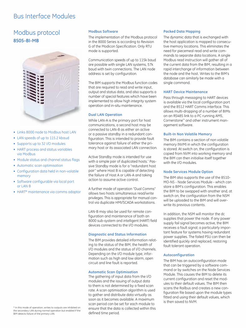
Bus Interface Modules
Modbus protocol 8505-BI-MB
• Links8000nodetoModbushostLAN
• LANspeedsofupto115.2kbaud
• Supportsupto32I/Omodules
• HARTprocessandstatusvariables via Modbus
• Modulestatusandchannelstatusflags
• Automaticscanoptimisation
• Configurationdataheldinnon-volatilememory
• Softwareconfigurablevialocalport or LAN B
• HART® maintenance via comms adaptor
Modbus SoftwareThe implementation of the Modbus protocol in the 8000 Series is according to Revision G of the Modicon Specification. Only RTU mode is supported.
Communication speeds of up to 115k baud are possible with single LAN systems, 57k baud with twin connections. The LAN node address is set by configuration.
The BIM supports the Modbus function codes that are required to read and write input, output and status data, and also supports a number of special features which have been implemented to allow high integrity system operation and in-situ maintenance.
Dual LAN OperationWhile LAN-A is the primary port for host communications, a second host may be connected to LAN-B as either an active or a passive standby in a redundant con-figuration. This is intended to provide fault tolerance against failure of either the pri-mary host or its associated LAN connection.
Active Standby mode is intended for use with a simple pair of duplicated hosts.* Pas-sive Standby mode is for a “redundant host pair” where Host B is capable of detecting the failure of Host A or LAN-A and taking action to assume active control.
A further mode of operation “Dual Comms” allows two hosts simultaneous read/write privileges. This is appropriate for manual con-trol via duplicate HMI/SCADA workstations.
LAN-B may also be used for remote con-figuration and maintenance of both an 8000 sub-system and intelligent (HART) field devices connected to the I/O modules.
Diagnostic and Status InformationThe BIM provides detailed information relat-ing to the status of the BIM, the health of I/O modules and the status of I/O channels. Depending on the I/O module type, infor-mation such as high and low alarm, open circuit and line fault is reported.
Automatic Scan OptimisationThe gathering of input data from the I/O modules and the issuing of output data to them is not determined by a fixed scan rate. A scan optimisation algorithm is used to gather and distribute data virtually as soon as it becomes available. A maximum scan period can be set for each module to ensure that the data is collected within this defined time period.
Packed Data MappingThe dynamic data that is exchanged with the host application is mapped to consecu-tive memory locations. This eliminates the need for piecemeal read and write com-mands to separate data locations. A single Modbus read instruction will gather all of the current data from the BIM, resulting in a rapid interchange of information between the node and the host. Writes to the BIM’s database can similarly be made with a single command.
HART Device MaintenancePass through messaging to HART devices is available via the local configuration port and the 8512 HART Comms interface. This allows multi-dropping of a number of BIMs on an RS485 link to a PC running AMS, Cornerstone™ and other instrument man-agement software.
Built-In Non Volatile MemoryThe BIM contains a section of non volatile memory (NVM) in which the configuration is stored. At switch on, the configuration is copied from NVM into working memory and the BIM can then initialise itself together with the I/O modules.
Node Services Module OptionThe BIM also supports the use of the 8510-MO-NS - Node Services Module - which can store a BIM’s configuration. This enables the BIM to be swapped with another and, at switch on, the configuration from the NSM will be uploaded to the BIM and will over-write its previous contents.
In addition, the NSM will monitor the dc supplies that power the node. If any power supply fail signal becomes active, the BIM receives a fault signal; a particularly impor-tant feature for systems having redundant power supplies. The failed PSU can then be identified quickly and replaced, restoring fault tolerant operation.
AutoconfigurationThe BIM has an autoconfiguration mode that can be triggered by a software com-mand or by switches on the Node Services Module. This causes the BIM to delete its current configuration and reset the mod-ules to their default values. The BIM then scans the Railbus and creates a new con-figuration file based upon the module types fitted and using their default values, which is then saved to NVM.
* In this mode of operation, writes to outputs are inhibited on the secondary LAN during normal operation but enabled if the BIM detects failure of the primary LAN.

Bus Interface Modules
Modbus protocol 8505-BI-MB
MODULE SPECIFICATION
LAN INTERFACE
Transmission protocol Modbus (RTU mode)Transmission rates 1.2 - 115.2 kbits/sBy mode
Single LAN mode 115.2 kbit/s (max.)Passive standby mode 115.2 kbit/s (max.)Active standby mode 19.2 kbit/s (max.)Dual comms. mode 19.2 kbit/s (max.)Remote config mode 19.2 kbit/s (max.)
Transmission standard RS485 or RS422Bus Insulation 500 V Action on software malfunction Halt CPU / Reset CPU
CONFIGURATION
The BIM can be configured either by using 8455-SW-CF software running on a PC or by transfer of a configura-tion from the 8510-NS-MO Node Services Module. An autoconfiguration option is also provided.
Address setting Software settable in BIM or switch settable using 8510-NS–MO Node Services Module.
RESPONSE TIMES
Modbus message response time < 4 ms
POWER SUPPLIES
Railbus (12V) current 260mA(typ.) 300 mA (max.)
MECHANICAL
Module width 63mmWeight (approx.) 320 g
See System Specification for other parameters.
LED INDICATORS
MODBUS FUNCTIONS SUPPORTED
Read Coil Status (Function 01)Reads a range of single-bit flags that show the status
of Discrete Output channels. This allows the host to confirm the states to which the BIM has set the Discrete Outputs.
Read Input Status (Function 02)Reads a range of single-bit flags that show the status of Discrete Input channels. This allows the host to monitor the latest reported state of the Discrete Inputs.
Read Holding Registers (Function 03)Readsarangeof16-bitregistersthatcontainthestatusof Analog Outputs. This allows the host to confirm the states to which the BIM has set the Analog Outputs.
Read Input Registers (Function 04)Readsarangeof16-bitregistersthatcontainthestatusof Analog Input channels. This allows the host to monitor the latest reported state of the Analog Inputs.
Force Single Coil (Function 05)Requests the BIM to force a specified coil to a ‘1’ or a ‘0’. This could be used, for example, to switch a DO channel or make it pulse.
Preset Single Register (Function 06)Writesa16-bitvaluetoaspecifiedBIMregister-eitherto set an Analog Output or. to preset a DI counter.
Return Diagnostic Register (Function 08)Requests that the slave reads the contents of its diagnostic register and returns the binary data values to the master, according to the specified sub-function code; i.e. Return Query Data (00) or Return Diagnostic Register (02)
Force Multiple Coils (Function 15)Requests the BIM to force a specified range of coils to a ‘1’ or a ‘0’. This could be used, for example, to switch DO channels or make them pulse.
Preset Multiple Registers (Function 16)Writesa16-bitvaluetoaspecifiedrangeofBIMregis-ters - for example to set Analog Outputs.
Report Slave ID (Function 17)The Report Slave ID function permits the user to obtain information on the slave type and ‘RUN’ status.
Power (green)
OFF ON Flashing
Power fail Power OK –
Fault (red)
OFF ON Flashing
Normal Failsafe or faultConfiguration
required
LAN A & LAN B (yellow)
OFF ON Flashing
LAN disconnectedInternal
Comms. OKNo comms. or fault
Config (yellow)
OFF ON Flashing
Configurator not connected
Configurator con-nected to local port
Configuring via LAN
Railbus (yellow)
OFF ON Flashing
Railbus Fault Railbus OK –

Bus Interface Modules
Configuration Software 8455-SW-CF
• Windows™ Explorer - style interface
• UsedtoconfigureBusInterfaceModules
• LocalorremoteconfigurationviaLAN
• Dynamicviewingofreal-timedata
• Singleprojectfileformulitplenodes
The 8455 software is one of the methods for configuring Bus Interface Modules (BIMs) in an Process I/O™ node. It runs on a PC, under the familiar WindowsTM operating system. The PC can be linked to the BIM using either a local cable link or via a secondary LAN connection, where available.
The BIM is the interface between the I/O modules and the host controller, and must be configured to permit correct operation. The BIM needs to be told the identity of each I/O module fitted and values of relev-ent parameters. Parameters must also be defined for LAN communication with the host controller.
Project FileThe configuration information is contained inaprojectfile.Aprojectfilecanbecreatedfor a single BIM or for multiple BIMs, e.g. on a network, each of which can accommodate up to 32 I/O modules. The configuration information may then be downloaded to the individual BIMs on the network.
User InterfaceThe main screen of the Configurator has a conventional Windows Menu and Toolbar display at the top. The main body of the screen is then split to show a “navigation tree” for the network on the left-hand side and the BIM/module parameters on the right.
Module Attributes & ParametersThe software can display the hardware and software revision levels of the both the BIM and the I/O modules. Each module has its own set of parameters and these appear with default values when the mod-ule is first added to the system. These can then be edited individually to specify the required system.
Dynamic dataReal-time data is available on-screen if the configuration link (serial or LAN) is in place. The viewable data includes primary variables as well as status parameters. This can be refreshed continually or when the operator requires a screen refresh. When in continuous refresh mode, the time between module data reads can also be viewed. Alternatively, the Configurator can be oper-ated“offline”forsimpleprojectfilecreation.
Upload BIM DataConfiguration data already contained in a BIM can be uploaded to the Configurator. This can be saved as a PC file and copied to other BIMs. PC files that were created for earlier reversions of the BIM firmware can
also be opened and edited for use with the latest versions of the BIM.
Open Database StructureThe Configurator contains a Microsoft® Access open structure database in which the configuration data is held.
Simple Tabbed PagesThe right hand side of the screen contains information on any item that is highlighted in the navigation tree to the left. With the network icon selected, three tabbed pages of information are available (see Fig 1).
These pages define and describe the net-work protocol, the BIMs that are attached tothenetworkandthedetailsoftheprojectcontained in the overall configuration file.
Selection of the BIM icon in the naviga-tion area reveals five pages of information and settings (see Fig 2) for the BIM. These pages provide information that relate to the selected BIM and its specific network set-tings and the I/O modules attached to it .
Finally, clicking on an I/O module provides a further set of five pages of module infor-mation and settings (Fig 3). These pages contain details of the software and hard-ware revision levels of the chosen module,
Fig 1 - Configuration file details
Fig 2 - BIM attributes

Bus Interface Modules
Configuration Software 8455-SW-CF
SPECIFICATIONS
PC SYSTEM REQUIREMENTS
• IntelPentium® processor (recommended)• Microsoft® Windows™ 95, 98, 2000 or NT4 operating
system• RAMcapacity–asappropriateforoperatingsystem• Atleastoneavailableserialport(COM1,2,3or4)• 1MBharddiskspace+spaceforusercreated
configuration files
BIM COMMUNICATION PORT SETTINGS
Speeds 1,200 – 38,400 baudParity Odd, Even or NoneData bits 8Stop bits 1Protocol SLIP
ASSOCIATED LITERATURE
INM8455 Instruction manual, BIM Configuration Software
TO ORDER
Configurator with RS232 cable 8455-SW-CFConfiguratorwithoutRS232cable 8456-SW-CFRS232cable 8460-CA-CF
(The software and any release notes are supplied on a CD ROM.)
IMPORTANT NOTE: This software is designed for use with the latest 8505-BI-MB BIM that has version 2.x firmware. It is NOT compatible with version 1 BIMs. However, .csv or .ssf files created for use in version 1 BIMs can be imported to create configuration files for version 2 BIMs.
Windows™ is a trademark of Microsoft® Corporation
Intel and ‘Pentium®’ are trademarks of Intel Corporation
the condition of its various status flags, the user definable variables and, if connected “live”, the current value of each variable.
All of these pages are provided automati-cally when a module is added.
Fig 3 - I/O module dynamic data
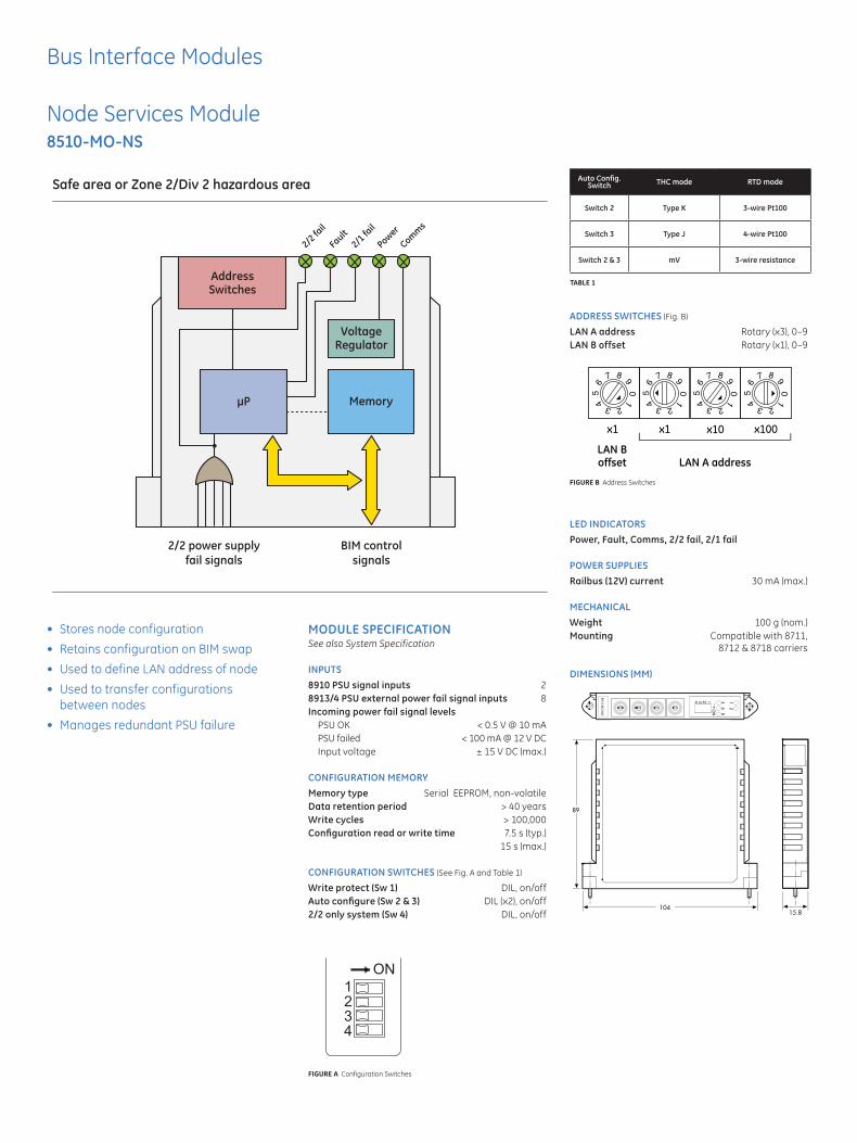
Bus Interface Modules
Node Services Module 8510-MO-NS
• Storesnodeconfiguration
• RetainsconfigurationonBIMswap
• UsedtodefineLANaddressofnode
• Usedtotransferconfigurations between nodes
• ManagesredundantPSUfailure
Safe area or Zone 2/Div 2 hazardous area
2/2 power supplyfail signals
AddressSwitches
VoltageRegulator
MemoryµP
2/2 fa
il
2/1 fa
il
Power
Comms
Fault
BIM controlsignals
MODULE SPECIFICATIONSee also System Specification
INPUTS8910 PSU signal inputs 28913/4 PSU external power fail signal inputs 8 Incoming power fail signal levels
PSU OK < 0.5 V @ 10 mAPSU failed < 100 mA @ 12 V DCInput voltage ± 15 V DC (max.)
CONFIGURATION MEMORYMemory type Serial EEPROM, non-volatileData retention period > 40 yearsWrite cycles > 100,000Configuration read or write time 7.5 s (typ.) 15 s (max.)
CONFIGURATION SWITCHES (See Fig. A and Table 1)
Write protect (Sw 1) DIL, on/offAuto configure (Sw 2 & 3) DIL (x2), on/off2/2 only system (Sw 4) DIL, on/off
ADDRESS SWITCHES (Fig. B)
LAN A address Rotary (x3), 0–9LAN B offset Rotary (x1), 0–9
LED INDICATORSPower, Fault, Comms, 2/2 fail, 2/1 fail
POWER SUPPLIESRailbus (12V) current 30 mA (max.)
MECHANICALWeight 100 g (nom.)Mounting Compatible with 8711, 8712&8718carriers
DIMENSIONS (MM)
Auto Config.Switch THC mode RTD mode
Switch 2 Type K 3-wire Pt100
Switch 3 Type J 4-wire Pt100
Switch 2 & 3 mV 3-wire resistance
TABLE 1
15.8104
89
FIGURE A Configuration Switches
LAN A addressLAN Boffset
x1 x1 x10 x100
0 1 2 3 4
5 6
7 8 9
0 1 2 3 4
5 6
7 8 9
0 1 2 3 4
5 6
7 8 9
0 1 2 3 4
5 6
7 8 9
FIGURE B Address Switches

Bus Interface Modules
HART Interface Module 8512-IF-HA
• Supportsupto256HARTdevicespernode
• SupportsAMSsoftware
• SimplifiesmaintenanceofHART field devices
• MountableinZone2or Div 2 hazardous areas
• Onlyonerequiredper8000node
Safe area
8000node 1
8000node 2
8512 8512
Safe area or Zone 2/Div 2 hazardous area
RS232/RS485Converter Workstation PC
Running “AMS” software(Asset Management Solutions)
31 nodes max.
MODULE SPECIFICATIONSee also System Specification
HOST INTERFACEElectrical specification RS485Physical medium 2-wire multidrop Number of nodes per workstation 31 (max.)Unit addresses (software configurable) 1-31Baud rate (software configurable)
1.2,9.6,19.2and38.4baudInstrument management software supported AMS (contact GE Intelligent Platforms for further options)
8000 INTERFACEConnection to BIM Via Configurator portHART devices per mode 256(max.)
HAZARDOUS AREA APPROVALSLocation of 8512-IF-HA Safe area or Class 1, Div 2, Groups A, B, C, D, T4 Hazardous locationorZone2,IICT4Hazardouslocation
ISOLATIONPort to port psu 250Vacrms(toEN61010-1) (tested at 2.3 kV ac rms for 1 min.)
LED INDICATORSLEDs for status indication of HOST and 8000 port
ELECTRICALPower supply voltage (Vs) 20-35 V dcCurrent required
at 20 V 135 mA (max.)at 24 V 115 mA (max.)at 35 V 75 mA (max.)
Connections Screw terminalsConductor cross-section 2.5 mm2 (max.)
MECHANICALMounting Directly on to T- or G- section DIN railCasing PolyamideModule width 40 mmWeight 100 g
CIRCUIT AND WIRING DIAGRAM
DIMENSIONS AND MOUNTING (MM)
15
40
Terminals1,2,3,4,5,
7984
.5
85.5
90.5
Terminals7,8,9,10,11,12
T-section rail (DIN 46277)
G-section rail (DIN 46277)
To 8000Configurator port
Lever out withscrewdriver torelease module
RS232 to 8000Configuration Port
Rx
Tx
GND
8000Interface
Micro-processor
section
Hostinterface
RS485 to PC Workstation
20-35 V DC
Data (+)
Data (–)
GND
Supply
D9
8512-IF-HA
1
2
3
4
5
6
7
8
9
10
11
12

GE Intelligent Platforms Contact Information
Americas: 1 800 433 2682 or 1 434 978 5100 Global regional phone numbers are listed by location on our web site at www.ge-ip.com/contact
www.ge-ip.com
About GE Intelligent Platforms
GE Intelligent Platforms, a General Electric Company (NYSE: GE), is an experienced high-performance technology company and a global provider of hardware, software, services, and expertise in automation and embedded computing. We offer a unique foundation of agile, advanced and ultra-reliable technology that provides customers a sustainable advantage in the industries they serve, including energy, water, consumer packaged goods, government and defense, and telecommunications. GE Intelligent Platforms is a worldwide company headquartered in Charlottesville, VA and is part of GE Home and Business Solutions. For more information, visit www.ge-ip.com.
©2010 GE Intelligent Platforms, Inc. All rights reserved.All other brands or names are property of their respective holders.Specificationsaresubjecttochangewithoutnotice. 07.10 GFA-1713
Bus Interface Module

EUROPE (EMEA) Tel: +44 (0)1582 723633 Fax: +44 (0)1582 422283AMERICAS Tel: +1 603 926 0090 Fax: +1 603 926 1899ASIA PACIFIC Tel: +65 487 7887 Fax: +65 487 7997E-mail: [email protected] Web site: www.mtl-inst.com
June 2004
Module carriers - Overview
GeneralCarriers are the building blocks onwhich the 8000 system isassembled. They distribute thebasic power supply services to themodules, and provide the communications route betweenthe Bus Interface Module (BIM) orController and the I/O modules.Most carriers can be mounted onDIN rail or directly to a flat surfaceand may be joined end-to-end toextend the size of an installation.Multipin connectors at the end ofeach carrier carry the systempower supply and internal“Railbus” communications acrossto the next carrier.All I/O module carriers have theirown independent earthing/grounding strip, with screw terminals, to terminate thescreens/shields of field-wiringcables. At each end of the stripthere is a separate terminal toenable it to be linked to othercarriers, or to the system ground,as required.
Node services carrier-NSMThis node services carrier will accommodateone BIM and a node services module. It isthe recommended BIM carrier for all ACpowered nodes because it supports “powerhealth” management. This carrier willsupport Modbus or Profibus-DP BIMs.It is also recommended for DC powerednodes that are exclusively 2/1, i.e. whereno 2/2 I/O modules are required. For theseapplications, it is commonly used with thepower supply carrier (see this page) .
BIM-only carrierThis carrier provides an alternative to anode services carrier - NSM when a nodeservices module is not required. This carrierwill support Modbus or Profibus-DP BIMs. Itis commonly used with the power supplycarrier (see this page).
Node services carrier-BIMThese two node services carriers willaccommodate one BIM, a node servicesmodule, two system DC power supplies andfour 2/2 I/O modules. One carrier (8711)supports the Modbus BIM and the other(8712) supports the Profibus-DP BIM. These carriers are recommended for DCpowered nodes that use 2/2, or a mixtureof 2/2 and 2/1 I/O modules.
Controller carrierThe controller carrier provides a mountingplatform for up to two controllers or EBIMs(8521-XX-XX). It can also accommodate aPower Supply Monitor module (8410-NS-PS), to monitor up to seven system powersupplies in the node and alert the controllerto failures.
I/O Module carriersI/O Module carriers are available in general purpose (2/2) and 2/1 format. As asafeguard, these two types cannot beconnected to each other because of the different multipin connectors used. The onlyway to connect the two types is by placing aRailbus Isolator (on its carrier) between them.Within these basic formats, 4 and 8 module carriers are available and they may bejoined in any combination to suit noderequirements.
64 module addressingThe 8521 controller/EBIM is capable ofaddressing up to 64 modules, unlike theBIM models 8502 and 8505, which willaddress a maximum of 32.Two carriers, models 8709-CA-08 (2/2)and 8729-CA-08 (2/1), are available withadditional addressing lines to build a nodewith up to 64 modules. If 64-slot addressing
is required for a node, these carrier typesmust be used exclusively, i.e. they cannot bemixed with 32-slot address carriers.Note: The 8521 controller/eBIM can alsobe configured to a 32 module limit and maythen use 32-slot address carriers.
Power supply carrierThis carrier is used to mount the 8910-PS-DCsystem power supply module which providessystem power for DC power nodes. It is oftenused to support the node services carrier-NSM or the BIM-only carrier.
IS power supply modulecarrier The 8920-PS-DC field power supply moduleprovides power for 2/1 I/O modules andrequires its own carrier to mount it. The carrier mounts in-line with 8- and 4-module2/1 carriers, maintaining the Railbus connections through its edge connectors.This carrier may be used in 32-slot or 64-slotaddress nodes.
Railbus isolator carrierWhen a node has IS field wiring terminatingon it, an 8922-RB-IS Railbus isolator must beused between 2/2 and 2/1 carrier types.This is to prevent possible mains-voltagefault conditions from being propagated, viathe Railbus, to the IS field wiring. TheRailbus isolator has its own carrier – 8723-CA-RB. This carrier may be used in 32-slotor 64-slot address nodes.
Carrier extendersIf the chosen field enclosure will notaccommodate a single, end to end line ofcarriers, extenders can be fitted to enablethe carriers to be continued on another line.The extenders are left and right handed and connect to the ends of the I/Omodule carriers using the multipin connectors. A multicore cable is used to linkthe data and address bus between the carriers.General purpose (2/2) and 2/1 extendershave different connectors to prevent accidental cross connection of the two types.Carrier extenders may be used in 32-slot or64-slot address nodes.
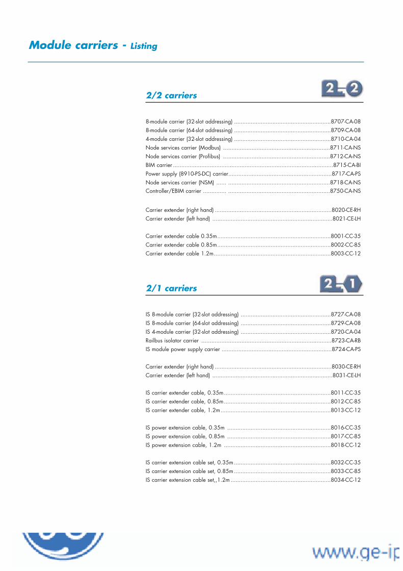
EUROPE (EMEA) Tel: +44 (0)1582 723633 Fax: +44 (0)1582 422283AMERICAS Tel: +1 603 926 0090 Fax: +1 603 926 1899ASIA PACIFIC Tel: +65 487 7887 Fax: +65 487 7997E-mail: [email protected] Web site: www.mtl-inst.com
June 2004
Module carriers - Listing
2/2 carriers
8-module carrier (32-slot addressing) ..........................................................8707-CA-088-module carrier (64-slot addressing) ..........................................................8709-CA-084-module carrier (32-slot addressing) ..........................................................8710-CA-04Node services carrier (Modbus) ................................................................8711-CA-NSNode services carrier (Profibus) ................................................................8712-CA-NSBIM carrier ................................................................................................8715-CA-BIPower supply (8910-PS-DC) carrier..............................................................8717-CA-PSNode services carrier (NSM) ...... .............................................................8718-CA-NSController/EBIM carrier .............. .............................................................8750-CA-NS
Carrier extender (right hand) ......................................................................8020-CE-RHCarrier extender (left hand) ........................................................................8021-CE-LH
Carrier extender cable 0.35m....................................................................8001-CC-35Carrier extender cable 0.85m....................................................................8002-CC-85Carrier extender cable 1.2m......................................................................8003-CC-12
2/1 carriers
IS 8-module carrier (32-slot addressing) ......................................................8727-CA-08IS 8-module carrier (64-slot addressing) ......................................................8729-CA-08IS 4-module carrier (32-slot addressing) ......................................................8720-CA-04Railbus isolator carrier ..............................................................................8723-CA-RBIS module power supply carrier ..................................................................8724-CA-PS
Carrier extender (right hand) ......................................................................8030-CE-RHCarrier extender (left hand) ........................................................................8031-CE-LH
IS carrier extender cable, 0.35m................................................................8011-CC-35IS carrier extender cable, 0.85m................................................................8012-CC-85IS carrier extender cable, 1.2m..................................................................8013-CC-12
IS power extension cable, 0.35m ..............................................................8016-CC-35IS power extension cable, 0.85m ..............................................................8017-CC-85IS power extension cable, 1.2m ................................................................8018-CC-12
IS carrier extension cable set, 0.35m..........................................................8032-CC-35IS carrier extension cable set, 0.85m..........................................................8033-CC-85IS carrier extension cable set,,1.2m ............................................................8034-CC-12

EUROPE (EMEA) Tel: +44 (0)1582 723633 Fax: +44 (0)1582 422283AMERICAS Tel: +1 603 926 0090 Fax: +1 603 926 1899ASIA PACIFIC Tel: +65 487 7887 Fax: +65 487 7997E-mail: [email protected] Web site: www.mtl-inst.com
June 2004
8-module carrier 8707-CA-08
32-slot address bus*
accepts up to eight I/O modules and field terminals
printed wiring board
rugged polycarbonate moulding
DIN rail or panel mounting
carries control signals and data on Railbus
distributes DC power to modules
distributes Bussed Field Power to modules
isolated earthing bar for cable screens/shields
CARRIER SPECIFICATIONSee also System Specification
HAZARDOUS AREA APPROVALSLocation of node.........Class 1, Div 2, Groups A, B, C, D T4 hazardous location or ......Zone 2, IIC T4 hazardous location Location of field wiring ...........................................As nodeField terminals accepted......................General purpose, 2/2I/O modules accepted ........................ General purpose, 2/2
ELECTRICALRailbus connectors....................................female in, male outModule address range.................................................1–32Bussed field power supply (optional)Two 8-pin connectors are provided at the top rear of the carrier to connect power supplies for ‘field power’. Such supplies are routedthrough certain I/O module to provide power to field circuits.
MATERIALSCarrier moulding......................Modified poly-phenylene oxidePrinted wiring board ...........Epoxy resin woven glass laminate
ENVIRONMENTALAmbient tempOperating, .....................................................– 40°C to + 70°CStorage..........................................................– 40°C to + 85°CRelative Humidity .....................5 to 95% RH (non-condensing)Vibration and Shock.................See System specification sheet
MECHANICALDimensions...............................342 (w) x 170 (d) x 22 (h) mmWeight..........................................................................680 gMounting methods ...............................Flat panel or DIN rail DIN-rail types........‘Top hat’ 35 x 7.5 mm rail or 35 x 15 mm rail to EN 50022........................................................G-section rail to EN 50035
Note: A second connector uses the same pin assignments for
modules 5 & 6 and 7 & 8.
* Must not be mixed with 64-slot address carriers
1 I/O Modules 1 & 2
2 –ve (or Neutral)
3 I/O Modules 1 & 2
4 +ve (or Live)
5 I/O Modules 3 & 4
6 +ve (or Live)
7 I/O Modules 3 & 4
8 –ve (or Neutral)
Terminal Bussed Field Power
Module carriers
BUSSED FIELD POWER CONNECTIONS

EUROPE (EMEA) Tel: +44 (0)1582 723633 Fax: +44 (0)1582 422283AMERICAS Tel: +1 603 926 0090 Fax: +1 603 926 1899ASIA PACIFIC Tel: +65 487 7887 Fax: +65 487 7997E-mail: [email protected] Web site: www.mtl-inst.com
Jul 2005
1 I/O modules 1 & 22 –ve (or Neutral)3 I/O modules 1 & 24 +ve (or Live)5 I/O modules 3 & 46 +ve (or Live)7 I/O modules 3 & 48 –ve (or Neutral)
Terminal Function
Module carriers
8-module carrier - extended addressing 8709-CA-08
BUSSED FIELD POWER CONNECTIONS
Note: A second connector uses the same pin assignments for
modules 5 & 6 and 7 & 8.
* For use only with 8521-XX-XX controller/EBIM, and cannot be
mixed with 32-slot address carriers
64-slot address bus*
accepts up to eight I/O modules and field terminals
printed wiring board
rugged polycarbonate moulding
DIN rail or panel mounting
carries control signals and data on Railbus
distributes DC power to modules
distributes Bussed Field Power to modules
isolated earthing bar for cable screens/shields
CARRIER SPECIFICATIONSee also System Specification
HAZARDOUS AREA APPROVALSLocation of carrier.........Class 1, Div 2, Groups A, B, C, D T6 hazardous location or ......Zone 2, IIC T6 hazardous location Location of field wiring .........................................As carrierField terminals accepted......................General purpose, 2/2I/O modules accepted ........................ General purpose, 2/2Applicable standards: Factory Mutual Research Co., Class No. 3611 for Class I,
Division 2, Groups A, B, C, D hazardous locations
CSA Std C22.2 No. 213 for Class I, Division 2, Groups A, B, C, D hazardous locations
ATEX Category 3 (for Zone 2 installation)to EN50021:1999 protection type ‘n’
ELECTRICALRailbus connectors....................................female in, male outModule address range.................................................1–64Bussed field power supply (optional)Two 8-pin connectors are provided at the top rear of the carrier to connect power supplies for ‘field power’. These supplies are routedthrough I/O modules that require power for their field circuits.
MATERIALSCarrier moulding......................Modified poly-phenylene oxidePrinted wiring board ...........Epoxy resin woven glass laminate
ENVIRONMENTALAmbient tempOperating, .....................................................– 40°C to + 70°CStorage..........................................................– 40°C to + 85°CRelative Humidity .....................5 to 95% RH (non-condensing)Vibration and Shock .........................See System specification
MECHANICALDimensions...............................342 (w) x 170 (d) x 22 (h) mmWeight..........................................................................680 gMounting methods ...............................Flat panel or DIN rail DIN-rail types........‘Top hat’ 35 x 7.5 mm rail or 35 x 15 mm rail to EN 50022........................................................G-section rail to EN 50035

EUROPE (EMEA) Tel: +44 (0)1582 723633 Fax: +44 (0)1582 422283AMERICAS Tel: +1 603 926 0090 Fax: +1 603 926 1899ASIA PACIFIC Tel: +65 487 7887 Fax: +65 487 7997E-mail: [email protected] Web site: www.mtl-inst.com
June 2004
BUSSED FIELD POWER CONNECTIONS
* Must not be mixed with 64-slot address bus carriers
4-module carrier 8710-CA-04
Module carriers
32-slot address bus*
accepts up to four I/O modules and field terminals
printed wiring board
rugged polycarbonate moulding
DIN rail or panel mounting
carries control signals and data on Railbus
distributes DC power to modules
distributes Bussed Field Power to modules
isolated earthing bar for cable screens/shields
CARRIER SPECIFICATIONSee also System Specification
HAZARDOUS AREA APPROVALS
Location of node.........Class 1, Div 2, Groups A, B, C, D T4 hazardous location or ......Zone 2, IIC T4 hazardous location Location of field wiring ...........................................As nodeField terminals accepted......................General purpose, 2/2I/O modules accepted ........................ General purpose, 2/2
ELECTRICALRailbus connectors....................................female in, male outModule address range.................................................1–32Bussed field power supply (optional)An 8-pin connector is provided at the top rear of the carrier to connect power supplies for ‘field power’. Such supplies are routedthrough certain I/O module to provide power to field circuits.
MATERIALSCarrier moulding......................Modified poly-phenylene oxidePrinted wiring board ...........Epoxy resin woven glass laminate
ENVIRONMENTALAmbient tempOperating ......................................................– 40°C to + 70°CStorage..........................................................– 40°C to + 85°CRelative Humidity .....................5 to 95% RH (non-condensing)Vibration and Shock.................See System specification sheet
MECHANICALDimensions...............................178 (w) x 170 (d) x 22 (h) mmWeight ..........................................................................350 gMounting methods ...............................Flat panel or DIN rail DIN-rail types........‘Top hat’ 35 x 7.5 mm rail or 35 x 15 mm rail to EN 50022........................................................G-section rail to EN 50035
1 I/O Modules 1 & 2
2 –ve (or Neutral)
3 I/O Modules 1 & 2
4 +ve (or Live)
5 I/O Modules 3 & 4
6 +ve (or Live)
7 I/O Modules 3 & 4
8 –ve (or Neutral)
Terminal Bussed Field Power

EUROPE (EMEA) Tel: +44 (0)1582 723633 Fax: +44 (0)1582 422283AMERICAS Tel: +1 603 926 0090 Fax: +1 603 926 1899ASIA PACIFIC Tel: +65 487 7887 Fax: +65 487 7997E-mail: [email protected] Web site: www.mtl-inst.com
June 2004
Node services carrier 8711-CA-NS
Module carriers
Modbus BIM
accommodates one BIM, two PSUs and four I/O modules
screw terminals for LAN
DIN rail or panel mounting
printed wiring board
rugged polycarbonate moulding
routes Bussed Field Power to I/O modules
isolated earthing bar for cable screen/shield
CARRIER SPECIFICATIONSee also System Specification
CARRIER MOUNTING MODULESPSU Modules (main and redundant) ................8910-PS-DCBus Interface Module ..........................(Modbus) 8505-BI-MBNode Services Module .....................................8510-NS-MOI/O modules .............................general purpose (2/2) various
HAZARDOUS AREA APPROVALSLocation of node.........Class 1, Div 2, Groups A, B, C, D T4 hazardous location or ......Zone 2, IIC T4 hazardous areaLocation of field wiring......................................As per nodeField terminals accepted .....General purpose or Zone 2/Div 2I/O modules accepted ........General purpose or Zone 2/Div 2
ELECTRICALRailbus connector.....................................................male outExternal dc power supply (optional)A 6-pin connector is provided at the top/rear of the carrier to connect a 12.0 V dc (±5%) power supply. This is an alternative to thecarrier mounted PSU modules.Bussed field power supply (optional)An 8-pin connector is provided at the top rear of the carrier to connect power supplies for ‘field power’. Such supplies are routedthrough certain I/O module to provide power to field circuits.
LAN CONNECTORS
LAN A ...............................................6-way, screw-terminal (x2)LAN B ...............................................6-way, screw-terminal (x2)
MATERIALSCarrier moulding......................Modified poly-phenylene oxidePrinted wiring board ...........Epoxy resin woven glass laminate
ENVIRONMENTALAmbient tempOperating ......................................................– 40°C to + 70°CStorage..........................................................– 40°C to + 85°CRelative Humidity .....................5 to 95% RH (non-condensing)Vibration and Shock.................See System specification sheet
MECHANICALDimensions...............................342 (w) x 170 (d) x 22 (h) mmWeight (approx.).........................................................680 gMounting methods ................Flat panel (4 fixings) or DIN rail DIN-rail types ..................‘Top hat’, 7.5 x 35 mm or 15 x 35 mm to EN 50022............................................................G-section, to EN 50035

EUROPE (EMEA) Tel: +44 (0)1582 723633 Fax: +44 (0)1582 422283AMERICAS Tel: +1 603 926 0090 Fax: +1 603 926 1899ASIA PACIFIC Tel: +65 487 7887 Fax: +65 487 7997E-mail: [email protected] Web site: www.mtl-inst.com
June 2004
8711-CA-NS continued
1 Rx +
2 Tx +
3 Rx –
4 Tx –
5 Gnd
6 Gnd
Terminal Assignment
LAN INTERFACE
1 Test Point 1 I/O Modules 1 & 2
2 0 V –ve (or Neutral)
3 +12 V I/O Modules 1 & 2
4 +12 V +ve (or Live)
5 0 V I/O Modules 3 & 4
6 Test Point 2 +ve (or Live)
7 Not applicable I/O Modules 3 & 4
8 Not applicable –ve (or Neutral)
Terminal External Power Bussed Field Power
POWER SUPPLY CONNECTIONS
External Power Bussed Field Power
!"
!"
!"
#
!"
$
%&'
( ')
*'%+)
)!*%,-
#.#.
$/$/
Mode 1: RS422 –
Mode 2: RS485 –no termination
Mode 3: RS485terminated
Mode 4: RS485terminated and biased
Mode Switch positions Termination
LAN DIL SWITCHESOne switch block per LAN. Operating mode set with switches.
0
1
2
#32
0 #32
Pins for power supplies are provided in pairs. This enables one pin to beused for the supply input and the second to loop to another connector, when required.
Each LAN has duplicate connectionswired in parallel - pin 1 to pin 1, pin2 to pin 2, etc.
0
1
2
Module carriers

EUROPE (EMEA) Tel: +44 (0)1582 723633 Fax: +44 (0)1582 422283AMERICAS Tel: +1 603 926 0090 Fax: +1 603 926 1899ASIA PACIFIC Tel: +65 487 7887 Fax: +65 487 7997E-mail: [email protected] Web site: www.mtl-inst.com
June 2004
Module carriers
Node services carrier 8712-CA-NS
Profibus BIM
accommodates one BIM, two PSUs and four I/O modules
sub-miniature, 9-pin, D connectors for LAN
DIN rail or panel mounting
printed wiring board
rugged polycarbonate moulding
routes Bussed Field Power to I/O modules
isolated earthing bar for cable screen/shield
CARRIER SPECIFICATIONSee also System Specification
CARRIER MOUNTING MODULESPSU Modules (main and redundant) ................8910-PS-DCBus Interface Module .......................(Profibus-DP) 8502-BI-DPNode Services Module .....................................8510-NS-MOI/O modules .............................general purpose (2/2) various
HAZARDOUS AREA APPROVALSLocation of node.........Class 1, Div 2, Groups A, B, C, D T4 hazardous location or ......Zone 2, IIC T4 hazardous areaLocation of field wiring......................................As per nodeField terminals accepted .....General purpose or Zone 2/Div 2I/O modules accepted ........General purpose or Zone 2/Div 2
ELECTRICALRailbus connector.....................................................male outExternal dc power supply (optional)A 6-pin connector is provided at the top/rear of the carrier to connect a 12.0 V dc (±5%) power supply. This is an alternative to thecarrier mounted PSU modules.Bussed field power supply (optional)An 8-pin connector is provided at the top rear of the carrier to connect power supplies for ‘field power’. Such supplies are routedthrough certain I/O module to provide power to field circuits.
LAN CONNECTORSLAN A ................................9-way ‘D’ sub-miniature, female (x2)
MATERIALSCarrier moulding......................Modified poly-phenylene oxidePrinted wiring board ...........Epoxy resin woven glass laminate
ENVIRONMENTALAmbient tempOperating ......................................................– 40°C to + 70°CStorage..........................................................– 40°C to + 85°CRelative Humidity .....................5 to 95% RH (non-condensing)Vibration and Shock.................See System specification sheet
MECHANICALDimensions...............................342 (w) x 170 (d) x 22 (h) mmWeight (approx.).........................................................680 gMounting methods ................Flat panel (4 fixings) or DIN rail DIN-rail types ..................‘Top hat’, 7.5 x 35 mm or 15 x 35 mm to EN 50022............................................................G-section, to EN 50035

EUROPE (EMEA) Tel: +44 (0)1582 723633 Fax: +44 (0)1582 422283AMERICAS Tel: +1 603 926 0090 Fax: +1 603 926 1899ASIA PACIFIC Tel: +65 487 7887 Fax: +65 487 7997E-mail: [email protected] Web site: www.mtl-inst.com
June 2004
8712-CA-NScont inued
Shield/protective ground Pin 1
RxD /TxD + Pin 3
DGND (0V) Pin 5
VP (0V) Pin 6
RxD /TxD - Pin 8
LAN connections 9-way (female)RS485 interface (x2) terminals
LAN INTERFACE
1 Test Point 1 I/O Modules 1 & 2
2 0 V –ve (or Neutral)
3 +12 V I/O Modules 1 & 2
4 +12 V +ve (or Live)
5 0 V I/O Modules 3 & 4
6 Test Point 2 +ve (or Live)
7 Not applicable I/O Modules 3 & 4
8 Not applicable –ve (or Neutral)
Terminal External Power Bussed Field Power
POWER SUPPLY CONNECTIONS
External Power Bussed Field Power
Pins for power supplies are provided in pairs. This enables one pin to beused for the supply input and the second to loop to another connector, when required.
The LAN has duplicate connections wired in parallel - pin 1 to pin 1,pin 2 to pin 2, etc.
*'%+)
!"
!"
!"
#
!"
$
%&'
'%+)
)!*%,-
.3
/
.3
/
Module carriers

EUROPE (EMEA) Tel: +44 (0)1582 723633 Fax: +44 (0)1582 422283AMERICAS Tel: +1 603 926 0090 Fax: +1 603 926 1899ASIA PACIFIC Tel: +65 487 7887 Fax: +65 487 7997E-mail: [email protected] Web site: www.mtl-inst.com
June 2004
Module carriers
accommodates Bus Interface Module
Modbus or Profibus-DP
dual LAN connections (A & B)
switchable RS485/RS422 termination options
DIN rail or panel mounting
CARRIER SPECIFICATIONSee also System Specification
LAN CONNECTORSLAN A .........................................9-pin, D, sub-minature, femaleLAN B..........................................9-pin, D, sub-minature, femaleSwitchable terminations for Modbus RS485, Modbus RS422 orProfibus-DP
CARRIER MOUNTING MODULESBus Interface Modules .....................(Profibus-DP) 8502-BI-DP ..............................................................(Modbus) 8505-BI-MB
HAZARDOUS AREA APPROVALSLocation of node..................... Zone 2, IIC T4 hazardous area.........or Class 1, Div 2, Groups A, B, C, D T4 hazardous location
ENVIRONMENTALAmbient tempOperating ......................................................– 40°C to + 70°CStorage..........................................................– 40°C to + 85°CRelative Humidity .....................5 to 95% RH (non-condensing)Vibration and Shock.................See System specification sheet
MATERIALSCarrier moulding .....................Modified Poly-Phenylene OxidePrinted wiring board ........Epoxy Resin Woven Glass Laminate
DC POWERExternal power supply ................................12.0 V dc ± 5% (via 6-pin external power connector at top/rear)
MECHANICALDimensions (overall) .................93 (w) x 170 (d) x 35 (h) mmWeight (approx.).........................................................680 gMounting methods ................Flat panel (2 fixings) or DIN rail DIN-rail types ................‘Top hat’, 7.5 x 35 mm to EN 50022...................................................or 15 x 35 mm to EN 50022........................................................or G-section, to EN 50035
BIM carrier 8715-CA-BI

EUROPE (EMEA) Tel: +44 (0)1582 723633 Fax: +44 (0)1582 422283AMERICAS Tel: +1 603 926 0090 Fax: +1 603 926 1899ASIA PACIFIC Tel: +65 487 7887 Fax: +65 487 7997E-mail: [email protected] Web site: www.mtl-inst.com
June 2004
Module carriers
LAN INTERFACE
.3
/
Pin 1 FGND/Socket FGND/Socket FGND/Socketshroud shroud shroud
Pin 2 RxD+ RxD/TxD+ NC
Pin 3 TxD+ RxD/TxD+ RxD/TxD+
Pin 4 RxD– RxD/TxD– RTS+
Pin 5 GND GND GND
Pin 6 VT VT VP
Pin 7 RxD– RxD/TxD– RTS+
Pin 8 TxD– RxD/TxD– RxD/TxD–
Pin 9 NC NC NC
Terminals Modbus Modbus Profibus-DPRS422 RS485
Pin 1 Socket shroud Socket shroud
Pin 2 RxD+ RxD/TxD+
Pin 3 TxD+ RxD/TxD+
Pin 4 RxD– RxD/TxD–
Pin 5 GND GND
Pin 6 VT VT
Pin 7 RxD– RxD/TxD–
Pin 8 TxD– RxD/TxD–
Pin 9 NC NC
Terminals Modbus ModbusRS422 RS485
LAN A
Profibus-DP applications
LAN B
Note: Pins with assignments shown in italics are normally not connected; they occur because of the ‘universal’ nature of the interface.
Note: Any required termination should be implemented in the Profibus D-type plug.
Note: Switch model may vary but switching directions remain the same.
Power supply pins are provided in pairs. This enables one pin to be usedfor the supply input and the second to loop to another connector, whenrequired.
LAN DIL SWITCHES
One switch block per LAN to determine termination and/or bias ON = switch to right; OFF = switch to left (with normal orientation) Set operating mode with switches as follows:
RS485 Nonenot terminated
Mode Switch positions Termination
Modbus applications
POWER SUPPLY CONNECTIONS
RS422 Nonenot terminated
RS422 terminatedreceiver
RS422 terminated &
biased receiver
RS485 Nonenot terminated
RS485 terminated
RS485terminated & biased
Mode Switch positions Termination
0
1
2
0
1
2
#32
0 #32
0
1
2
0
1
2
#32
0 #32
External power
1 No connection
2 0 V
3 +12 V
4 +12 V
5 0 V
6 No connection
Terminal External power
8715-CA-BIcontinued

EUROPE (EMEA) Tel: +44 (0)1582 723633 Fax: +44 (0)1582 422283AMERICAS Tel: +1 603 926 0090 Fax: +1 603 926 1899ASIA PACIFIC Tel: +65 487 7887 Fax: +65 487 7997E-mail: [email protected] Web site: www.mtl-inst.com
June 2004
Module carriers
Power supply carrier 8717-CA-PS
accomodates one 8910-PS-DC power supply
DIN rail or panel mounting
use for 2/1 only nodes with DC power feed
use with 8718-CA-NS or 8715-CA-BI with DC power feed
CARRIER SPECIFICATIONSee also System Specification
HAZARDOUS AREA APPROVALSLocation of node.........Class 1, Div 2, Groups A, B, C, D T4 hazardous location or ......Zone 2, IIC T4 hazardous location
ELECTRICAL12V dc output connector .............................6-way screw terminal
MATERIALSCarrier moulding......................Modified poly-phenylene oxidePrinted wiring board ...........Epoxy resin woven glass laminate
ENVIRONMENTALAmbient tempOperating, .....................................................– 40°C to + 70°CStorage..........................................................– 40°C to + 85°CRelative Humidity .....................5 to 95% RH (non-condensing)Vibration and Shock.................See System specification sheet
MECHANICALDimensions...........................85.5 (w) x 167 (d) x 27.4 (h) mmWeight..........................................................................200 gMounting methods ...............................Flat panel or DIN rail DIN-rail types........‘Top hat’ 35 x 7.5 mm rail or 35 x 15 mm rail to EN 50022
1
2 0 V dc
3
4
5 + 12V dc
6
Terminal Function
DC OUTPUT POWER CONNECTIONS
#$./

EUROPE (EMEA) Tel: +44 (0)1582 723633 Fax: +44 (0)1582 422283AMERICAS Tel: +1 603 926 0090 Fax: +1 603 926 1899ASIA PACIFIC Tel: +65 487 7887 Fax: +65 487 7997E-mail: [email protected] Web site: www.mtl-inst.com
May 2006
Module carriers
Node services carrier 8718-CA-NS
accommodates Bus Interface Module
accommodates Node Services Module
Modbus or Profibus-DP
dual LAN connections (A & B)
switchable RS485/RS422 termination options
eight power fail inputs
DIN rail or panel mounting
CARRIER SPECIFICATIONSee also System Specification
CARRIER MOUNTING MODULESBus Interface Modules .....................(Profibus-DP) 8502-BI-DP ..............................................................(Modbus) 8505-BI-MBNode Services Module .....................................8510-MO-NS
HAZARDOUS AREA APPROVALSLocation of node..................... Zone 2, IIC T4 hazardous area.........or Class 1, Div 2, Groups A, B, C, D T4 hazardous location
ELECTRICALRailbus connector..........................................................male outPower fail connector ................................8 pairs (screw terminal)Carrier ground terminal...................................M2 screw terminal
DC POWERExternal power ............................................12.0 V dc (±5%)A 6-pin connector is provided at the top/rear of the carrier for the connection of the power supply.
LAN CONNECTORSLAN A .........................................9-pin, D, sub-minature, femaleLAN B..........................................9-pin, D, sub-minature, femaleSwitchable terminations for Modbus RS485, Modbus RS422 orProfibus-DPNote: The screw terminal beside each LAN connector is atermination for the cable screen and should not be used as systemground.
ENVIRONMENTALAmbient tempOperating ......................................................– 40°C to + 70°CStorage..........................................................– 40°C to + 85°CRelative Humidity .....................5 to 95% RH (non-condensing)Vibration and Shock.................See System specification sheet
MATERIALSCarrier moulding .....................Modified Poly-Phenylene OxidePrinted wiring board ........Epoxy Resin Woven Glass Laminate
MECHANICALDimensions (overall) ...............178 (w) x 170 (d) x 68 (h) mmWeight (approx.).........................................................450 gMounting methods ................Flat panel (2 fixings) or DIN rail DIN-rail types ................‘Top hat’, 7.5 x 35 mm to EN 50022...................................................or 15 x 35 mm to EN 50022........................................................or G-section, to EN 50035
Power supply pins are provided in pairs. This enables one pin to be usedfor the supply input and the second to loop to another connector, whenrequired.
POWER SUPPLY CONNECTIONS
External power
1 No connection
2 0 V
3 +12 V
4 +12 V
5 0 V
6 No connection
Terminal External power

EUROPE (EMEA) Tel: +44 (0)1582 723633 Fax: +44 (0)1582 422283AMERICAS Tel: +1 603 926 0090 Fax: +1 603 926 1899ASIA PACIFIC Tel: +65 487 7887 Fax: +65 487 7997E-mail: [email protected] Web site: www.mtl-inst.com
May 2006
Module carriers
8718-CA-NScont inuedLAN INTERFACE
Pin 1 Socket Socket Socketshroud shroud shroud
Pin 2 RxD+ RxD/TxD+ NC
Pin 3 TxD+ RxD/TxD+ RxD/TxD+
Pin 4 RxD– RxD/TxD– RTS+
Pin 5 GND GND GND
Pin 6 VT VT VP
Pin 7 RxD– RxD/TxD– RTS+
Pin 8 TxD– RxD/TxD– RxD/TxD–
Pin 9 NC NC NC
Modbus Modbus Profibus-DPRS422 RS485
Terminals LAN A/B LAN A/B LAN A only
Note: Pins with assignments shown in italics are normally not connected; they occur because of the ‘universal’ nature of the interface.
LAN DIL SWITCHESOne per LAN to determine termination and/or bias ON = switch to right; OFF = switch to left (with normal orientation) Note: Switch model may vary.
.3
/
PSU POWER FAIL CONNECTOR
Eight pairs of terminals are provided forthe PSU health signals. If an 8510-MO-NS module is fittedand power fail signalling is being used:a) connect the power supply AUX and
–ve terminals to a pair as shown inthe table (right)
b) put individual wire links across eachunused terminal pairs to preventa continual alarm condition beingsignalled to the BIM.
Note: Terminals 15 and 18 are not used.
Connection pairs
Note: Switch model may vary but switching directions remain the same.
Modbus applications
RS422 Nonenot terminated
RS422 terminatedreceiver
RS422 terminated &
biased receiver
RS485 Nonenot terminated
RS485 terminated
RS485terminated & biased
Mode Switch positions Termination
0
1
2
0
1
2
#32
0 #32
0
1
2
0
1
2
#32
0 #32
Profibus-DP applications
Note: Any required termination should be implemented in the Profibus D-type plug.
RS485 Nonenot terminated
Mode Switch positions Termination
Pair 1 1 4
Pair 2 2 5
Pair 3 3 6
Pair 4 7 10
Pair 5 8 11
Pair 6 9 12
Pair 7 13 16
Pair 8 14 17
AUX –ve

EUROPE (EMEA) Tel: +44 (0)1582 723633 Fax: +44 (0)1582 422283AMERICAS Tel: +1 603 926 0090 Fax: +1 603 926 1899ASIA PACIFIC Tel: +65 487 7887 Fax: +65 487 7997E-mail: [email protected] Web site: www.mtl-inst.com
June 2004
Module carriers
Controller carrier 8750-CA-NS
accommodates two controllers/EBIMs
accommodates Power Supply Monitor module
serial port connections for controllers
manual “change state” buttons
seven* power fail inputs
panel mounting
The controller carrier provides a mounting platform for up to twocontrollers or EBIMs (8521-XX-XX). It can also accommodate aPower Supply Monitor module (8410-NS-PS) which can monitor upto seven system power supplies in the node and alert the controllerto failures. The “powerfail” signals are brought to the module via ascrew terminal block at the rear of the carrier. For each controller/EBIM there is a serial port connection on the carrier and a manuallyoperated “change state” (failover) button.
CARRIER SPECIFICATIONSee also System Specification
CARRIER MOUNTING MODULESController/EBIM (x2) ...........................................8521-XX-XXPower Supply Monitor module .........................8410-NS-PS
HAZARDOUS AREA APPROVALSLocation of carrier .................. Zone 2, IIC T6 hazardous area.........or Class 1, Div 2, Groups A, B, C, D T6 hazardous locationApplicable standards:
Factory Mutual Research Co., Class No. 3611 for Class I, Division 2, Groups A, B, C, D hazardous locations
CSA Std C22.2 No. 213 for Class I, Division 2, Groups A, B, C, D hazardous locations
ATEX Category 3 (for Zone 2 installation) to EN50021:1999 protection type ‘n’
ELECTRICALRailbus connector.....................................................male outSerial port connectors.....................9-pin, D-type (female) (x2)Power “health” connections ..........screw terminals (x7 pairs)Ground terminals ................................M4 screw terminal (x2)
DC POWERExternal power ............................................12.0 V dc (±5%)A 6-pin connector (see next page) is provided at the top of the carrier.This connection powers the Power Supply Monitor module and othermodules on carriers connected to this one. Note: This connection does not provide power to thecontroller/EBIM module(s).
ENVIRONMENTALAmbient tempOperating ......................................................– 40°C to + 70°CStorage..........................................................– 40°C to + 85°CRelative Humidity .....................5 to 95% RH (non-condensing)Vibration and Shock.........................See System Specification
MATERIALSCarrier body ..............Painted 1.6mm ZINTEC to BS EN 10152Printed wiring board ........Epoxy Resin Woven Glass Laminate
MECHANICALDimensions (footprint) .........................200 (w) x 253 (d) mmHeight (top of circuit board) .....................................28 mm
(overall) ..........................................................55 mmWeight (approx.) ......................................................1.43 kgMounting methods .................................flat panel (4 fixings)
USER CONTROLSTwo “change state” buttons, one for each controller/EBIM, areprovided on the carrier to enable the user to change the state of acontroller from master to standby, standby to offline or offline tostandby. The controller/EBIM affected by each “change state”button is indicated on the circuit board. The state change dependsupon the controller state before the button is pressed. See tablebelow for effects.
State Effect
Master Change to standby if current standby is healthy
Standby Change to offline state
Backup Re-synchronize and return to standby
* up to six 2/2 power supplies plus one 2/1 power supply.

EUROPE (EMEA) Tel: +44 (0)1582 723633 Fax: +44 (0)1582 422283AMERICAS Tel: +1 603 926 0090 Fax: +1 603 926 1899ASIA PACIFIC Tel: +65 487 7887 Fax: +65 487 7997E-mail: [email protected] Web site: www.mtl-inst.com
June 2004
8750-CA-NScont inued
PSU POWER “HEALTH” CONNECTOR
SERIAL PORT CONNECTORS (X2)
1 2 3 4 5 6 7 8 9
+
–
.3
/
A
B
1 2 3 4 5 6
2/2 2/1
9
POWER FAIL INPUTS
NC
7 8–+
Power supply pins are provided in pairs. This enables one pin tobe used for the supply input and the second to loop to anotherconnector, when required.Note: The controllers/EBIMs do not draw main power from thissupply. See previous page.
RAILBUS POWER SUPPLY CONNECTIONS
External power
1 No connection
2 0 V
3 +12 V
4 +12 V
5 0 V
6 No connection
Terminal External power
Ground terminals (A & B)A & B provide the same ground connection. B is recommended forterminating any shielding on the power “health” cable(s).
This power “health” facility is operational only when a PowerSupply Monitor module (8410-NS-PS) is fitted on the carrier.Terminal pairs 1 – 6These terminal pairs (+ and –) are provided for external 2/2 powersupplies, e.g. 8913-PS-AC or 8914-PS-AC. For each pair:
+ Power health signal from PSU– negative (–ve) connection from PSU
Note: On the 8913-PS-AC, it is the 12V output that provides the powerhealth signal, therefore connect the –ve terminal from the 12V outputto the –ve terminal on the power health connector.Each unused terminal pair must be fitted with a shorting link toprevent an alarm condition being signalled to the controller.Terminal pairs 7 & 8These terminal pairs are disconnected and should not be used.Terminal pair 9If a Railbus Isolator (8922-RB-IS) is not used in the node, this terminalpair must be fitted with a shorting link to prevent an alarm conditionbeing signalled to the controller/EBIM.
Pin # Function
1 0V2 NC3 Tx/Rx (+)4 Tx/Rx (+)5 Tx/Rx (–)6 Tx/Rx (–)7 NC8 NC9 0V
Controller carrier
Module carriers

EUROPE (EMEA) Tel: +44 (0)1582 723633 Fax: +44 (0)1582 422283AMERICAS Tel: +1 603 926 0090 Fax: +1 603 926 1899ASIA PACIFIC Tel: +65 487 7887 Fax: +65 487 7997E-mail: [email protected] Web site: www.mtl-inst.com
June 2004
Carrier extender
General purpose and non-IS field wiring installations
ensures Railbus and power supply continuity
pairs (LH & RH) link separate carrier runs
sub-D connectors linked via multiway cable
screw terminals link power supply connections
rugged polycarbonate base with DIN rail fixings
multipin connector to carrier
maximum of 3 extender pairs per node
32- and 64-slot address capable
SPECIFICATIONSee also System Specification
HAZARDOUS AREA APPROVALSLocation of node ...........................................................................Class 1, Div 2, Groups A, B, C, D T4 hazardous location or ......Zone 2, IIC T4 hazardous location
ELECTRICALRailbus carrier connector ....................................................8020-CE-RH ................................................................female in8021-CE-LH..................................................................male outUsable with 32-slot or 64-slot address nodesExtender cable connector ......................Sub-D, 37-pin femaleDC power cable connector .............................Screw terminalDC power cable conductor size ....................2.5 mm2 (max.)
MATERIALSCarrier moulding......................Modified poly-phenylene oxidePrinted wiring board ...........Epoxy resin woven glass laminate
ENVIRONMENTALAmbient tempOperating, .....................................................– 40°C to + 70°CStorage..........................................................– 40°C to + 85°CRelative Humidity .....................5 to 95% RH (non-condensing)Vibration and Shock.................See System specification sheet
MECHANICALDimensions (overall) .................42 (w) x 168 (d) x 37 (h) mmWeight..........................................................................135 gMounting method ...............................Integral DIN-rail fixingsDIN rail types ..................‘Top hat’, 35 x 7.5 mm or 35 x 15 mm to EN 50022............................................................G-section, to EN 50035
PART NUMBERS
Left-hand/right-hand 802x-CE-xH
Carrier Extender, Right-hand 8020-CE-RH
Carrier Extender, Left-hand 8021-CE-LH

EUROPE (EMEA) Tel: +44 (0)1582 723633 Fax: +44 (0)1582 422283AMERICAS Tel: +1 603 926 0090 Fax: +1 603 926 1899ASIA PACIFIC Tel: +65 487 7887 Fax: +65 487 7997E-mail: [email protected] Web site: www.mtl-inst.com
June 2004
Carrier extender cables
Railbus data extender cables
general purpose and non-IS field wiring installations
three lengths - 0.35, 0.85 and 1.2 m
sub-D cable connectors
32- and 64-slot address capable
SPECIFICATIONSee also System Specification
HAZARDOUS AREA APPROVALSLocation of node.........Class 1, Div 2, Groups A, B, C, D T4 hazardous location or ......Zone 2, IIC T4 hazardous location
ELECTRICALExtender cable connectors .......................Sub-D, 37-pin male
ENVIRONMENTALAmbient tempOperating ......................................................– 40°C to + 70°CStorage..........................................................– 40°C to + 85°CRelative Humidity .....................5 to 95% RH (non-condensing)Vibration and Shock.................See System specification sheet
PART NUMBERS
0.35m, 0.85m and 1.2m 800x-CC-xx
Carrier Extension Cable, 0.35m 8001-CC-35
Carrier Extension Cable, 0.85m 8002-CC-85
Carrier Extension Cable, 1.2m 8003-CC-12

EUROPE (EMEA) Tel: +44 (0)1582 723633 Fax: +44 (0)1582 422283AMERICAS Tel: +1 603 926 0090 Fax: +1 603 926 1899ASIA PACIFIC Tel: +65 487 7887 Fax: +65 487 7997E-mail: [email protected] Web site: www.mtl-inst.com
June 2004
Module carriers
32-slot address bus*
accepts up to eight 2/1 I/O modules and field terminals
printed wiring board
rugged polycarbonate moulding
DIN rail or panel mounting
carries control signals and data on Railbus
distributes DC power to modules
isolated earthing bar for cable screens/shields
CARRIER SPECIFICATIONSee also System Specification
HAZARDOUS AREA APPROVALSLocation of node.........Class 1, Div 2, Groups A, B, C, D T4 hazardous location or ......Zone 2, IIC T4 hazardous location Location of field wiring.........Class 1, Div 1, Groups A, B, C, D T4 hazardous location or ......Zone 1 /Zone 0, IIC T4 hazardous location Field terminals accepted ............................................IS onlyI/O modules accepted ........................................... 2/1 only
ELECTRICAL Railbus connectors....................................male in, female outModule address range.................................................1–32Earth leakage detection4-pin connectors are provided at the top/rear of the carrier for wiringthe individual modules to earth leakage detectors, e.g. MTL2220.(Refer to GE for ear th leakage detection suppor t within I/Omodules)
MATERIALSCarrier moulding......................Modified poly-phenylene oxidePrinted wiring board ...........Epoxy resin woven glass laminate
ENVIRONMENTALAmbient tempOperating, .....................................................– 40°C to + 70°CStorage..........................................................– 40°C to + 85°CRelative Humidity .....................5 to 95% RH (non-condensing)Vibration and Shock.................See System specification sheet
MECHANICALDimensions...............................342 (w) x 170 (d) x 22 (h) mmWeight..........................................................................680 gMounting methods ...............................Flat panel or DIN rail DIN-rail types........‘Top hat’ 35 x 7.5 mm rail or 35 x 15 mm rail to EN 50022........................................................G-section rail to EN 50035
* Must not be mixed with 64-slot address bus carriers
IS 8-module carrier 8727-CA-08
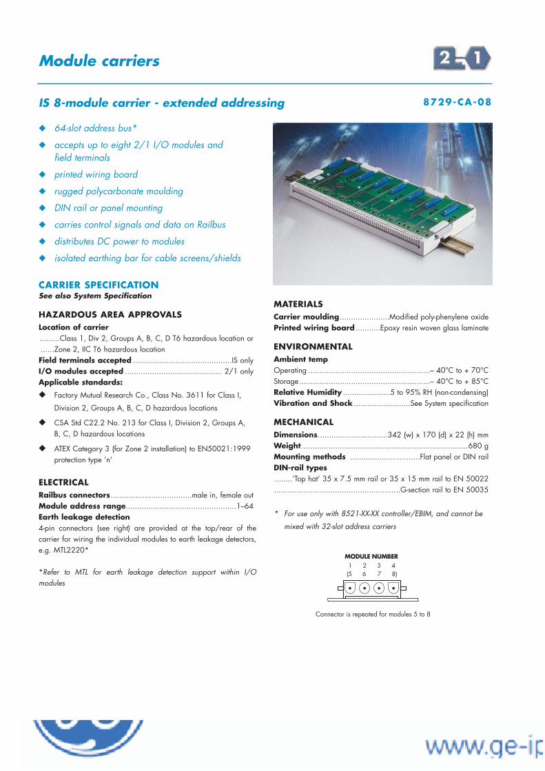
EUROPE (EMEA) Tel: +44 (0)1582 723633 Fax: +44 (0)1582 422283AMERICAS Tel: +1 603 926 0090 Fax: +1 603 926 1899ASIA PACIFIC Tel: +65 487 7887 Fax: +65 487 7997E-mail: [email protected] Web site: www.mtl-inst.com
Jul 2005
Module carriers
IS 8-module carrier - extended addressing 8729-CA-08
64-slot address bus*
accepts up to eight 2/1 I/O modules and field terminals
printed wiring board
rugged polycarbonate moulding
DIN rail or panel mounting
carries control signals and data on Railbus
distributes DC power to modules
isolated earthing bar for cable screens/shields
CARRIER SPECIFICATIONSee also System Specification
HAZARDOUS AREA APPROVALSLocation of carrier.........Class 1, Div 2, Groups A, B, C, D T6 hazardous location or ......Zone 2, IIC T6 hazardous location Field terminals accepted ............................................IS onlyI/O modules accepted ........................................... 2/1 onlyApplicable standards:
Factory Mutual Research Co., Class No. 3611 for Class I,
Division 2, Groups A, B, C, D hazardous locations
CSA Std C22.2 No. 213 for Class I, Division 2, Groups A, B, C, D hazardous locations
ATEX Category 3 (for Zone 2 installation) to EN50021:1999 protection type ‘n’
ELECTRICAL Railbus connectors....................................male in, female outModule address range.................................................1–64Earth leakage detection4-pin connectors (see right) are provided at the top/rear of the carrier for wiring the individual modules to earth leakage detectors,e.g. MTL2220*
*Refer to MTL for earth leakage detection support within I/O modules
MATERIALSCarrier moulding......................Modified poly-phenylene oxidePrinted wiring board ...........Epoxy resin woven glass laminate
ENVIRONMENTALAmbient tempOperating ......................................................– 40°C to + 70°CStorage..........................................................– 40°C to + 85°CRelative Humidity .....................5 to 95% RH (non-condensing)Vibration and Shock .........................See System specification
MECHANICALDimensions...............................342 (w) x 170 (d) x 22 (h) mmWeight..........................................................................680 gMounting methods ...............................Flat panel or DIN rail DIN-rail types........‘Top hat’ 35 x 7.5 mm rail or 35 x 15 mm rail to EN 50022........................................................G-section rail to EN 50035
* For use only with 8521-XX-XX controller/EBIM, and cannot be
mixed with 32-slot address carriers

EUROPE (EMEA) Tel: +44 (0)1582 723633 Fax: +44 (0)1582 422283AMERICAS Tel: +1 603 926 0090 Fax: +1 603 926 1899ASIA PACIFIC Tel: +65 487 7887 Fax: +65 487 7997E-mail: [email protected] Web site: www.mtl-inst.com
June 2004
Module carriers
32-slot address bus*
accepts up to four 2/1 I/O modules and field terminals
printed wiring board
rugged polycarbonate moulding
DIN rail or panel mounting
carries control signals and data on Railbus
distributes DC power to modules
isolated earthing bar for cable screens/shields
CARRIER SPECIFICATIONSee also System Specification
HAZARDOUS AREA APPROVALSLocation of node.........Class 1, Div 2, Groups A, B, C, D T4 hazardous location or ......Zone 2, IIC T4 hazardous location Location of field wiring .........Class 1, Div 1, Groups A, B, C, D T4 hazardous location or ......Zone 1 /Zone 0, IIC T4 hazardous location Field terminals accepted ............................................IS onlyI/O modules accepted ........................................... 2/1 only
ELECTRICAL Railbus connectors....................................male in, female outModule address range.................................................1–32Earth leakage detectionA 4-pin connector is provided at the top/rear of the carrier for wiringthe individual modules to earth leakage detectors, e.g. MTL2220.(Refer to MTL for earth leakage detection support within I/Omodules.)
MATERIALSCarrier moulding......................Modified poly-phenylene oxidePrinted wiring board ...........Epoxy resin woven glass laminate
ENVIRONMENTALAmbient tempOperating ......................................................– 40°C to + 70°CStorage..........................................................– 40°C to + 85°CRelative Humidity .....................5 to 95% RH (non-condensing)Vibration and Shock.................See System specification sheet
MECHANICALDimensions...............................178 (w) x 170 (d) x 22 (h) mmWeight..........................................................................350 gMounting methods ...............................Flat panel or DIN rail DIN-rail types...... ‘Top hat’ 35 x 7.5 mm rail or 35 x 15 mm rail to EN 50022........................................................G-section rail to EN 50035
* Must not be mixed with 64-slot address bus carriers
IS 4-module carrier 8720-CA-04

EUROPE (EMEA) Tel: +44 (0)1582 723633 Fax: +44 (0)1582 422283AMERICAS Tel: +1 603 926 0090 Fax: +1 603 926 1899ASIA PACIFIC Tel: +65 487 7887 Fax: +65 487 7997E-mail: [email protected] Web site: www.mtl-inst.com
June 2004
Module carriers
accommodates one Railbus Isolator
DIN rail or panel mounting
printed wiring board
rugged polycarbonate moulding
32- and 64-slot address capable
CARRIER SPECIFICATIONSee also System Specification
CARRIER MOUNTING MODULERailbus Isolator.....................................................8922-RB-IS
HAZARDOUS AREA APPROVALSLocation of node ...........................................................................Class 1, Div 2, Groups A, B, C, D T4 hazardous location or ......Zone 2, IIC T4 hazardous area
ELECTRICAL Railbus connectors ...................................male in, female outUsable with 32-slot or 64-slot address nodesDC powerDC power for the Railbus Isolator is obtained from the system throughthe multipin Railbus connectors.
MATERIALSCarrier moulding......................Modified poly-phenylene oxidePrinted wiring board ...........Epoxy resin woven glass laminate
ENVIRONMENTALAmbient tempOperating ......................................................– 40°C to + 70°CStorage..........................................................– 40°C to + 85°CRelative Humidity .....................5 to 95% RH (non-condensing)Vibration and Shock.......................See System specification sheet
MECHANICALDimensions (overall) .................93 (w) x 168 (d) x 35 (h) mmWeight (approx.).........................................................195 gMounting methods .................Flat panel (3 fixings) or DIN-railDIN-rail types ..................‘Top hat’, 7.5 x 35 mm or 15 x 35 mm to EN 50022 ............................................................G-section, to EN 50035
Railbus isolator carrier 8723-CA-RB

EUROPE (EMEA) Tel: +44 (0)1582 723633 Fax: +44 (0)1582 422283AMERICAS Tel: +1 603 926 0090 Fax: +1 603 926 1899ASIA PACIFIC Tel: +65 487 7887 Fax: +65 487 7997E-mail: [email protected] Web site: www.mtl-inst.com
June 2004
Module carriers
accommodates one 8920 PSU module
DIN rail or panel mounting
printed wiring board
rugged polycarbonate moulding
32- and 64-slot address capable
CARRIER SPECIFICATIONSee also System Specification
CARRIER MOUNTING MODULESystem Power Supply module ..........................8920-PS-DC
HAZARDOUS AREA APPROVALSLocation of node ...........................................................................Class 1, Div 2, Groups A, B, C, D T4 hazardous location or ......Zone 2, IIC T4 hazardous area
ELECTRICALRailbus connectors .........................................male in, female out(Usable with 32-slot or 64-slot address nodes)
MATERIALSCarrier moulding......................Modified poly-phenylene oxidePrinted wiring board ...........Epoxy resin woven glass laminate
ENVIRONMENTALAmbient tempOperating ......................................................– 40°C to + 70°CStorage..........................................................– 40°C to + 85°CRelative Humidity .....................5 to 95% RH (non-condensing)Vibration and Shock.................See System specification sheet
MECHANICALDimensions (overall) .................93 (w) x 168 (d) x 35 (h) mmWeight (approx.).........................................................195 gMounting methods .................Flat panel (4 fixings) or DIN-railDIN-rail types ..................‘Top hat’, 7.5 x 35 mm or 15 x 35 mm to EN 50022 ............................................................G-section, to EN 50035
IS module power supply carrier 8724-CA-PS
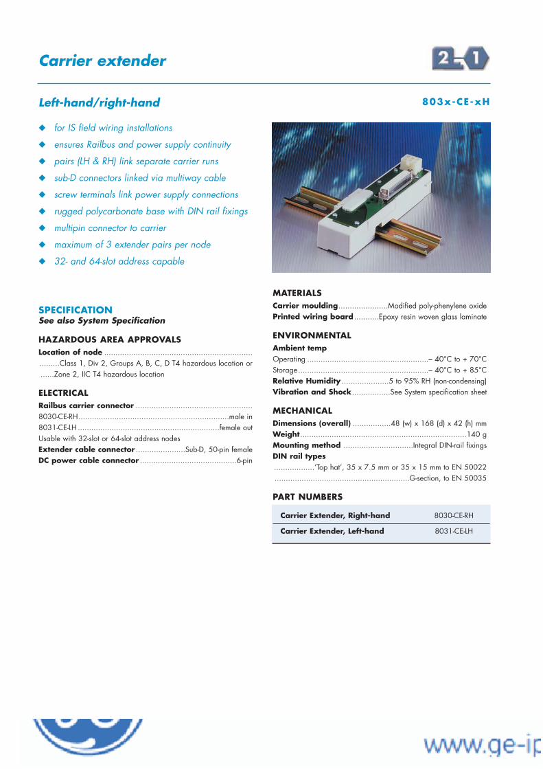
EUROPE (EMEA) Tel: +44 (0)1582 723633 Fax: +44 (0)1582 422283AMERICAS Tel: +1 603 926 0090 Fax: +1 603 926 1899ASIA PACIFIC Tel: +65 487 7887 Fax: +65 487 7997E-mail: [email protected] Web site: www.mtl-inst.com
June 2004
Carrier extender
for IS field wiring installations
ensures Railbus and power supply continuity
pairs (LH & RH) link separate carrier runs
sub-D connectors linked via multiway cable
screw terminals link power supply connections
rugged polycarbonate base with DIN rail fixings
multipin connector to carrier
maximum of 3 extender pairs per node
32- and 64-slot address capable
SPECIFICATIONSee also System Specification
HAZARDOUS AREA APPROVALSLocation of node ...........................................................................Class 1, Div 2, Groups A, B, C, D T4 hazardous location or ......Zone 2, IIC T4 hazardous location
ELECTRICALRailbus carrier connector ....................................................8030-CE-RH...................................................................male in8031-CE-LH ...............................................................female outUsable with 32-slot or 64-slot address nodesExtender cable connector ......................Sub-D, 50-pin femaleDC power cable connector ...........................................6-pin
MATERIALSCarrier moulding......................Modified poly-phenylene oxidePrinted wiring board ...........Epoxy resin woven glass laminate
ENVIRONMENTALAmbient tempOperating ......................................................– 40°C to + 70°CStorage..........................................................– 40°C to + 85°CRelative Humidity .....................5 to 95% RH (non-condensing)Vibration and Shock.................See System specification sheet
MECHANICALDimensions (overall) .................48 (w) x 168 (d) x 42 (h) mmWeight..........................................................................140 gMounting method ...............................Integral DIN-rail fixingsDIN rail types ..................‘Top hat’, 35 x 7.5 mm or 35 x 15 mm to EN 50022............................................................G-section, to EN 50035
PART NUMBERS
Left-hand/right-hand 803x-CE-xH
Carrier Extender, Right-hand 8030-CE-RH
Carrier Extender, Left-hand 8031-CE-LH
EUROPE (EMEA) Tel: +44 (0)1582 723633 Fax: +44 (0)1582 422283AMERICAS Tel: +1 603 926 0090 Fax: +1 603 926 1899ASIA PACIFIC Tel: +65 487 7887 Fax: +65 487 7997E-mail: [email protected] Web site: www.mtl-inst.com
June 2004
Carrier extender cables
Railbus data & power extender cables
for IS field wiring installations
three lengths - 0.35, 0.85 and 1.2 m
sub-D cable connectors
32- and 64-slot address capable
SPECIFICATIONSee also System Specification
HAZARDOUS AREA APPROVALSLocation of node ...........................................................................Class 1, Div 2, Groups A, B, C, D T4 hazardous location or ......Zone 2, IIC T4 hazardous location
ELECTRICALData extender cable connectors .............Sub-D, 50 pin malePower extender cable connectors...............................6-pin
ENVIRONMENTALAmbient tempOperating ......................................................– 40°C to + 70°CStorage..........................................................– 40°C to + 85°CRelative Humidity .....................5 to 95% RH (non-condensing)Vibration and Shock.................See System specification sheet
PART NUMBERS - DATA CABLES
PART NUMBERS - POWER CABLES
PART NUMBERS - CABLE SETS (combining the above)
IS carrier extender cables 80xx-CC-xx
IS Carrier Extension Cable, 0.35m 8011-CC-35
IS Carrier Extension Cable, 0.85m 8012-CC-85
IS Carrier Extension Cable, 1.2m 8013-CC-12
IS Power Extension Cable, 0.35m 8016-CC-35
IS Power Extension Cable, 0.85m 8017-CC-85
IS Power Extension Cable, 1.2m 8018-CC-12
IS Carrier Extension Cable set, 0.35m 8032-CC-35
IS Carrier Extension Cable set, 0.85m 8033-CC-85
IS Carrier Extension Cable set, 1.2m 8034-CC-12

GeneralA field terminal is a replaceableunit for terminating the wiringfrom the field devices. Each I/Omodule requires its own fieldterminal and the correct type isrecommended on the individualI/O module data sheet.
The field wiring is terminated onscrew terminals that can take up to2.5mm2 wire. By wiring virtuallydirectly to the I/O module there isno need for additional patching orterminations.
The field terminal attaches to themodule carrier first; the I/O module is then mounted on it. Apair of multipin connectors linkthe field terminal to the I/Omodule.
EUROPE (EMEA) Tel: +44 (0)1582 723633 Fax: +44 (0)1582 422283AMERICAS Tel: +1 603 926 0090 Fax: +1 603 926 1899ASIA PACIFIC Tel: +65 487 7887 Fax: +65 487 7997E-mail: [email protected] Web site: www.mtl-inst.com
Jan 2007
Field terminals - Screw clamp
!
Fusing & loop-disconnectField terminals are available that contain areplaceable fuse or a “loop-disconnect” linkfor each channel. Fuses have a 2A ratingand, like the links, have a mechanical feature that allows them to be partiallywithdrawn. This provides a break in the fieldwiring loop which assists servicing and faultfinding in the field.
Thermocouple modulesThermocouple modules require specific fieldterminals. The thermocouple modules –8105-TI-TC (4-channel) and 8205-TI-IS (8-channel IS) – each have their own specific field terminal containing a coldjunction compensation sensor. The 8205-TI-IS can also accommodate a remote coldjunction – if used, it occupies one of the eightavailable channels.
RTD modulesThe RTD modules, 8106-TI-RT (4-channel)and 8206-TI-IS (8-channel) use field terminals that are specifically designed toaccommodate 2, 3 and 4-wire connections.The field terminals incorporate diodes thatbecome forward biased if a channelbecomes open circuited - ensuring that otherchannels are not affected by this situation.Similarly, an RTD can be removed from, ornot fitted to, a channel without affecting theoperation. The points where the energisation current enters and leaves thefield terminals are shown by the symbols I+ and I–, respectively, on the appropriatediagrams.
IS field terminalsParticular field terminals are required formodules with built-in IS interfaces, and fieldterminals are coloured blue to mark thisdifference.
Tagging stripA tagging strip is supplied with each terminal (with the exception of the masstermination assemblies). A card is providedfor the user to mark the channel assignmentsfor the field wiring and this is protected by aclear plastic panel.
Mechanical key codingField terminals are an important link in thefield connection process and a mechanicalkeying technique is used to prevent incompatible modules from being connected accidentally to a field circuit. Thisavoids inadvertent damage to I/O modulesand field wiring, and maintains safety inhazardous area applications. It isimplemented in two complementary ways.Rotatable keysA pair of mechanically rotatable keys formpart of the field terminal (see diagrambelow) and these are set by the user duringinstallation to match the fixed key-code (e.g. A 1) of the I/O module that will be fitted onto it. A module with a different key-code cannot then accidentally be fitted onthat field terminal. KeywaysThe four types of field terminal: general purpose, non-incendive, non-arcing andintrinsically safe, have a further pattern ofkeys that make each type unique; modules ofa corresponding type have a matchingkeyway. It is therefore impossible toimplement a potentially hazardouscombination of module and field terminal.
The four types of field terminal can beidentified from the diagram below.

EUROPE (EMEA) Tel: +44 (0)1582 723633 Fax: +44 (0)1582 422283AMERICAS Tel: +1 603 926 0090 Fax: +1 603 926 1899ASIA PACIFIC Tel: +65 487 7887 Fax: +65 487 7997E-mail: [email protected] Web site: www.mtl-inst.com
Jan 2007
Field terminals - Mass Termination Assemblies
Mass Termination AssemblyMass Termination Assemblies (MTAs) offer theuser a number of different ways to terminatefield wiring. Two versions are available, 16-pin (8618-FT-MT) and 44-pin (8619-FT-MT),both of which provide IDC multi-pinconnectors instead of screw terminals.Some standard 1, 2 and 3 metre cables, areavailable from GEF to assist the user; otherscan be made to order; or users can puttogether their own custom cables to suit theirspecific wiring termination requirements.The Mass Termination Assemblies areparticularly useful when legacy systems arebeing replaced and connections must bemade to existing field wiring, junction boxesand marshalling cabinets.Mass Termination Assemblies can also beused to interface to signal conditioning units.For example, with devices that require adrive current above the 1A capability of the 8115-DO-DC discrete output module, the8618-FT-MT can be used to connect to high-current relays*.
Switch/Proximity DetectorWiring PanelThe 8650-FT-PX provides a simple method toterminate up to 32 two-wire field devices. Itis DIN-rail mountable and links to the 8619-FT-MT field terminal using a pair ofready terminated, IDC connector cables. Formaximum convenience, there is alsoprovision for cable screens to be terminatedand grounded.
Mechanical key codingThis feature is available on these terminals.See the previous page for details.
*See Technical Support Note TSN112:“Using the 8115-DO-DC with high-current loads”.
Available from: www.ge-ip.com
· IDC connectors - save wiring time
· Link to high-current output relays
· Quick-connect cable adapters

EUROPE (EMEA) Tel: +44 (0)1582 723633 Fax: +44 (0)1582 422283AMERICAS Tel: +1 603 926 0090 Fax: +1 603 926 1899ASIA PACIFIC Tel: +65 487 7887 Fax: +65 487 7997E-mail: [email protected] Web site: www.mtl-inst.com
Jan 2007
Standard 8602-FT-ST
Fused 8604-FT-FU
THC 8605-FT-TC
RTD 8606-FT-RT
4-wire transmitter 8615-FT-4W
16/30-channel DI 8617-FT-NI
16-pin Mass Termination Assembly 8618-FT-MT
44-pin Mass Termination Assembly 8619-FT-MT
PART NUMBERS
GENERAL PURPOSE FIELD WIRING
THC 8605-FT-TC
RTD 8606-FT-RT
Non-incendive* 8601-FT-NI
Non-incendive, fused* 8603-FT-FU
Non-arcing, standard* 8610-FT-NA
Non-arcing, fused* 8611-FT-FU
4-wire transmitter 8615-FT-4W
16/30-channel DI 8617-FT-NI
16-pin Mass Termination Assembly 8618-FT-MT
44-pin Mass Termination Assembly 8619-FT-MT
Field terminal description Part number
Field terminal description Part number
ZONE 2/DIV2 FIELD WIRING APPLICATIONS
IS, standard 8621-FT-IS
IS, loop-disconnect 8622-FT-IS
IS, 16-channel DI 8623-FT-IS
IS, 8-channel DI, loop-disconnect 8624-FT-IS
IS, THC 8625-FT-IS
IS, RTD 8626-FT-IS
Field terminal description Part number
ZONE 1, 0/DIV 1 (IS) FIELD WIRING APPLICATIONS
Switch/Prox. detector wiring panel 8650-FT-PX
2A Fuse pack (10 in pack) 8401-FU-2A
Loop-disconnect links (10 in pack) 8405-LK-ZE
Description Part Number
ADDITIONAL COMPONENTS
*Refer to 2/2 I/O module data sheets for recommended non-incendive or non-arcing field terminal type in Zone 2 and Division 2 applications.
Field terminals
range of field terminals
standard, fused, loop-disconnect & MTAs
blue moulding for IS field wiring
THC and RTD versions available
tag strip on all screw-clamp field terminals
SPECIFICATIONSee also System Specification
HAZARDOUS AREA APPROVALSLocation of field terminal...Zone 2, IIC, T4 hazardous area or
Class 1, Div 2, Groups A–D, T4 hazardous locationLocation of I/O field wiringFor 860x-FT-xx and 861x-FT-xx...Zone 2, IIC, T4 hazardous ......area or Class 1, Div 2, Groups A–D, T4 hazardous locationFor 862x-FT-IS .........................Zone 0, IIC hazardous area or
Div 1, Groups A–D hazardous location
ELECTRICALRated voltage ..........................................................250V acMaximum current per I/O channel................................3AFuse rating (where fitted) ....................................................2AConductor size ..................................................0.14–2.5mm2
MECHANICALMaterial ....................................Modified Poly-Phenylene OxideDimensions - approx (including tagging strip)8617-FT-NI and 8623-FT-IS................42 (w) x 88 (d) x 61 (h) mmOthers...........................................42(w) x 88 (d) x 39.5 (h) mmWeights (typical - including tagging strip)Unfused type (except THC & RTD) .........................................78g Fused type (including fuses) ..................................................86gTHC type............................................................................70gRTD type ..........................................................................106g8617-FT-NI and 8623-FT-IS (16-channel) ..............................106gSee also datasheets for 8618-FT-MT and 8619-FT-MT

EUROPE (EMEA) Tel: +44 (0)1582 723633 Fax: +44 (0)1582 422283AMERICAS Tel: +1 603 926 0090 Fax: +1 603 926 1899ASIA PACIFIC Tel: +65 487 7887 Fax: +65 487 7997E-mail: [email protected] Web site: www.mtl-inst.com
Jan 2007
Identify terminal type in the table below, then see named diagramfor connections.
Connection diagrams
8601-FT-NI 1
8602-FT-ST 1
8603-FT-FU 1
8604-FT-FU 1
8605-FT-TC 2
8606-FT-RT (2-wire) 3
8606-FT-RT (3-wire) 4
8606-FT-RT (4-wire) 5
8610-FT-NA 1
8611-FT-FU 1
8615-FT-4W 1
8617-FT-NI 6 or 6a†
8618-FT-MT see datasheet
8619-FT-MT see datasheet
8621-FT-IS 1 or 7*
8622-FT-IS 1 or 7*
8623-FT-IS 6
8624-FT-IS 1
8625-FT-IS 8
8626-FT-IS (2 wire) 9
8626-FT-IS (3 wire) 10
8626-FT-IS (4 wire) 11
8650-FT-PX see datasheet
Diagram 2
Diagram 3
Diagram 4
Diagram 5Diagram 1
† Wire as per diagram 6a only when used with 8125-DI-DC or 8127-DI-SE modules.
* Wire as per diagram 7 only when used with 8215-DO-IS module.
Field terminals
Terminal type Diagram No.

EUROPE (EMEA) Tel: +44 (0)1582 723633 Fax: +44 (0)1582 422283AMERICAS Tel: +1 603 926 0090 Fax: +1 603 926 1899ASIA PACIFIC Tel: +65 487 7887 Fax: +65 487 7997E-mail: [email protected] Web site: www.mtl-inst.com
Jan 2007
Connection diagrams
Field terminals - Standard
Diagram 6
Diagram 6a
Diagram 7
Diagram 8
Diagram 11
Diagram 10
Diagram 9

IDC CONNECTOR PINOUTS
When used with the following I/O module types:8101-HI-TX 8102-HO-IP 8103-AI-TX 8104-AO-IP8109-DI-DC 8110-DI-DC 8115-DO-DC 8117-DO-DC8119-VI-05 use this pinout:
When used with I/O module type: 8123-PI-QU
EUROPE (EMEA) Tel: +44 (0)1582 723633 Fax: +44 (0)1582 422283AMERICAS Tel: +1 603 926 0090 Fax: +1 603 926 1899ASIA PACIFIC Tel: +65 487 7887 Fax: +65 487 7997E-mail: [email protected] Web site: www.mtl-inst.com
Nov 2006
Pin Function1 Voltage i/p - Ch 12 Current i/p - Ch 13 Common - Ch 14 NAMUR i/p - Ch 15 Power supply +ve - Ch 26 Power supply +ve - Ch 17 Voltage i/p - Ch 28 Current i/p - Ch 29 Common - Ch 2
10 NAMUR i/p - Ch 211 Common - Ch 112 NAMUR gate control - Ch 113 o/p –ve - Ch 114 o/p +ve - Ch 115 o/p –ve - Ch 216 o/p +ve - Ch 2
Field terminals
16-pin mass termination assembly 8618-FT-MT
!
"
#
$
%
& "
!
16-pin IDC connector termination
IDC alternative for most screw terminal types
use with 8115-DO-DC for high-current relayadapters
provides a choice of field wiring terminations
clip-on protective cover
SPECIFICATIONSee also System Specification
HAZARDOUS AREA APPROVALSField terminal location ......Zone 2, IIC, T4 hazardous area or
Class 1, Div 2, Groups A–D, T4 hazardous locationI/O field wiring location ....Zone 2, IIC, T4 hazardous area or
Class 1, Div 2, Groups A–D, T4 hazardous location
ELECTRICALRated voltage ...........................................................50V ACMaximum current per I/O channel...........................0.75A
MECHANICALMaterial ....................................Modified Poly-Phenylene OxideDimensions - approx....................42(w) x 95(d) x 42*(h) mmWeight .............................................................................44g * with protective cover fitted
CABLE OPTIONS16-way cables, terminated with 16-pin IDC connectors at each end,are available for the 8618-FT-MT.
Description Part number1 metre cable..........................................................8081-FC-102 metre cable..........................................................8082-FC-203 metre cable..........................................................8083-FC-30
See also Technical Support Note TSN112 for details of using this product
with high-current relays.
Notes1. This field terminal cannot be used with the following I/O module types:
8105-TI-TC, 8106-TI-RT Special functionality required e.g. CJC
8121-DI-DC, 8122-DI-DC
8125-DI-DC, 8127-DI-SE
2. AC modules cannot be used with this field terminal because of the 50V AC
voltage rating.
1 2 3 4 5 6 7 8 9 10 11 12 13 14 15 16– + – + – + – + – + – + – + – +
Ch1 Ch2 Ch3 Ch4 Ch5 Ch6 Ch7 Ch8
Insufficient terminals - use 8619-FT-MT

EUROPE (EMEA) Tel: +44 (0)1582 723633 Fax: +44 (0)1582 422283AMERICAS Tel: +1 603 926 0090 Fax: +1 603 926 1899ASIA PACIFIC Tel: +65 487 7887 Fax: +65 487 7997E-mail: [email protected] Web site: www.mtl-inst.com
Nov 2006
USAGE OPTIONS
For further details on choosing and using output relays see Technical Support Note TSN112 “Using the 8115-DO-DC withhigh-current loads”
Field terminals
16-pin mass termination assembly 8618-FT-MT
"#!#!
$%"!!#!
"#!#!
"#!#!
PIN OUT
+ CABLE
+ 16- TO 14-WAY CABLE + HIGH-CURRENT RELAYS

EUROPE (EMEA) Tel: +44 (0)1582 723633 Fax: +44 (0)1582 422283AMERICAS Tel: +1 603 926 0090 Fax: +1 603 926 1899ASIA PACIFIC Tel: +65 487 7887 Fax: +65 487 7997E-mail: [email protected] Web site: www.mtl-inst.com
Jan 2007
32 channel connection
use with 8121/8122 and 8125/8127
use with 8650-FT-PX field terminal
provides a choice of field wiring terminations
clip-on protective cover
SPECIFICATIONSee also System Specification
HAZARDOUS AREA APPROVALSField terminal location ......Zone 2, IIC, T4 hazardous area or
Class 1, Div 2, Groups A–D, T4 hazardous locationI/O field wiring location ....Zone 2, IIC, T4 hazardous area or
Class 1, Div 2, Groups A–D, T4 hazardous location
ELECTRICALRated voltage ...........................................................50V ACMaximum current per I/O channel...........................0.75A
MECHANICALMaterial ....................................Modified Poly-Phenylene OxideDimensions - approx....................42(w) x 95(d) x 42*(h) mmWeight .............................................................................48g * with protective cover fitted
CABLE OPTIONS20- + 24-way cable sets, terminated with IDC connectors at eachend, are available for the 8619-FT-MT. These could be used, forexample, to connect the 8619-FT-MT to the 8650-FT-PX wiring panel.
Description Part number1 metre length set ....................................................8085-FC-102 metre length set ....................................................8086-FC-203 metre length set ....................................................8087-FC-30
Field terminals
44-pin mass termination assembly 8619-FT-MT
IDC CONNECTOR PINOUTS
!
"
#
$
%
& "
!
$
#
&
%
'
!
"
#
$
%
& "
!
$
#
&
%
'
J1 8125/ 8121/Pin 8127 8122
1 Ch 1 Ch 2–2 0V Ch 1–3 Ch 3 Ch 4–4 Ch 2 Ch 3–5 Ch 5 Ch 6–6 Ch 4 Ch 5–7 Ch 7 Ch 8–8 Ch 6 Ch 7–9 Ch 17 Ch 10–
10 Ch 16 Ch 9–11 Ch 19 Ch 12–12 Ch 18 Ch 11–13 Ch 21 Ch 14–14 Ch 20 Ch 13–15 Ch 23 Ch 16–16 Ch 22 Ch 15–17 0V n/c18 Ch 27 n/c19 Ch 28 n/c20 Ch 32 n/c
J2 8125/ 8121/Pin 8127 8122
1 Ch 8 Ch 1+2 Ch 9 Ch 2+3 Ch 10 Ch 3+4 Ch 11 Ch 4+5 Ch 12 Ch 5+6 Ch 13 Ch 6+7 Ch 14 Ch 7+8 Ch 15 Ch 8+9 0V n/c10 Ch 26 Ch 9+11 Ch 24 Ch 10+12 Ch 25 Ch 11+13 Ch 27 Ch 12+14 Ch 28 Ch 13+15 Ch 29 Ch 14+16 Ch 30 Ch 15+17 Ch 31 n/c18 Ch 32 n/c19 0V n/c20 0V n/c21 0V n/c22 0V Ch 16+23 0V n/c24 n/c n/c
Notes:1. 0V pins are all linked only when
the module is fitted.2. Channels 27, 28 and 32 are
common to both J1 and J2
n/c = no connection

EUROPE (EMEA) Tel: +44 (0)1582 723633 Fax: +44 (0)1582 422283AMERICAS Tel: +1 603 926 0090 Fax: +1 603 926 1899ASIA PACIFIC Tel: +65 487 7887 Fax: +65 487 7997E-mail: [email protected] Web site: www.mtl-inst.com
Jan 2007
USAGE OPTIONS
Field terminals
44-pin mass termination assembly 8619-FT-MT
!#!
&#'(
%#)*"+",-
!#!
!#!
PIN OUT
+ CABLE
+ CABLE + 8650 WIRING PANEL

EUROPE (EMEA) Tel: +44 (0)1582 723633 Fax: +44 (0)1582 422283AMERICAS Tel: +1 603 926 0090 Fax: +1 603 926 1899ASIA PACIFIC Tel: +65 487 7887 Fax: +65 487 7997E-mail: [email protected] Web site: www.mtl-inst.com
Jan 2007
Field terminals
Switch/proximity detector wiring panel 8650-FT-PX
)
.
TERMINAL ASSIGNMENTS
) . *
)
/
/ /
/* / /
))
/ /)/
)
)
).
()
()
()
()
()%
()&
()
()
0
1
23
0
1
23
DIMENSIONSin mm
simplified 32-channel field wiring connection
multipin connectors to 8619-FT-MT field terminal
screw terminals for field wiring
DIN-rail mounting
SPECIFICATIONSee also System Specification
HAZARDOUS AREA APPROVALSLocation ..............................Zone 2, IIC, T4 hazardous area or
Class 1, Div 2, Groups A–D, T4 hazardous location
ELECTRICALSystem connectors ........................................20--pin & 24-pinField terminals ......................rising cage-clamp screw terminals Conductor size .................................................0.14–2.5 mm2
Rated voltage ...........................................................50V ACMaximum current per I/O channel...........................0.75AGround terminals ......................................................2 x M4
MECHANICALDIN rail mounting..............................‘T’ section to EN 50022 ...........................................................‘G’ section to EN 50035Weight ...........................................................................390g
CABLE OPTIONS20- + 24-way cable sets to connect with the 8619-FT-MT1 metre length set ....................................................8085-FC-102 metre length set ....................................................8086-FC-203 metre length set ....................................................8087-FC-30

Mass Termination Field Terminal andHigh Current Relay Output
RELAYOUTPUTS
8918-FT-MT
• Mass Termination Connectors Savewiring time to High Current RelayAssemblies.
• Quick Connect Cable Adapter for 6 Ampor 10 Amp Relay Outputs
• Easy Installation, Relay comes completeand ready to snap on to DIN Rail.
• Each Relay includes replaceable Relayand the Din Rail Mounting Assembly
• Adapter connects 8 relays together in asingle package.
High Current Output Capability
New: For discrete field devices that requiremore than the maximum specified current, astandard mass termination field terminal isavailable with a 16-pin connection to allow adirect cable connection to an external panel.Relay output options are available to provideup to 10A per channel. This option greatlysimplifies field wiring.
High current output capability beyond thediscrete output modules’ specified 1 Ampper channel is provided with a masstermination assembly and a direct cableinterface to 6 or 10 Amp relays.
Specifications For Mass TerminationBlockPart No. KVMaximum current 1 Amp per Channel ( 6 Amps per Module )
1 Amp per Cable ( 16 Pin )Voltage Rating 30 VDC Between Non-Connected signalsMax Cable Length 4 metersKey Position Set the Key to match the Discrete Output
Module being Used, For Example : A1Hazardous Area FM Approved Class I, Div 2, Groups
A, B, C & DApprovals Atex 3 G IIC T4
UL US and Canada
Cable: The direct connect cable comes instandard lengths of 1m and 2m. It convertsthe 16 pin output of an 8115 DiscreteOutput module to a 14 pin interface thatconnects directly to the relays. Additionallengths are available if required.
Adapters: There are two different sizeadapters, one for 6 Amp Relays and asecond, larger one for 10 Amp relays. Theseadapters provide a direct connection to therelays from the mass termination block,assuring a quick installation for higher outputpower.

Mass Termination Field Terminal andHigh Current Relay Output
RELAYOUTPUTS
8918-FT-MT
PLC Adapter for Eight 6-Amp Relays -Cable from the Mass termination unit plugsdirectly into the adapter which connectsdirectly to the 8 relays, providing both a costsavings and space savings over conventionalwiring approaches.
Adapters (pictured below) are available forboth the 6 Amp and 10 Amp relays. Choosethe right output for your needs based onrequired current, available panel size andyour budget.
PLC–V8L (10 Amp Relays) PLC-V8 (6 Amp Relays)
SpecificationsDimensions
PLC-V8L w/ 8 10A relays 112mm(w) X 80.3mm(H) X 91.25mm(D)PLC-V8L w/ 8 10A relays 4.4 in. (w) X 3.16 in. (H) X 3.59 in. (D)
PLC-V8 w/ 8 6A relays 49.6mm(w) X 80.3mm(H) X 91.25mm(D)PLC-V8 w/ 8 6A relays 19.6 in. (w) X 3.16 in. (H) X 3.59 in. (D)
Relay for 10 Amp REL-MR-24DC/21-HCInput Data (Coil side)Nominal Input Voltage 24 VDCTypical Input Current 17mATypical response Time 7msTypical Release Time 3msCoil resistance at 20C 1440 Ohms +/-10%Output DataContact Type Single Contact, 1 PDTContact Material AgNIMax Switching Voltage 250 V AC/DCMin Switching Voltage 12 V AC/DCContinuous Current 10 AMax Inrush Current 30A (300ms)Min Switching Current 100 mAMax Pwr Rating, Ohmic Load 250VAC, 4000VAMin Switching Pwr. 1.2W
All relays Assemblies meet the following Certifications
Hazardous Area FM Approved Class I, Div 2, Groups A, B, C & DApprovals Atex 3 G IIC T4 UL US and Canada
Relay for 6 Amp REL-MR-24DC/21Input Data (Coil side)Nominal Input Voltage 24 VDCTypical Input Current 7mATypical response Time 5msTypical Release Time 2.5msCoil resistance at 20C 3390 Ohms +/-10%Output DataContact Type Single Contact, 1 PDTContact Material AgSnOMax Switching Voltage 250 V AC/DCMin Switching Voltage 12 V AC/DCContinuous Current 6 AMax Inrush Current N/AMin Switching Current 10 mAMax Pwr Rating, Ohmic Load 250VAC, 1500 VAMin Switching Pwr. 120 mW
The relays are shipped complete in the DIN Rail mountingpackage and are ready to snap onto the DIN Rail. 8 relaysare jumpered together with the adapter providing anintegrated cable assembly and an easy installation. Therelays are modules that can be replaced in the DIN Railpackage. The 10 Amp relays use a Plug-in Bridge to JumperField Power. This jumper option allows the full 10 Amps perrelay continuous output at 250 VAC when used with the 10Amp Mechanical Relay.
Phoenix Miniature Series Relays
Part No. Model Number Description
2967620 PLC-RSC-24DC/21-HC 10 Amp Mechanical Relay 14mm(8 required)
2967002 PLC-OSC-24DC/24DC/2 3 Amp Solid State Relay (8 required)
2966171 PLC-RSC-24DC/21 6 Amp Mechanical Relay 6.2mm(8 Required)
2299660 PLC-V8L/FLK 14/OUT Large 8 Relay Cable Adapter (10 Amp)
2295554 PLC-V8/FLK 14/OUT 8 Relay Cable Adapter (6 Amp)
2300575 FLK 16/14/DV OUT/100 1m 16 to 14 position cable
2300588 FLK 16/14/DV OUT/200 2m 16 to 14 position cable
2967691 FBST 14-PLC BK Plug-in Bridge 2 Position for 14mm PLC


EUROPE (EMEA) Tel: +44 (0)1582 723633 Fax: +44 (0)1582 422283AMERICAS Tel: +1 603 926 0090 Fax: +1 603 926 1899ASIA PACIFIC Tel: +65 487 7887 Fax: +65 487 7997E-mail: [email protected] Web site: www.mtl-inst.com
June2004
Railbus isolator 8922-RB-IS
Railbus isolator
provides galvanic isolation between Railbus sections
prevents fault-voltage invasions
protects IS field wiring modules
MODULE SPECIFICATIONSee also System Specification
MECHANICALDimensions (approx.) ...............110 (w) x 160 (h) x 42 (d) mmWeight .................................................................345 g (typ.)
HAZARDOUS AREA APPROVALSLocation of module .............................................................................Class 1, Div 2, Group A, B, C, D hazardous location or..................................................Zone 2, IIC T4 hazardous area‘Safe area’ Railbus ............................................Um = 250 VIsolated Railbus ....................................................Un = 18 V
POWER SUPPLIES‘Safe area’ Railbus supply current* .50 mA (max.) @ 12 V IS Railbus supply current* ..................60 mA (max.) @ 12 VPower dissipation within module...................1.2 W (max.)
* Note: DC power for the Railbus Isolator is required from both
sides of the galvanic interface.
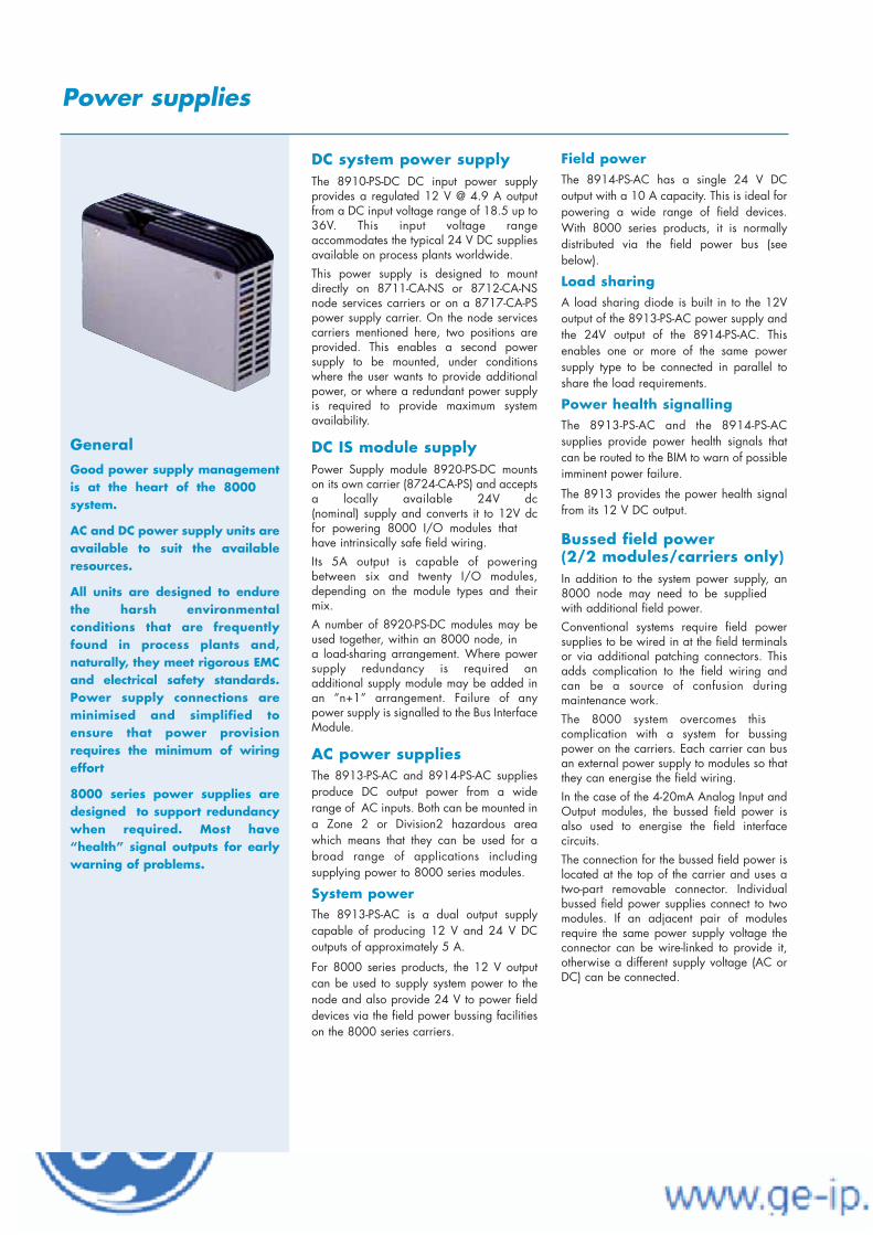
GeneralGood power supply managementis at the heart of the 8000system.
AC and DC power supply units areavailable to suit the availableresources.
All units are designed to endurethe harsh environmentalconditions that are frequentlyfound in process plants and,naturally, they meet rigorous EMCand electrical safety standards.Power supply connections areminimised and simplified toensure that power provisionrequires the minimum of wiringeffort
8000 series power supplies aredesigned to support redundancywhen required. Most have“health” signal outputs for earlywarning of problems.
EUROPE (EMEA) Tel: +44 (0)1582 723633 Fax: +44 (0)1582 422283AMERICAS Tel: +1 603 926 0090 Fax: +1 603 926 1899ASIA PACIFIC Tel: +65 487 7887 Fax: +65 487 7997E-mail: [email protected] Web site: www.mtl-inst.com
June 2004
Power supplies
DC system power supplyThe 8910-PS-DC DC input power supplyprovides a regulated 12 V @ 4.9 A outputfrom a DC input voltage range of 18.5 up to36V. This input voltage range accommodates the typical 24 V DC suppliesavailable on process plants worldwide.This power supply is designed to mountdirectly on 8711-CA-NS or 8712-CA-NSnode services carriers or on a 8717-CA-PSpower supply carrier. On the node servicescarriers mentioned here, two positions areprovided. This enables a second powersupply to be mounted, under conditionswhere the user wants to provide additionalpower, or where a redundant power supplyis required to provide maximum systemavailability.
DC IS module supplyPower Supply module 8920-PS-DC mountson its own carrier (8724-CA-PS) and acceptsa locally available 24V dc (nominal) supply and converts it to 12V dcfor powering 8000 I/O modules thathave intrinsically safe field wiring.Its 5A output is capable of poweringbetween six and twenty I/O modules,depending on the module types and theirmix.A number of 8920-PS-DC modules may beused together, within an 8000 node, ina load-sharing arrangement. Where powersupply redundancy is required an additional supply module may be added inan “n+1” arrangement. Failure of anypower supply is signalled to the Bus InterfaceModule.
AC power suppliesThe 8913-PS-AC and 8914-PS-AC suppliesproduce DC output power from a widerange of AC inputs. Both can be mounted ina Zone 2 or Division2 hazardous areawhich means that they can be used for abroad range of applications includingsupplying power to 8000 series modules.
System powerThe 8913-PS-AC is a dual output supplycapable of producing 12 V and 24 V DCoutputs of approximately 5 A.
For 8000 series products, the 12 V outputcan be used to supply system power to thenode and also provide 24 V to power fielddevices via the field power bussing facilitieson the 8000 series carriers.
Field powerThe 8914-PS-AC has a single 24 V DCoutput with a 10 A capacity. This is ideal forpowering a wide range of field devices.With 8000 series products, it is normallydistributed via the field power bus (seebelow).
Load sharingA load sharing diode is built in to the 12Voutput of the 8913-PS-AC power supply andthe 24V output of the 8914-PS-AC. Thisenables one or more of the same powersupply type to be connected in parallel toshare the load requirements.
Power health signallingThe 8913-PS-AC and the 8914-PS-ACsupplies provide power health signals thatcan be routed to the BIM to warn of possibleimminent power failure.
The 8913 provides the power health signalfrom its 12 V DC output.
Bussed field power (2/2 modules/carriers only)In addition to the system power supply, an8000 node may need to be suppliedwith additional field power.Conventional systems require field powersupplies to be wired in at the field terminalsor via additional patching connectors. Thisadds complication to the field wiring andcan be a source of confusion during maintenance work. The 8000 system overcomes this complication with a system for bussingpower on the carriers. Each carrier can busan external power supply to modules so thatthey can energise the field wiring. In the case of the 4-20mA Analog Input andOutput modules, the bussed field power isalso used to energise the field interface circuits. The connection for the bussed field power islocated at the top of the carrier and uses atwo-part removable connector. Individualbussed field power supplies connect to twomodules. If an adjacent pair of modulesrequire the same power supply voltage theconnector can be wire-linked to provide it,otherwise a different supply voltage (AC orDC) can be connected.

EUROPE (EMEA) Tel: +44 (0)1582 723633 Fax: +44 (0)1582 422283AMERICAS Tel: +1 603 926 0090 Fax: +1 603 926 1899ASIA PACIFIC Tel: +65 487 7887 Fax: +65 487 7997E-mail: [email protected] Web site: www.mtl-inst.com
June 2004
Power supplies
power for 2/2 (general purpose) node
12 V DC output
18.5 - 36V DC input
4.9 A capacity
supports redundancy with second supply
MODULE SPECIFICATION
HAZARDOUS AREA APPROVALSLocation of node ................................................Safe area or ........Class 1, Div 2, Groups A, B, C, D T4 hazardous location or................................................Zone 2 , IIC T4 hazardous areaApplicable standards: Factory Mutual Research Co., Class No. 3611 for Class I,
Division 2, Groups A, B, C, D hazardous locations
ELECTRICALEMC compliance .................. To EN 50081-2 and EN 50082-2..........................................generic emission/immunity standardsElectrical safety . EN 61010-1:1993 and Amendment A2:1995
OUTPUTOutput voltage.................................................12 V dc ± 5%Output current .............................................................4.9 AInput-output isolation.........................50 V ac rms, 720 V dc.............(Continuous working to EN 61010-1, Pollution Degree 2, ......Installation Category 2)Hold-up (on i/p supply failure) ..........................................7 ms...............................................(– 40°C, full load and 22V input)Thermal protection .......................Protected against output s/cSupply health indicator ..................LED (fed from final output)Power-fail signal to BIM (o/p threshold) ..............≤ 8.5 ± 2 V
INPUTInput voltage....................................................18.5–36 V dcEfficiency (at full load)20 V input at 3.6 A ........................................................82.5%24 V input at 3.1 A ........................................................80.0%36 V input at 2.1 A ........................................................80.0%Input connection ................................Two-part, screw terminal......each connection duplicated, 2.5 mm2 max. cable cross-sectionInput protection ...........................Fuse + supply reversal diodePower-fail signal to BIM (i/p threshold).......... ≤19.9 ± 0.5 V
ENVIRONMENTALOperating temperature (no forced ventilation)(60% of full load) ...........................................– 40°C to + 70°COptimum orientation (full load) ........................– 40°C to + 55°CWorst case orientation (full load).......................– 40°C to + 50°CStorage..........................................................– 40°C to + 85°CRelative Humidity .....................5 to 95% RH (non-condensing)Vibration.......................2 g @ 10-100 Hz to BS EN 60068-2-6..............................................................and BS 2011- part 2.1Shock ................10 g, 11 ms pulse width, to BS EN 60068-2-27MTBF @ 50°C external ambient ................................80,000 hrsIngress Protection ...................IP20 to IEC 529/BS EN 60529(tested on power supply carrier with all supply connectors in place)Corrosive atmospheresTo withstand gaseous corrosion level G3 as defined by ISA StandardSP71.04:1995, when protected by a suitable field enclosure.
MECHANICALDimensions (approx.).................42 (w) x 110 (h) x 160 (d) mmCarrier mounting ...............types 8711-CA-NS or 8712-CA-NSWeight..........................................................................775 g
System power supply 8910-PS-DC

EUROPE (EMEA) Tel: +44 (0)1582 723633 Fax: +44 (0)1582 422283AMERICAS Tel: +1 603 926 0090 Fax: +1 603 926 1899ASIA PACIFIC Tel: +65 487 7887 Fax: +65 487 7997E-mail: [email protected] Web site: www.mtl-inst.com
June 2004
power for 2/1 (IS) modules
12 V DC output
24 V DC (nominal) input
5 A capacity
supports load sharing for redundancy
MODULE SPECIFICATION
HAZARDOUS AREA APPROVALSLocation of power supply .................................Safe area or...................Class 1, Div 2, Group A, B, C, D hazardous location..................................................Zone 2, IIC T4 hazardous areaOutput .....................................................Galvanically isolated......................................................Voltage clamped; Un = 18 VApplicable standards: Factory Mutual Research Co., Class No. 3611 for Class I,
Division 2, Groups A, B, C, D hazardous locations
Factory Mutual Research Co., Class No. 3610 for Class I, II, III, Division 1, Groups A - G hazardous locations (IS circuits)
EN 50020:1994 Electrical apparatus for potentially explosive atmospheres, intrinsic safety “i”
EC Directive 94/9/EC (ATEX)
ELECTRICALEMC compliance .................. To EN 50081-2 and EN 50082-2..........................................generic emission/immunity standards.................................EN 61000-3-2:1995 EN 61000-3-3:1995Electrical safety . EN 61010-1:1993 and Amendment A2:1995.............................................................and EN 61131-2:1994
OUTPUTOutput voltage.................................................12 V dc ± 5%Output current ................................................................5 AInput/Output isolation 250 V ac rms(tested at 1500 V ac rms)
INPUTInput voltage....................................................18.5–36 V dcEfficiency (at full load)18.5 V input at 4.1 A ........................................................76%24 V input at 3.3 A............................................................78%36 V input at 2.1 A ........................................................76.5%Input connection ............2-part screw terminal, each duplicatedCable size ......................................................2.5 mm2 (max.)
ENVIRONMENTALOperating temperature (no forced ventilation)(60% of full load) ...........................................– 40°C to + 70°COptimum orientation(full load) ..........................– 40°C to + 55°CWorst case orientation .....................................– 40°C to + 50°CStorage..........................................................– 40°C to + 85°CRelative Humidity .....................5 to 95% RH (non-condensing)Vibration.......................2 g @ 10-100 Hz to BS EN 60068-2-6..............................................................and BS 2011- part 2.1Shock .................10 g, 11 ms pulse width, to BS EN60068-2-27MTBF @ 50°C external ambient ................................80,000 hrsIngress Protection ...................IP20 to IEC 529/BS EN 60529(tested on power supply carrier with all supply connectors in place)Corrosive atmospheres: To withstand gaseous corrosion levelG3 as defined by ISA Standard SP71.04:1995, when protected bya suitable field enclosure.
MECHANICALDimensions (approx.).................84 (w) x 110 (h) x 160 (d) mmCarrier mounting .........................................type 8724-CA-PSWeight........................................................................1290 g
IS module power supply 8920-PS-DC
Power supplies

EUROPE (EMEA) Tel: +44 (0)1582 723633 Fax: +44 (0)1582 422283AMERICAS Tel: +1 603 926 0090 Fax: +1 603 926 1899ASIA PACIFIC Tel: +65 487 7887 Fax: +65 487 7997E-mail: [email protected] Web site: www.mtl-inst.com
Jul 2005
Power supplies
System Power - dual voltage 8913-PS-AC
system & field power for 8000 Process I/O 12 V dc @ 5 A for system power 24 V dc @ 5 A for auxilliary power input voltage 85–264 V ac or 90–264 V dc Zone 2 / Div 2 mounting supports parallel connection for redundancy†
MODULE SPECIFICATIONSee also System Specification
Location of power supply ..................................safe area or..............................................Zone 2, IIC T4 hazardous area or.............Class 1, Div 2, Groups A, B, C, D T4 hazardous location
ELECTRICALEMC compliance ............................To EN 61000-2,3,4,5,6,11........................................................EN 55011/22, EN 55014Electrical safety.................................................To EN 60950
INPUTInput voltage (AC) ............................................85–264 V ac Input frequency (AC).............................................47–65 HzInput voltage (DC) ............................................90–264 V dc Efficiency ...............................................................up to 87 % Connections (Fig. 2) .......................2-part pluggable connectorInput protection................................slow-blow fuse and VDR*
OUTPUTSOutput 1 .....................................................24.7 V dc ± 10%Output 2 .....................................................11.95 V dc ± 5%Output 1 current (see Fig. 1) ...............................5 A (nom.)Output 2 current .............................................................5 AConnections (Fig. 3) .......................2-part pluggable connectorInput-output isolation ..........................................2800 V dcHold-up time (at full rated load) .......................15 ms (typ.)Thermal protection................................reduced output powerSupply health indicator ..................................................LED
POWER-FAIL SIGNALLING - Output 2 only
Threshold to trigger "power-fail" signal .....11.33 V (max.).............................................................................10.30 (min.)Power-fail signal output (open collector)Power supply "OK"......................Low impedance to –ve of o/p 2Power supply "failure" ................High impedance to –ve of o/p 2(Up to 8 power fail signals can be monitored by the 8510-NS-MO module when it is fitted on the 8718-CA-NS carrier.)
† internal load-sharing diode on 12V output only* voltage dependent resistor
60C ambient(optimum attitude - free air)
5 A
2649985
4 A
70C ambient(optimum attitude - free air)
5 A
26412585Input voltage V AC
3.75 A
Input voltage V AC
ENVIRONMENTALOperating ambient temperature...................–40° to +70°CMaximum operating case temperature ...................+80°CStorage temperature ....................................–40° to +100°CRelative humidity..............................93 %, 40°C for 56 days
MECHANICALDimensions (see Fig 4) ......103 (w) x 138 (h) x 113.6 (d) mmMounting methods .........35 mm x 7.5 mm T-section DIN rail
(see also Accessories overleaf)Weight..........................................................................750 g
Figure 1 - Output current de-rating (24 V output only)

EUROPE (EMEA) Tel: +44 (0)1582 723633 Fax: +44 (0)1582 422283AMERICAS Tel: +1 603 926 0090 Fax: +1 603 926 1899ASIA PACIFIC Tel: +65 487 7887 Fax: +65 487 7997E-mail: [email protected] Web site: www.mtl-inst.com
Jul 2005
Power supplies
System Power - dual voltage 8913-PS-ACcont inued
TERMINAL ASSIGNMENTSInput connector screw terminals
Figure 2 - AC input power
Output connector screw terminals
Figure 3 - DC output power
ACCESSORIESHeavy duty DIN rail mounting kit† ...........................8413-FK-DNSurface panel mounting kit .......................................8414-FK-SU† For larger amplitude vibration environments
1 2 3 4 5 6 7 8 9 10 11
Figure 4 - Outline and fixing dimensions
Terminal Des. Description1 Protective earth
2 N Input neutral
3 L Input live
Terminal Des. Description
1 Protective earth
2 + Output 1 + ve
3 + Output 1 + ve
4 – Output 1 – ve
5 – Output 1 – ve
6 + Output 2 + ve
7 + Output 2 + ve
8 – Output 2 – ve
9 – Output 2 – ve
10 Aux. Power fail signal
11 Protective earth
24 V DC
12 V DC
Applicable standards:• Factory Mutual Research Class No. 3600/3611 for Class I,
Division 2, Groups A, B, C, D hazardous locations• ATEX Directive 94/9/EC Category 3 - II 3 G• CENELEC standard EN50021:1999 EEx n A II T4• CSA International - Class 2258 02
APPROVALS
Authority Standards Certificate No.FM No. 3600/3611 3011821
TÜV EN50021 TÜV01ATEX1774X
CSA 2258 02 1368864

EUROPE (EMEA) Tel: +44 (0)1582 723633 Fax: +44 (0)1582 422283AMERICAS Tel: +1 603 926 0090 Fax: +1 603 926 1899ASIA PACIFIC Tel: +65 487 7887 Fax: +65 487 7997E-mail: [email protected] Web site: www.mtl-inst.com
Jul 2005
Power supplies
Field power 8914-PS-AC
power for wide range of Zone 2/Div 2 mounted equipment
field power for 8000 Process I/O
24 V dc @ 10 A for field power
input voltage 85–264 V ac or 90–264 V dc
Zone 2 / Div 2 mounting
supports parallel connection for redundancy
MODULE SPECIFICATIONSee also System Specification
HAZARDOUS AREA APPROVALSLocation of power supply .................................safe area or.............................................Zone 2, IIC T4 hazardous area or............Class 1, Div 2, Groups A, B, C, D T4 hazardous locationApplicable standards:• Factory Mutual Research Co., Class No. 3611 for Class I,
Division 2, Groups A, B, C, D hazardous locations• ATEX Category 3 for Zone 2
ELECTRICALEMC compliance ...........................To EN 61000-2,3,4,5,6,11.......................................................EN 55011/22, EN 55014Electrical safety ................................................To EN 60950
INPUTInput voltage (AC) ............................................85–264 V ac Input frequency (AC).............................................47–65 HzInput voltage (DC) ............................................90–264 V dcEfficiency ..............................................................up to 87 % Connections (Fig. 2) ......................2-part pluggable connectorInput protection ...............................slow-blow fuse and VDR*
OUTPUTOutput............................................................24 V dc ± 10%Output current (see also Fig.1).........................10 A (nom.)Connections (Fig. 3) ......................2-part pluggable connectorInput-output isolation ........................................2800 V DCHold-up time (at full rated load) ......................15 ms (typ.)Thermal protection ...............................reduced output powerSupply health indicator .................................................LED
POWER-FAIL SIGNALINGThreshold to trigger "power-fail" signal ......23.3 V (max.)...........................................................................22.0 V (min.)Power-fail signal output (open collector)Power supply "OK" .............................Low impedance to groundPower supply "failure"........................High impedance to ground(Up to 8 power fail signals can be monitored by the 8510-NS-MO
module when it is fitted on the 8718-CA-NS carrier.)
*voltage dependent resistor
ENVIRONMENTALOperating ambient temperature ..................–40° to +70°CMaximum operating case temperature ..................+80°CStorage temperature ...................................–40° to +100°CRelative humidity .............................93 %, 40°C for 56 days
MECHANICALDimensions (see Fig 4) ......103 (w) x 138 (h) x 113.6 (d) mmMounting methods .........35 mm x 7.5 mm T-section DIN rail
(see also Accessories overleaf)Weight .........................................................................750 g
Figure 1 - Output current de-rating
60C ambient(optimum attitude - free air)
10 A
2649985
8 A
70C ambient(optimum attitude - free air)
26416585Input voltage V AC
7.5 A
Input voltage V AC
10 A

EUROPE (EMEA) Tel: +44 (0)1582 723633 Fax: +44 (0)1582 422283AMERICAS Tel: +1 603 926 0090 Fax: +1 603 926 1899ASIA PACIFIC Tel: +65 487 7887 Fax: +65 487 7997E-mail: [email protected] Web site: www.mtl-inst.com
Jul 2005
Power supplies
Field power 8914-PS-ACcont inued
TERMINAL ASSIGNMENTSInput connector screw terminals
Figure 2 - AC input power
Output connector screw terminals
Figure 3 - DC output power
ACCESSORIESHeavy duty DIN rail mounting kit† ...........................8413-FK-DNSurface panel mounting kit .......................................8414-FK-SU† For larger amplitude vibration environments
1 2 3 4 5 6 7 8 9 10 11
Figure 4 - Outline and fixing dimensions
Terminal Des. Description1 Protective earth
2 N Input neutral
3 L Input live
Terminal Des. Description
1 Protective earth
2 + Output + ve
3 + Output + ve
4 – Output – ve
5 – Output – ve
6 + Output + ve
7 + Output + ve
8 – Output – ve
9 – Output – ve
10 Aux. Power fail signal
11 Protective earth
Applicable standards:• Factory Mutual Research Class No. 3600/3611 for Class I,
Division 2, Groups A, B, C, D hazardous locations• ATEX Directive 94/9/EC Category 3 - II 3 G• CENELEC standard EN50021:1999 EEx n A II T4• CSA International - Class 2258 02
APPROVALS
Authority Standards Certificate No.FM No. 3600/3611 3011821
TÜV EN50021 TÜV01ATEX1774X
CSA 2258 02 1368864

Feb 2003EUROPE (EMEA) Tel: +44 (0)1582 723633 Fax: +44 (0)1582 422283AMERICAS Tel: +1 603 926 0090 Fax: +1 603 926 1899ASIA PACIFIC Tel: +65 487 7887 Fax: +65 487 7997E-mail: [email protected] Web site: www.mtl-inst.com
Power Supplies
Node Services Power Supply Monitor for 8521 Controllers 8410-NS-PS
15.8104
89
Power ON indicator
power supply status monitoring
signals supply failure(s)
monitors all 2/2 and 2/1 power supplies
Zone 2/Div 2 mounting
mounts on 8750-CA-NS carrier
The Power Supply Monitor can monitor the health of supplies pow-ering an 8000 node and signal the controller/EBIM in the eventof one, or more, of them failing. The module can receive powersupply status signals from up to six external supplies and can alsomonitor the status of 8920-PS-DC supplies which power the intrinsi-cally safe (2/1) I/O modules.Where power supply redundancy is employed, the module enablesfailed power supplies to be identified and replaced without interfer-ence to the process. The module itself may be removed andreplaced in a Zone 2/ Div 2 hazardous area without gas clearance.
MODULE SPECIFICATIONSee also System Specification
HAZARDOUS AREA APPROVALSLocation of monitor module..............................Safe area or..................................................Zone 2, IIC T4 hazardous area.........or Class 1, Div 2, Groups A, B, C, D T4 hazardous locationApplicable standards: Factory Mutual Research Co., Class No. 3611 for Class I,
Division 2, Groups A, B, C, D hazardous locations
CSA Std C22.2 No. 213 for Class I, Division 2, Groups A, B, C, D hazardous locations
ATEX Category 3 (for Zone 2 installation) to EN50021:1999 protection type ‘n’
INPUTS (VIA CARRIER)Number of inputsFrom external 2/2 power supplies ............................................6Via Railbus from 8920-PS-DC power supplies.............................1Power supplies "OK" ......................low impedance to groundPower supply "failure" ..................high impedance to ground
ELECTRICALRailbus (12V) current .................................................5 mA (typ.)...........................................................................10 mA (max.)
LED INDICATORPWR (i.e. Railbus supply present)
ENVIRONMENTALAmbient tempOperating, .....................................................– 40°C to + 70°CStorage..........................................................– 40°C to + 85°CRelative Humidity .....................5 to 95% RH (non-condensing)Vibration and Shock .........................See System specification
MECHANICALMounting method..............................(captive x2) screw fixingWeight (approx.) ...........................................................75 g
DIMENSIONS (MM)


PAC8000 Workbench
Configuration Guide

2
Contents
PAC8000 Workbench Overview......................................3
Basics for Quoting the PAC8000 Workbench .............3
Choose the Controllers ................................................................................................... 3 I/O Points Required .......................................................................................................... 4 Serial BIMs .......................................................................................................................... 5 Disaster Recovery............................................................................................................. 5 GlobalCare.......................................................................................................................... 5
PAC8000 Workbench Part Numbers.............................6
PAC8000 Workbench without GlobalCare................................................................. 6

3
Title 1
PAC8000 Workbench Overview The PAC8000 Workbench is the configuration and programming software for the PAC8000 Controllers and Ethernet Bus Interface Modules (EBIMs). It provides our customers with the software necessary to configure the I/O modules, build control logic in process function blocks as well as the IEC languages, and then download and troubleshoot the logic in either a process simulator or the controller hardware. The PAC8000 Workbench is sold based on I/O counts. More details on I/O count definitions will be given later in this guide. The Workbench can also be sold as either a standalone component or as part of a PPS system.
Basics for Quoting the PAC8000 Workbench To quote the PAC8000 Workbench there are some basic things you will need to know about your customer’s application. The key information is the type of controllers that will be used as well as the amount of I/O that will be included in the project. Note that a project may contain more than one controller and the Workbench can be used for multiple projects, so you need to understand the size of the maximum project the customer will want to configure in the Workbench.
Choose the Controllers The PAC8000 Workbench supports different controller types:
The Hybrid Controller allows the customer to write logic in both Advanced Function Blocks (PID and Motor Control) as well any of the IEC 61131-3 languages.
The Process Controller allows the customer to write logic in Advanced Function Blocks (PID and Motor Control) but NOT the IEC 61131-3 languages.
The Logic Controller allows the customer to write logic in the IEC 61131-3 Languages, but NOT the Advanced Function Blocks (PID and Motor Control).
The EBIM is a remote I/O interface and supports no programming languages.
The SafetyNet controller is SIL2 certified and support writing logic in a reduced set of the IEC 61131-3 languages.

4
Thus, the languages supported by the various controller types are:
Languages Supported Controller Type
Adv. Function Blocks IEC 61131-3
Hybrid X X
Process X
Logic X
Ethernet BIM
SafetyNet X
Workbenches licenses exist for each of the above controller types. Note, though, that a Hybrid Workbench can be used to configure any controller type EXCEPT SafetyNet while a SafetyNet and Hybrid Workbench can configure any controller type. A Process Workbench can only configure Process Controllers. Similarly a Logic Workbench can only configure Logic Controllers and an Ethernet BIM Workbench can only configure EBIMs. However, any Workbench type can be used to configure the EBIM. The types of Workbenches and the controllers they can be used to configure/program are as follows:
Supported Controller Types Workbench Type
Hybrid Process Logic EBIM SafetyNet
Hybrid X X X X
Process X X
Logic X X
Ethernet BIM X
SafetyNet Logic X X
SafetyNet Logic & Hybrid X X X X X
Runtime Edition DL DL DL DL DL
where “DL” indicates download only capability.
I/O Points Required The Workbench is sold based on the maximum number of I/O points that will be configured in a project (one or more controllers). Three (3) different I/O count options are offered: 3000, 5000, and 5000+. Note that this I/O point count DOES NOT apply to SafetyNet only Workbench. However, there are versions of the Workbench that include SafetyNet as well as an I/O count limited version of the standard Workbench. The definition of an I/O point in the Workbench is a physical I/O point wired to an 8000 Process I/O module; internal and other non-I/O module tags are not counted.

5
Serial BIMs If the customer requires a serial BIM, then a configuration cable is required in addition to the stand-alone I/O Configuration software that is included on the PAC8000 Workbench CD. The cable can be ordered separately, or as part of a bundle that includes both the software and the cable. In terms of the I/O counts, a serial BIM does not count toward the total I/O used in a project. Note also that if only serial BIMs are required, there is no need to buy the Workbench. In such cases the 8000 Process I/O Configuration Software is sufficient.
Disaster Recovery There is a Workbench available to program each controller type; however, there are times when a customer may not possess the Workbench. This is usually when an integrator has created and installed the application for the customer and does not want the customer making changes. However, the customer may need to troubleshoot logic or download an existing program if problems arise. The Workbench Runtime Edition is available to fill this need.
GlobalCare GlobalCare is automatically added to the quote/order by the system based on the customer’s current GlobalCare contract.

6
PAC8000 Workbench Part Numbers PAC8000 Workbench without GlobalCare Part Numbers Part Description
I/O Configuration Software
8455-SW-CF 8000 Process I/O Configuration Software (Serial cable included)
8456-SW-CF 8000 Process I/O Configuration Software (Software only)
8460-CA-CF 8000 Process I/O Configuration Cable
Hybrid Workbench
8459-HC-30 Hybrid Workbench 3000 I/O
8459-HC-50 Hybrid Workbench 5000 I/O
8459-HC-00 Hybrid Workbench 5000+ I/O
Process Workbench
8459-PC-30 Process Workbench 3000 I/O
8459-PC-50 Process Workbench 5000 I/O
8459-PC-00 Process Workbench 5000+ I/O
Other Workbench
8459-LC-MT Logic Workbench
8459-EB-MT Ethernet BIM Workbench
8459-RT-MT Workbench Runtime Edition
SafetyNet Workbench
8841-LC-MT SafetyNet Logic Workbench
8841-HC-30 Hybrid Workbench 3000 I/O plus SafetyNet
8841-HC-50 Hybrid Workbench 5000 I/O plus SafetyNet
8841-HC-00 Hybrid Workbench 5000+ I/O plus SafetyNet

7
©2009 GE Intelligent Platforms For Internal Use Only
All Rights Reserved


GE Intelligent Platforms
PAC8000 Hybrid Workbench 8459-HC-MT Powerful software for advanced control strategies PAC8000 Strategy Builder for process control applications IEC 61131-3 software for logic control applications Project management tools Network configuration & administration Tagname-based configuration - simplifying system configuration Auto-tagname generation Control strategy development and simulation tools Online configuration and reconfiguration Peer to peer communications Remote data table for mapping Modbus® devices Import/export utilities and reports Project back-up and restore
Overview The PAC8000 Hybrid Workbench is an integrated project development environment used to create executable program files for download to a PAC8000 Hybrid, Process or Logic Controller, or to configure an 8000 Process I/O Ethernet BIM (EBIM). It is the most comprehensive of all of the Workbench tools as it combines the full functionality of the PAC8000 Process Control and PAC8000 Logic Control Software in a single development tool. The Workbench is used to centralize project engineering by enabling a user to create an instrument index, coordinate I/O database configuration and control strategy development. It configures the control logic and generates an export database to create the operator (HMI) database. It also provides a client-server implementation that enables multiple engineers to work on the same project. PAC8000 Process Control PAC8000 Process Control software is an open, easy-to-use process control engineering and management solution that delivers comprehensive, distributed control functionality. PAC8000 Process Control is a fully integrated advanced process control and instrument engineering system offering configuration tools, modeling, simulation, troubleshooting utilities, project drawing management and self-documentation. It is a robust solution that provides the flexibility to configure control systems ranging from a few loops to thousands of points. A flexible, scalable design allows cost effective system expansion. In addition, the system's extensive use of industry standards simplifies integration with other applications. PAC8000 Logic Control PAC8000 Logic Control software is the complete tool kit for creating IEC61131-3 programs. The Workbench fully supports the five IEC61131-3 automation languages - Ladder Diagram (LD), Sequential Function Chart (SFC), Function Block Diagram (FBD), Structured Text (ST), Instruction List (IL) - plus Flow Chart and is used to develop, download, simulate, debug, monitor, and edit application programs. PAC8000 Logic Control lets you mix programming languages in the same project. Its true
Windows interface will guide you through development of your project. The Workbench Simulator will test your programs before startup. Then use the Workbench to dynamically view programs as they run in real-time and make changes on-the-fly. PAC8000 Ethernet® BIM (EBIM) In a PAC8000 Control system, an Ethernet BIM (EBIM) system can be used as remote I/O to a PAC8000 system controller. In this case, all remote EBIM nodes would be configured as if part of a local I/O system, providing a single integrated configuration of all I/O nodes in the system, whether local or remote. In keeping with its ability to maintain operations on a continuous basis, a redundant EBIM is also capable of receiving a firmware upgrade while in the field. The Workbench provides all the necessary tools to support the PAC8000 Ethernet BIM. I/O Configurator The I/O Configurator is a flexible tool that can communicate directly with the I/O modules. It has a number of functions, ranging from updating the module firmware, through providing the user with in-depth information about the hardware, to setting up the conditions the user will require of the system if the equipment has to go into failsafe mode. Microsoft® Windows® Environment Designed using a Microsoft Windows Explorer paradigm, the Workbench provides a powerful and flexible framework that significantly reduces project implementation and maintenance costs. In addition to working with an easy-to-use hierarchy of objects and folders, capabilities such as drag-and-drop, right mouse click support and context sensitive help inherent within the Workbench make developing, testing and maintaining automation projects easy and straightforward. The Workbench also provides system-wide security allowing for multiple levels of access to the control system.

PAC8000 Hybrid Workbench 8459-HC-MT
The PAC8000 Hybrid Workbench is an integrated project development environment that centralizes and coordinates project engineering including instrument index, I/O database configuration and control strategy development. It is a client-server implementation allowing multiple engineers to work on the same project. In addition to the extensive control software, the Workbench also provides significant tools for your control system, including I/O Configurator, Program Compiler, Downloader, Remote Data Table Builder for Modbus, Tag Builder, Network Configurator and a Peer-to-Peer table builder. With this extensive range of tools, the Workbench is much more than a development system, it also provides overall system management. Comprehensive tools The PAC8000 Hybrid Workbench provides process and IEC61131-3 programming for regulatory and discrete control.
The Workbench configures the control strategy or logic and generates an export table that is used to create the operator interface database for all popular HMI packages. The system eliminates expensive, laborious and sometimes error-prone manual engineering work typically required during control projects. Manual generation of bill of materials, control strategy diagrams, and operator interface requirements are abolished. Repetitive programming of control strategies for advanced control is no longer necessary. Similarly, eliminating the repetitive input of system information significantly reduces errors and configuration time. All Workbench activity is centered on a project(s) that is created to address a control need. Controllers are selected and assigned to the project after it has been created. PAC8000 Hybrid Control enables you to remotely manage HART® based field instruments. PAC8000 controllers can pass HART® information from smart field devices to a separate PC workstation running asset management software, such as
Applied Systems Technologies' Cornerstone Software or Emerson's Asset Management Software. Network configuration tool The Workbench's Network Configuration Tool can be used to configure your entire plant network, setting up and maintaining TCP/IP addresses for all devices on the network. After the network is setup, the Workbench is used to monitor and maintain the devices on the network. Each controller, including redundant controllers, needs IP addresses, MAC addresses and node numbers. If the MAC addresses are unknown, they can be found through the Network Configuration tool. Then the Network Configurator can be used to manage the assignment of IP addresses to the controllers. It also provides additional information about each controller that has been configured, such as whether it is a single or redundant controller and the status of both Ethernet LANs. Tagname based system All variables are referred to by tagname, providing a descriptive reference to all variables throughout the system, replacing the need to reference register addresses. The Logic Workbench models a process system input/output with the assignment of module and point destinations. Using a predetermined template, this task is accomplished as a simple "fill in the blanks" procedure and builds the project I/O configuration database. Tag import utility The Tag Import Utility can be used to import a tag list that is already defined in a spreadsheet format. The utility imports a .csv, tab or space separated file directly into the Workbench, saving the need to manually recreate this information if it already exists. Peer to peer capability The peer-to-peer capability allows data from a controller to be used on the network. This takes advantage of the high-speed peer-to-peer communications of the Ethernet network, resulting in more efficient control processing. Peer-to-peer data is setup with tag name assignment, with the tag names being available to all controllers on the network. Assigning peer-to-peer data is easy, all you need to do is simply drag and drop Tagnames from another project or controller to the current controller. Standardized reports All databases are MSDE (Microsoft Data Engine) databases, which are fully SQL compliant and can be readily shared throughout the system. This design enables many standardized reports to be readily generated, including a list of Assigned I/O, Available I/O, Unassigned Points, Factory Acceptance Test status, Point Overview report that lists transducer information for all the tags in the systemTagname for HMI (which returns the information located on the HMI tab of the Project Tags window) and Tagname Index (which returns the information located on the I/O Definition tab of the Project Tags). These reports simplify the overall management of the project.

PAC8000 Hybrid Workbench 8459-HC-MT I/O Configurator I/O modules connected to a controller must be configured to permit operation. The controller needs to be told the identity of each I/O module fitted and values of relevant parameters. Modules are added by a simple drag and drop process. Each module has its own set of parameters and these appear with default values when the module is first added to the system. These can then be edited individually to specify the required values and then tagnames are assigned to each I/O point. Failsafe values can be defined to assure that the modules operate safely if there is a system interruption. Dynamic data Real-time data is available on-screen. The viewable data includes primary variables as well as status parameters. This can be refreshed continually or when the operator requires a screen refresh. Configuration upload Configuration data already contained in a controller can be uploaded to the Workbench. This can be saved as a PC file and copied to other Controllers. PC files that were created for earlier reversions of the controller firmware can also be opened and edited for use with the latest versions of the controller. Simple tabbed pages The right hand side of the screen contains information on any item that is highlighted in the navigation tree to the left. For example, with the network icon selected, three tabbed pages of information are available. These pages define and describe the network protocol, the controllers that are attached to the network and the details of the project contained in the overall configuration file. The Control System Each downloaded application is a complete distributed application running on the target controller. Multiple applications, running on separate controllers, can be linked together using the peer-to-peer tool, which identifies tagnames for use across the network. This data exchange mechanism provides a very efficient way of sharing information between multiple controllers. Project backup and restore You can create a backup file of your project at any time. This useful feature enables you to save your application in a known state, and if necessary, restore the project to that state. You can import and export resources from one project to another, enabling you to re-use prior work. If the results of importing or exporting resources are unsatisfactory, you can choose to restore the project. Downloader The Workbench Downloader is used to download the firmware and control strategy to the controller. With Redundant Controllers, strategy changes can be downloaded to a backup controller without disrupting control in the primary controller. When the download is complete, the backup controller will take over control and update the primary controller with the changes. Control can revert back to the primary controller after these changes are incorporated. Downloading to a simplex controller can be done on-line and without initializing data, the new strategy starting on the next execution cycle.
Remote data table builder for Modbus import The remote data table is used for connecting to remote Modbus master or Modbus slave devices. Tagnames are assigned to these devices, which are then included in the control strategy. An example of a remote Modbus device is a Modbus TCP compliant H1 Linking device that could be used to bring Foundation Fieldbus H1 data into the control system.

PAC8000 Hybrid Workbench 8459-HC-MT
PAC8000 Process Control Software PAC8000 Process Control Software consists of two integrated components; the Instrument Index and the PAC8000 Strategy Builder. Instrument Index The Instrument Index is used to model the process system’s input/output by assigning controller, module and point destinations. Using a predetermined template, this task is accomplished as a simple "fill in the blanks" procedure. The Instrument Index uses this information to build the I/O configuration data file. This data file will subsequently be used to cross-link the point attributes to the algorithms on the process control diagrams. PAC8000 Strategy Builder Process control logic diagrams are developed using the PAC8000 Strategy Builder. The control strategy is built by selecting the appropriate blocks, assigning symbolic tags, and then connecting the blocks with analog or digital lines, using standard drawing forms and commands. SAMA style drawings define all the functions and parameters that generators, pulse controllers, sequencers, bumpless transfers, PID and other standard function blocks. To further reduce development time template diagrams can be created and reused within the current project or another future project. For example, a cascade loop can be created and saved for repetitive use to generate additional control loops. When the drawing model is completed, the project diagrams are cross-linked with the I/O database to create: Comprehensive control system engineering
documentation. Advanced control strategies. Operator interface database, alarms and faceplates. System maintenance tools.
There is no need to review function block codes, re-enter tags, generate spare parts listings, or match control logic to the operator interface. This allows the user to concentrate on designing control strategies and eliminate the repetitive tasks. Project Components In addition to these key design features, PAC8000 Process Control has a wealth of tools and features that simplify the
management of the project and provide easy to use interfaces for the user. Comprehensive Self-Documentation PAC8000 Process automatically generates as-built system documentation including I/O configuration reports, cross reference analysis, bill of materials, instrument index, system start-up, maintenance information, and wiring diagrams. The instrument index provides instrument details such as manufacturer, model number, group number, shift and day log, panel
wiring information including panel in/out terminal block and panel in/out position, and field wiring information including cable color, size and type. Advanced Control Strategies The system automatically configures control solutions from straight-forward single loops to advanced control strategies. PAC8000 Process Control algorithms provide the logic and analytic functions for complex control strategies such as feed forward, cascade, and multi-variable control. Functions are provided for easily configuring biased multi-output loops as found in steam and water header pressure control. The system automatically accounts for different device capacities, devices in service, and devices in automatic mode. Adaptive tuning functions for PID control is supported. Two and three state device drivers provide the functionality for motor and valve operations with failure alarms, local and remote operation, and interlocks. Sequential step functions with interlocks and first out functionality are easily configured. The system provides I/O and point alarm status.
On-line Maintenance, Tuning and Troubleshooting Savings in time and system costs are not limited to initial development and start-up. The system provides suggestive tuning capabilities, on-line and off-line control configuration, and intelligent control schematics from which the system can be modified and tuned. PAC8000 Process Simulator The PAC8000 Process Simulator allows the animation of control diagrams with either simulated data or live, real-time process data. The Simulator is also used for tuning and operator control purposes. I/O diagnostic tags are provided for the operator interface for troubleshooting assistance. Verification of control loop integrity and troubleshooting loop problems can be accomplished quickly and efficiently.

PAC8000 Hybrid Workbench 8459-HC-MT
PAC8000 Logic Control Software IEC 61131-3 languages PAC8000 Logic Control Software is 32-bit software for distributed control applications. It supports all five IEC 61131-3 languages: Ladder Diagram (LD), Structured Text (ST), Instruction List (IL), Sequential Function Chart (SFC) and Function Block Diagram (FBD), plus the Flow Chart (FC) language. The workbench is used initially to create and edit the control code and may also be used later for simulation, debugging and on-line monitoring. The code created in the workbench is then downloaded to the PAC8000 Controller. Language options The Ladder Diagram (LD) is one of the PAC8000 familiar methods of representing logic equations and simple actions. Contacts represent input arguments and coils represent output results. Each block in the selection list has a description text.
The Structured Text (ST), is a high level structured language with a syntax similar to Pascal but more intuitive to the automation engineer. This language is mainly used to implement complex procedures that cannot be easily expressed with graphical languages. The ST text editor guides the user to the correct syntax and punctuation and provides the best validation and programmer assistance facilities. The Sequential Function Chart (SFC) language divides the process cycle into a number of well-defined steps, separated by transitions. The Workbench fully supports graphical Function Chart programming, which is familiar to many engineers. The Instruction List (IL) is a low-level language, similar to the simple textual PLC languages. IL is a register-level programming language. PAC8000 Logic Control has a set of more than 60 IEC functions and function blocks. Users can enlarge this set by writing functions and function blocks in the LD, FBD, ST, and IL languages.
The Flow Chart is an easy to read decision diagram where actions are organized in a graphic flow. The Flow Chart Editor has full support for connectors and sub-programs. Function Block Diagram (FBD) is a graphical language which allows the user to build complex procedures by taking existing function blocks from the Workbench library, and wiring them together on screen. The FBD editor allows manual input of variables. The diagrams can be zoomed to view the whole diagram or specific areas in more detail. User can mix LD and FBD programming in the same chart. The development process begins with the division of a project into several PLC Loops, also called Resources, identifying their host hardware platforms, and defining the links between them. The physical division of a project is represented by configurations and communications networks. A Configuration represents a hardware platform which contains a single resource. Program development process A resource contains several programming units called Program Organization Units (POUs). POUs can be programs, functions or function blocks. Programs can be described in any of the five IEC 61131-3 languages plus Flow Chart.
Linking variables to I/O channels Before defining the project code, the I/O is defined in the Workbench in the form of a tag database, which identifies the I/O channels and their respective field devices. Once a device is selected, a simple mouse-click 'connects' a variable to a channel. The Build To validate the project, the project code must be built. This step is also very useful for syntax checking; all detected errors can be easily located with a simple mouse-click. The generated code is fully publicly documented supported. The code generator produces the code for each resource. Logic Control Strategy Simulation Simulation enables the project code to
be tested without the need for any hardware to be attached. Each resource can be executed cycle by-cycle, and various system variables, such as the cycle time, can be monitored or forced. For debugging with real platforms, or to perform maintenance operations on 'live' systems, changes can be downloaded on-line without stopping the running resources. During the testing phase I/O devices can be set as virtual, if the PAC8000 Controller is not completely ready or is unavailable to the programmer. Function block instances can be directly debugged from editors. The configuration manager and virtual machine are launched and a Simulate I/Os panel is displayed. The Simulation Mode can be started from the Project Manager or from a programming language editor. The workbench is intuitive and user-friendly, but to further assist the user, an HTML-based cross-referenced on-line help system is provided, which includes a complete language reference. The Workbench also offers a document generator. Project items are shown as a tree, the table of contents of the project documentation can be customized by a simple click on each item.

PAC8000 Hybrid Workbench 8459-HC-MT To allow re-use of code, libraries of IEC functions and function blocks can now be developed. Functions and function blocks are designed and tested as in any other projects, but other projects can be linked to these "library projects" to allow the use of their functions and function blocks. Once a "library project" has been selected, its blocks can be selected as standard blocks. As libraries, import/export functionality allows the sharing of POUs between projects. It is also a comfortable way to integrate the work of several programmers to constitute the final project. PAC8000 The mission of GE Intelligent Platforms is to design, manufacture and distribute modular, open hardware and software technology-based components for use in the PAC8000 demanding real-time system applications. These field-proven components can be "snapped" together to create sophisticated control systems. SYSTEM REQUIREMENTS Processor Minimum.................................................... Intel Pentium III - 700Mhz Recommended........................................... Intel Pentium 4 - 1.7Ghz Operating System... Microsoft® Windows® 2000 (SP2) or XP RAM (to open all aspects of the Workbench) Minimum......................................................................................... 128 MB Recommended ............................................................................ 512 MB Hard Disk space (for complete installation) (Including MSDE components - See notes below) Minimum......................................................................................... 500 MB Recommended................................................................................... 1 GB CD-ROM drive Notes: 1) Installation software checks for presence of Microsoft Data Engine (MSDE) and installs the necessary components if they are missing. 2) Additional space will be required to store any configurations the user creates. On-line help files are available for the individual components of the Workbench.
ORDERING INFORMATION Workbench software Order using the following part number: PAC8000 Hybrid Workbench ..................................... 8459-HC-MT (Will configure PAC8000 Hybrid, Process and Logic controllers and PAC8000 EBIM)
Other software options with reduced functionality are: PAC8000 Process Workbench..................................... 8459-PC-MT (Will configure PAC8000 Process controllers and PAC8000 EBIM)
PAC8000 Logic Workbench ...........................................8459-LC-MT (Will configure PAC8000 Logic controllers and PAC8000 EBIM)
Controllers The Hybrid Workbench is designed to accompany the: PAC8000 Hybrid Controller ...........................................8521-HC-MT (This Controller includes PAC8000 Process and PAC8000 Logic control software)
Other available options are: PAC8000 Process Controller......................................... 8521-PC-MT (This Controller includes PAC8000 Process control software)
PAC8000 Logic Controller...............................................8521-LC-MT (This Controller includes PAC8000 Logic control software)
8000 Process I/O Ethernet BIM................................... 8521-EB-MT (Used for Remote I/O option with any controller)
Microsoft® and Windows® are registered trademarks of Microsoft Corporation. Modbus® is a registered trademark of Schneider Automation Inc. HART® is a registered trademark of the HART Communication Foundation
GE Intelligent Platforms Information Center Headquarters: 1 800 GE 32682 1 800 322 2616 1 434 978 5100 © 2008 GE Intelligent Platforms, Inc. All Rights Reserved. *Trademark of GE Intelligent Platforms, Inc. All other brand names or names are property of their respective holders.
Additional Resources For more information, please visit the GE Intelligent Platforms website at: www.ge-ip.com

Parts List


GE Int
PAC Part 229522992300230023042966296629672967298156035603104065-0367-0367-038001800280038005801180128013801480148016801780188019801980208021803080318034
GE
telligent Platfo
C8000
Number 5554 9660 0575 0588 4364 6171 6634 7060 7620 1486 3154 3260 001A0F060 300 300 301
1-CC-35 2-CC-85 3-CC-12 5-CC-300 1-CC-35 2-CC-85 3-CC-12 4-CC-180 4-CC-20 6-CC-35 7-CC-85 8-CC-12 9-CC-180 9-CC-20 0-CE-RH 1-CE-LH 0-CE-RH 1-CE-LH 4-CC-12
Intelligen
rms Inc. , Copy
Produc
Desc8 RelaLarge1 me2 me3 me6 Am3 Am6 Am10 AmSafet6 Am6 AmMachIEC IPIEC IPIEC IPCarrieCarrieCarrie3.0m IS SigIS SigIS SigIS EXTIS EXTIS PowIS PowIS PowIS POIS POR-HACarrieIS CaIS CaIS Ca
nt Platform
yright 2011
ct Famil
ription ay Cable Ade 8 Relay Cater 16 to 14ter 16 to 14ter 16 to 14p SPDT Mecp Solid Statp DPDT Mec
mp Mechanty Relay p SPDT Mecp DPDT Mec
hine Mount SP65 receptaP67 receptaP67 cordset er extensioner extensioner extension EXT.CABLE
gnal extensiognal extensiognal extensioTENSION CATENSION CAwer extensiwer extensiwer extensi
OWER CABLEOWER CABLE
ND EXT. CARer extenderrrier extendrrier extendrrier Extens
ms
y Listin
dapter able Adapter4 position ca4 position ca4 position cachanical Rele Relay chanical Reical Relay
chanical Relchanical ReSwitch Powecle closure ccle closure c closure capn cable, 0.35n cable, 0.85n cable, 1.2m on cable, 0.3on cable, 0.8on cable, 1.2ABLE 1.8M ABLE 2.0M on cable, 0.on cable, 0.on cable, 1.
E 1.8M E 2.0M RRIER , left hand
der, right hander, left handion Cable se
ng
r able able able ay
lay
ay (Class 1, lay (Class 1,er Cable - 6cap cap with lan
p 5m 5m m
35m 85m 2m
35m 85m 2m
nd d et, 1.2m
Div 2) Div 2) feet
nyard
1

GE Int
804180428043804480608080808180828085808680878090809180918092809280938093809480968101810281038104810581068109811081118112811381148115811681178118811981218122
GE
telligent Platfo
1-CC-35 2-CC-85 3-CC-12 4-CC-20 0-CC-XT 0-FC-10 1-FC-20 2-FC-30 5-FC-10 6-FC-20 7-FC-30 0-CC-66 1-CC-02 1-CC-66 2-CC-02 2-CC-03 3-CC-03 3-CC-550 4-CC-400 6-CC-85 1-HI-TX 2-HO-IP 3-AI-TX 4-AO-IP 5-TI-TC 6-TI-RT 9-DI-DC 0-DI-DC 1-DI-AC 2-DI-AC 3-DI-AC 4-DI-AC 5-DO-DC 6-DO-AC 7-DO-DC 8-DO-AC 9-VI-05 1-DI-DC 2-DI-DC
Intelligen
rms Inc. , Copy
CarrieCarrieCarrieCarrieR/BU16-pi16-pi16-pi20 + 20 + 20 + CARRCARRCarrieCarrieCarrieCarrieCARRCARRCARR8-cha8-cha8-cha8-cha4-cha4-cha8-Cha8-cha8-cha8-cha8-cha8-cha8-cha8-cha8-cha8-cha8-cha16-ch16-ch
nt Platform
yright 2011
er extensioner extensioner extensioner extensionS EXT CABLEn cable for n cable for n cable for 24 pin cable24 pin cable24 pin cable
RIER EXT CBLRIER EXT CBLer extensioner extensioner extensioner extension
RIER EXT CBLRIER EXT CBLRIER EX CABLannel AI, 4-2annel AO, wannel AI, 4-2annel AO, 4-annel THC/mannel RTD inannel DI, 24annel DI, 24annel DI, 11annel DI, 11annel DI, 23annel DI, 23annel DO, 2-annel DO, 20annel DO, 2-annel DO, 20annel Voltaghannel DI, 2hannel DI, 2
ms
n cable, 0.35n cable, 0.85n cable, 1.2mn cable, 2.0mE CONDUIT 8618 (1m) 8618 (2m) 8618 (3m) es for 8619 (es for 8619 (es for 8619 (L 66 CM L 2 M ** n cable, 0.66n cable, 2m n cable, 3m n cable, 3m L 216in ** L 158in ** LE 0.85M 9020mA with Hith HART for
20mA for 2-w-20mA mV input nput 4VdC isolateVdc non-iso5Vac isolate5Vac non-is0Vac isolate0Vac non-is-60Vdc non0-250Vac no-60Vdc isola0-250Vac isge Input, 1-54Vdc non-is4Vdc isolate
5m 5m m m ASSY
(1m) (2m) (3m)
6m 45 degre 45 degree c 45 degree c 45 degree c
0 DEG HART for 2-wr 4-20mA wire Tp
d, sinking olated, moded, sinking solated, moded, sinking solated, mod-isolated, mon-isolatedated, unpowsolated, unp5Vdc solated, moded, sinking
ee connectoconnector connector connector
wire Tp
ule powered
dule powere
dule poweremodule powe
, module powered powered
dule powere
or
d
ed
ed ered owered
ed
2

GE Int
812381258127812981328140814282018202820482058206821582208223
82308401840584108413841484208421842284308450845184558456845984598459845984598459845984598459
GE
telligent Platfo
3-PI-QU 5-DI-DC 7-DI-SE 9-IO-DC 2-AI-UN 0-DI-AC 2-DO-DC 1-HI-IS 2-HO-IS 4-AO-IS 5-TI-IS 6-TI-IS 5-DO-IS 0-DI-IS 3-PI-IS
0-AI-IS 1-FU-2A 5-LK-ZE 0-NS-PS 3-FK-DN 4-FK-SU 0-BK-MO 1-CC-PS 2-MS-05 0-TS-MO 0-SW-CF 1-SW-CF 5-SW-CF 6-SW-CF 9-EB-MT 9-HC-00 9-HC-30 9-HC-50 9-LC-MT 9-PC-00 9-PC-30 9-PC-50 9-RT-MT
Intelligen
rms Inc. , Copy
2-cha32-ch32-ch8CH S"8-ch16CH16CH8-cha8-cha8-cha8-cha8-cha4-cha16-ch2-chaonly) 8-chaReplaLoop Node89138913ModuContrModuTag sMTL8MTL8MTL8MTL8Ether"Hybr"Hybr"HybrLogic"Proc"Proc"ProcWork
nt Platform
yright 2011
annel Pulse hannel DI, nhannel SOE SUPERVISED
hannel IsolatH DI 115VACH DO 12-42Vannel IS AI, 4annel IS AO,annel IS AO,annel IS THCannel IS RTDannel IS DO,hannel IS DIannel IS Puls annel IS AI, 0acement fus Disconnect
e services po/14 Power S/14 Power S
ule blankingroller powerule mountinstrip kit, pac8000 CONFIG8000 Configu8000 Configu8000 Configurnet BIM Worid Workbenrid Workbenrid Workben
c Workbenchcess Workbecess Workbecess Workbekbench Runt
ms
Quadratureon-isolatedmodule
D DISCRETE ted Universa
C BLK ISO SINVDC MODUL4-20mA with 4-20 mA w 4-20 mA
C/mV input D input , solenoid dr, switch/prose Counter,
0-10V, pot., ses, 2A, packts, pack of 1ower supplySupply DIN RSupply Surfa kit, pack of
r cable g screws, pak of 10 G. SOFTWARurator Softwurator Softwurator Softw
orkbench nch, 5000+ Inch, 3000 IOnch, 5000 IOh ench, 5000+ench, 3000 Iench, 5000 Itime Edition
e Input , module-po
I/O al Analog InNK LE PWRD h Hart
with Hart
river IIC gasomixmity de 1 ch Quadr
0-20mA/4-2k of 10
10 y monitor Rail Mountinace Mountinf 2
ack of 5
RE ware (Serial ware (Softwaware (Softwa
O" O" O"
+ IO" O" O"
owered
nput 4-20mA
s groups etector rature w/ DI/
20mA, sinkin
ng Kit ng Kit
cable includare only) are only)
A,
/DO (MB
ng
ded)
3

GE Int
84608502850285058505850785108512852185218521852185218521852185218588
860186028603860486058606860786088610861186128615861686178618861986208621862286238624
GE
telligent Platfo
0-CA-CF 2-BI-DP 2-BI-DP-V1 5-BI-MB 5-BI-MB-V1 7-BI-DP 0-MO-NS 2-IF-HA 1-AX-MT 1-CM-MT 1-EB-MT 1-HC-MT 1-LC-MT 1-PC-MT 1-RI-NV 1-RT-DE 8-SW-FT
1-FT-NI 2-FT-ST 3-FT-FU 4-FT-FU 5-FT-TC 6-FT-RT 7-FT-TC 8-FT-NI 0-FT-NA 1-FT-FU 2-FT-NA 5-FT-4W 6-FT-FU 7-FT-NI 8-FT-MT 9-FT-MT 0-FT-MT 1-FT-IS 2-FT-IS 3-FT-IS 4-FT-IS
Intelligen
rms Inc. , Copy
CONFProfibPROFModbMODPROFConfiHARTMTL OCONTPAC8HybriLogicProceMOSTRTU CFault CompField Field Field Field Field Field FIELDFIELDField Field FLD TField FTA FField 16-pi44-pi8620 IS FieIS FieIS FieIS Fie
nt Platform
yright 2011
FIG CABLE Rbus BIM FIBUS DP BIMbus BIM BUS BIM
FIBUS DP MUguration Me
T MaintanenOEM controTROL MASTE8000 Etherneid Controller
c Controller ess ControlleT EBIM -NOVController w Tolerant Etputers terminal, no terminal, st terminal, no terminal, fu terminal, th terminal, RT
D TERM 8CH D TERM NON terminal, no terminal, noTERM 16CH terminal, 4wFUSED TERM Terminal, non Mass Termn Mass Term FIELD TERM
eld terminal,eld terminal,eld terminal eld terminal
ms
RS232
M VERSION
ULTIBIM emory Modu
nce Softwareller
ER AXE et BIM r
er V WITH 1 TO
with DNP 3.0 hernet Appl
on-incendivandard on-incendiv
used hermocoupleTD WITH T/C
N-INCENDIVEon-arcing (Don-arcing, fuNA wire (curren
MINAL ASSEMon-incendivmination Asmination AsMINAL ASSEM standard loop-disconfor 8220-DIwith loop-d
1
ule e Interface
O 6 REDUND over Ethernlication for R
e (Div 2)
e, fused (Div
e
E 8CH Div 2) used (Div 2)
t sinking) MBLY ve, for 16 chsembly (Divsembly (DivMBLY
nnect (not fo-IS 16 ch DIisconnect fo
DANCY net Redundant
v 2)
h DI v 2) v 2)
or 8 channeI & V/Pot inpor 8-channe
Host
el DI) puts el DI only
4

GE Int
86258626865087018707870987108711871287158717871887208723872487258727872987388739875087518810881188418841884188418841885189108913891489208922ADP-ADP-BC-F
GE
telligent Platfo
5-FT-IS 6-FT-IS 0-FT-PX 1-CA-BI 7-CA-08 9-CA-08 0-CA-04 1-CA-NS 2-CA-NS 5-CA-BI 7-CA-PS 8-CA-NS 0-CA-04 3-CA-RB 4-CA-PS 5-CA-RB 7-CA-08 9-CA-08 8-CA-PL 9-BI-PL 0-CA-NS 1-CA-NS 0-HI-TX 1-IO-DC 1-HC-00 1-HC-30 1-HC-50 1-LC-DT 1-LC-MT 1-LC-MT 0-PS-DC 3-PS-AC 4-PS-AC 0-PS-DC 2-RB-IS -SCM-STF-M-SCM-STF-S DT-DTM-SW
Intelligen
rms Inc. , Copy
IS FieIS Fie32-chMULT8 moI/O Ca4 moNodeNodeBIM o8910BIM &4 moRailbIS moRailb8 moIS CaCarriePlastiContrContr8-cha8-cha"HYB"HYB"HYBSAFETSafetSafetSysteC1D2C1D2IS moRailb
M SC to SC to
W1 FDT-Dversio
nt Platform
yright 2011
eld terminal,eld terminal,hannel PX/STI-BIM CARRdule carrierarrier, 8 module carrier
e services cae services caonly carrier, -PS-DC only
& Node Sericdule IS carrus isolator c
odule powerus isolator cdule IS carrrrier, 8 moder plastic, Bic only, BIM roller Carrieroller Carrieannel Safetyannel SafetyRID W'BENCRID WORKBRID WORKBTY LOGIC WtyNet Logic WtyNet Controem power su2 5A 12VDC 2 10A 24VDCodule DC pous signal iso
o ST multi moo ST single mDTM Softwaon). Existing
ms
THC RTD
Switch FTA foRIER r dule with ea
r arrier, screwarrier, Profib DB-9 conney Carrier ces Carrier, ier carrier (needr supply carcarrier with ier ule, 64-addIM only r, simplex or with Earthy AI, 4-20mAy DI/DO, 24VCH, 5000+ IOBENCH, 3000BENCH, 5000
WORKBENCHWorkbencholler upply 24Vdc& 5A 24VDC
C AC input Pwer supply
olator (needode adapte
mode adapteare for use in
DTM that c
or 8125/7
arth bar
w terminal LAbus-DP LAN ectors; Profi
DB-9 for Pro
ded with all rrier PFM
dress system
r redundanth Leak DetecA with HARTVDC, moduleO PLUS SAFE0 IO PLUS SA0 IO PLUS SA
H0
c C AC input PP/S - Full tem (8 modules)ed with all 2r er n FDT framecommunicat
AN bus & MOD
ofibus & Mo
2/1 system
m
t, power moction T for 2-wire Te-powered ETYNET" AFETYNET" AFETYNET"
P/S - Full temmp range ) 2/1 systems
e applicationtes serially a
BUS LANs
odbus
s)
onitoring
Tx
mp range
s)
ns (shippingand is used
5

GE Int
BC-F
BQ23BQ23DNR1DNR2DNR4EDS-
EDS-
EDS-
EDS-
EDS-
EDS-
EDS-
EDS-
EDS-
EDS-
EDS-
EDS-ELS4
ELS4EN84ENHSENHSENP2ENP2
GE
telligent Platfo
DT-DTM-SW
320-9R-EX 320-ACC 120AS12-I 240PS24-I 480PS24-I 205
305-M-SC-T
305-M-ST-T
305-S-SC-T
305-T
308-MM-SC
308-MM-ST
308-M-SC-T
308-S-SC-T
308-SS-SC-
308-T
WK 588-SW-FT
841-LC-DT 4-2481-3040SAURR8 SCURR5 2105M010 2105M020
Intelligen
rms Inc. , Copy
primaand 8
W2 FDT-Dprojebette24 TOPWR 12V, FIELD24V, 2Indusop te
T C1 D2C op
T C1 D2C op
C1 D2C op C1 D2temp
C-T C1 D2C op
T-T C1 D2C op
T C1 D2C op
C1 D2C op
T C1 D2C op C1 D2tempWall
Fault CompSAFET
0M 1000 WateCabinMale Male
nt Platform
yright 2011
arily with M8505) DTM Softwact version).
er support E O 12VDC VO SUPP MOUN10A POWER
D PSU 24VDC20A POWERstrial 5-port mp) 2 4-port 10/temp) 2 4-port 10/temp) 2 4-port 10/temp) 2 5-port Unm
p) 2 6-port 10/temp) 2 6-port 10/temp) 2 7-port 10/temp) 2 7-port 10/temp) 2 6-port 10/temp) 2 8-port Unm
p) mount kit fo Tolerant Etputers TY LOGIC W ft., Proplex
erproof Macnet Mount, 5 Industrial, S Industrial, S
ms
TL HART Mu
are for use inextension o thernet.
OLTAGE CONNTING KIT R SUPPLY C 10A
R SUPPLY Unmanage
/100, 1 port
/100, 1 port
/100, 1 port
managed 1
/100, 2 port
/100, 2 port
/100, 1 port
/100, 1 port
/100, 2 port
managed 1
or EDS serieshernet Appl
WORKBENCH Stranded Ethine Mount
5 Port SwitchSingle EndedSingle Ended
ultiplexers a
n FDT frameof the existin
NVERTER
ed 10/100 Sw
multi-mode
multi-mode
single-mod
0/100 Switc
multi-mode
multi-mode
multi-mode
single-mod
single-mod
0/100 Switc
s switches lication for R
H0 thernet Cab, 8 Port Swith d, 1 meter d, 2 meters
and Serial BI
e applicationng DTM, enh
witch (-10 to
e SC fiber (-4
e ST fiber (-4
de SC fiber (-
ch (-40 to 75
e SC fiber (-4
e ST fiber (-4
e SC fiber (-4
de SC fiber (-
de SC fiber (-
ch (-40 to 75
Redundant
ble tch
Ms (8502
ns (NV hanced to
o 60 deg c
40 to 75 deg
40 to 75 deg
-40 to 75 de
5 deg C op
40 to 75 deg
40 to 75 deg
40 to 75 deg
-40 to 75 de
-40 to 75 de
5 deg C op
Host
6
g
g
eg
g
g
g
eg
eg

GE Int
ENP2ENP2ENP2ENP2ENP2ENP2ENP2ENQAENSPET-GTET-GTET-GTET-GTET-GTET-GTET-GTET-GTET-GTET-GTET-GTET-GTET-GTET-GTET-GTET-GTET-GTET-GTET-PSGC-8GC-8GC-8GC-8GC-8GC-8GC-8GC-8GC-8GC-8GC-8
GE
telligent Platfo
2105M100 2115M010 2115M020 2135M010 2135M020 2335M010 2335M020 AM315 P1F5 T-3ES-2SC T-3ES-2ST T-3ES-3SC T-3ES-3ST T-5ES-1 T-5ES-2SC T-5ES-2ST T-5ES-3SC T-5ES-3ST T-5ES-4SC T-5ES-4ST T-5ES-5SC T-5ES-5ST T-9ES-1 T-9ES-2SC T-9ES-2ST T-9ES-3SC T-9ES-3ST S-024-02
8450-SW-CF8451-SW-CF8455-SW-CF8456-SW-CF8459-EB-MT 8459-HC-00 8459-HC-10 8459-HC-30 8459-HC-50 8459-HC-MT8459-LC-MT
Intelligen
rms Inc. , Copy
MALEMale Male Male Male Male Male AttacBulkh2 RJ42 RJ42 RJ42 RJ45 RJ44 RJ44 RJ44 RJ44 RJ43 RJ43 RJ43 RJ43 RJ49 RJ48 RJ48 RJ48 RJ48 RJ4POW
F CONFF MTL8F MTL8F MTL8 Ether HYBR HYBR HYBR HYBR
T Hybri Logic
nt Platform
yright 2011
E INDUST, SI Industrial/M Industrial/M Industrial/M Industrial/M Standard/M Standard/M
chable Connhead Passth45 Ports, 1 M45 Ports, 1 M45 Ports, 1 S45 Ports, 1 S45 Port Ethe45 Ports, 1 M45 Ports, 1 M45 Ports, 1 S45 Ports, 1 S45 Ports, 2 M45 Ports, 2 M45 Ports, 2 S45 Ports, 2 S45 Port Ethe45 Ports, 1 M45 Ports, 1 M45 Ports, 1 S45 Ports, 1 SER SUPPLY AFIG SW WITH8000 CONFIG8000 Configu8000 Configurnet BIM WoRID WORKBERID WORKBRID WORKBERID WORKBid Workbenc
c Workbench
ms
NGLE ENDEMale IndustrMale IndustrMale StandaMale StandaMale StandaMale Standanector, Stran
rough ConnMultimode FiMultimode Fi
inglemode inglemode rnet Switch
Multimode FiMultimode Fi
inglemode inglemode
Multimode FiMultimode Fi
inglemode inglemode rnet Switch
Multimode FiMultimode Fi
inglemode inglemode AC TO 24V DH CABLE G. SOFTWARurator Softwurator Softw
orkbench, GlENCH, 5000+ENCH, 1000ENCH, 3000 ENCH, 5000ch, Global Ch with Globa
ED 10M rial, 1 meterrial, 2 meterard, 1 meterard, 2 meterard, 1 meter ard, 2 metersnded Cable nector, Femiber Port Ethiber Port EthFiber Port EtFiber Port Et iber Port Ethiber Port EthFiber Port EtFiber Port Etiber Port Ethiber Port EthFiber Port EtFiber Port Et iber Port Ethiber Port EthFiber Port EtFiber Port EtDC
RE ware (Serial ware (Softwalobal Care O+ IO GC
0 IO GC IO GC
0 IO GC Care Only al Care
r rs r rs s
ale/Female hernet Switchernet Switcthernet Swithernet Swi
hernet Switchernet Switcthernet Swithernet Swihernet Switchernet Switcthernet Swithernet Swi
hernet Switchernet Switcthernet Swithernet Swi
cable includare only) Only
ch ch tch tch
ch ch tch tch ch ch tch tch
ch ch tch tch
ded)
7

GE Int
GC-8GC-8GC-8GC-8GC-8GC-8GC-8GC-8
GC-8GC-8
GC-8
GC-8GC-8GC-8GC-F
GC-F
IC-84IC-84IC-85
IC-88IC-88IMC-
IMC-
IMC-
MA15MA15ME51ME51
GE
telligent Platfo
8459-PC-00 8459-PC-10 8459-PC-30 8459-PC-50 8459-PC-MT 8459-RT-MT 8459-SS-MT 8459-UP-MT
8461-SW-MT8588-SW-FT
8588-SW-FT
8841-HC-MT8841-LC-DT 8841-LC-MT FDT-DTM-SW
FDT-DTM-SW
459-EB-DT 459-EB-NV 588-SW-FT-
841-LC-DR 841-LC-DT 101-M-SC-T
101-M-ST-T
101-S-SC-T
5/D/1/SI 5/D/2/SI 1-M-SC 1-M-ST
Intelligen
rms Inc. , Copy
PROCPROCPROCPROC
Proce Work Sales
T Worktype)
T Modb Fault
Comp-DT Fault
CompT Safet
SAFET Safet
W1 FDT-Dversioprimaand 8
W2 FDT-DprojebetteWOREBIM
DT Fault CompSafetSAFET
T 10/10C op
T 10/10op te
10/10C op AC15AC1510/1010/10
nt Platform
yright 2011
CESS WORKBCESS WORKBCESS WORKBCESS WORKBess Workbenkbench Runts System Wokbench Upgr bus (RTU, AS Tolerant Etputers Tolerant Etputers tyNet and HTY LOGIC WtyNet Logic WDTM Softwaon). Existingarily with M8505) DTM Softwact version).
er support E KBENCH-DE WORKBENC Tolerant Etputers tyNet Logic WTY LOGIC W00 baseT to temp) 00 baseT to mp) 00 baseT to temp)
5AMP PWR S5AMP PWR S00 baseT to 00 baseT to
ms
BENCH, 500BENCH, 100BENCH, 300BENCH, 500nch with Glotime Editionorkbench (unrade to Late
SCII, TCP, Enrhernet Appl
hernet Appl
ybrid WorkbWORKBENCH
Workbenchare for use in
DTM that cTL HART Mu
are for use inextension o thernet. EMO -DET CH -NOV hernet Appl
WorkbenchWORKBENCH
multi-mode
multi-mode
single-mod
SRG PROTECSRG PROTEC multi-mode multi-mode
00+ IO GC 00 IO GC 00 IO GC 00 IO GC obal Care nlimited liceest Version (
ron) lication for R
lication for R
bench H0
n FDT framecommunicatultiplexers a
n FDT frameof the existin
lication for R
- Draeger H0 e SC fiber co
e ST fiber co
de SC fiber c
CT (120AC) CT (240AC) e SC fiber coe ST fiber co
ense -- inter(works with
Redundant
Redundant
e applicationtes serially a
and Serial BI
e applicationng DTM, enh
Redundant
onverter (-40
onverter (-40
converter (-4
onverter onverter
rnal use only any license
Host
Host
ns (shippingand is used Ms (8502
ns (NV hanced to
Host
0 to 75 deg
0 to 75 deg
40 to 75 deg
8
y) e
C
g

GE Int
MTL8NPORRM-PSA07SA09SP-ETUNIC
GE
telligent Platfo
8916 RT-6110 PS-024-01F 7-018 9-101 TH-2
COM2500-F
Intelligen
rms Inc. , Copy
24VDEtherUniveIndusModbDUALCONV
nt Platform
yright 2011
DC OVERVOLrnet to RS-2ersal AC/DC strial Applicabus (RTU, ASL PORT ETHNVERTER, RS2
ms
LT PROTECTO32/485/422 Power Suppation Server
SCII, TCP, EnrNT LEAD-FR232 9V AC/D
OR 2 Modbus Gaply (24 VDC,r (4 days) ron) EE **
DC
ateway , 1 amp)
9


02.11 GFD-0264
GE Intelligent Platforms Contact InformationAmericas: 1 800 433 2682 or 1 434 978 5100 Global regional phone numbers are listed by location on our web site at www.ge-ip.com/contact
www.ge-ip.com/process
©2011 GE Intelligent Platforms, Inc. All rights reserved.*Trademark of GE Intelligent Platforms, Inc.All other brands or names are property of their respective holders.